high temperature syngas coolers - usea.org
TRANSCRIPT

High temperature syngas coolers
Qian Zhu
CCC/257
September 2015
© IEA Clean Coal Centre

IEA Clean Coal Centre – High temperature syngas coolers 2
High temperature syngas coolers Author: Qian Zhu
IEACCC Ref: CCC/257
ISBN 978-92-9029-580-8
Copyright: © IEA Clean Coal Centre
Published Date: September 2015
IEA Clean Coal Centre 14 Northfields London SW18 1DD United Kingdom
Telephone: +44(0)20 8877 6280
www.iea-coal.org

IEA Clean Coal Centre – High temperature syngas coolers 3
Preface This report has been produced by IEA Clean Coal Centre and is based on a survey and analysis of published literature, and on information gathered in discussions with interested organisations and individuals. Their assistance is gratefully acknowledged. It should be understood that the views expressed in this report are our own, and are not necessarily shared by those who supplied the information, nor by our member countries.
IEA Clean Coal Centre is an organisation set up under the auspices of the International Energy Agency (IEA) which was itself founded in 1974 by member countries of the Organisation for Economic Co-operation and Development (OECD). The purpose of the IEA is to explore means by which countries interested in minimising their dependence on imported oil can co-operate. In the field of Research, Development and Demonstration over fifty individual projects have been established in partnership between member countries of the IEA.
IEA Clean Coal Centre began in 1975 and has contracting parties and sponsors from: Australia, Austria, China, the European Commission, Germany, India, Italy, Japan, New Zealand, Poland, Russia, South Africa, Thailand, the UK and the USA. The Service provides information and assessments on all aspects of coal from supply and transport, through markets and end-use technologies, to environmental issues and waste utilisation.
Neither IEA Clean Coal Centre nor any of its employees nor any supporting country or organisation, nor any employee or contractor of IEA Clean Coal Centre, makes any warranty, expressed or implied, or assumes any legal liability or responsibility for the accuracy, completeness or usefulness of any information, apparatus, product or process disclosed, or represents that its use would not infringe privately-owned rights.

IEA Clean Coal Centre – High temperature syngas coolers 4
Abstract The temperature of synthesis gas (syngas) leaving a gasifier could be as high as 1600°C, depending on the
gasification process employed. Recovery of heat from the high temperature syngas is essential for
attaining high process efficiency. Heat recovery systems can reclaim a significant portion (5–25%) of the
energy in the feed, depending upon the technology used. It is estimated that compared to a gasification
plant without hot syngas heat recovery, the use of a heat recovery system can increase the process
efficiency by approximately 5 percentage points. High temperature syngas can be cooled using a radiant,
a convective, a direct quench cooler or any combination of these coolers. The selection and actual design
of a syngas cooling system are influenced by factors such as the type of gasifier used, the characteristics of
the coal feed, the overall gasification process application and costs. Various high temperature syngas
cooling systems based on mature technologies have been developed to meet varying technological
challenges and process requirements. This report reviews all types of commercial high temperature
syngas cooling and heat recovery systems. The design concepts and operating experience of the syngas
cooling systems in commercial scale IGCC plants are examined and discussed.

IEA Clean Coal Centre – High temperature syngas coolers 5
Acronyms and abbreviations BFW boiler feed water CCS carbon capture and storage CCT clean coal technology CSC convective syngas coolers HGCU hot gas cleaning unit HP high pressure HRSG heat recovery steam generator HTW High Temperature Winkler IGCC integrated gasification combined cycle IP intermediate pressure KBR Kellogg, Brown, & Root RGHE raw gas heat exchanger R&D research and development RSC radiant syngas cooler SCGP Shell Coal Gasification Process SES Synthesis Energy Systems, Inc. SFG Siemens Fuel Gasifier syngas synthesis gas TRIG transport integrated gasifier ZZ Zao Zhuang

IEA Clean Coal Centre – High temperature syngas coolers 6
Contents Preface 3 Abstract 4 Acronyms and abbreviations 5 Contents 6 List of Figures 7 List of Tables 8 1 Introduction 9 2 Overview of gasification processes 11
2.1 Moving bed gasifiers 11 2.2 Fluidised bed gasifiers 14
2.2.1 Bubbling fluidised bed gasifier 14 2.2.2 Circulating fluidised bed gasifier 14 2.2.3 Transport gasifier 14
2.3 Entrained flow gasifiers 15 3 High temperature syngas cooling systems 17
3.1 Radiant syngas cooler 17 3.2 Convective syngas cooler 19 3.3 Direct quenching 21
3.3.1 Water quench 21 3.3.2 Gas quench 21 3.3.1 Chemical quench 22
3.4 Syngas cooling system designs 22 3.4.1 Radiant and convective cooling 23 3.4.2 Radiant and quench cooling 23 3.4.3 Partial quench and convective cooling 24 3.4.4 Total quench cooling 24 3.4.5 Quench versus heat recovery 24
3.5 Comments 26 4 Commercial syngas cooling systems 28
4.1 Entrained flow gasifiers 28 4.1.1 GE Energy gasification process 28 4.1.2 The Shell coal gasifier 30 4.1.3 The PRENFLO gasifier 33 4.1.4 The E-Gas gasifier 34 4.1.5 Other entrained flow gasifier cooling systems 36
4.2 Fluidised bed gasifiers 39 4.2.1 KBR Transport Integrated Gasifier (TRIG) 39 4.2.2 High Temperature Winkler (HTW) Gasifier 41 4.2.3 Syngas cooling system for other fluidised bed gasifiers 42
5 Operating experiences 44 5.1 Cool Water IGCC demonstration plant 44 5.2 Polk IGCC power plant 45
5.2.1 Syngas cooling system 45 5.2.2 Operating experience 46
5.3 Buggenum IGCC plant 48 5.4 Puertollano IGCC plant 49 5.5 Wabash River Coal Gasification Repowering Project 50 5.6 Nakoso IGCC demonstration plant 52 5.7 Zao Zhuang (ZZ) Plant 52
6 Concluding remarks 54 7 References 57

IEA Clean Coal Centre – High temperature syngas coolers 7
List of Figures Figure 1 Main types of gasifiers 12 Figure 2 A radiant screen cooler by Alstom 17 Figure 3 Inside of a RSC with division walls 18 Figure 4 Structure of a RSC 18 Figure 5 Forced cooling of the gas inlet nozzles 20 Figure 6 Tube structure inside a fire tube and a water tube convective heat exchanger 21 Figure 7 Syngas cooling system designs 23 Figure 8 Increases in IGCC efficiency and net power output using syngas cooling systems with heat
recovery compared to total water quench 25 Figure 9 A gasifier with a radiant cooler 25 Figure 10 Syngas cooling options for GE process 29 Figure 11 Simplified Shell coal gasification process 30 Figure 12 Syngas cooling options for SCGP 31 Figure 13 Bottom-quench SCGP gasifier and water quench cooler design 33 Figure 14 PRENFLO PSG cooling system 34 Figure 15 E-Gas gasification process 35 Figure 16 MHI gasifier integrated with a CSC 36 Figure 17 Simplified drawings of the EAGLE gasifier 38 Figure 18 KBR Transport Integrated Gasifier 40 Figure 19 High temperature syngas cooler at Kemper IGCC plant 40 Figure 20 Design of the water tube cooler employed in the HTW demonstration plant 42 Figure 21 Original design of the syngas cooling system at the Polk IGCC power plant 45 Figure 22 Improved flexibility for syngas cooler pipework repair at Buggenum 49 Figure 23 FCSC fouling – before and after remedial measures 50 Figure 24 Fouling and plugging of the CSC tubes at the Wabash River 51 Figure 25 Flow sheet of a U-Gas gasification process 53

IEA Clean Coal Centre – High temperature syngas coolers 8
List of Tables Table 1 Comparison of gasifiers 13

Introduction
IEA Clean Coal Centre – High temperature syngas coolers 9
1 Introduction Gasification is used to convert solid, liquid or gaseous hydrocarbon feedstock such as coal, heavy oil,
petroleum coke (petcoke) and biomass into a high grade synthesis gas (syngas) through chemical
reactions of the feedstock with oxygen-steam mixtures. The syngas produced can be used as chemical
feedstock for the production of hydrogen, ammonia and other chemicals, or as fuel for power generation.
Integrated gasification combined cycle (IGCC) is an advanced power generation system that can
potentially achieve high energy efficiencies and low pollutant emissions.
With the exception of natural gas feeds, the hot syngas generated in a gasifier is contaminated with
various components including particulates, sulphur and chlorine compounds. These contaminants must
be removed before the syngas is used, whether as chemical feedstock or as fuel. The gas cleaning
processes usually operate at temperatures considerably lower than that of the gasifier. As a result, the
syngas needs to be cooled to a required temperature before entering the downstream gas cleaning units.
This cooling task is performed by the syngas cooler.
The temperature of syngas leaving a gasifier can be as high as 1600°C, depending on the gasification
process used. Recovery of heat from the high temperature syngas is essential for attaining high process
efficiency. Heat recovery systems can reclaim a significant portion (5–25%) of the energy in the feed,
depending on the technology used. It is estimated that compared to a gasification plant without hot
syngas heat recovery (for instance, with direct water quenching), the use of a heat recovery system can
increase the process efficiency by approximately 5 percentage points (Alstom, 2015). A syngas cooling
and heat recovery system acts as a heat exchanger/steam generator, receiving the hot raw syngas from
the gasifier and cooling it by transferring the heat to the cooling medium (water) to generate steam. The
steam produced can be utilised for process purposes or to generate electric power.
The syngas cooler is one of the most crucial and highly loaded components in the gasification plants. It
operates with gas inlet temperatures ranging from 1600°C to 400°C and gas-side pressures up to 8 MPa.
The high operating parameters combined with harsh operating conditions, such as corrosive raw gas
components (H2S, HCl, H2) and high dust loads, impose challenging requirements on the design and
material selection. This report reviews all types of commercial high temperature syngas cooling and heat
recovery systems. It begins with a brief introduction to the types of commercial gasification processes in
Chapter 2. The types of syngas cooler, the arrangement and design of syngas cooling and heat recovery
system are discussed and compared in detail in Chapter 3. The commercial high temperature syngas
cooling systems developed for IGCC plants are described in detail in Chapter 4, and the operating
experiences of these systems are discussed in Chapter 5. Finally, conclusions are drawn in Chapter 6.
The selection and actual design of a syngas cooling system are influenced by factors such as the type of
gasifier employed, the characteristics of the coal feed, the overall gasification process application and
costs. Over the past three decades, various high temperature syngas cooling system designs based on
mature design concepts have been developed to meet varying technological challenges and process

Introduction
IEA Clean Coal Centre – High temperature syngas coolers 10
requirements. Operating experiences of commercial gasification plants, especially of the coal-based
commercial scale IGCC demonstration plants are now available providing valuable knowledge for
improving and optimising the designs and operating conditions of future more efficient, more reliable
syngas cooling and heat recovery systems.

Overview of gasification processes
IEA Clean Coal Centre – High temperature syngas coolers 11
2 Overview of gasification processes Gasifiers (gasification reactors) are currently in use in different industrial processes such as chemical,
petrochemical plants and utilities. Different types of gasifiers have been designed and developed in order
to fulfil the specific requirements of one and each of these processes and for different types of fuel.
Despite the various types of gasifiers, differing in design and operational characteristics, there are three
main gasifier categories of the commercially available gasifiers, namely moving bed gasifiers (also
referred to as fixed bed gasifiers), fluidised bed gasifiers and entrained flow gasifiers.
2.1 Moving bed gasifiers
Moving bed gasifiers can be divided into two different categories: counter-current (up-draught), and
concurrent (down-draught) gasifiers. The configurations of counter-current and concurrent moving bed
gasifiers are similar in design, differing mainly on the location of oxidant input and syngas output.
In a counter-current gasifier, feedstock such as coal and biomass is fed into the top of the gasifier and
moves downward through the bed, while reacting with oxygen and steam that is introduced at the bottom
of the gasifier and flows upward in the gasifier. The syngas product exits from the top of the gasifier as
shown in Figure 1. Reactions within the gasifier occur in different zones. In the drying zone at the top of
the gasifier, the entering coal is heated and dried, while cooling the product gas before it leaves the
reactor. The coal is further heated and devolatilised by the higher temperature gas as it descends through
the devolatilisation zone where gaseous products rich in hydrocarbons and char are formed. In the next
zone (the gasification zone), the char is gasified by reacting with steam and carbon dioxide. In the
combustion zone at the bottom of the gasifier where the highest temperature is attained, oxygen reacts
with the remaining char. The oxidation reactions produce the heat required for the endothermic
gasification reactions.
In a concurrent gasifier, coal is fed at the top of the reactor while the oxidant enters near the middle
section. The ash accumulates at the bottom of the gasifier while syngas flows out of the bottom directly
before the ash removal. In a counter-current gasifier, the oxygen, and possibly steam, is fed at the bottom
while coal is fed at the top of the reactor. The main difference between concurrent and counter-current
gasification is how the gasification zones are organised within the reactor. In concurrent designs,
oxidation occurs in the middle of the reactor and reduction reactions take place at the bottom.
Ash can be rejected either as a solid or as a liquid slag. In the dry-ash mode of operation, the temperature
is moderated to below the ash melting temperature by reaction of the char with excess steam. The ash
below the combustion zone is cooled by the entering steam and oxidant (oxygen or air) and produced as a
solid ash. In the slagging version, much less steam is used, and as a result, a much higher temperature is
achieved in the combustion zone, melting the ash and producing slag.
Overview of gasification processes
IEA Clean Coal Centre – High temperature syngas coolers 12
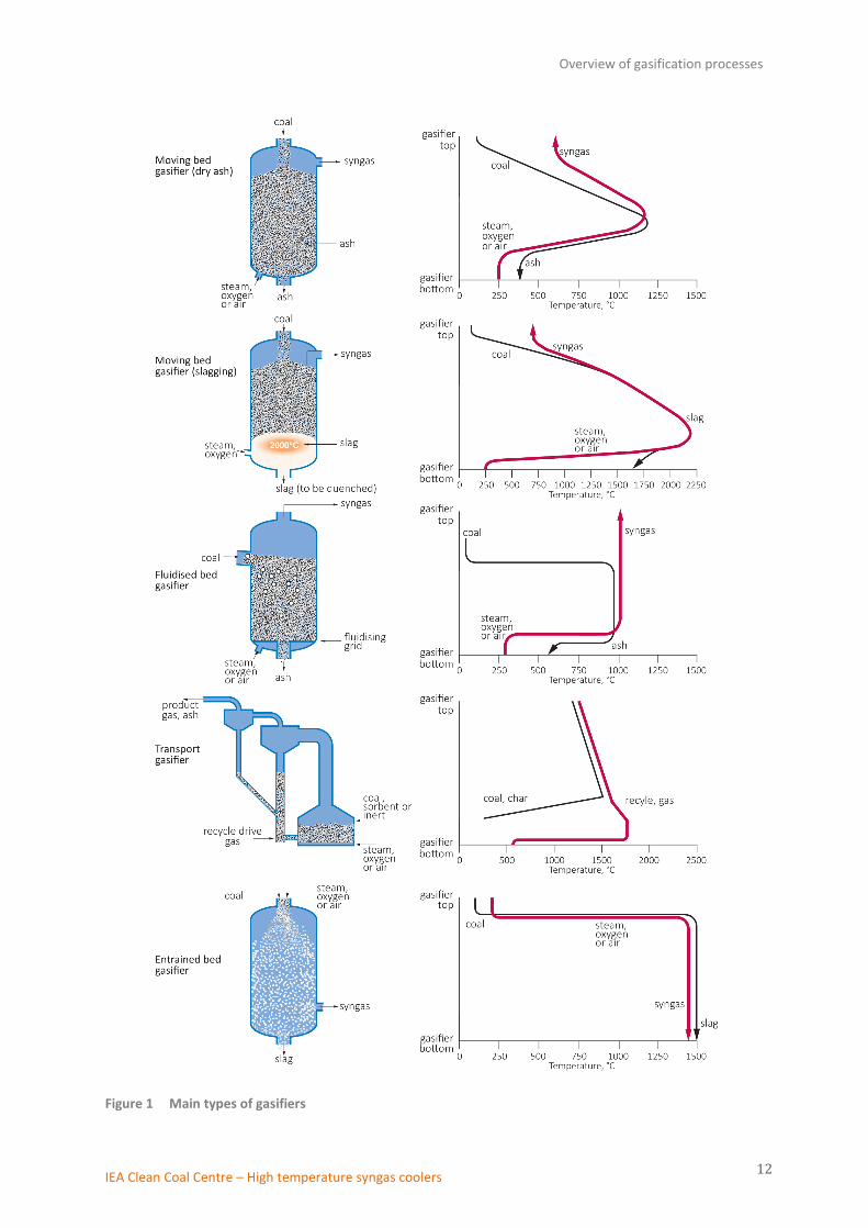
Figure 1 Main types of gasifiers
Overview of gasification processes
IEA Clean Coal Centre – High temperature syngas coolers 13
There is a significant temperature gradient within the bed (see Figure 1). The maximum temperatures in
the combustion zone at the bottom of the reactor are typically in the range of 1500–1800°C for slagging
gasifiers and around 1300°C for dry ash gasifiers. As the flow is counter-current, the gas leaving the
gasifier is cooled by the incoming feed and the gas exit temperature is typically 400–600°C. The moisture
content of the feed coal is the main factor which determines the discharge gas temperature. High
moisture lignite coals result in lower temperatures than low moisture bituminous coals.
As the raw gas traverses through the devolatilisation and drying zone, it contains a significant amount of
tars, phenols, oils and low boiling point hydrocarbons that have been produced in the devolatilisation
zone and are carried upwards by the gas before reaching the gasification zone. The temperatures in the
upper section of the gasifier are not sufficiently high for tars, phenols and other hydrocarbons to
decompose. Methane formation is also very high. As a result, the produced syngas has a high heating
value. The carbon conversion rate in the reactor is very high whilst the consumption of oxygen is low. The
counter-current flow and inherent recuperation of the sensible energy in the gas through devolatilisation
and drying of coal result in a high thermal efficiency of the gasification process and give these gasifiers
higher cold gas efficiency (80–90%) compared to other types of gasifiers. Table 1 compares some of the
characteristics of the different types of gasifiers. Typical examples of moving bed gasifiers include Lurgi
dry ash gasifiers and the British Gas/Lurgi (BGL) slagging gasifiers.
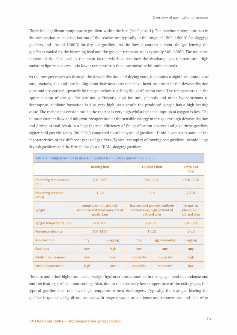
Table 1 Comparison of gasifiers (modified from Cortés and others, 2009)
Moving bed Fluidised bed Entrained flow
Operating temperature (°C)
300–1800 650–1100 1500–1900
Operating pressure (MPa)
1–10 1–4 2.5–8
Syngas contains tar, oil, phenols,
ammonia and small amounts of particulate
low tars and phenols; uniform composition; high content of
ash and char
no tars, or phenols but ash and char
Syngas temperature (°C) 400–600 700–900 900–1600
Residence time (s) 900–3600 5–100 1–10
Ash condition dry slagging dry agglomerating slagging
Coal rank low high low any any
Oxidant requirement low low moderate moderate high
Steam requirement high low moderate moderate low
The tars and other higher molecular weight hydrocarbons contained in the syngas tend to condense and
foul the heating surface upon cooling. Also, due to the relatively low temperature of the exit syngas, this
type of gasifier does not have high temperature heat exchangers. Typically, the raw gas leaving the
gasifier is quenched by direct contact with recycle water to condense and remove tars and oils. After

Overview of gasification processes
IEA Clean Coal Centre – High temperature syngas coolers 14
quench, heat may be recovered from the gas by generation of low pressure steam. Therefore, the cooling
systems adopted in moving bed gasification processes will not be discussed in this report.
2.2 Fluidised bed gasifiers
In a fluidised bed gasifier, a mixture of gasification agent (usually air, but oxygen is also used) and steam
passes through a bed of fuel particles at a high enough velocity to suspend the solids so the resulting bed
within the gasifier acts as a fluid. These gasifiers employ back-mixing, and efficiently mix feed coal
particles with coal particles already undergoing gasification. Coal enters at the side of the reactor into the
hot fluidised bed and mixes rapidly with the bed material and almost instantaneously attains the
gasification temperature. This leads to higher throughputs in fluidised beds, as compared with moving
bed gasifiers. Due to the thorough mixing within the gasifier, a uniform temperature distribution is
obtained in the reactor bed (see Figure 1). Lime, limestone or dolomite can be added for in-bed sulphur
removal. The gasifiers normally operate at moderately high temperatures (900–1100°C) to achieve an
acceptable carbon conversion rate (90–95%) and to decompose most of the tar, oils, phenols, and other
liquid by-products. However, the operating temperatures are usually lower than the ash fusion
temperature so as to avoid clinker formation and the possibility of de-fluidisation of the bed.
Some char particles are entrained in the raw syngas as it leaves the top of the gasifier, but are recovered
and recycled back to the reactor via a cyclone. Ash is removed below the bed and heat is recovered from
the ash by heating the incoming steam and recycle gas. The temperature of syngas exiting a fluidised bed
reactor is usually in the range of 800–1000°C. It is free of tars and with low fly ash content. The cold gas
efficiency is approximately 80%.
Fluidised bed gasifiers may differ in ash conditions (dry or agglomerated) and in design configurations.
Also, depending on the degree of fluidisation and bed height, these types of reactors are sometimes
classified into: bubbling fluidised bed gasifier, circulating fluidised bed gasifier and transport gasifier.
2.2.1 Bubbling fluidised bed gasifier
Gasifying agent is fed under the bed and this ascendant flow with a relatively low velocity creates bubbles
while traversing the bed. Fuel is fed into or above the bed. There is a freeboard above the bubbling bed
where the gas-phase reactions take place. A cyclone at the exit of the gasifier removes the fly ash from the
syngas. The operating temperature of bubbling bed gasifiers is typically in the range of 650–950°C.
2.2.2 Circulating fluidised bed gasifier
The velocity of gasifying agent is higher than that in the bubbling bed gasifiers, to suspend the fuel
particles throughout the reactor. A cyclone separates the particles and recycles them back into the bed.
The operating temperature of circulating bed gasifiers is typically in the range of 800–1000°C.
2.2.3 Transport gasifier
This type of gasifier is between fluidised bed and entrained flow gasifiers. It operates at higher velocities,
riser densities and solids circulation rates than most conventional circulating fluidised bed reactors,

Overview of gasification processes
IEA Clean Coal Centre – High temperature syngas coolers 15
leading to better mixing and higher heat and mass transfer rates. A transport gasifier consists of a mixing
zone, riser, disengager, cyclone, standpipe, loopseal, and J-leg (see Figure 1). The mixing section has a
combustion zone and a coal devolatilisation zone. Coal is fed slightly above the mixing zone in a reducing
atmosphere and is heated rapidly by the circulating solids and combustion gases in a devolatilisation
zone. Limestone is usually added as sulphur sorbent. The combustion zone is fed with recycled char, ash
and sorbent and mixed with the oxidant and steam. The endothermic coal gasification reactions take
place primarily in the riser above the coal feed injection point (gasification zone). Heat for the coal
devolatilisation and gasification reactions is provided by char combustion in the combustion zone. Unlike
conventional fluidised bed gasifiers that have a uniform temperature distribution within the bed, there is
a temperature gradient within transport gasifiers as shown in Figure 1.
Additional residence time in the riser section allows the char gasification, methane/steam reforming,
water gas shift and sulphur capture reactions to occur. The char along with recirculating ash is separated
from the syngas in a cyclone and recycled back to the gasifier via a standpipe and J-leg. The raw gas from
the cyclone is sent to a syngas cooler. The operating temperature of transport gasifiers is between
815-1065°C.
Examples of fluidised bed gasifiers include U-gas gasifier, High Temperature Winkler (HTW) gasifier and
Kellogg, Brown, & Root (KBR) transport integrated gasifier (TRIG).
2.3 Entrained flow gasifiers
Entrained flow gasifiers are characterised by higher velocities and higher temperatures than moving or
fluidised bed gasifiers. They operate at temperatures between 1200°C and 1600°C and pressures range
from 2–8 MPa with most large plants operating at around 2.5 MPa. In an entrained flow gasifier, coal and
oxidant (air or oxygen) and steam are fed concurrently into the gasifier at high velocities and move either
in an up-flow or a down-flow direction. This results in the oxidant and steam surrounding or entraining
the coal particles as they traverse the gasifier in a dense cloud and extremely turbulent flow, which lead
to a uniform temperature distribution within the gasifier vessel ensuring rapid carbon conversion
(see Figure 1). Due to the high velocities, the residence time in these gasifiers is short, typically in the
order of a few seconds. High carbon conversion (98–99.5%) at these conditions is achieved by using
finely ground coal and high gasification temperatures. The syngas leaves the reactor typically at high
temperatures of 1260°C and higher. Given the high operating temperatures, gasifiers of this type melt the
coal ash into vitreous inert slag.
The fine coal feed can be fed into the gasifier in either a dry or slurry form. The slurry feed introduces
water into the reactor that needs to be evaporated. The result of this additional water is a product syngas
with higher H2 to CO ratio, but with a lower gasifier thermal efficiency. The cold gas efficiency is
approximately 80%.
Entrained flow gasifiers are the most versatile type of gasifiers in that they can gasify practically all types
of coal regardless of coal rank, caking characteristics or amount of fines, though feedstocks with lower

Overview of gasification processes
IEA Clean Coal Centre – High temperature syngas coolers 16
ash contents are preferred. Other advantages include high-load capacity, high carbon conversion, and a
product gas rich in CO, CO2, H2, H2O and free of tars and phenols. On the other hand, high gasification
temperatures raise a number of challenges: burner and gasifier reliability due to corrosive and sticky slag,
and the requirement to cool extremely hot syngas. Oxygen consumption in entrained bed gasifiers is
typically the highest among the gasifier types.
Currently, there are several variations of entrained flow gasifiers, such as the GE Energy gasifier, Shell
gasifier and MHI gasifier, available in today’s market. For interested readers, detailed descriptions and
technical reviews of gasification processes and individual commercial gasifiers are available elsewhere
(Breault, 2010; H2-IGCC Project, 2010; Cortés and others, 2009; Fernando, 2008).

High temperature syngas cooling systems
IEA Clean Coal Centre – High temperature syngas coolers 17
3 High temperature syngas cooling systems Syngas leaves a gasifier at high temperatures varying from around 500°C to 1600°C. The raw syngas is
contaminated with various components such as particulate, sulphur and chlorine compounds or tars
which must be removed before the syngas can be used. Gas cleaning processes usually operate at
temperatures considerably lower than that of the gasifier itself, and therefore, there is always the
necessity to cool the syngas. The hot syngas can be cooled by a radiant and/or convective heat exchanger
and/or by a direct quench system. In most cases, it is desirable to recover and make good use of the
sensible heat in the gas, for example, by raising steam for in-plant power generation or process heating.
On the other hand, the characteristics of the various gasification processes and the diversity in the
properties of syngas produced raise considerably different syngas cooling tasks. Consequently, several
syngas cooling systems using various types of coolers with different equipment designs have been
developed.
3.1 Radiant syngas cooler
The sensible heat in high temperature raw syngas (>700-1650°C) can be recovered by a radiant type heat
exchanger (heat recovery boiler). Radiant syngas coolers (RSC) use radiant heat transfer to cool the hot
syngas. The radiant heat exchanger tube arrangement bears some resemblance to cylindrical fired
heaters where cage shaped tube panels are used. Figure 2 illustrates a radiant screen cooler. Hot gas
flows up or down in the radiant cooler, depending upon gasifier design, giving heat to the water that flows
in tubes built into the heat transfer surface. High pressure (HP) steam is generated. The molten slag drops
into a slag quench chamber at the bottom of the radiant syngas cooler where it is cooled and removed for
disposal.
Figure 2 A radiant screen cooler by Alstom (Alstom, 2015)
In general, division walls (or platens) with water tubes built inside are placed inside the RSC. These
division walls increase the heat transfer surface area and therefore enhance radiant heat transfer from
the gas and entrained particles. The division walls, acting as radial platens, are arranged like the spokes of
a wheel, where such radial platens are uniformly spaced at equal intervals. Figure 3 shows the inside of a

High temperature syngas cooling systems
IEA Clean Coal Centre – High temperature syngas coolers 18
RSC with high alloy heat recovery walls. There are variations in RSC designs. The basic structure of a RSC
with double water-cooled cage-walls is illustrated in Figure 4. The RSC is a cylindrical enclosure
constructed with water cooled tubes and membrane, known as the ‘cage-wall’. There are several division
walls inside the inner cage-wall. In all these designs, the platens are confined to an annular region of the
furnace plan area within the RSC. The centre of the furnace is open to allow large slag particles to fall
through the RSC without excessive deposition on the platens.
Figure 3 Inside of a RSC with division walls (Alstom, 2015)
Figure 4 Structure of a RSC (Ni and others, 2009)
As in direct combustion, a radiant heat exchanger is only used for very high temperature operation. It can
be prone to fouling and rappers or blowers can be used for cleaning.

High temperature syngas cooling systems
IEA Clean Coal Centre – High temperature syngas coolers 19
It is necessary to distinguish between radiant syngas coolers and radiant coolers used in gasifier reactors.
Some gasifiers, such as those developed by Shell and Siemens, use a membrane wall inside the reactor
vessel covered with a relatively thin layer of refractory. The membrane wall consists of high-pressure
tubes in which water is circulated and evaporated, generating high-pressure steam. Molten slag in contact
with the cooling surface is cooled and solidified, forming a layer of coating on the surface. The solid slag
layer and refractory provide enough insulation between the cooled membrane wall and reacting gasifier
flows to enable molten slag to contact, wet, and run down the wall and be collected at the bottom of the
gasifier. Therefore, the liquid slag does not come into contact with the wall avoiding corrosion and
erosion problems. It should be noted that the built-in membrane wall is used for the purpose of cooling
and so to extend the life expectancy of the refractory. Heat recovery by steam generation is generally not
a major objective.
3.2 Convective syngas cooler
Convective syngas coolers (CSC) are usually shell and tube type heat exchangers/boilers consisting of a
set of tubes in a container. Convective coolers are generally used to recover heat from coal-derived syngas
with temperatures of 1000°C or lower, depending on the characteristics of coal feed. The heat is
transferred by convection and conduction. High and/or intermediate pressure (IP) steam is generated by
CSC. Both fire tube boiler and water tube boiler designs have been used for CSC. In fire tube boiler designs,
the hot raw syngas flows inside the tubes, while high pressure steam is generated on the outside. This
means that the tubes are subjected to an external pressure because the steam pressure is greater than the
gas pressure in practically all applications. Depending on the design, maximum steam pressure is
between 10 and 15 MPa. An advantage of fire tube boilers is the well-defined gas flow in the tubes.
The maximum material stresses occur at the gas inlet nozzles and therefore the boiler gas inlets need to
be designed carefully in order to cool the gas inlet zone and to ensure the dust-laden syngas does not
cause erosion. Borsig Process Heat Exchanger GmbH (Germany, http://phe.borsig.de/) has developed a
fire tube boiler design for CSC. In this design, a conical inlet section is used to reduce the turbulence at the
inlets. The gas inlet nozzles are designed with reinforcement ribs on the waterside and ceramic coating
on the gas side, as shown in Figure 5. The gas inlet nozzles are cooled by forced and natural circulation.
Boiler water is taken from the lower boiler area and supplied to the double tubes in the gas inlet zone by
recirculating pumps. The application of reinforcement ribs on the waterside allows reduction of the wall
thickness and thereby the wall temperatures in this area. The application of a ceramic protection coating
on the gas side of the inlet nozzles considerably improves the resistance to corrosion and erosion. The
coating also reduces the wall temperatures due to its low conductivity. The tubes are designed as helical
wound heating surfaces. The tube diameter decreases in several steps (usually four to five steps) to
maintain a minimum gas velocity in the range of 25 to 35 m/s. This ensures a self-cleaning effect which is
necessary due to the high particulate burden of the gas. The developer claims that this boiler design is
suitable for all gasification processes. However, it has been used mainly for the GE Process (as discussed
in Section 4.1.1).

High temperature syngas cooling systems
IEA Clean Coal Centre – High temperature syngas coolers 20
Figure 5 Forced cooling of the gas inlet nozzles
Unlike fire tube boilers, water tube boilers pass water through the tubes, which is then heated externally
by hot syngas. The heated water rises into a steam drum, where it can be reheated by a superheater to
achieve even higher steam temperatures. With water tube boilers, the local flow pattern around the tubes
is less even than with a fire tube boiler, and there can be areas of almost stagnant gas and hence the risk
of dust accumulation in the boiler. Water tube boilers can handle higher operating pressures (up to 34
MPa) and provide greater steam output than fire tube boilers. They are commonly used in power
generation plants that require large amounts of high pressure steam production. Because there is less
water volume, a water tube boiler can handle steam fluctuations more precisely than a fire tube boiler
and has generally better turndown. However, the fire tube configuration is often selected for CSC if there
is a high particulate content in the syngas. The high syngas velocity inside tubes can minimise the dust
deposition and hence prevent plugging of the cooler. Water tube boilers are higher in cost than fire tube
boilers. Figure 6 shows the tube arrangement used in a fire tube and a water tube convective heat
exchanger. Various tube arrangements such as double tube, spiral and helically coiled designs have been
developed and applied in convective heat exchangers.

High temperature syngas cooling systems
IEA Clean Coal Centre – High temperature syngas coolers 21
Figure 6 Tube structure inside a fire tube and a water tube convective heat exchanger (Alstom, 2015)
Depending on the type of gasification process the syngas downstream of the steam generator may be
further cooled by a steam superheater (special SCS design) and economisers.
3.3 Direct quenching
Quenching is a rapid cooling process. Quenching can be direct or indirect. Indirect quenching is often used
for the generation of high-pressure steam by specially designed heat exchangers such as radiant coolers
described above. With indirect quenching, there is no direct contact between hot syngas and quenching
medium. With direct quenching, the hot raw syngas is rapidly cooled by injection of cooling medium into
the syngas. Direct quenching can be very efficient and high cooling rates can be achieved. There are
several different direct quenching techniques such as water quench, gas quench and chemical quench.
3.3.1 Water quench
A water quench uses the sensible heat of the syngas to vaporise the injected water. The quench may be a
partial quench or a full (total) quench. In partial quench, only just enough water is evaporated to cool the
syngas to a desired temperature (for instance, 900°C). In full quench, sufficient water is evaporated to
saturate the syngas with water vapour. With a partial quench, heat recovery using convective heat
exchangers could be integrated to produce high-pressure steam, whilst with a full quench, no high-
pressure steam is generated since there is no heat recovery. In both cases, the addition of water drives the
water gas shift reaction to increase the H2/CO ratio.
3.3.2 Gas quench
One example of the use of a gas quench is in the Shell gasifier, where the hot (1500°C) raw syngas exiting
the gasifier is quenched to 900°C by a stream of recycled, cooled, ash-free syngas. The quenched syngas is
High temperature syngas cooling systems
IEA Clean Coal Centre – High temperature syngas coolers 22
then further cooled in a CSC. This way, the heat is used within an unproblematic temperature range.
When a gas quench is used, all the sensible heat in the gas leaving the gasifier is used for raising
additional steam, which results in high efficiencies of IGCC power plants.
3.3.1 Chemical quench
The quench process in which the quenching medium undergoes chemical reactions may be referred to as
chemical quench. There is less experience with chemical quench as this is a concept not widespread in
industry. In principle, the syngas or any other hot process stream may be quenched at the same time as
the thermal energy is used to produce other valuable products. This may give a more effective heat
utilisation than the production of steam. When chemical quench is applied to coal gasification, the
gasification process is divided into two stages. The first stage gasifier operates under slagging conditions
using relatively high oxygen/steam ratios to produce high temperature syngas. The sensible heat in the
hot syngas leaving the first gasification stage is used to gasify a second-stage feed. The coal gasification by
CO2 and H2O in the second stage is an endothermic reaction, and the heat absorbed is sufficient to cool the
syngas to temperatures under which the ash formed in the second stage gasification is dry. With chemical
quench, the sensible heat of the hot syngas is converted into chemical energy of the gas produced (CO and
H2).
Chemical quenching is advantageous because the temperature of the syngas exiting the gasifier is lowered
and thus has less sensible heat, leading to increased cold gas efficiency. Liu and others (2010) compared
the exergy loss of high temperature syngas after quench cooled from 1227°C to 1027°C (1500 to 1300 K)
using different quenching techniques. They found that water quench led to the biggest exergy loss of 7.4%.
The exergy loss after gas quench was 2.3%, one third that of water quench, whilst the exergy loss due to
chemical quench was negligible (0.37%). Chemical quench can be applied in combination with other heat
recovery systems for steam production to achieve increased total process efficiency. A disadvantage is
that some tars may form, making the downstream syngas cleaning more complex.
3.4 Syngas cooling system designs
The selection and design of a syngas cooling and heat recovery system have to consider the
characteristics of the coal feed and syngas produced, the type of gasifier used, and the overall gasification
process application. The temperature of the cooled syngas is determined by the gas cleaning process
immediately downstream of the syngas cooler. Two aspects of gas cleaning need to be carefully
considered in designing the cooling system. These are particulate removal and condensation ― whether
condensation of tars, ammonium chloride or simply water. The first cleaning stage after the syngas cooler
comprises the removal of any solids present in the syngas. Effective solids removal is possible at
temperature below 500°C, whereas for the removal of acid gases and other contaminants (usually using
wet scrubbers) the syngas has to be further cooled to essentially ambient temperatures.

High temperature syngas cooling systems
IEA Clean Coal Centre – High temperature syngas coolers 23
The cost of a syngas cooler is also an important factor influencing the syngas cooling system design as it
can be a significant portion of total capital cost of the gasification plant. Various syngas cooling systems
are in operation in existing IGCC plants.
3.4.1 Radiant and convective cooling
It is common that a syngas cooling system combines different types of syngas coolers. Uebel and others
(2014) identified six design concepts of syngas cooling systems (see Figure 7) that could be adopted by
Siemens entrained flow gasifiers. One or more of these cooling system designs may be integrated into
other types of gasifiers. The radiant and convective syngas cooling design is suitable for cooling hot
syngas with a temperature substantially higher than 900°C. The hot syngas from the gasifier enters a RSC
in which it is cooled to a temperature of approximately 800°C while high-pressure steam is generated.
The syngas from the RSC then flows into a CSC for further cooling to the desired temperature. HP and/or
IP steam is generated in the CSC. This design can achieve maximum heat recovery from syngas, resulting
in the highest potential overall process efficiency. However, the equipment is bulky and expensive.
Figure 7 Syngas cooling system designs (Uebel and others, 2014)
3.4.2 Radiant and quench cooling
This design uses a RSC followed by a full water quench cooler. In this design, the hot syngas is cooled
initially in a RSC. At the bottom of the RSC, both the molten slag and the raw gas are quenched in the
water pool cooler. The cooled slag is removed from the cooler for disposal. The raw gas, saturated with
moisture and free of slag particles, flows out of the quench cooler at a temperature of around 200°C.
Alternatively, depending on the downstream syngas cleaning/treatment process employed, a partial
quench cooler can be used instead of a full water quench cooler. The syngas leaves the partial quench
cooler at a higher temperature that is required by the down stream process. The RSC and water quench
design has lower costs compared to the radiant and convective design but also has a lower heat recovery

High temperature syngas cooling systems
IEA Clean Coal Centre – High temperature syngas coolers 24
rate and therefore, lower efficiency. The RSC and partial quench design has less cooling volume and hence,
a smaller quench cooling vessel compared to full water quench.
3.4.3 Partial quench and convective cooling
In the partial quench and convective cooling design, the hot, raw syngas is first quench cooled (using
water or gas quenching) to a temperature well below the ash melting point of the coal (usually
800-900°C). After the quench, the syngas enters a CSC and is cooled to the desired temperature while
steam is raised. When CO2 capture is desired, water quench has an advantage over gas quench cooling as
the syngas, after water quench cooling, contains a high water content required by the CO shift reaction in
the down stream water-gas shift reactor.
Entrained-flow, two-stage gasifiers have been developed which employ chemical quenching in the
second-stage gasifier. The sensible heat in the syngas leaving the first stage of the gasifier is used in the
endothermic gasification reactions in the second-stage gasification. The syngas exits the gasifier at a
temperature of 1000–1100°C and enters the CSC for cooling and heat recovery.
3.4.4 Total quench cooling
In this design, the hot syngas leaves the gasifier and enters a water spray chamber and a slag quench bath.
Water is sprayed into the quench chamber to cool the hot syngas. The syngas is forced through or
impinges on the water bath surface. The entrained slag is separated from the syngas in the slag quench
bath. The water bath level can be adjusted higher or lower to allow the raw syngas to penetrate into the
water bath at different depths to further reduce the syngas temperature, augment the water-gas shift
reaction, and remove particulates. The raw gas saturated with moisture flows out of the quench cooler at
the required temperature.
3.4.5 Quench versus heat recovery
Sensible heat in the hot raw syngas can represent over 15% of the energy in the feed coal. Recovery of
this heat from syngas is essential for attaining high process efficiency. Heat recovery systems can reclaim
a significant portion of the energy in the feed, depending on the technology employed. However, the
syngas cooler is often one of the most expensive items in a coal gasification complex. As in power
generation and other industrial processes, there is a trade-off between efficiency and capital cost. The
radiant and convective syngas cooling system provides the highest heat recovery rate leading to highest
process efficiency. However, the investment cost is significantly higher than for those cooling systems
described in Sections 3.4.2 to 3.4.4. The efficiency gain of a coal based IGCC plant using Siemens
500 MWth entrained flow gasifier with a heat recovery syngas cooling system (using either a RSC or CSC)
compared to the reference IGCC plant with a total water quench cooling system is shown in Figure 8. It
can be seen from Figure 8 that the maximum efficiency gain can be obtained using a radiant cooler.
However, a RSC is a large, expensive piece of equipment. As illustrated in Figure 9, a RSC is much taller
than the gasifier. The RSC installed in the 250 MWe Polk IGCC plant in Florida (USA), is about 5 metres in
diameter and 30 metres tall, and weighs about 815 tonnes (Higman and van der Burgt, 2008).

High temperature syngas cooling systems
IEA Clean Coal Centre – High temperature syngas coolers 25
Nonetheless, the efficiency improvement over a total quench design justifies this expense under certain
circumstances and a radiant cooler has been adopted in gasification processes by several developers.
Figure 8 Increases in IGCC efficiency and net power output using syngas cooling systems with heat recovery compared to total water quench (Uebel and others, 2014)
Figure 9 A gasifier with a radiant cooler (Alstom, 2015)
While RSC can only work at high temperatures, CSC is capable of effectively recovering sensible heat in
syngas with relatively low temperatures ranged from 300°C to 900°C. A CSC also has a smaller footprint
than a RSC. Syngas cooling and heat recovery systems using convective coolers are employed in various
gasification processes developed by several companies/developers. However, convective coolers are
High temperature syngas cooling systems
IEA Clean Coal Centre – High temperature syngas coolers 26
more sensitive to slag deposition and condensation compared to RSC and quench coolers. They have
higher risk of fouling and plugging which can cause a plant trip and high pressure losses leading to
increased downtime and higher maintenance costs (Uebel and others, 2014).
There is no heat recovery in the total quench design and the sensible heat of the high temperature syngas
is converted to low level process heat rather than high-pressure steam. In spite of the negative impact on
efficiency, a total quench cooling system has much lower capital cost and can be justified when low cost
feedstock is available. Total quench design is beneficial for the downstream water-gas shift reaction (H2O
+ CO → H2 + CO2), which increases the H2/CO ratio. The saturated syngas exiting a quench cooler has near
the optimum H2O/CO ratio for feed into a water-gas shift reactor. It is used in chemical applications,
particularly where a CO shift reaction for hydrogen production is involved. Should CO2 capture have to be
implemented from the beginning of a project (as opposed to being retrofitted later), then this cooling
technique would probably be favoured for coal based IGCC applications. Non-quench designs that require
CO2 capture will have to add steam to the syngas before it is sent to a water-gas shift reactor to convert
the CO in the syngas to CO2. Lorenzo and colleagues (2008) analysed the co-production of hydrogen and
electricity from coal using the GE entrained flow gasification process and with carbon capture. Their
results showed that, compared with total quench cooling, the radiant and convective cooling offered only
a modest increase in plant efficiency. They concluded that this efficiency improvement could not justify
the cost as the cost of H2 production would be 10% higher if radiant and convective cooling was used
instead of total quench cooling. Results from a more recent investigation into an IGCC power plant with
carbon capture showed that when the gas quench and convective cooling system in the standard Shell
coal gasifier design is replaced with a water quench cooler, the overall efficiency will be decreased by
1.4 percentage points. However, the Shell IGCC plant with CO2 capture using a water quench syngas
cooling design has significantly lower capital, operating and maintenance costs, leading to a levelised cost
of electricity 8.5% lower compared to that of the standard design (Kreutz and others, 2010).
In a total quench cooling system, large quantities of water are used and thus contaminated by the raw
syngas, requiring complex waste water treatment. Therefore, the total quench design has additional
operating problems such as those caused by corrosion of gasifier walls, increased water treating facilities,
increased discharge water permitting issues, and added operating and maintenance costs when
compared to radiant and convective cooling designs.
3.5 Comments
Although raw syngas leaving the gasifier is at high temperature, conventional methods for syngas
cleaning are typically carried out by scrubbing using chemical or physical absorption processes that
operate at low temperatures. After contaminant removal, the syngas has to be reheated prior to its use in
a gas turbine or other chemical synthesis process. These process swings adversely impact the plant’s
energy efficiency and cost. Techno-economic analysis shows that syngas cleaning processes amenable to
higher operating temperatures could significantly reduce this efficiency loss and improve the commercial
viability of gasification plants. Extensive R&D activities have been carried out in the past three decades to

High temperature syngas cooling systems
IEA Clean Coal Centre – High temperature syngas coolers 27
develop high-temperature gas cleaning processes. The focus of most high temperature syngas cleanup has
been on the removal of particulates and gaseous contaminants such as sulphur, chloride and alkalis. High
temperature particulate cleanup has been one of the most important improvements to commercial syngas
applications. Ceramic candle filters emerged as the most promising technology for particulate removal at
temperatures up to 1000°C and is subject to intensive investigations. However, there are some
fundamental limitations and practical problems with the high temperature application of ceramic candle
filters. So far, the operating temperature of ceramic filters is limited to about 400°C or lower. They also
suffer low availabilities and reliabilities, and are often one of the major causes of plant downtimes.
It is also critical that, while improving efficiency and reducing cost, the gas cleaning removes a wide
variety of coal contaminants such as hydrogen sulphide, ammonia, hydrogen chloride, and carbonyl
sulphide, as well as various forms of trace metals to extremely low levels. Accordingly, there has been
R&D in this area focusing on the development of high-efficiency processes that operate at moderate to
high temperatures and provide multi-contaminant control to protect the downstream units such as gas
turbines and catalytic reactors, or to meet stringent environmental standards. These works are currently
ongoing.
Commercial syngas cooling systems
IEA Clean Coal Centre – High temperature syngas coolers 28
4 Commercial syngas cooling systems
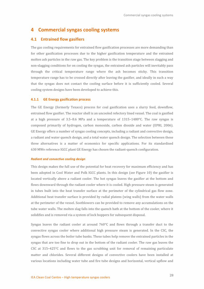
4.1 Entrained flow gasifiers
The gas cooling requirements for entrained flow gasification processes are more demanding than
for other gasification processes due to the higher gasification temperature and the entrained
molten ash particles in the raw gas. The key problem is the transition stage between slagging and
non-slagging conditions for on cooling the syngas, the entrained ash particles will inevitably pass
through the critical temperature range where the ash becomes sticky. This transition
temperature range has to be crossed directly after leaving the gasifier, and ideally in such a way
that the syngas does not contact the cooling surface before it is sufficiently cooled. Several
cooling system designs have been developed to achieve this.
4.1.1 GE Energy gasification process
The GE Energy (formerly Texaco) process for coal gasification uses a slurry feed, downflow,
entrained flow gasifier. The reactor shell is an uncooled refectory lined vessel. The coal is gasified
at a high pressure of 3.5–8.6 MPa and a temperature of 1315–1480°C. The raw syngas is
composed primarily of hydrogen, carbon monoxide, carbon dioxide and water (EPRI, 2006).
GE Energy offers a number of syngas cooling concepts, including a radiant and convective design,
a radiant and water quench design, and a total water quench design. The selection between these
three alternatives is a matter of economics for specific applications. For its standardised
630 MWe reference IGCC plant GE Energy has chosen the radiant-quench configuration.
Radiant and convective cooling design
This design makes the full use of the potential for heat recovery for maximum efficiency and has
been adopted in Cool Water and Polk IGCC plants. In this design (see Figure 10) the gasifier is
located vertically above a radiant cooler. The hot syngas leaves the gasifier at the bottom and
flows downward through the radiant cooler where it is cooled. High pressure steam is generated
in tubes built into the heat transfer surface at the perimeter of the cylindrical gas flow zone.
Additional heat transfer surface is provided by radial platens (wing walls) from the water walls
at the perimeter of the vessel. Sootblowers can be provided to remove any accumulations on the
tube water walls. The molten slag falls into the quench bath at the bottom of the cooler, where it
solidifies and is removed via a system of lock hoppers for subsequent disposal.
Syngas leaves the radiant cooler at around 760°C and flows through a transfer duct to the
convective syngas cooler where additional high pressure steam is generated. In the CSC, the
syngas flows across the boiler tube banks. These tubes help remove the entrained particles in the
syngas that are too fine to drop out in the bottom of the radiant cooler. The raw gas leaves the
CSC at 315–425°C and flows to the gas scrubbing unit for removal of remaining particulate
matter and chlorides. Several different designs of convective coolers have been installed at
various locations including water tube and fire tube designs and horizontal, vertical upflow and

Commercial syngas cooling systems
IEA Clean Coal Centre – High temperature syngas coolers 29
downflow configurations. The Cool Water project had an upflow duct followed by downflow over
boiler tube banks, whilst at Polk IGCC plant, the syngas flow from the bottom of the radiant
cooler is split into two parallel horizontal fire tube convective exchangers (EPRI, 2006; Higman
and van der Burgt, 2008).
Figure 10 Syngas cooling options for GE process (Koppel and Lorden, 2009)
Radiant and water quench design
In this design, the hot raw syngas leaving the gasifier flows downwards into the same radiant
cooler described above and is cooled by generating high pressure steam. However, at the bottom
of the radiant cooler both the raw gas and the slag are quenched in water and cooled. Slag and
any unconverted char are removed from the bottom of the quench chamber via a lock hopper
system as previously described. The raw gas saturated with moisture then flows to the gas
scrubbing unit at a temperature of 200–220°C for further removal of particulate matter and
chlorides (EPRI, 2006; Rubin and others, 2007). This design concept has been applied to the
syngas cooling system at Duke Energy’s coal-fuelled 613 (net) MWe Edwardsport IGCC plant in
Indiana (USA), which began commercial operation using natural gas in 2013.
Total quench design
In this design, the gasifier is directly connected to the quench chamber, making a compact
configuration (see Figure 10). The hot syngas and the molten slag particles flow downward
through a water spray chamber and a slag quench bath. Water is sprayed just beneath the partial
oxidation chamber to cool the hot syngas. The entrained slag is separated from the syngas in the
slag quench bath. There is no high pressure steam generation in this method as in the previous
two designs. The raw gas saturated with moisture flows to the gas scrubbing unit at a
temperature of 205–260°C depending on the pressure (EPRI, 2006; Rubin and others, 2007).

Commercial syngas cooling systems
IEA Clean Coal Centre – High temperature syngas coolers 30
4.1.2 The Shell coal gasifier
The Shell Coal Gasification Process (SCGP) uses a dry-feed, pressurised, oxygen-blown, up-flow,
entrained-flow gasifier. Figure 11 shows a simplified SCGP flow sheet. The gasifier features a
refractory-lined reactor vessel, equipped with an inner membrane wall consisting of circulating
water/steam-filled tubes. Inner reactor wall temperature is controlled by circulating water
through the membrane wall, producing steam. Dried, pulverised coal is fed via two feed injectors
to the opposite sides of the gasifier, near the bottom, through pressurised lock hoppers using a
transport gas (syngas or nitrogen). Preheated oxygen and steam are mixed and fed to the gasifier
via the same injectors or below the coal injection points. Shell coal gasifiers typically operate at a
pressure range of 2–4 MPa. The temperature of the gasifier is kept within the range of 1400–
1700°C by adjusting the flow rates of coal, oxygen and steam. Most of the ash forms slag inside
the gasifier at these high temperatures and then flows down and exits from the bottom of the
gasifier. The syngas produced consists primarily of carbon monoxide and hydrogen (typically
around 60% CO and 30% H2). The hot syngas flows upward out of the gasification zone with part
of the molten ash entrained. The syngas cooling system is an integral part of Shell gasifier
technology.
Figure 11 Simplified Shell coal gasification process (de Graaf, 2008)
Gas quench and CSC design
At the top of the gasifier the raw syngas enters the quench zone where it is quench cooled from
1500–1600°C to about 900°C with cold, dust-free recycled syngas of about 250°C, to ensure that
the entrained molten fly slag is solidified prior to entering the CSC. The quench is designed in
such a way that the hot gases and the slag do not come into contact with the wall before they are
cooled to a temperature where the slag becomes non-sticky. The gas quench section is connected
through a steam-cooled duct to the CSC. The CSC is a water tube boiler in which the syngas flows
from the top downward (see Figure 12). The CSC consists of economisers, medium- and high-
pressure evaporators, and some superheaters. The vessel wall is protected from direct contact

Commercial syngas cooling systems
IEA Clean Coal Centre – High temperature syngas coolers 31
with the hot gas by wall heating surfaces. The main heating surfaces consist of concentric
cylinders of helical coiled tubes installed within the wall panels. To facilitate mechanical cleaning
(with rappers) of the cylinders, the tubes are welded together to form a membrane. The steam
conditions in the syngas cooler are 12 MPa and 400°C. In principle, the steam conditions could
reach 13.9 MPa and 540°C. However, it is usually determined that, for an IGCC plant, the
superheating of the high-pressure steam can be more economically accomplished in the Heat
Recovery Steam Generator (HRSG) at the gas turbine exhaust rather than in the more
aggressively corrosive atmosphere at the top of the syngas cooler. The saturated steam
conditions in the syngas cooler can be as high as 12.5 MPa and 400°C, in which case a metal with
a high chromium content would have to be chosen for the high pressure cooling surfaces.
Depending upon coal prices, it may be more economic to raise steam at a lower pressure of
5 MPa when a lower cost ferritic material can be selected for the medium pressure surfaces
(EPRI, 2006; NETL, http://www.netl.doe.gov/).
Figure 12 Syngas cooling options for SCGP (van Paasen and others, 2012)
The syngas leaves the CSC at a temperature of around 250–300°C and enters the fly ash removal
system, where the majority of the fly ash contained in the gas is removed. After fly ash removal, a
portion (about 50%) of the solids free gas (<5 mg/m3) is compressed and recycled as quench gas
to the top of the gasifier. The balance of the gas is sent to a wet scrubber to remove any
remaining fly ash and is then sent to the acid gas removal system.
The Shell SCGP with gas quench and CSC cooling system was commercially demonstrated at
Nuon Power’s decommissioned Buggenum IGCC plant in the Netherlands. The plant was capable
of gasifying 2000 tonnes of coal per day to produce 253 MWe of net electricity.
Top flow water quench cooling design
Recently, Shell has introduced a partial water quench cooling system to replace the CSC. With this
design, the gasification process remains the same as that described above except that the CSC is
Commercial syngas cooling systems
IEA Clean Coal Centre – High temperature syngas coolers 32
replaced by a water quench cooler, and the dry solids removal is replaced with a wet fly ash
removal unit. The hot, raw syngas leaving the gasification zone is initially quench cooled by
recycled, cold syngas before entering the water quench cooler. The syngas then flows from the
top downward to the water quench cooler, which is a wide empty vessel that is located below the
gas reversal chamber (see Figure 12). Water at about 230°C is sprayed into the vessel, near the
top, via proprietary designed nozzles to produce a fine mist for optimum water evaporation and
syngas cooling. The cooled syngas exits the water quench cooler at a temperature of
approximately 425°C.
The SCGP with partial water quench has a simpler system design and smaller footprint, and
therefore lower capital cost compared to that of SCGP with gas quench and CSC cooling system. It
improves the fuel flexibility by enabling gasification of coals that cannot be processed with a CSC
due to fouling. It is also advantageous when CO shift is planned immediately downstream of the
gasifier due to its better integration with a downstream shift reactor (Fournier G, 2009; de Graaf,
2008).
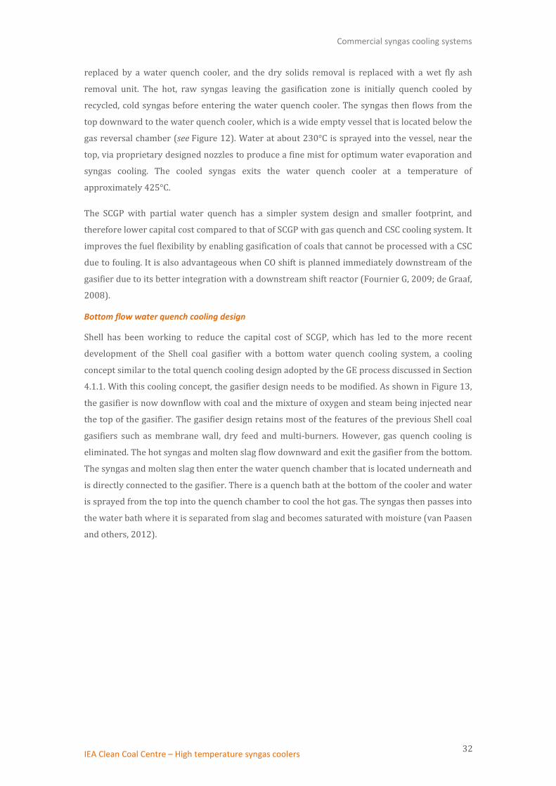
Bottom flow water quench cooling design
Shell has been working to reduce the capital cost of SCGP, which has led to the more recent
development of the Shell coal gasifier with a bottom water quench cooling system, a cooling
concept similar to the total quench cooling design adopted by the GE process discussed in Section
4.1.1. With this cooling concept, the gasifier design needs to be modified. As shown in Figure 13,
the gasifier is now downflow with coal and the mixture of oxygen and steam being injected near
the top of the gasifier. The gasifier design retains most of the features of the previous Shell coal
gasifiers such as membrane wall, dry feed and multi-burners. However, gas quench cooling is
eliminated. The hot syngas and molten slag flow downward and exit the gasifier from the bottom.
The syngas and molten slag then enter the water quench chamber that is located underneath and
is directly connected to the gasifier. There is a quench bath at the bottom of the cooler and water
is sprayed from the top into the quench chamber to cool the hot gas. The syngas then passes into
the water bath where it is separated from slag and becomes saturated with moisture (van Paasen
and others, 2012).

Commercial syngas cooling systems
IEA Clean Coal Centre – High temperature syngas coolers 33
Figure 13 Bottom-quench SCGP gasifier and water quench cooler design (van Paasen and others, 2012)
The SCGP with bottom quench has the simplest process configuration and much smaller footprint
compared to the SCGP with the other two cooling system designs (see Figure 12). This means less
steel, less equipment, and a shorter manufacturing time, which substantially reduces capital
costs (by up to 30%). It is more fuel flexible but has a lower energy efficiency. In 2013, Shell and
Chinese Wison Engineering successfully started a 1000 t/d SCGP bottom-quench technology
demonstration plant in the Nanjing Industrial Park, which had 99% carbon conversion. In
January 2014, a Chinese company Hulunbeier Jinxin, a subsidiary of the Yuntianhua Group,
signed a licensing agreement for a bottom-quench gasifier to process lignite feedstock (van den
Berg and others, 2014).
4.1.3 The PRENFLO gasifier
Developed by Krupp Koppers and currently offered by Uhde (Krupp Koppers merged with Uhde
in 1997), the PRENFLO technology shares many common features with Shell SCGP. Both employ
dry feed using similar pneumatic conveying feed systems and opposed fuel injectors, multiple
burners and a membrane wall. The PRENFLO gasifier operates at elevated pressure (≥4 MPa)
and gasification temperatures of >2000°C. The syngas temperature at the gasifier outlet is in the
range of 1350–1600°C. The PRENFLO gasifier is offered with two cooling options, the PRENFLO
with steam generation (PSG) and PRENFLO direct quench (PDQ).
PRENFLO PSG cooling system is integrated with and is located on top of the gasifier. It consists of
an upflow/downflow (two pass) gas quench pipe and water tube CSC as illustrated in Figure 14.
Pulverised coal and oxygen or oxygen/steam mix are injected near the bottom of the gasifier and
flow upward through the gasifier. The hot raw syngas exits from the top of the gasifier and enters
the quench chamber where it is cooled to around 800°C by mixing directly with a quench gas at

Commercial syngas cooling systems
IEA Clean Coal Centre – High temperature syngas coolers 34
235°C. The cooled syngas flows up, leaves the quench chamber from the top and then flows down
through the CSC. The syngas is further cooled in the CSC while producing high-pressure steam.
The syngas exits from the bottom of the CSC at a temperature lower than 470°C and enters a
second, external CSC where it is cooled to a temperature around 235°C. Medium-pressure steam
is generated in the second CSC (Coca, nd).
Figure 14 PRENFLO PSG cooling system (Coca, nd)
PRENFLO PSG technology is used at the 300 MWe Puertollano IGCC power plant, Spain. This
plant operates with a mixture (50:50) of petroleum coke and coal.
Similar to the Shell’s bottom-quench SCGP, PRENFLO PDQ uses a full water quench cooler that is
located underneath and is directly connected to the gasifier. Pulverised coal and oxygen or
oxygen/steam mixture are injected near the top of the gasifier. The hot syngas and molten slag
flow downward, exit the gasifier from the bottom and then enter the water quench chamber.
There is a quench bath at the bottom of the cooler and water is sprayed from the top into the
quench chamber to cool the hot gas. The syngas then passes into the water bath where it is
separated from slag and become saturated with moisture. The cooled syngas leaves the quench
cooler at a temperature of 200–250°C (Thyssenkrupp, 2015).
4.1.4 The E-Gas gasifier
Currently owned by CB&I, the E-Gas gasifier is a slurry fed, oxygen blown, pressurised, upflow,
entrained flow slagging gasifier. The E-Gas gasifier consists of two stages, a slagging first stage
and a non-slagging second stage as shown in Figure 15. The unique two-stage operation
facilitates chemical quench cooling of the syngas in the second stage.

Commercial syngas cooling systems
IEA Clean Coal Centre – High temperature syngas coolers 35
Figure 15 E-Gas gasification process
In the current standard IGCC design, about 70–75% of the total slurry feed is fed along with
oxygen to the first (or bottom) stage of the gasifier through two opposing mixing nozzles, one on
each end of the horizontal section of the gasifier. The first stage is a horizontal, refractory-lined
vessel with two horizontally opposed burners. This stage involves highly exothermic oxidation
reactions and operates at 1400°C and 2.8 MPa typically. The gasification/oxidation reactions take
place rapidly and the coal is almost totally gasified in this environment to produce the raw
syngas consisting principally of H2, CO, CO2 and H2O. Ash in the coal melts and flows out of the
bottom of the gasifier vessel as slag. The hot raw syngas generated in the first stage flows up
from the horizontal section into the second (top) stage of the gasifier. The second stage is a
vertical refractory lined vessel in which the remaining slurry is added which reacts with the hot
syngas stream exiting the first stage. The coal undergoes devolatilisation, pyrolysis and partial
gasification thereby generating additional syngas with a higher heating value since no additional
oxygen is introduced into the second stage. The endothermic gasification/devolatilisation
reactions in this stage reduce the final gas temperature to about 1000–1050°C. Unreacted coal
(char) is carried over with the syngas.
The hot raw syngas with entrained particulate matter exiting the gasifier is cooled from 1040°C
to 370°C in a convective syngas cooler. The syngas cooler is a vertical fire-tube heat recovery
boiler. This unit generates saturated high-pressure steam, up to 13 MPa. Steam from the high-
temperature heat recovery system is superheated in the gas turbine heat recovery system for use
in power generation. Alternatively, syngas can be superheated to more modest temperatures of
400-420°C in the syngas cooler (EPRI, 2006; Wabash River Energy/US DOE, 2000).
The E-Gas coal gasification technology is incorporated in the Wabash River Coal Gasification
Repowering Project, funded under the DOE Clean Coal Demonstration Program in the 1990s. The
Wabash IGCC plant, which runs on bituminous coal, has been in operation since 1995.
Commercial syngas cooling systems
IEA Clean Coal Centre – High temperature syngas coolers 36
4.1.5 Other entrained flow gasifier cooling systems
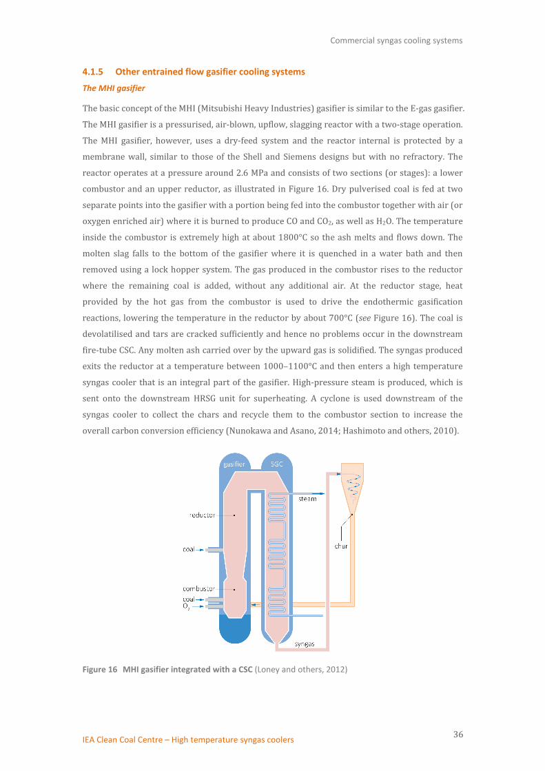
The MHI gasifier
The basic concept of the MHI (Mitsubishi Heavy Industries) gasifier is similar to the E-gas gasifier.
The MHI gasifier is a pressurised, air-blown, upflow, slagging reactor with a two-stage operation.
The MHI gasifier, however, uses a dry-feed system and the reactor internal is protected by a
membrane wall, similar to those of the Shell and Siemens designs but with no refractory. The
reactor operates at a pressure around 2.6 MPa and consists of two sections (or stages): a lower
combustor and an upper reductor, as illustrated in Figure 16. Dry pulverised coal is fed at two
separate points into the gasifier with a portion being fed into the combustor together with air (or
oxygen enriched air) where it is burned to produce CO and CO2, as well as H2O. The temperature
inside the combustor is extremely high at about 1800°C so the ash melts and flows down. The
molten slag falls to the bottom of the gasifier where it is quenched in a water bath and then
removed using a lock hopper system. The gas produced in the combustor rises to the reductor
where the remaining coal is added, without any additional air. At the reductor stage, heat
provided by the hot gas from the combustor is used to drive the endothermic gasification
reactions, lowering the temperature in the reductor by about 700°C (see Figure 16). The coal is
devolatilised and tars are cracked sufficiently and hence no problems occur in the downstream
fire-tube CSC. Any molten ash carried over by the upward gas is solidified. The syngas produced
exits the reductor at a temperature between 1000–1100°C and then enters a high temperature
syngas cooler that is an integral part of the gasifier. High-pressure steam is produced, which is
sent onto the downstream HRSG unit for superheating. A cyclone is used downstream of the
syngas cooler to collect the chars and recycle them to the combustor section to increase the
overall carbon conversion efficiency (Nunokawa and Asano, 2014; Hashimoto and others, 2010).
Figure 16 MHI gasifier integrated with a CSC (Loney and others, 2012)

Commercial syngas cooling systems
IEA Clean Coal Centre – High temperature syngas coolers 37
The MHI gasification technology has been demonstrated in the Nakoso (Japan) 250 MWe IGCC
plant. The demonstration completed in 2013 and the Nasako IGCC plant has since been in
commercial operation.
The current focus of the effort is on air-blown (or enriched air blown) IGCC application. R&D
activities are being carried out to develop an oxygen-blown system for coal to fuels and
chemicals applications.
The EAGLE gasifier
The Electric Power Development Corporation (Japan) has been working on developing the
EAGLE gasifier, which is a pressurised, single-chamber two-stage spiral-flow gasifier with
water-cooled membrane wall. Similar to the E-Gas gasifier and MHI gasifier, the EAGLE gasifier is
a two-stage reactor but it operates with a dry feed and in an oxygen-blown mode. Another
unique feature of the EAGLE gasifier is its tangential feed injection and burner system, as shown
in Figure 17a, which allows a spiral flow pattern to be developed along the inter-reactor wall
between the upper and the lower reactor stage, resulting in a higher overall gasification
efficiency due to the longer residence time and more efficient slag removal.
Figure 17b shows an EAGLE gasifier vessel with a radiant cooler on top of the gasifier reactor.
The gasifier operates at 2.5 MPa and has four coal burners at each stage as well as two char
burners in the lower (first) stage. About equal quantities of pulverised coal is injected into both
lower and upper (second) stage of the gasifier. The gasification reaction is controlled by
adjusting the oxygen flow rate into the two stages. The first stage operates in an oxygen rich
mode at a temperature of around 1600°C. The combustion gas produced in the lower stage rises
into the upper stage where the hot gas drives the endothermic gasification reactions to produce
syngas. The upper stage operates in oxygen lean and non-slagging mode. The particulate matter
in the syngas contains unreacted char and ash. They are removed from the raw syngas
downstream of the syngas cooler and recycled back to the first stage.
The hot syngas leaving the gasifier reactor at a temperature of around 1150°C is quenched with
recycled, cooled syngas. Up to 10% (by volume) of recycled syngas from the outlet of the primary
water scrubber is introduced at the throat section of the gasifier into the stream of the hot raw
syngas to prevent slagging and fouling in the downstream syngas cooler. The quenched syngas
flows up through the heat exchanger in the upper part of the gasifier where the heat in the
syngas is recovered by producing high-temperature, high-pressure steam. The syngas leaving the
gasifier vessel then enters a CSC where it is further cooled to a temperature of around 350-400°C
(Tajima and Tsunoda, 2002; Nagasaki and others, 2013).

Commercial syngas cooling systems
IEA Clean Coal Centre – High temperature syngas coolers 38
Figure 17 Simplified drawings of the EAGLE gasifier
The EAGLE technology is currently being demonstrated in a 150-t/d pilot plant facility at J-Power
Wakamatsu Research Institute in Kitakyushu City, Japan.
Siemens Fuel Gasifier (SFG)
Formerly Future Energy/GSP/Noell, the SFG is a dry-feed, pressurised reactor, which can be
supplied with either a refractory lining for low ash (<2% by weight) feedstocks or with a cooling
screen in the gasification section of the gasifier. The reactor with cooling screen and pneumatic
dense flow feeding system is the preferred design for coal, resulting in high carbon conversion
efficiencies (>98%). The cooling screen consists of a gas-tight membrane wall covered with a SiC
castable onto which a layer of molten slag is deposited. Coal together with oxygen and steam is
supplied via top-mounted burners and flows downwards in the reaction chamber. Gasification
takes place at temperatures of around 1300°C to 1800°C and a pressure of ≥4 MPa. Depending on
the application, the gasifier can use either total or partial quench cooling. The cooling concepts
are similar to the radiant and water quench design and the total quench design adopted by GE.
With the total quench cooling design, raw gas and slag exiting the gasifier enter a quench
chamber that is arranged beneath the reaction chamber. By injection of water the gas is cooled to
temperatures of around 220°C and the molten slag solidifies (Siemens, 2012).
For IGCC plants with carbon capture and storage (CCS), a syngas cooler design with heat
recovery and partial water quench cooling has advantages in conjunction with the CO-shift for
pre-combustion CO2 removal. Siemens has been investigating cooling concepts that integrate
heat recovery and cooling of high temperature syngas and has recently concluded that concept A
illustrated in Figure 7 is advantageous for an optimised and economic gasification process. With
this cooling concept, the gasification vessel consists of a gasifier, a radiant cooler and a water
quench vessel. The raw, hot syngas exits from the bottom of the gasifier and flows down through
the radiant cooler where it is cooled from around 1650°C to about 800°C. The syngas then enters

Commercial syngas cooling systems
IEA Clean Coal Centre – High temperature syngas coolers 39
the water quench chamber and is cooled to a temperature of around 220°C (Guenther, 2012;
Uebel and others, 2014).
4.2 Fluidised bed gasifiers
4.2.1 KBR Transport Integrated Gasifier (TRIG)
As described in Section 2.2.3 the TRIG is a circulating fluidised bed reactor that operates in either
air- or oxygen-blown mode. As illustrated in Figure 18, the gasifier consists of an assembly of
refractory-lined pipe that includes a mixing zone, riser, solids separation and collection unit, and
solids recycle section. Steam and air/oxygen are mixed together and introduced in the lower
mixing zone while fuel, sorbent (for sulphur capture) and additional air or oxygen and steam are
added in the upper mixing zone. The steam and air/oxygen, fuel, sorbent, and solids from the
standpipe are mixed together in the upper mixing zone. The gas and solids move up the riser
before entering the disengager which separates larger particles by gravity. Most of the solids flow
from the disengager into the standpipe, while the remaining solids flow to the cyclone and are
removed. The gas exiting the gasifier enters a high temperature syngas cooler to lower the gas
temperature before it enters a particulate filter system to remove the remaining fine particulate
matter.
TRIG has an operating temperature of approximately 954°C (1750°F) for Powder River Basin
(PRB) subbituminous coal and lignite and operating pressure up to 2 MPa. For a coal-to-SNG
(substitute natural gas) process, the raw, hot syngas containing a small amount of fine particulate
exits the TRIG at 900-925°C (1650-1700°F) and is cooled to about 370°C (700°F) in a CSC. As
shown in Figure 19 the CSC consists of three heat exchange stages: steam generator, superheater
and economiser. The first stage of the syngas cooler is the steam generator. Here, HP steam is
produced while the syngas is cooled to approximately 730°C (1350°F). The middle section of the
syngas cooler is the superheater, where HP steam from the steam drum within the syngas cooler
along with 8.6 MPa saturated HP steam from the downstream methanation process is
superheated to 510°C (950°F). The final section of the syngas cooler is the economiser, where the
syngas is cooled to about 370°C (700°F). Boiler feed water enters the economiser at 195°C
(385°F) and 8.6 MPa. Water is then heated to about 300°C (574°F) and flows to the HP steam
drum (Ariyapadi and others, 2009).
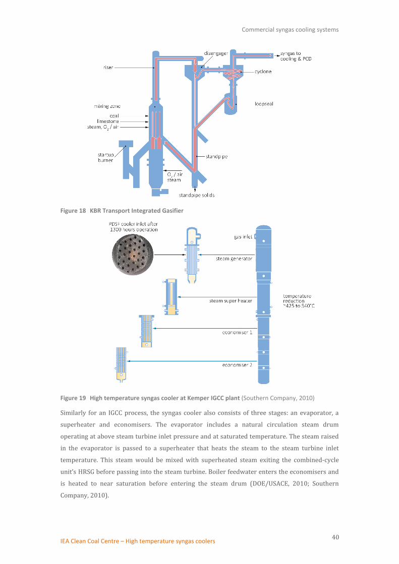
Commercial syngas cooling systems
IEA Clean Coal Centre – High temperature syngas coolers 40
Figure 18 KBR Transport Integrated Gasifier
Figure 19 High temperature syngas cooler at Kemper IGCC plant (Southern Company, 2010)
Similarly for an IGCC process, the syngas cooler also consists of three stages: an evaporator, a
superheater and economisers. The evaporator includes a natural circulation steam drum
operating at above steam turbine inlet pressure and at saturated temperature. The steam raised
in the evaporator is passed to a superheater that heats the steam to the steam turbine inlet
temperature. This steam would be mixed with superheated steam exiting the combined-cycle
unit’s HRSG before passing into the steam turbine. Boiler feedwater enters the economisers and
is heated to near saturation before entering the steam drum (DOE/USACE, 2010; Southern
Company, 2010).

Commercial syngas cooling systems
IEA Clean Coal Centre – High temperature syngas coolers 41
The TRIG technology has been selected for the Kemper County Project (also called the Kemper
County Energy Facility), which is a lignite fuelled IGCC power generating plant and will be owned
and operated by Mississippi Power, a subsidiary of Southern Company (USA). The plant design
incorporates two air-blown TRIG gasifiers with a net capacity of 582 MWe, and carbon capture
technologies to capture at least 65% of CO2. The construction started in 2010 and the plant is
expected to start commercial operation in 2016 (http://www.mississippipower.com/).
4.2.2 High Temperature Winkler (HTW) Gasifier
Developed by Rheinbraun AG (now RWE) and acquired by ThyssenKrupp Uhde in 2011, the HTW
gasifier is a circulating fluidised bed reactor which operates in either air- or oxygen-blown mode.
It is a dry-feed, pressurised, dry ash gasifier and can operate at 800–1000°C and 1–3 MPa. The
temperature is controlled to ensure that it does not exceed the ash softening point. A key
advantage of the technology is the capability to gasify a variety of different feedstocks, including
all grades of more reactive low-rank coals with a higher ash softening temperature such as lignite,
and also various forms of biomass. Due to the relatively high gasification temperature, the syngas
does not contain any higher molecular weight hydrocarbons such as tars, phenols, and other
heavy aromatics. The raw syngas exiting the gasifier is cooled in a CSC from approximately 900°C
to around 300°C. An HTW demonstration plant (25 t/h dry lignite or 140 MWth) was built at
Berrenrath (Germany) which was operated for over 10 years from 1986 to 1997. The design of
the water tube cooler employed at the HTW demonstration plant is shown in Figure 20. The raw
syngas with a temperature of approximately 900°C and a particulate content of around 30g/m3
was cooled in the syngas cooler. Saturated steam of 360°C and 1.8 MPa was generated, which was
further heated to become superheated steam with a temperature of 580°C and a pressure of
3.5 MPa (Bassett, 2012; Renzenbrink W and others, nd).
A horizontal fire tube cooler was also tested at the demonstration plant. Test results showed that
both the water tube cooler and fire tube cooler could be employed to meet the cooling
requirement. With optimised design and operating conditions, dust deposition and/or caking,
fouling as well as erosion and corrosion can be minimised. The developer recommends that the
water tube cooler be utilised for IGCC applications where supercritical steam conditions are used
to optimise the overall process efficiency, whilst for applications that require medium-pressure
steam (<15 MPa), the fire tube cooler should be used for cost reasons (Renzenbrink W and others,
nd).

Commercial syngas cooling systems
IEA Clean Coal Centre – High temperature syngas coolers 42
Figure 20 Design of the water tube cooler employed in the HTW demonstration plant (Renzenbrink W and others, nd)
4.2.3 Syngas cooling system for other fluidised bed gasifiers
Several fluidised bed gasification processes have been developed and are in commercial
operation for power generation and production of synthetic fuel and chemicals. More fluidised
bed gasifiers are under development. Fluidised bed gasifiers are operated under non-slagging
conditions. The operating temperature of fluidised bed gasifiers, which is typically in the range of
900-1100°C, is sufficient to achieve high carbon conversions while mitigating formation of tars
and oils. The syngas exiting the fluidised bed reactor, usually free of tars and with low fly ash
content, has a temperature of 800–1000°C which does not raise any major technical challenges
for cooling systems. Depending on the application and downstream gas cleaning processes, this
hot, raw syngas can generally be cooled either by a CSC or a quench cooler. For IGCC plants,
syngas cooling and heat recovery are preferred in order to achieve higher plant efficiency.
Standard engineering design for heat recovery steam generators can be applied. For example, the
U-Gas technology is used in the Zao Zhuang facility (ZZ Plant) to gasify low rank and waste coal to
produce low-to-medium heating value syngas, and in Yima coal-to-methanol plant (both in
China). Industrial HRSG are used to cool the high temperature raw gas while producing high- and
medium-pressure steam that is sent to the gasifier as gasification agent. Steam generated from
the HRSG that is not used by the gasification process is exported to meet other plant needs (SES,
2013; Khan and Lau, 2012).
One exception is the IDGCC (Integrated Drying Gasification Combined Cycle) process under
development by HRL Pty Ltd (Australia). IDGCC is a fluidised bed gasification process designed
specifically for the high moisture brown coal in Victoria, Australia. The Victorian brown coal has
a very high moisture content of around 60% but very low ash content of <1%. The IDGCC process
consists of an air-blown, pressurised fluidised bed reactor with an integrated drying process. In

Commercial syngas cooling systems
IEA Clean Coal Centre – High temperature syngas coolers 43
the IDGCC process, hot syngas produced in the gasifier is used to dry the incoming raw coal
under pressure, in a direct contact entrained flow dryer. The heat of the syngas dries the coal
whilst the evaporation of the coal moisture cools the syngas eliminating the need for expensive
high temperature heat exchangers for the syngas cooler. The preheated dry coal is gasified in the
gasifier, which operates at a temperature of 900°C and pressure of 2.5 MPa. The cooled raw gas is
first cleaned in a cyclone and then by a ceramic filter (Blatchford, 2011). The developer is now
seeking to build a commercial scale IDGCC demonstration plant.

Operating experiences
IEA Clean Coal Centre – High temperature syngas coolers 44
5 Operating experiences
5.1 Cool Water IGCC demonstration plant
As part of DOE’s CCT Program, the Cool Water Project was the first successful demonstration of the IGCC
concept at a commercial scale. The five-year R&D project ran from 1984 to 1989 in Southern California,
USA. GE Energy’s (formerly Texaco) gasification technology was used to produce syngas to feed a GE-7E
gas turbine based combined cycle. A net power generation capacity of 96 MWe was achieved using
bituminous coal as a fuel and 99.5% pure oxygen as the oxidant.
Gasification of coal took place at a temperature range of 1260–1538°C (2300–2800°F) and a pressure of
4 MPa. The radiant and convective cooling concept (see Section 3.4.1) with an upflow duct followed by
downflow over boiler tube banks design was adopted. The syngas produced consisted mainly of CO, H2,
CO2, and H2O as well as some unconverted carbon and slag. Fuel-bound sulphur was converted primarily
to H2S with some COS formed. Fuel-bound nitrogen was largely converted to N2 with some NH3 formed.
The hot, raw syngas was first cooled in the radiant cooler that generated 11 MPa saturated steam. The
slag solidified and dropped into a water sump at the bottom of the vessel where a lockhopper system was
used for its removal. The raw syngas was then cooled further in the convective cooler, generating
additional 11 MPa saturated steam and preheating the boiler feed water.
A quench gasifier was added to ensure continuous operation if the main gasifier was not available.
Quench gasifier operation was similar to main gasifier operation except heat recovery via steam
generators was not provided in the quench system. Instead, the hot raw syngas was immediately
quenched with water as soon as it left the gasifier and the syngas went directly to a wet scrubber for
particulate removal.
Steam produced by the syngas coolers was combined with steam raised in the HRSG prior to the
superheater section. The combined, superheated steam was then sent to the steam turbine-generator.
This demonstration project was considered a success and the operation, in general, was smooth as fewer
difficulties than expected were encountered. Early in the programme, fouling and plugging were found in
the crossover duct that connected the RCS and CSC, and the upflow duct. Extended run times resulted in a
blockage developing in the syngas cooler forcing the syngas to bypass a portion of the heat exchange area.
The reduction in heat recovery lowered the plant electrical production by about 5%. Several
modifications were made to the crossover/upflow duct and in the bottom of the RSC that eliminated
plugging in the majority of the duct and reduced the rate of build-up in the remainder of the passage.
After some final minor alterations in October 1988, the plant ran until the end of the programme on 23
January 1989 without any blockage occurring in the crossover duct. The post shut-down equipment
inspections found no build-up of ash deposition in the duct. Although the operating period following the
last improvement was not long enough to confirm that the problems of fouling and plugging were solved,
better understanding of the problem and improved engineering design were obtained.

Operating experiences
IEA Clean Coal Centre – High temperature syngas coolers 45
Dew point corrosion in the syngas cooler economiser occurred during operation on high-sulphur, high-
chloride coals. The corrosion was stopped by increasing the operating temperature of the economiser. In
addition, a few other small changes such as improvement to the configuration of the economiser section
were made (McCarthy and Clark, nd; EPRI, 1990).
The lessons learned in the Cool Water Project provided a sound basis for the advancement of IGCC design.
5.2 Polk IGCC power plant
The Polk IGCC power plant in Tampa, Florida, USA is owned and operated by the Tampa Electric Company
(TECO). The 250 MWe (net) IGCC demonstration plant has its roots in the 100 MWe Cool Water IGCC
Project, and is one of two demonstrations of advanced IGCC technology in USA. It uses GE Energy’s
oxygen-blown, entrained flow gasifier, which began operation in 1996.
5.2.1 Syngas cooling system
The radiant and convective cooling concept was employed and many of the design requirements for the
syngas cooling system came from the experience gained at Cool Water. The cooling system, as shown in
Figure 21, was designed for full heat recovery originally consisting of a single RSC, two parallel horizontal
fire tube CSCs and two raw gas heat exchangers (RGHE).
Figure 21 Original design of the syngas cooling system at the Polk IGCC power plant
The RSC consists of a membrane water wall with radial platen walls generating high pressure steam by
cooling the hot syngas. Slurry with a solid coal/water ratio of 62–68% is injected along with O2 into the
gasifier, which typically operates at temperatures of 1260–1485°C (2300–2700°F) and 2.6 MPa pressure.
The hot syngas produced in the gasifier passes first through the RSC located just below the gasifier and
flows through the centre of a ring of tubes connected together in a configuration called a water wall. High
pressure steam (11.4 MPa) is generated inside the tubes using circulating boiler feedwater. The water

Operating experiences
IEA Clean Coal Centre – High temperature syngas coolers 46
wall also serves to protect the RSC’s pressure containing shell from the hot gas. The RSC is designed with
sootblowing capability. The design exit temperature is 760°C (1400°F). The RSC typically recovers
between 264 and 316 GJ/h (250 and 300 MBtu/h) of energy in the form of HP steam. This represents a
recovery of between 12% and 15% of the coal’s heating value.
The syngas passes over the surface of a pool of water located at the bottom of the RSC before exiting. The
water pool collects virtually all of the slag and about half of the fly ash. The syngas with the remaining fly
ash exits from the bottom of the RSC. Two RSC exits are provided and the gas flow is equally split between
two water-cooled transfer ducts. The transfer ducts are sized to maintain a velocity of at least 26 m/sec.
The specification also requires at least 20 pipe diameters of straight pipe downstream of each transfer
duct inlet. The transfer duct configuration is that of a double pipe heat exchanger with the gas in the inner
pipe. The annulus contains medium pressure circulating boiler feedwater, and hence some medium
pressure steam (2.8 MPa) is generated.
A CSC is located at the end of each transfer duct. The gas flows through the tubes of CSC at relatively high
velocity to improve the heat transfer coefficient. The CSCs use inlet ferrules to guide the inlet gas in order
to minimise impingement and build-up of ash. By maintaining a minimum velocity of 30 m/sec in the
tubes, the trade-off between particle fallout, deposit build-up, and tube erosion is also optimised. High
pressure boiler feedwater circulates the shell side by natural convection, generating additional 11.4 MPa
HP steam. The syngas leaves the CSCs at a temperature between 370–400°C (700–750°F). Together, the
transfer ducts and CSCs recover an additional 3–4.5% of the coal’s heating value. On leaving the CSCs, the
syngas is sent through two RGHE, one for preheating clean syngas and the other for preheating diluent
nitrogen for the combustion turbine.
The HP steam generated in the RSC and CSC is fed to the HP steam drum. From that drum, the steam flows
to the HRSG in the power block. The RSC together with the CSCs produce about two-thirds of the IGCC
system HP steam (McDaniel, 2002; Jenkins, 1994; TECO, 2004).
It should be pointed out that, in general, commercial gasification plants would only have one RSC exit duct.
The Polk IGCC plant is unusual in having two RSC exits and two CSC. These originate from the original
intention to demonstrate a hot gas desulphurisation process in a slip stream of the main plant. The CSCs
are designed so that their outlet temperature provides gas at the proper inlet temperature for the hot gas
cleaning unit (HGCU). The CSC on the raw gas/clean gas exchanger side would feed the HGCU system. This
HGCU demonstration unit was never taken into service, but this feature has remained.
5.2.2 Operating experience
Over the five-year demonstration period from September 1996 to September 2001, TECO carried out a
systematic campaign to address and resolve the usual technical issues. Since the demonstration, the plant
has been in commercial operation.

Operating experiences
IEA Clean Coal Centre – High temperature syngas coolers 47
Radiant syngas cooler
With exception of the failure of RSC seals, operation of the RSC was relatively trouble-free. RSC seals are
at interfaces and water wall penetrations – gasifier refractory/water wall interface, steam/water header
penetration in the ‘roof’, sootblower penetrations in the vertical/cylindrical section, and pressure
equalisation passages for the water wall/shell annulus at the bottom of the RSC. All seals eventually failed
due to either fabrication defects or design flaws, all of which were corrected.
The original RSC configuration had 122 nitrogen sootblowers to control the RSC outlet temperature.
However, this vessel showed very little fouling and the sootblowers were rarely used. After several years
and multiple feedstocks such as coal, petcoke and biomass, only four sootblowers had been required for
normal operation and four more for nitrogen purging during start-up and shut-down. The unused
sootblowers were removed in 2001. Despite not using the sootblower system, the RSC exit temperature
remained consistently below 732°C (1350°F), lower than the designed value of 760°C (Dawson and
others, 2008; TECO, 2004; McDaniel, 2002).
Raw gas heat exchangers
In the original design, RGHEs downstream of the CSC were incorporated to recover process heat by
preheating clean gas and diluent N2 going to the combustion turbine. In their first year of operation, the
RGHEs experienced plugging and leaks resulting in seven forced outages and 139 days of plant downtime.
Ash and slag fines that are not collected in the RSC sump built-up on the raw gas (tube) side of the RGHEs,
resulting in plugging, corrosion, and eventual stress cracking of the RGHE tubes. The cracks led to leaks,
resulting in ash particles being carried by the clean gas to the combustion turbine causing damage to the
turbine blades. Since the RGHEs recovered less than 1.7% of the fuel’s heat energy, the cost of repair
and/or redesign of the RGHEs was not justified and therefore they were removed in mid-1997 (Dawson
and others, 2008; McDaniel, 2002). Now the syngas leaving the CSCs goes directly to the wet scrubbers in
the gas cleaning section.
Convective syngas coolers
The CSCs were subject to periodic plugging. After the removal of the RGHEs from service, fouling of the
CSCs became a major cause of outage. Ash deposition occurred in the CSCs, particularly in the tubesheet
inlet. The deposition rate was related to the fuel composition, operating condition and CSC geometry. The
formation of deposits was often initiated during start-up and would continue to build and sometimes
become detached and produce blockages of the inlet tubesheet. Significant geometric improvements such
as modifications to the inlet gas flow path aided by the use of the Computational Fluid Dynamic modelling,
combined with modifications to start up procedures, have greatly improved the situation. Although not
eliminated, the problem of CSC pluggage is now deemed manageable (McDaniel, 2002; Barnes, 2013).
Corrosion problems were also experienced in the high-pressure particulate-laden syngas lines between
the CSCs and the syngas scrubbers, predominantly at 90° elbows and branch connections. Corrosion at
the transitions ultimately resulted in leaks leading to outages and downtimes. These problems were
corrected by streamlining the piping, removing most of the elbows and internally coating the remaining

Operating experiences
IEA Clean Coal Centre – High temperature syngas coolers 48
ones with a special basaltic erosion resistant liner. The operating experience indicated that future plants
could eliminate this problem by locating the syngas scrubber immediately adjacent to the final heat
exchanger in the high temperature heat recovery area (Dawson and others, 2008; McDaniel, 2002).
5.3 Buggenum IGCC plant
Nuon Power’s 253 MWe (net) IGCC power plant in Buggenum, The Netherlands, was first built as a
demonstration plant for a test period of four years at the beginning of 1994. The plant was in commercial
operation from 1998 until 2013 when it was decommissioned. The plant was designed for a wide range of
imported coals. Later the plant operated with a substantial component of biomass (up to 30 wt% tested)
in response to the Dutch government’s renewable incentives.
Shell’s SCGP gasifier with a gas quench and CSC cooling system as described in Section 4.1.2 is employed.
The gasifier operates at 2.5 MPa pressure and a temperature of about 1600°C, with a gasifier outlet
temperature of 1550–1600°C. At the outlet of the gasifier the raw syngas is quenched with recycled,
cooled, particle-free syngas to a temperature of around 900°C. The syngas is then cooled to about 235°C
in a water tube CSC by generating HP and IP steam. Particulate matter (mostly fly ash with a very small
amount of unconverted carbon) is removed from the syngas first via a cyclone and then with a ceramic
candle filter. The gasification section is completed by scrubbing the gas with water at about 165°C to
remove ammonia and halides.
Both fouling and leakage of the syngas cooler occurred although the problems were minor. Until 2002 the
Buggenum IGCC plant had had no influence on the coal procurement strategy. A large number of plant
trips until this time could be attributed to uncontrolled changes in the quality of the coal. From 2002 the
plant became responsible for its own coal procurement and this source of plant trip ceased. The fouling of
the syngas cooler was mostly connected with the unannounced changes in coal quality. Improved
operation such as increasing rapping frequency solved this problem. However, the fouling increased
when the plant operated on some biomass (EPRI, 2006; Higman, 2007).
Leakages occurred in the water/steam system of the syngas cooler, caused by flaws in the mechanical
design, resulting in repeated unplanned shut-down. The origin of the leaks lay in vibration and the lack of
flexibility in the tube layout in the cooler. A redesign and refit of more flexible tube connectors have
solved this problem (see Figure 22). Fly ash deposits have also blocked the top part of the syngas cooler
several times. A study of the conditions for deposit formation led to better control of syngas temperature
at the cooler inlet and this has prevented sintering of the fly ash during subsequent operation (Higman,
2007; Wolters, 2003; Barnes, 2013; Thattai and others, 2014).

Operating experiences
IEA Clean Coal Centre – High temperature syngas coolers 49
Figure 22 Improved flexibility for syngas cooler pipework repair at Buggenum
5.4 Puertollano IGCC plant
The 300 MWe (net) Puertollano IGCC power plant in Spain was launched as a demonstration project,
supported by the European Union’s Thermie program. The plant went into operation in December 1997
and the gas turbine was first operated on syngas in March 1998. The plant design was based on the
concept of maximum integration of the three main units: gasification island, combined cycle and high
pressure air separation unit. It was designed for a feedstock consisting of a 50:50 mixture of local, high-
ash (about 40 wt%), low-sulphur coal and petcoke from the neighbouring oil refinery.
A PRENFLO gasifier with PSG cooling system (gas quench and CSCs, see Section 4.1.3) was adopted at the
plant. The gasifier operates at a pressure of 2.5 MPa and a temperature between 1200 and 1600°C. The
raw syngas leaving the gasification chamber at a temperature of around 1550°C enters the quench pipe
where it is cooled with a flow of cooled, particle-free, recycled syngas to a temperature of about 800°C.
The syngas is subsequently cooled to about 236°C in two water-tube syngas coolers, which generate
saturated steam. The HP boiler is integrated into the gasifier, whereas the IP boiler is in a separate vessel
(see Figure 14 on page 35).
During the first five years of operation, fouling of the CSCs occurred resulting in some unplanned outages.
Two primary mechanisms for CSC fouling were identified. The first was the presence of ‘sticky’ ash caused
by condensation of metal sulphide compounds on the heat exchange surface upon cooling. This type of fly
ash had melting temperatures between 400°C and 800°C and could not be easily removed due to its
adhesive and sticky properties, which was found to be an operational issue. However, reducing the gas
inlet temperature to cooling surfaces from designed 800°C to around 700°C by increasing the quench gas
flow solved this problem. The second mechanism, blockage by ‘fluffy’ fly ash was attributed to a too-
conservative approach to gas velocities in the design. Cleaning the surface using the rappers installed was
not effective due to the fluffy nature of the fly ash. This problem was alleviated by increasing the velocity
of the syngas flow to approximately 10 m/s (see Figure 23). The operators suggested that future designs
should consider reduction of the size and heat exchange surface area of the IP boiler in order to mitigate

Operating experiences
IEA Clean Coal Centre – High temperature syngas coolers 50
ash deposition and plugging problem. The cleaning of the CSCs was performed by rappers that had to be
changed every year. Better materials should be selected for rappers and plates. In recent years, the
operation of syngas cooler suffered high vibrations in quench gas compressor, water leakages at IP
economiser and flooding in the quench gas compressor aspiration pipe. Water leakages at the IP
economiser were caused by mechanisms including corrosion, erosion-corrosion and mechanical fatigue.
Standby corrosion is another important mechanism for such leakages and this can be prevented by
keeping all equipment surfaces free from contact with moist air or water containing dissolved oxygen by,
for instance, purging the system with nitrogen. Flooding in the quench gas compressor occurred once and
was due to downtime corrosion resulting in a water leakage that was not detected until the gasifier was
started up (Coca-Llano, 2015; ELCOGAS S.A., 2014; Peña, 2012; Alarcón, 2012; Barnes, 2013). These
problems can be prevented by optimise the operating procedures.
Figure 23 FCSC fouling – before and after remedial measures (Alarcón, 2012)
5.5 Wabash River Coal Gasification Repowering Project
The 262 MWe (net) Wabash River Project is the first of the US DOE supported IGCC power plants. It
started operation in November 1995 and the demonstration period lasted until December 1999. The
plant was originally designed to use a range of local coals with a maximum sulphur content of 5.9% (dry
basis). In addition, petcoke and blends of coal and petcoke were tested at the facility. It is currently using
petcoke as feedstock.
The gasification process used at Wabash River is the E-Gas technology featuring an oxygen blown, slurry
feed, and refractory lined two-stage entrained flow gasifier with continuous slag removal (see Section
4.1.4). A 60/40 wt% coal/water slurry is combined with O2 (95% purity) and injected into the gasifier.
The gasifier operates at 2.76 MPa (400 psig) and a temperature of about 1371°C (2500°F) in the first
stage. The coal undergoes partial combustion, releasing heat that causes the gasification reactions to
proceed very rapidly and the ash to melt and flow down to the bottom of the gasifier. The raw syngas
flows upward into the second stage where it reacts with added slurry. The coal devolatilises, pyrolyses
and partly gasifies by reaction with steam. Evaporation of water in the slurry and the endothermic
chemical reactions cause the temperature of the raw syngas to be reduced to about 1038°C (1900°F). The

Operating experiences
IEA Clean Coal Centre – High temperature syngas coolers 51
syngas is further cooled in a fire-tube CSC producing high pressure (11 MPa) saturated steam (Wabash
River Coal Gasification Project Joint Venture/DOE, 2000).
Ash deposition in the CSC and associated equipment was a big concern during the early operation.
Thermal cycles of the hot gas path were a leading contributor to CSC plugging due to spalling of ash
deposits in upstream equipment and piping. Ash deposits formed on the walls of the second stage gasifier
and piping systems that connect the gasifier and CSC. As the deposit mass increased, either system
differential pressure increased or deposits broke free and plugged downstream lines or the CSC tubes,
forcing the plant off line. Downtime in the first two years from ash-related problems totalled more than
47 days. Sometimes deposits also formed within the CSC tubing. Solids accumulation at the tubesheet
caused tube plugging (see Figure 24) and high differential pressures. At some point, the solids-laden gas
through the open tubes reached a velocity high enough to cause erosion. Study of the ash deposits and
formation patterns combined with computational fluid dynamic modelling provided an understanding of
ash behaviour that suggested three solutions: first, the refractory of the second stage reactor was
replaced with material that did not form tenacious bonds with the ash. Second, the piping system was
replaced to eliminate high velocity impact zones where ash deposits preferentially formed. Third, a
screen was installed at the inlet to the CSC to prevent large particles from reaching the tubesheet. Since
installation of these modifications in 1997, downtime caused by ash deposition has been eliminated
(Wabash River Energy/US DOE, 2000).
Figure 24 Fouling and plugging of the CSC tubes at the Wabash River (Keeler, 2003)
Exposure to moisture during downtime tends to concentrate chlorides and other corrosion products at
the scale metal interface that can subsequently cause the chromium oxide rich scales to spall from the
tubes. This process has been suggested as the cause of accelerated corrosion rather than aqueous
corrosion during downtime. The presence of sulphides in the scales is suspected as enhancing downtime
dew point corrosion. Therefore, measures (for example purging with nitrogen) are taken to avoid the
conditions that could lead to downtime corrosion (Barnes, 2013; Wabash River Energy/US DOE, 2000).
Fouling of the boiler tubes increases the temperature of the downstream filter elements in the particulate
removal system. The higher temperature accelerates corrosion and increases the blinding rate of the
Operating experiences
IEA Clean Coal Centre – High temperature syngas coolers 52
elements. Operating conditions were optimised to minimise the fouling rate and new methods of cleaning
the tubes were incorporated into the maintenance programme allowing operations to come back online
with an outlet temperature close to design, thus restoring the CSC to design heat transfer conditions after
outages. However, the CSC needed frequent cleaning (syngas cooler cleanout was carried out on a 10-15
week cycle) and remained one of the leading causes of downtime during more recent commercial
operations (Wabash River Energy/US DOE, 2000; Payonk, 2008).
5.6 Nakoso IGCC demonstration plant
The Nakoso IGCC plant in Japan is a 250 MWe (gross) IGCC demonstration project that started operation
in September 2007. The Nakoso IGCC plant utilises MHI’s air-blown, dry-feed, pressurised, two-stage,
entrained flow gasification technology. The basic design concepts of the MHI’s gasification and high
temperature cooling system (see Figure 16) are similar to those of E-Gas technology used in Wabash
River and are described in Section 4.1.5. A series of tests were conducted over a period of about five and a
half years until March 2013 since when the plant has been in commercial operation.
Various types of coal (bituminous and subbituminous) from around the world were tested at Nakoso. The
demonstration operation has been successful, achieving all initial targets including reaching 2238
continuous operating hours and completion of a 5013-hour durability test without any serious damage
being found. During the demonstration operations, several incidents occurred that forced the plant off
line. These problems occurred mostly during the 5000-hours durability test; they were mainly
experienced by the auxiliary facilities and not in the main facilities such as the gasifier. The causes of the
problems were identified and remedial measures were taken that have solved the problems. The raw
syngas contained a small amount of particulate matter that resulted in erosion of syngas tubes in areas
such as the base of thermowell and pipe bends despite the fact that pipe bends used erosion-resistant
material. Erosion prevention measures should be incorporated in future plant design (Ishibashi, 2013;
Asano, 2012; Watanabe, 2010, 2012). No operating difficulties associated with the high temperature
syngas cooling system have been reported.
It should be mentioned that the IGCC plant was in operation when the earthquake took place in 2011. The
system was shut down automatically and safely, triggered by the detection of high vibration at the turbine,
which proved the reliability of the system in an unanticipated way. A tsunami followed the earthquake,
and almost all equipment on the ground was submerged by seawater and suffered serious damage. In
spite of amplified damage with aftershocks a month later, the IGCC plant was restored to operation within
4.5 months and has since been in stable operation (Ishibashi, 2013; Nunokawa and Asano, 2014).
5.7 Zao Zhuang (ZZ) Plant
ZZ plant in Zao Zhuang City, Shandong Province (China) is a 96% SES (Synthesis Energy Systems, Inc)
owned joint venture with Shandong Hai Hua Coal & Chemical Company Limited. The ZZ plant consists of
two gasification trains designed to process 400 t/d of coal middlings (washery wastes) with up to 40 wt%
ash. Each gasifier has a capacity to produce 14000 m3/h of syngas. Clean syngas produced at ZZ plant is
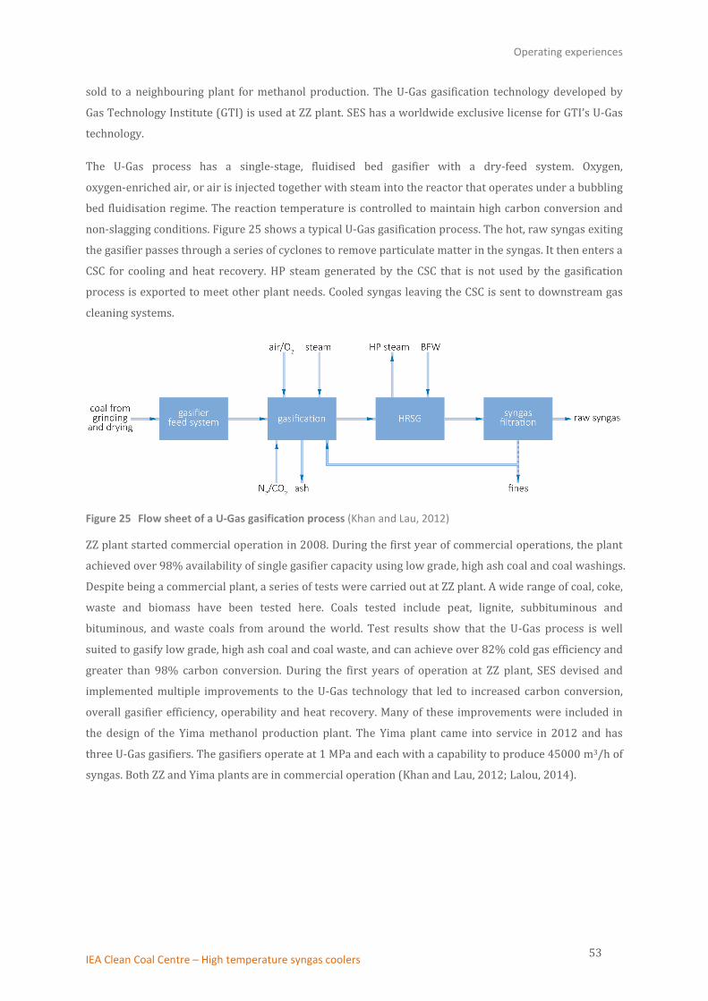
Operating experiences
IEA Clean Coal Centre – High temperature syngas coolers 53
sold to a neighbouring plant for methanol production. The U-Gas gasification technology developed by
Gas Technology Institute (GTI) is used at ZZ plant. SES has a worldwide exclusive license for GTI’s U-Gas
technology.
The U-Gas process has a single-stage, fluidised bed gasifier with a dry-feed system. Oxygen,
oxygen-enriched air, or air is injected together with steam into the reactor that operates under a bubbling
bed fluidisation regime. The reaction temperature is controlled to maintain high carbon conversion and
non-slagging conditions. Figure 25 shows a typical U-Gas gasification process. The hot, raw syngas exiting
the gasifier passes through a series of cyclones to remove particulate matter in the syngas. It then enters a
CSC for cooling and heat recovery. HP steam generated by the CSC that is not used by the gasification
process is exported to meet other plant needs. Cooled syngas leaving the CSC is sent to downstream gas
cleaning systems.
Figure 25 Flow sheet of a U-Gas gasification process (Khan and Lau, 2012)
ZZ plant started commercial operation in 2008. During the first year of commercial operations, the plant
achieved over 98% availability of single gasifier capacity using low grade, high ash coal and coal washings.
Despite being a commercial plant, a series of tests were carried out at ZZ plant. A wide range of coal, coke,
waste and biomass have been tested here. Coals tested include peat, lignite, subbituminous and
bituminous, and waste coals from around the world. Test results show that the U-Gas process is well
suited to gasify low grade, high ash coal and coal waste, and can achieve over 82% cold gas efficiency and
greater than 98% carbon conversion. During the first years of operation at ZZ plant, SES devised and
implemented multiple improvements to the U-Gas technology that led to increased carbon conversion,
overall gasifier efficiency, operability and heat recovery. Many of these improvements were included in
the design of the Yima methanol production plant. The Yima plant came into service in 2012 and has
three U-Gas gasifiers. The gasifiers operate at 1 MPa and each with a capability to produce 45000 m3/h of
syngas. Both ZZ and Yima plants are in commercial operation (Khan and Lau, 2012; Lalou, 2014).

Concluding remarks
IEA Clean Coal Centre – High temperature syngas coolers 54
6 Concluding remarks High temperature syngas can be cooled using a radiant cooler (RSC), convective cooler (CSC),
direct quench cooler or any combination of these coolers. A RSC works at high temperature
(>700°C) and uses radiant heat transfer to cool the hot syngas. Heat is recovered by generating
HP steam. RSC has the tube arrangement similar to that of cylindrical fired boilers where cage
shaped tube panels are used. CSC is usually shell and tube type heat exchanger/boiler consisting
of a set of tubes in a container. Heat is transferred by convection and conduction. Both fire tube
boiler and water tube boiler design have been used for CSC. HP and/or IP steam are generated by
CSC. In a direct quench cooler, the hot raw syngas is rapidly cooled by injection of cooling
medium into the syngas. There are three different direct quenching techniques: water quench,
gas quench and chemical quench. The water quench and gas quench use water and syngas,
respectively, as cooling medium. In chemical quench cooling, the syngas is cooled while the
thermal energy is used to produce other valuable products.
RSC is only used for very high temperature operation and therefore it is usually applied to
entrained flow gasifiers that operate under slagging conditions and produce syngas with
temperatures significantly higher than 1000°C. CSC is generally used to recover heat from
coal-derived syngas with temperatures of 1000°C or lower. There is no heat recovery in water
and gas quenching process.
In general, syngas leaves a gasifier at temperatures in the range of 400°C and 1600°C. The
temperature of the cooled syngas is determined by the operating temperature of the gas cleaning
process immediately downstream of the syngas cooler. It is common that a syngas cooling system
combines different types of syngas coolers. Various syngas cooling systems are in operation in
existing IGCC plants.
Radiant and convective cooling
This design is suitable for cooling hot syngas with temperatures substantially higher than 900°C.
The hot syngas from the gasifier enters a RSC in which it is cooled to a temperature of
approximately 800°C and then flows into CSC for further cooling to desired temperature.
GE Energy has adopted this design as one of the three cooling concepts (radiant and convective
cooling, radiant and quench cooling and total quench cooling) in its slurry feed, downflow,
entrained flow gasification process and has successfully demonstrated this design concept in
Cool Water and Polk IGCC plant. The operating experiences at the two plants show that the
operation of RSC is generally smooth and almost trouble free after the early design and
fabrication defects were corrected. Plugging occurred in CSC and crossover duct that connects
the RSC and CSC and the problems were mitigated by geometric changes.

Concluding remarks
IEA Clean Coal Centre – High temperature syngas coolers 55
Radiant and quench cooling
This design uses a RSC followed by a water quench cooler. Either a full or a partial quench cooler
can be used after the RSC. GE Energy developed a radiant and water quench cooling design in
which the syngas is firstly cooled in a RSC to approximately 800°C. The syngas then flows
through the quench chamber that is located underneath the RSC in the same vessel and is cooled
to around 200–220°C. GE Energy applied this design to the Edwardsport IGCC plant. Due to
various operational issues, as of January 2015, the Edwardsport IGCC plant has been operating
on natural gas rather than coal since its commercial operation started in 2013. Therefore, no
operating experience of the syngas cooling system is reported by the operators.
Siemens has been developing its own radiant and quench cooling design for the Siemens Fuel
Gasification (SFG) process.
Partial quench and convective cooling
In this design, the hot raw syngas is firstly quench cooled to a temperature well below the ash
melting point of the coal, and is then cooled in a CSC. Both Shell’s SCGP and Uhde’s PREFLO
gasification process employ the gas quench and CSC cooling concept although design details are
different. The syngas leaving the gasifier is cooled to a temperature of 800–900°C by mixing
directly with cooled, dust-free recycled syngas of about 230–250°C. The syngas exiting the
quench cooler is further cooled to the desired temperature in CSC. Shell’s cooling system design
was demonstrated in the Buggenum IGCC plant (closed in 2013) in The Netherlands, whilst the
Uhde’s syngas cooling concept has been demonstrated at Puertollano IGCC plant in Spain.
Operations at the two plants provided useful lessons for improvement and optimisation of the
design and operating conditions of the partial quench and convective syngas cooling system.
Entrained-flow, two-stage gasifiers employ chemical quenching in the second-stage gasification.
The sensible heat in the syngas leaving the first stage of the gasifier is used in the endothermic
gasification reactions in the second-stage of gasifier. The syngas exits the gasifier at temperatures
of 1000–1100°C and enters the CSC for cooling and heat recovery. E-Gas, MHI and EAGLE
gasifiers are examples of the entrained-flow, two-stage gasifier with differences in design details.
E-Gas and MHI gasification processes are in commercial operation in Wabash River IGCC (USA)
and Nakoso IGCC plant (Japan), respectively. No major issues regarding the syngas cooling
systems have been experienced in commercial operations of the plants.
Total quench cooling
In total quench cooling, water is sprayed into the quench chamber to cool the hot syngas. There is
no heat recovery in this design and the raw gas exiting the quench cooler is saturated with
moisture. This is one of the three cooling concepts adopted by GE Energy. Total water quench
cooling is a mature technology and it is widely used in gasification plants for production of
chemicals. Shell recently developed a coal gasifier with a bottom water quench cooling system.
Concluding remarks
IEA Clean Coal Centre – High temperature syngas coolers 56
Total quench cooling is reliable and has low capital cost but also results in low overall process
efficiency.
CSC only design
The fluidised bed gasifiers operate at relatively low temperature (900–1100°C) that is high
enough to decompose most of the tar, oils, phenols, and other liquid by-products but lower than
the ash fusion temperature so as to avoid clinker formation. The syngas leaving the gasifier has a
temperature of ~1000°C and is usually cooled in a CSC. CSC with either water tube or fire tube
boiler design can be used. Due to the non-slagging conditions used by fluidised bed gasifiers,
fouling of CSC should be minor. With optimised design and operating conditions, dust deposition
and/or caking, erosion and corrosion in the CSC can be minimised. Several chemical plants in
China operate U-Gas gasifiers (a type of bubbling fluidised bed gasifier) using CSC for high
temperature syngas cooling. This gasification process has been successfully operated on a wide
range of fuels including low grade coal and waste coal.
The selection and design of a syngas cooling and heat recovery system have to consider the
characteristics of the coal feed and syngas produced, the type of gasifier used, the overall
gasification process application and, of course, the costs. The syngas cooler is often one of the
most expensive items in a coal gasification plant. The radiant and convective cooling design can
achieve maximum heat recovery from syngas and hence the highest potential overall process
efficiency. However, the investment cost is significantly higher than the other cooling system
designs. A RSC is an expensive and bulky piece of equipment that only works at high temperature.
CSC is capable of effectively cooling and recovering heat from syngas with relatively low
temperatures ranged from 300°C to 900°C. It also has a smaller footprint than a RSC and has
been employed in various gasification processes. However, compared to RSC and quench coolers,
convective coolers have a higher risk of fouling and plugging which can cause plant outages and
high pressure losses leading to increased downtime and higher maintenance costs.
A total quench cooling system is least energy efficient but has significantly lower capital cost.
When CO2 capture is required, the total quench design has an advantage as the syngas contains a
high water content that is required by the CO shift reaction. Water quench cooling consumes
large quantities of water and requires complex waste water treatment. Other problems
associated with total quench design include discharge water permitting issues, added
operating/maintenance costs and operating problems due to increased water treatment facilities.
Experiences with operating the commercial IGCC plants worldwide, especially the IGCC
demonstration plants, has shown that the syngas cooling system design concepts described
above are sound. Lessons learned from the operations will help to improve and optimise the
designs and operating conditions leading to more efficient, more reliable syngas cooling and heat
recovery systems.

References
IEA Clean Coal Centre – High temperature syngas coolers 57
7 References Alarcón F (2012) Prenflo Gasification Technology–Experiences from Puertollano plant. Available from: http://www.elcogas.es/, Puertollano, Ciudad Real, Spain, ELCOGAS, S.A., 71 pp (Sep 2012)
Alstom (2015) Syngas cooler systems for gasification plants. Company brochure, Levallois-Perret, France, Alstom, 12 pp (2015)
Asano T (2012) Progress in Japanese Air-blown IGCC Demonstration Project Update. Paper presented at: The 7th International Symposium On Coal Combustion, Harbin, P. R. China, 17-20 July 2011. Beijing, P. R. China, Institute of Thermal Engineering, Tsinghua University, 40 pp (Apr 2012)
Ariyapadi S, Shires P, Bhargava M, Ebbern D (2009) KBR’s Transport Gasifier (TRIG™) – an advanced gasification technology for SNG production from low-rank coals. Paper presented at: 25th Annual International Pittsburgh Coal Conference. Pittsburgh, PA, USA, 29 September-02 October 2008. Red Hook, NY, USA, Curran Associates, Inc., Vol. 1, 1 574-591 (Jun 2009)
Barnes I (2013) Recent operating experience and improvement of commercial IGCC. CCC/222, London, UK, IEA Clean Coal Centre, 52 pp (Aug 2013)
Bassett B (2012) Commercially proven Prenflo and High Temperature Winkler Gasification. Paper presented at: 4th EU South Africa Clean Coal Working Group Meeting, Johannesburg, South Africa, 5-6 November 2012. Pretoria, South Africa, Department of Energy, Republic of South Africa, 35 pp (Nov 2012)
Blatchford A (2011) IDGCC Process description, calculation of greenhouse emissions and best practice. ACN 093 163 663, Mulgrave, Victoria, Australia, HRL Developments Pty Ltd, 48 pp (Sep 2011)
Breault R W (2010) Gasification processes old and new: a basic review of the major technologies. Energies, 2010 (3); 216-240 (Feb 2010)
Coca M T (nd) Integrated gasification combined cycle technology: IGCC―its actual application in Spain: ELCOGAS, Puertollano. Available from: http://www.elcogas.es/en/igcc-technology, Puertollano, Spain, Elcogas, 96 pp, last visited (Apr 2015)
Coca-Llano P (2015) Puertollano, Spain, Elcogas, personal communication (Jul 2015)
Cortés C G, Tzimas E, Peteves S D (2009) Technologies for coal based hydrogen and electricity co-production power plants with CO2 capture. JRC Scientific and Technical Report EUR 23661 EN, Brussels, Belgium, Joint Research Centre (JRC), The Institute for Energy, 74 pp (2009)
Dawson K, Thacker P, Hornick M, McDaniel J (2008) TEC to reference plant: toward next generation IGCC plant. Paper presented at: Coal-Gen 2008. Louisville, KY, USA, 13-15 August 2008. Tulsa, OK, USA, PennWell Corporation, 10 pp (2008)
DOE/USACE (2010) Kemper County Integrated Gasification Combined-Cycle (IGCC) Project, Final Environmental Impact Statement. DOE/EIS-0409, Pittsburgh, PA, USA, Department of Energy, National Energy Technology Laboratory, 671 PP (May 2010)
ELCOGAS S.A. (2014) ELCOGAS IGCC plant: clean coal technology–experience and future. Available from: http://www.elcogas.es/, Puertollano, Ciudad Real, Spain, ELCOGAS, S.A., 74 pp (2014)
EPRI (1990) Cool Water Coal Gasification Program: Final Report. EPRI GS-6806, project 1459, Final report, Palo Alto, CA, USA, The Electric Power Research Institute (EPRI) and The Gasification Users Association, 404 pp (Dec 1990)

References
IEA Clean Coal Centre – High temperature syngas coolers 58
EPRI (2006) Gasification Technology Status. Technical Update 1012224, Palo Alto, CA, USA, The Electric Power Research Institute (EPRI) and The Gasification Users Association, 227 pp (Dec 2006)
Fernando R (2008) Coal gasification. CCC/140, London, UK, IEA Clean Coal Centre, 56 pp (Oct 2008)
Fournier G (2009) A water quench for the Shell Coal Gasification Process. Paper presented at: 25th Annual International Pittsburgh Coal Conference. Pittsburgh, PA, USA, 29 September-2 October, 2008. Red Hook, NY, USA, Curran Associates, Inc., Vol. 1, 277-288 (Jun 2009)
de Graaf J D (2008) Shell coal gasification technology. Available from: http://w3.wtb.tue.nl/fileadmin/wtb/ct-pdfs/Energy_from_Biomass/Lecture_2011_gastcollege_Shell.pdf Eindhoven, The Netherlands, Eindhoven University of technology, 34 pp (Sep 2008)
Guenther U (2012) Development and engineering of a synthetic gas cooler concept integrated in a Siemens gasifier design. Paper presented at: 5th International Freiberg Conference on IGCC & XtL Technologies Conference, Leipzig, Saxony, Germany, 21-24 May 2012. Freiberg, Germany, Institute of Energy Process Engineering and Chemical Engineering, 20 pp (2012)
Hashimoto T, Sakamoto K, Ota K, Iwahashi T, Kitagawa Y, Kitagawa K (2010) Development of coal gasification system for producing chemical synthesis source gas. Mitsubishi Heavy Industries Technical Review; 47 (4); 27-32 (Dec 2010)
Higman C (2007) Integrated Gasification Combined Cycle (IGCC) Design Considerations for High Availability—Volume 1: Lessons from Existing Operations. Technical update 1012226, Palo Alto, CA, USA, Electric Power Research Institute (EPRI), 122 pp (Mar 2007)
Higman C, van der Burgt M (2008) Practical issues. In: Gasification-Second edition. Oxford, UK, Gulf Professional Publishing, 193-256 (2008)
H2-IGCC Project (2010) IGCC State-of-the-art report. SP4-System Analysis, Stavanger, Norway, Department of Mechanical and Structural Engineering and Materials Science, University of Stavanger, 91 pp (Apr 2010)
Ishibashi Y (2013) The completion of the air-blown IGCC demonstration test and its conversion to commercial use. Available from: http://www.joban-power.co.jp/igccdata/en/research/pdf/doc/201310_WEC_World_Energy_Council.pdf, Iwaki-shi, Fukusima-ken, Japan, Joban Joint Power Co., Ltd, 13 pp (Oct 2013)
Jenkins S D (1994) Polk Power Station syngas cooling system. Paper presented at: 11th Worldwide Texaco Gasification Licensee Symposium. White Plains, NY, USA, 10-13 October 1994. USA, Texaco, 20 pp (1994)
Keeler C G (2003) Operating experience at the Wabash River Repowering Project. Paper presented at: 2003 Gasification Technologies Conference, San Francisco, CA, USA, 12-15 October 2003. Arlington, VA, USA, Gasification Technologies Council (GTC), 19 pp (2003)
Khan F, Lau F (2012) Demonstrating fuel flexibility in commercial operation. International Journal of Clean Coal and Energy, 2012 (1); 27-33 (May 2012)
Koppel P, Lorden D (2009) Gasification: converting low value feedstocks to high value products. Paper presented at: the 18th Symposium on Industrial Application of Gas Turbines (IAGT). Banff, Alberta, Canada, 19-21 October 2009. Banff, Alberta, Canada, The IAGT Committee, 30 pp (2009)
Kreutz T, Martelli E, Carbo M, Consonni S, Jansen D (2010) Shell gasifier-based coal IGCC with CO2 capture: Partial water quench vs. novel water-gas shift. In: Proceedings of the ASME Turbo Expo; ASME Turbo Expo 2010: Power for Land, Sea, and Air, GT 2010. Glasgow; United Kingdom; 14-18 June 2010. New York, NY, USA, The American Society of Mechanical Engineers (ASME), Vol.1, 583-592 (2010)

References
IEA Clean Coal Centre – High temperature syngas coolers 59
Lalou C (2014) Distributed Power With Advanced Clean Coal Gasification Technology. Cornerstone, 2 (4); 55-60 (Sep 2014)
Liu Y H, Chen W, Che D F, Cao Z D (2010) Comparisons of four quench methods for high temperature syngas-exergy analyses. In: Proceedings of 6th International Symposium on Multiphase flow, Heat Mass Transfer and Energy Conversion. Xian, China, 11-15 July 2009. Melville, NY, USA, AIP Publishing LLC, Vol. 1207; 674-679 (2010)
McCarthy C B, Clark W N (nd) Integrated gasification/combined cycle (IGCC) power production ― A rapidly emerging energy alternative. Available from Fischer-Tropsch Archive at: http://www.fischer-tropsch.org/, Broken Arrow, OK, USA, Emerging Fuels Technology, 22 pp
McDaniel J (2002) Tempa Electric Polk Power Station Integrated Gasification Combined Cycle Project. DE-FC-21-91MC27363 Final report, Tempa, FL, USA, Tempa Electric Company, 260 pp (Aug 2002)
Loney J, Sakamoto K, Iwahashi T (2012) Hydrogen Energy California Update. Paper presented at: The 2012 Gasification Technologies Conference. Washington, DC, USA, 28-31 October 2012. Arlington, VA, USA, Gasification Technologies Council (GTC), 26 pp (2012)
Lorenzo L D, Kreutz T G, Chiesa P, Williams R H (2008) Carbon-free hydrogen and electricity from coal: options for syngas cooling in systems using a hydrogen separation membrane reactor. Journal of Engineering for Gas Turbines and Power, 130 (3); 031401, 10 pp (May 2008)
Nagasaki N, Sasaki K, Suzuki T, Dodo S, Nagaremori F (2013) Near-zero-emission IGCC power plant technology. Hitachi Review, 62 (1); 39-47 (2013)
Ni J, Liang Q, Zhou Z, Zhang Y, Yu G (2009) Multiphase flow and heat transfer in entrained-flow coal gasification radiant syngas cooler. Journal of Chemical Industry and Engineering, 60 (12); 2997-3005 (Dec 2009)
Nunokawa M, Asano T (2014) Progress and utilization of Nakoso 250 MW air-blown IGCC demonstration project. Bulletin of the Japan Society of Mechanical Engineers: Mechanical Engineering Journal; 1 (5); p. 14-00255 (2014)
Payonk R (2008) Wabash River operations update. Paper presented at: 2008 Gasification Technologies Conference, Washington, DC, USA, 5-8 October 2008. Arlington, VA, USA, Gasification Technologies Council (GTC), 17 pp (2008)
Peña F G (2012) Designing gasification processes for high efficiency. Paper presented at: Workshop for 11th European Gasification Conference. Sardinia, Italy, 8-11 May 2012. Rugby, UK, IChemE, 42 pp (2012)
Renzenbrink W, Wischnewski R, Engelhard J, Mittelstädt A (nd) High temperature Winkler (HTW) coal gasification―A fully developed process for methanol and electricity production. Available from: http://www.netl.doe.gov/File%20Library/research/coal/energy%20systems/gasification/gasifipedia/GTC9808P.pdf, National Energy Technology Laboratory (NETL), US Department of Energy (DOE), Pittsburgh, PA, USA, 19 pp, last accessed (Jun 2015)
Rubin E S, Berkenpas M B, Frey H C, Chen C, McCoy S, Zaremsky C J (2007) Development and application of optimal design capability for coal gasification systems. Final report: DE-AC21-92MC29094, National Energy Technology Laboratory (NETL), US Department of Energy (DOE), Pittsburgh, PA, USA, 207 pp (May 2007)
SES (2013) SES U-GAS®气化技术. 中国煤化工, 2013 (13); available from: http://coalchem.org.cn/publication/html/80020816/409.html (Oct 2013)
Siemens (2012) Siemens fuel gasification technology. Brochure for Siemens fuel gasification, available from: www.energy.siemens.com, Erlangen, Germany, Siemens AG, 10 pp (2012)
References
IEA Clean Coal Centre – High temperature syngas coolers 60
Southern Company (2010) Overview of the Kemper County IGCC Project using Transport Integrated Gasification (TRIGTM). Paper presented at: 2010 Gasification Technologies Conference, Washington, DC, USA, 31 October-3 November 2010. Arlington, VA, USA, Gasification Technologies Council (GTC), 18 pp (2010)
Tajima M, Tsunoda J (2002) Development status of the EAGLE gasification pilot plant. Paper presented at: 2002 Gasification Technologies Conference. San Francisco, CA, USA, 27-30 October 2002. Arlington, VA, USA, Gasification Technologies Council (GTC), 11 pp (2002)
TECO (2004) Tampa Electric Integrated Gasification Combined-Cycle Project. Tempa, FL, USA, Tempa Electric Company, 20 pp (Jun 2004)
Thattai A T, Woudstra T, Promes E, Aravind P V (2014) Lessons learnt from the 250 MW IGCC in Buggenum, The Netherlands. Paper presented at: 3rd International Symposium on Solid Oxide Fuel Cells for Next Generation Power Plants: Gasifier - SOFC systems. Warsaw, Poland, 2 June 2014. 32 pp (Jun 2014)
Thyssenkrupp (2015) Gasification technologies. Company Brochure, available from: http://www.thyssenkrupp-industrial-solutions.com/ Essen, Germany, ThyssenKrupp Industrial Solutions, 24 pp, last accessed in April 2015
Uebel K, Guenther U, Hannemann F, Schiffers U, Yilmaz H, Meyer B (2014) Development and engineering of a synthetic gas cooler concept integrated in a Siemens gasifier design. Fuel, 116 (2014); 879–888 (Jan 2014)
van den Berg R, Chen Z X, Chua S H (2014) The Shell coal gasification process for reliable chemicals, power, and liquids production. Cornerstone, 2 (3); 50-54 (Sep 2014)
van Paasen S V B, Xu J, Li X, van den Berg R, Bosch D T (2012) Technology development for Shell coal gasification. Paper presented at: 5th International Freiberg Conference on IGCC & XtL Technologies. Leipzig, Germany, 21-24 May 2012. Freiberg, Germany, The Technical University of Bergakademie Freiberg, 15 pp (2012)
Wabash River Coal Gasification Project Joint Venture/DOE (2000) The Wabash River Coal Gasification Repowering Project. An Update, Topical Report No. 20, Morgantown, WV, USA, National Energy Technology Laboratory (NETL), US DOE, 28 pp (Sep 2000)
Wabash River Energy/US DOE (2000) Wabash River Coal Gasification Repowering Project. Final Technical Report DE-FC21-92MC29310, Morgantown, WV, USA, National Energy Technology Laboratory (NETL), US DOE, 358 pp (Aug 2000)
Watanabe T (2010) Japanese Air Blown IGCC Project Progress. Paper presented at: IGCC Outlook China 2010, Shanghai, China, 15-16 April 2010. 26 pp (2010)
Watanabe T (2012) Brief Introduction on Nakoso IGCC Demonstration plant Technology and its test results. Paper presented at: India Energy Congress 2012, New Delhi, India, 23-24 January 2012. London, UK, World Energy Council (WEC), 26 pp (2012)
Wolters C (2003) Operating Experience at the ‘Willem-Alexander Centrale. GTC Meeting 2003. Available from: http://www.gasification.org/uploads/eventLibrary/19WOLT.pdf, Arlington, VA, USA, Gasification Technologies Council (GTC), 21 pp (Oct 2003)