heat losses engl - pyromasse masonry heater construction · determination of heat losses and...
TRANSCRIPT

SashBatsHomeLabs and stovemaster Batsutin Present
Determination of heat losses and efficiency of the heater, using anemometer and thermocouple
Methodology
Moscow 2009

Determination of heat losses and efficiency of the heater, using anemometr and thermocouple
The simple method of efficiency determination of household heaters is offered and the minimal set of the equipment, allowing it to make, is described. Errors of measurements are estimated. Speed of heat "blowing-out" from the heater after fire is finished is determined with completely open damper and ashbox’s door. The basic formulas used at the analysis of an overall performance of heaters are deduced, the accent on physical sense of expressions and factors is made. The incorrectness of time-averaging of the data received by a gas analyzer, for calculation of efficiency of household heaters of periodic action is shown. For a wide range of interested readers.
THE CONTENTS 1. A theoretical part
1.1 Humidity of wood 1.2 Specific calorific value of wood 1.3 Specific volume of air and exhaust gases 1.4 A heat capacity of air and exhaust gases 1.5 Efficiency of the heater 1.5.1 The analysis of expressions for efficiency 1.5.2 Comparison with Siegert’s formula for gas analyzers, the European standard SN 15250
2. An experimental part
2.1 A heater 2.2 The thermometer 2.3 The anemometer 2.4 The balance 2.5 Carrying out of experiment
3. Processing experimental data
3.1 Correction of the data of speed of entering air 3.2 Calculation of the flow of entering air and its reduction to NTP 3.3 Allocation of the period of burning of fuel and the period of cooling of the furnace 3.4 Calculation of air excess value αavg average and finding of the dependence α from time 3.5 Calculation of heat losses during burning and the overall heater’s efficiency 3.6 Measurement errors estimation 3.7 Calculation of heat losses through open damper and firebox’s door after fire finished
4. Conclusions 5. References 6. Appendix 6.1 Deduction of formulas for calculation of specific volumes of air and exhaust gases 6.2 Deduction of formulas for calculation of efficiency of the heater 6.3 Translation factors of the basic physical values 7. Some facts, found out after this article was written
7.1 Net calorific value of wood by European standard EN 15250 7.2 The maximum concentration of CO2 in exhaust gases and accuracy of air excess determination 7.3 Amendment to NCV - Moisture content formula deduction

1 A THEORETICAL PART Numerical data of calorific value of wood, its dependence on humidity, thermal capacities of departing gases and so forth, brought in the literature are rather inconsistent. In the majority authors do not give references to primary sources, therefore frequently is not clear, this or that figure, the formula or factor whence has undertaken. Therefore in this work we shall deduce all formulas necessary for us «from zero». Absolute values thus can differ a little from literary, but we shall receive full "transparency" of calculations and we shall represent physical sense of all expressions and factors. 1.1 FIREWOOD MOISTURE. Humidity of wood is designated by the letter w and equaled to the relation of weight of the water contained in a sample to weight of absolutely dry wood in this sample [1]. w = mH2O/mdry - moisture, expressed as a decimal fraction or % (1.1) M = mH2O + mdry - weight of a sample, kg (1.2) Mdry = M/(1 + w) - weight of dry wood in a sample in weight of M (1.3) mН2О = Mw/(1 + w) - weight of water in a sample in weight of M (1.4)
Share of dry wood and share of water in a sample accordingly 11 w+
and w1 w+
.
1.2 NET CALORIFIC VALUE OF WOOD. The lowest (net) calorific value (NCV) of fuel is quantity of heat which is emitted at combustion of unit of fuel if water pairs are not condensed in liquid water, and temperature of products of combustion and initial substances is equal 25 0С. Values of net calorific value for absolutely dry wood (w = 0) q0 brought in the literature are strongly differ. Here we shall use value of 4500 kcal/kg = 18810 kJ/kg = 5,23 kWh [1]. Calorific value depends on humidity of wood as, first reduces the contents of dry wood in a sample, and second a moisture which contains in fire wood it is necessary to heat up to 100 0С and evaporate, for what the part of heat is spent. We shall deduce the formula of dependence of calorific value from humidity. Q = q0 · mdry – [с ∆T + qevap] mH2O - heat of combustion of a sample weight of M (1.5) Having divided this expression on M, we shall receive expression for the net calorific value of combustion of wood, humidity w:
( )w 0 evap1q q – c T q w1 w
⎡ ⎤= ∆ +⎣ ⎦+ where (1.6)
w - moisture, expressed as a decimal fraction q0 - net calorific value of wood, 4500 kcal/kg с - heat capacity of water, 1 kcal/kg ∆T - difference of temperatures from 20 up to 100 0С qevap - specific heat of evaporation of water at 100 0С, 540 kcal/kg By substitution of numbers in expression (1.6) we receive:
[ ]w 1q 4500 – 620w1 w
=+
(1.7)
On fig. 1 the dependence of wood NCV from moisture is shown. It is visible, that qw strongly falls with increasing of moisyure. However it is necessary to have in view, that it is dependence by mass unit, and the weight of a sample grows with moisture increasing.

Fig. 1. Dependence of NCV of wood on humidity. Fig. 2. Dependence of losses of heat content of a wood sample during sousing.
The value of qw is used in calculations, and fig. 2 is of interest for the stovemaster (and also the summer
residents and gardeners ☺) 2. It is the graph of dependence0
0
q 620w1 100%q 620 0, 25
⎛ ⎞−λ = −⎜ ⎟− ⋅⎝ ⎠
.
It illustrates the following plausible case - the firewood has been dried up under a canopy up to moisture of 25%, and then we on negligence have wetted it under a rain up to moisture w. The question is - how much heat we shall lose, by burning wet firewood. The paradoxical conclusion turns out at first sight - if to wet it up to 100% we shall lose only 11% of heat. Actually it is because during sousing the weight of dry wood in a sample doesn’t decrease, but only the weight of water and, accordingly, density increases. However everyone knows that if to burn wet firewood, the heater heats much worse. Probably, it is because burning of wet firewood occurs more slowly. Because of the greater heat conductivity, firewood heated up more slowly - more slowly emit volatile components, process is tightened and occurs with the big surplus of air. From here it is possible to draw a conclusion (in general it is banal) - that wet fire wood should to be burn quickly. For example, to warm up the firebox preliminary with dry small firewood, and then put a load of finely splitted wet firewood. Finely splitted (with the increased surface) in order the power of a heat emission will be high and the temperature of firebox’s walls doesn’t reduce. This conclusion correlates with Russian Standard GOST 3000-45 «Heat-capacious heaters, methods of testing», ordering firewood moisture up to 20% to split by logs thickness 9 - 12 cm, and moisture over 20 % - by logs thickness 6 - 9 cm [2]. Wet firewood (as against dry) emits less volatile in the first moments, when new load is putted into hot firebox, due to high heat conductivity and removal of heat inside of logs. We observed this process, burning in bath heater wet firewood - there was no characteristic black smoke within several minutes after putting a new load of firewood. 1.3 SPECIFIC VOLUME OF AIR AND EXHAUST GASES. For calculations we need to know specific (on a mass unit of fuel) volumes of air, required for stoichiometric combustion, and exhaust gases. The deducing of these formulas is shown in the Appendix. All volumes of gases are accepted under normal conditions. Normal (NTP - normal temperature and pressure) are conditions with pressure in 1 atmosphere (101325 Pa) and temperature 273,15K – 0 0C. At NTP the volume of 1 mol of ideal gas is equal to 22,41 liters. So, for absolutely dry firewood specific stoichiometric volume of air is equal to 4.58 nm3/kg, and volume of exhaust gases - 5,22 nm3/kg. The volume of exhaust gases from firewood with moisture w and air excess factor α can be defined by expression:
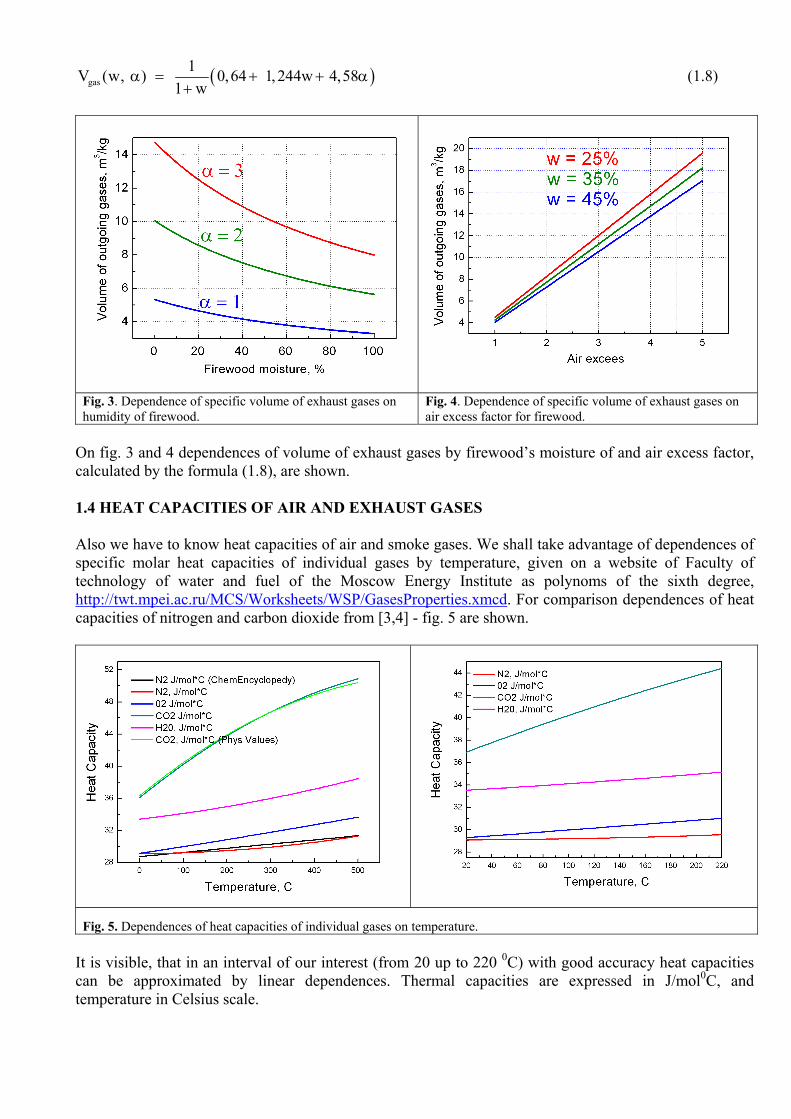
( )gas1V (w, ) 0,64 1,244w 4,58
1 wα = + + α
+ (1.8)
Fig. 3. Dependence of specific volume of exhaust gases on humidity of firewood.
Fig. 4. Dependence of specific volume of exhaust gases on air excess factor for firewood.
On fig. 3 and 4 dependences of volume of exhaust gases by firewood’s moisture of and air excess factor, calculated by the formula (1.8), are shown. 1.4 HEAT CAPACITIES OF AIR AND EXHAUST GASES Also we have to know heat capacities of air and smoke gases. We shall take advantage of dependences of specific molar heat capacities of individual gases by temperature, given on a website of Faculty of technology of water and fuel of the Moscow Energy Institute as polynoms of the sixth degree, http://twt.mpei.ac.ru/MCS/Worksheets/WSP/GasesProperties.xmcd. For comparison dependences of heat capacities of nitrogen and carbon dioxide from [3,4] - fig. 5 are shown.
Fig. 5. Dependences of heat capacities of individual gases on temperature.
It is visible, that in an interval of our interest (from 20 up to 220 0С) with good accuracy heat capacities can be approximated by linear dependences. Thermal capacities are expressed in J/mol0C, and temperature in Celsius scale.

сN2 = 28,97 + 0,00256 T сO2 = 29,11 + 0,00871 T сCO2 = 36,49 + 0,03630 T сH2O = 33,30 + 0,00838 T From here the specific molar heat capacity of air is equal: cair = 0, 79 сN2 + 0,21 сO2 = 29,00 + 0,00385T J/mol0C (1.9) So, increasing of the temperature from 20 up to 200 0С, causes air heat capacity increasing of about 2%. Now let's calculate a heat capacity of stoichiometric composited exhaust gases, formed by combustion of firewood with moisture w. The specific volume of exhaust gases [nm3/kg] (see Appendix) at α = 1 is equal: V0
N2 = 3,62 V0
СО2 = 0,933 VН2О = 0,67 + 1,244w, from here:
wgasc = 0 w
отх H2O
1V wV+
(V0N2сN2 + V0
СО2сO2 + VН2О сH2O) (1.10)
wgasc = 1
5,22 1,244w+[ 161,23 + 0,049Т + w(41,44 + 0,01T) ] (1.11)
On fig. 6 dependences of heat capacities of the exhaust gases, calculated by (1.11) and air (1.9) by temperature are shown. Units of heat capacity are J/mol0C. Recalculation of the heat capacity to normal cubic meter can be made like this:
[ ]
3
3 0
1000 l / nmJ Jc сnm C mol C 22.41 l / mol
⎡ ⎤⎡ ⎤ ⎡ ⎤ ⎣ ⎦= ⋅⎢ ⎥ ⎢ ⎥⎣ ⎦ ⎣ ⎦
The factor 22,41 [l/mol] is called the molar volume of gases at NTP, 1000 – quantity of liters in cubic meter.
1.5 HEATER’S EFFICIENCY The efficiency of the heater η is a relation of quantity of heat absorbed by the heater to the total amount of heat emitted from fuel burning. We shall assume, that all heat absorbed by the heater, will be transferred to a room during the period of heat transfer, i.e. the heater is on an operating mode. We shall neglect mechanical and chemical underburning. Efficiency can be expressed in shares of unit or in percentage, what is more habitual. The value (1 – η) is called the relative losses and defined as the relation of quantity of heat left to a chimney to the total amount of heat emitted from fuel burning. Basically we shall use (1 – η) value as it simplifies mathematical expressions. It is possible to distinguish two kinds of efficiency (and losses accordingly) - integrated, that is the general efficiency during the period of time ∆t, and current efficiency, at the moment of time t.
Fig. 6. Dependences of heat capacities of air and exhaust gases (at α = 1) by temperature and firewood’s moisture.

Integrated efficiency for the period of time ∆t = t2 – t1 can be determined by the formula:
1- η = 2
1
t
gaswt
1 W (t)dtMq ∫ (1.12)
Current efficiency, at the moment of time t:
1- ηt = gas
burn
W (t)W (t)
where (1.13)
Wgas(t) - heat power of losses with exhaust gases flow, W Wburn (t) - heat power emitted by fuel burning, W M - weight of burned fuel, kg qw - NCV of fuel with moisture w, J/kg.
When speak about efficiency of the heater, as heating device an integrated value (1.12) is used. For its determination, it is necessary to know any absolute value - gases flow or burning speed. On the contrary, for determination of current efficiency (1.13) it is unessential to know absolute values, enough only relative - for example air excess factor. The value ηt shows the efficiency of heat absorption process by the heater regardless to absolute its amount. And it is very important to notice, that integrated efficiency η cannot be received by time-averaging of ηt value. Efficiency is not an additive value. We shall explain it on an example - fig. 7. Let in the
heater burns fuel, and burning power is shown in figure by a black line. The useful power spent on heating of the heater - a red line. Red shading - it is heat, absorbed by the heater. Obviously, that integrated efficiency η of the heater will be equal to relation of the areas under these curves (red to black). However, values of ηt vary during burning process in our hypothetical heater from 90% to 10%, and the period of time with ηt = 10% in 5 times more. In result, time-averaging of ηt gives value of 23,3% while real efficiency makes 63,3%. As the saying goes [5] - identical to identical – two big differences! Average ηt and integrated efficiency can coincide, only if power of heat emission in firebox does not vary by time, for example in industrial furnaces of continuous action where it is set by a stream of fuel, or value of ηt is constant. Or they can coincide for the casual reasons. Application of time-averaged ηt for an estimation of household heaters efficiency isn’t correct, because power of heat emission in firebox varies over a wide range. The value of ηt can be applied for optimization of heater’s work, for adjustments during burning process. For the same reasons time-averaging of other relative values – air excess factor α and carbon monoxide concentration [CO] in exhaust gases is incorrect also. At such averaging one big peak of emission [CO] can cross out all clean burning, though absolute amount of CO in the peak can be negligibly little in comparison with the total emitted amount. The emission of CO the household heaters of periodic action is desirable to estimate by calculation its absolute amount and then calculate it’s average concentration during firing period, or to recount for continuous work of the heater. And it is even better - on a mass unit
Fig. 7. An illustration of an incorrectness of time-averaging of current efficiency values.
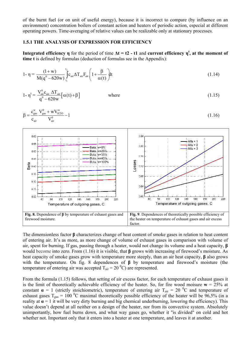
of the burnt fuel (or on unit of useful energy), because it is incorrect to compare (by influence on an environment) concentration boilers of constant action and heaters of periodic action, especial at different operating powers. Time-averaging of relative values can be realizable only at stationary processes. 1.5.1 THE ANALYSIS OF EXPRESSION FOR EFFICIENCY Integrated efficiency η for the period of time ∆t = t2 - t1 and current efficiency ηt, at the moment of time t is defined by formulas (deduction of formulas see in the Appendix):
1- η = 2
1
t
air air air0t
(1 w) с Т F 1 dtM(q 620w) (t)
⎛ ⎞+ β∆ +⎜ ⎟− α⎝ ⎠
∫ (1.14)
1- ηt = [ ]0air air air0
V с Т (t)q 620w
∆α +β
− where (1.15)
w 0 wgas gas H2O
0air air
c V wV1
с V+
β = − (1.16)
The dimensionless factor β characterizes change of heat content of smoke gases in relation to heat content of entering air. It’s as more, as more change of volume of exhaust gases in comparison with volume of air, spent for burning. If gas, passing through a heater, would not change its volume and a heat capacity, β would become into zero. From (1.16) it is visible, that β grows with increasing of firewood’s moisture. As heat capacity of smoke gases grow with temperature more steeply, than an air heat capacity, β also grows with the temperature. On fig. 8 dependences of β by temperature and firewood’s moisture (the temperature of entering air was accepted Tair = 20 0С) are represented. From the formula (1.15) follows, that setting of air excess factor, for each temperature of exhaust gases it is the limit of theoretically achievable efficiency of the heater. So, for fire wood moisure w = 25% at constant α = 1 (strictly stoichiometric), temperature of entering air Tair = 20 0С and temperature of exhaust gases Tgas = 100 0С maximal theoretically possible efficiency of the heater will be 96,5% (in a reality at α = 1 it will be very dirty burning and big chemical underburning, lowering the efficiency). This value doesn’t depend at all neither on a design of the heater, nor from its convective system. Absolutely unimportantly, how fuel burns down, and what way gases go, whether it "is divided" on cold and hot whether not. Important only that it enters into a heater at one temperature, and leaves it at another.
Fig. 8. Dependence of β by temperature of exhaust gases and firewood moisture.
Fig. 9. Dependences of theoretically possible efficiency of the heater on temperature of exhaust gases and air excess factor.

On fig. 9 dependences of relative losses (1-η) by Tair and air excess factor α are represented. Thus, for example, if we set α = 2, providing more - less full combustion of firewood (and hold this value constant during burning process) and temperature of exhaust gases Tgas = 140 0С, providing steady draw in a chimney and absence of water condensation - efficiency of such heater will not exceed 90,7% in principle. In view of above-stated, periodically messages from some researchers about achievement of heater’s efficiency of 90 and over percent sound rather revolutionary. This information can be useful at an estimation and comparison of experimental data. If dependences on fig. 9 will be continued in high temperature area, at the certain temperature the value of losses will reach unit. This temperature named the maximal calorimetric temperature of burning. It corresponds to a case when all heat, emitted by burning, is spent for heating of combustion products. (At determination of the maximal temperature of burning it is impossible to use linear dependences of heat capacities on temperature.) Comparing (1.14) and (1.15) it is interesting to note, that in expression for current efficiency (1.15) there is no multiplier (1 + w) causing strong dependence of result from fuel’s moisture. It occurs because ηt is a relative value, and (1 + w), as well as weight M, specify an absolute quantity of dry wood in a sample. In (1.14) both multipliers are present. 1.5.2 COMPARISON WITH SIEGERT’S FORMULA FOR GAS ANALYZERS The current value of related losses with exhaust gases 1-ηt can be calculated by determination of exhaust gases composition by gas-analyzer. The majority of simple devices determinate the following values: temperature of entering air and smoke gases, volumetric concentration of oxygen [O2] and carbon monoxide [CO] in smoke gases, all other values turn out by calculation. For related losses calculation empirical Siegert’s formula (1.17) is used, and more suitable name is applied to the value of efficiency ηt - the operating ratio of fuel. The amendment on chemical underburning by CO contents also can be made, but as a rule, it is negligibly small.
gas airA1q (T T ) B[X]⎛ ⎞
= − +⎜ ⎟⎝ ⎠
where (1.17)
q - related losses, % Tgas, Tair - temperature of entering air and exhaust gases A1, B - factors, depending of kind of fuel [X] - concentration of CO2 or [О2]max - О2 in smoke gases, (depending on the manufacturer). For some reasons factors А1 and B for the same kind of fuel differ for the different countries, in tab. 1 their values are represented. Also some manufacturers (MRU, Madur electronics) calculate losses by [CO2] and others (TESTO) by [O2]. As concentration [X] = [X]max/α expression (1.17) can be rewritten as:
maxB[X]A1q T[X] A1
⎛ ⎞= ∆ α +⎜ ⎟⎝ ⎠
(1.18)
Attentively having looked on (1.18) it is easy to notice similarity with (1.15), so:
0air air
0max
V с A1 100% A[X] q 620w
= ⋅ =−
и w 0gas gas H2Omax
0air air
c V wVB[X] 1A1 с V
⎡ ⎤+= − = β⎢ ⎥⎢ ⎥⎣ ⎦
(1.19)

Let's calculate factors A and β, by (1.19) accepting an air heat capacity at 150 0С and NCV of absolutely dry wood q0 = 4500 kcal/kg and compare them with the values given by gas-analyzers manufacturers.
АW=0% = 0 150Cair air
0
V сq 620w−
= [ ] [ ]
3 0 3
3
4,58 nm / kg 29,57 J / mol C) 44,64 mol / nm4500*10 сal / kg 4,184 J / сal
⎡ ⎤ ⎡ ⎤ ⎡ ⎤⎣ ⎦ ⎣ ⎦ ⎣ ⎦ 100% = 0,0321 0
1С
⎡ ⎤⎢ ⎥⎣ ⎦
Factor β we shall calculate for temperature 150 0С in view of dependence of gases heat capacities on temperature, applying integration, (see. A2.10, A2.11 and fig. 8). For full comparison of the data we shall calculate also maximal concentration of carbon monoxide [CO2]max in smoke gases, depending of firewood’s moisture (see. Appendix). Manufacturer/Country A1 B [CO2]max [X] A·102 β MRU Russia, Austria, Belgium, Fr, GB, Italia 0,60 0,009 19,4 [CO2] 3,09 0,291 D, Czech, Norway, Poland, Slovenia 0,60 0,009 20,5 [CO2] 2,92 0,308 USA 0,60 0,020 19,4 [CO2] 3,09 0,647 Madur Electronics 0,65 0 19,4 [CO2] 3,35 0 TESTO 0,765 0 20,3 [O2]max-[O2] 3,64 0
Fofmula (1.19), q0 = 4500 kcal/kg, V0air = 4,58 nm3/kg, V0
gas = 5,22 nm3/kg w = 0 % 17,9 3,21 0,231 w = 25 % 16,9 3,33 0,309 w = 100 % 14,4 3,72 0,547
European Standard SN 15250 Fofmula (1.19), q0 = 5338 kcal/kg, V0
air = 4,69 nm3/kg, V0gas = 5,34 nm3/kg
w = 0 % 17,5 2,77 0,234 w = 25 % 16,5 2,86 0,306 w = 100 % 14,2 3,14 0,521 Tab. 1. The summary table for Siegert’s factors for firewood.
Now we can make charts of manufacturers of gas-analyzers. The first that can be noticed - all manufacturers take wood with the contents of carbon more than 50%, and with the minimal moisture content. Moreover, it is not clear as in exhaust gases during burning wood can contain, for example 20,3% CO2. The structure of such wood should be approximately following - C1(H2O)0,17 or by weight C:H:O = 80:2,5:17,5. This means 80% (!) of carbon content at the best case, in consideration, that there is no «free» hydrogen in firewood. 19,4% CO2 concentration corresponds the contents of carbon of 63 % and more. It is possible to assume, that such overestimated values of [CO2]max are cause by the fact that at wood burn-down stages a pure carbon is forming. But in such case this parameter is senseless at all. Integrally, the most adequate values of factors are given by MRU for the European countries. It is difficult to say, what causes some difference of factors – probably the other structure of wood was accepted (V0
air depends of structure), or/and other NCV was used. Zeroing of factor β in TESTO devices and Madur Electronics can be justified only if air excess factor is high, and generally incorrect. For finding-out of a question about firewood’s NCV and air specific volume V0
air we turn attention to European Standard EN 15250 [6], tab. 2. It is significant; that the standard separates fuel, for commercial use and fuel with the setted structure for heater’s testing. However NCV for standard firewood q0 by some reason is not represented. From the given data of NCV, having made the amendment on moisture, it is possible to calculate q0. From tab. 2 it is visible, that q0 given in this standard considerably exceeds the values accepted in the Russian literature (approx. 4500 kcal/kg [1,2]) - 20% free-of-charge for the whole family! Specific stoichiometric volume of air V0
air considerably varies by vary of wood structure,
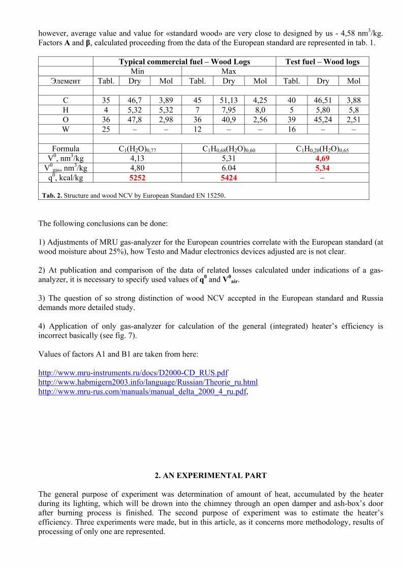
however, average value and value for «standard wood» are very close to designed by us - 4,58 nm3/kg. Factors A and β, calculated proceeding from the data of the European standard are represented in tab. 1. Typical commercial fuel – Wood Logs Test fuel – Wood logs Min Max Элемент Tabl. Dry Mol Tabl. Dry Mol Tabl. Dry Mol
C 35 46,7 3,89 45 51,13 4,25 40 46,51 3,88 H 4 5,32 5,32 7 7,95 8,0 5 5,80 5,8 O 36 47,8 2,98 36 40,9 2,56 39 45,24 2,51 W 25 – – 12 – – 16 – –
Formula C1(H2O)0,77 C1H0,68(H2O)0,60 C1H0,20(H2O)0,65
V0, nm3/kg 4,13 5,31 4,69 V0
gas, nm3/kg 4,80 6.04 5,34 q0, kcal/kg 5252 5424 –
Tab. 2. Structure and wood NCV by European Standard EN 15250.
The following conclusions can be done: 1) Adjustments of MRU gas-analyzer for the European countries correlate with the European standard (at wood moisture about 25%), how Testo and Madur electronics devices adjusted are is not clear. 2) At publication and comparison of the data of related losses calculated under indications of a gas-analyzer, it is necessary to specify used values of q0 and V0
air. 3) The question of so strong distinction of wood NCV accepted in the European standard and Russia demands more detailed study. 4) Application of only gas-analyzer for calculation of the general (integrated) heater’s efficiency is incorrect basically (see fig. 7). Values of factors A1 and B1 are taken from here: http://www.mru-instruments.ru/docs/D2000-CD_RUS.pdf http://www.habmigern2003.info/language/Russian/Theorie_ru.html http://www.mru-rus.com/manuals/manual_delta_2000_4_ru.pdf,
2. AN EXPERIMENTAL PART The general purpose of experiment was determination of amount of heat, accumulated by the heater during its lighting, which will be drown into the chimney through an open damper and ash-box’s door after burning process is finished. The second purpose of experiment was to estimate the heater’s efficiency. Three experiments were made, but in this article, as it concerns more methodology, results of processing of only one are represented.

2.1 А HEATER
Fig. 10. A heater during experiment, the front view.
Fig. 11. A heater, the rear view. Fig. 12. Varsik participated in scientific in research actively.
The heater «Teplushka» fig. 10 - 12 with an additional bel atop of the vault has been constructed by us in the summer of 2005. Last two years it is used constantly and is the basic source of heat in the house, along with the other heater. The house is for constant residing, food prepares exclusively, using the heater, there are no electric or gas cookstoves in the house. The sizes of the heater are 5½ on 5½ bricks (1,4*1,4 m), height 33 rows. The heater stands in a pier between rooms, on the second floor one more heater stands upon it. Basic parameters of the heater – firebox width - 25 cm, grate bar size - 25*38 cm, chimney’s section from heater’s top up to the middle of an attic 25*13 cm, from the middle of an attic up to the chimney’s end - 38*13 cm (on an attic both chimneys from two heaters are incorporated). Chimney’s height from a floor is about 14 meters. Width of inlets: in the channel from the bottom chamber - 2 rows of 13 cm + 3 rows of 13 cm, in a chimney from the bell - 2 rows of 25 cm. We will not consider more details of the heaters design in this article, because it is not of great importance. The article has more methodological character; we do not set as the purpose to determine parameters particularly of this heater. 2.2 THE THERMOMETER
Temperature of smoke gases was measured by the K-type thermocouple (chromel - alumel), connected to digital multimeter М838 with temperature measuring function, manufactured by MASTECH http://www.p-mastech.com, fig. 13. Temperature measurement’s accuracy by the passport consists: -20... + 150 0C ± (3 % + 2D) +150 … 1370 0C ± 3 % 2D means two units of the lower digit. As the device resolution - 1 0C, 2D = 2 0C. So, for example, if indicated value is 100 0C the manufacturer guarantees, that true value of temperature is within the limits of 100 ± (100*0,03+2) = 95 … 105 0C. If on a panel 200 0C the true value is in limits 194 … 204 0C. For precisely temperature measurements with thermocouple it is necessary to store its cold junction at the certain temperature (frequently used a mix water - ice), and measure its EMF, which makes few millivolts and after
Fig. 13. A digital multimeter М838 and the K-type thermocouple.

to convert EMF into temperature by calibrating table. The majority of simple multimeters realize the simplified algorithm, as causes the high measurement’s errors. Checkup of the device was made by measuring of boiling water and ice fusion temperatures; it consisted + 98 0C and + 2 0C accordingly, the device was at room temperature. Any amendments to instrument readings during calculations were not applied. The thermocouple applied in the complete set to the device though it is designed for use at high temperatures, has internal isolation from plastic, which starts to fuse at temperatures over 150 0C. Therefore it has been replaced by another, same K - type, but in glass-fiber isolation (has yellow plug and enter into the complete set of more expensive multimeters, but is accessible separately). The device with the thermocouple can be got in radio electronics shops, for example the Chip&Dip www.chip-dip.ru, the estimated price in November, 2009 was 500 RUR. 2.3 THE ANEMOMETR
Fig. 14. Anemometer Skywatch Xplorer 2. On a back metal cover of the device glued thermoresistor can be seen.
Measurements of entering air flow speed were made by impeller-type thermo-anemometer Skywatch Xplorer 2 Swiss produced by JDC Electronic SA, http://www.jdc.ch. The device fig. 14 is intended for measurement of wind speed during sport outdoor activities and designed as waterproof device. It can carry the immersing into water on depth up to 1 m. Opening of the device has pleasantly surprised with accuracy and quality of installation. To a back metal cover of the device by heat-conducting paste thermoresistor is glued, measuring an ambient temperature. At such arrangement of the gauge, sluggishness can be expected, but the device rather quickly reacted to drafts on a floor from the open doors. Rotation velocity sensor is designed with electromagnetic coupling - the constant magnet is built in impeller – and in the electronic circuit - inductance. Such decision allowed making easily the device in waterproof design. But this decision has a bug - the magnet in impeller shows appreciable resistance to rotation (appreciable at small wind speeds, less to sensitivity of the device) - impeller aspires to occupy the certain position. As a result - at speeds of a wind less than 0,6 - 0,7 m/s the device works unstably, and it is possible to define these values as response limit. Other important feature is that the closeness of metal objects has an influence to instrument readings. Therefore for measurement of speed of a flow of heater’s entering air taking out the device from a zone of influence of metal frameworks (firebox door) is necessary. For example it can be made with the help of cardboard box (fig. 18), length 40 - 50 cm. Calibration of the device was not made. The accuracy declared by the manufacturer is ± 3 %, a range 0 - 42 km/s. The resolution - 0,1 m/s. Price of the device in September, 2009 in http://www.kites.ru was 2350 RUR. Skywatch Xplorer 1 (without temperature sensor) it is possible to get for 1800 RUR.

2.4 THE BALANCE
Fig. 15. Dial household balance VBC - 10 BKZI. 4044471.001 TU. Fig. 16. A complete set.
For firewood’s weight determination dial household balance VBC - 10 BKZI. 4044471.001 TU, manufactured by Joint-Stock Company «Cheboksarskii electrohardware factory» http://www.cheaz.ru was used. Balance fig. 15 is intended for definition of weight of cargoes in domestic conditions. The powerful steel hook with the pointed end for fixing cargoes causes respect for the Manufacturer. The convenient metal ring allows making measurements one by one, achieving high speeds of weighing. Gauging is carried out manually - by turning of a protective glass with the index mark. The attribute of the device is curved dial and absence of its fixing on an axis of rotation in a longitudinal direction. It leads to grazing of dial to a protective glass and to its periodic jamming; in this connection, indications can differ on 0,2 - 0,4 kg, depending on from what side the dial approaches to the index risk. For value of weight average value of a series from 5 - 7 weightings was accepted. More progressive way is use of the device without a protective glass. Calibration of the device was not made. The device is accessible in retail set and is delivered in a colorful cardboard box with original design. The estimated price of the device in the Moscow markets for September, 2009 was 130 RUR. 2.5. CARRYING OUT OF EXPERIMENT Experiment was carried out as follows. All pieces of firewood has been loaded in a firebox at once and lighted from below. After 30 minutes firewood were moved with a rabble for more dense stacking embers on a grate-bar. No more any adjustments of burning process were made. A damper and ashbox’s door were completely open during all experiment. The following values were recorded: the temperature of smoke gases Tgas, temperature and speed of entering air (Tair and vair). The thermocouple for Tgas measurement has been established in the middle of section of a chimney, above the damper. The temperature of entering air was measured by anemometer’s built - in thermometer. Anemometer fig. 18 has been established on an entrance of cardboard box, inserted in a ashbox’s door frame. During burning firebox door was closed by the roofing steel screen (fig. 12) for protection cardboard box from heating. All data were recorded manually every 5 minutes; during burning and during 3 hours after it was finished. Experimental conditions Date and time 4.10.2009, 10.00 - 13.45 Temperature in the street in the beginning of experience +6 Temperature in the street at the end of experience +10 Weak wind, sometimes impulses of a wind.

As fuel birch logs, fig. 17 were used. Moisture of firewood was not measured in view of absence of the corresponding device. Presumably firewood have been prepared in summer of this year and dried under a canopy. Directly before experiments firewood were kept 2 day on a shelf in a bath house at temperature 60 - 80 0С and then within 2 weeks were stored in the room. At all calculations firewood’s moisture was accepted 25%. Weight of firewood M = 12,8 kg; NCV qw = 3476 kcal/kg Firewood’s total heat content qwM = 12,8*4,184*3476 = 185980 kJ = (/3600) = 51,7 kWh Required stoichiometric air volume MV0
air/ (1+w) = 12,8 * 4,58 / (1+0.25) = 46,9 nm3 Burning process characteristics (calculation) Time of burning - from 5 for 35 minute ∆t = 30 minutes Average heat power of burning Wburn avr = qwM/∆t = 103 kW Volume of entered air during active burning total
airV = 104 nm3 Average air excess factor αavr = 104/46,9 = 2,21
3. PROCESSING OF EXPERIMENTAL DATA Processing of experimental data was carried out using the program MicroCal ORIGIN 7.5 Pro in the following sequence:
1) Correction of the data of speed of entering air with the purpose of removing of misses 2) Calculation of the entering air flow and its reduction to NTP 3) Separation of the period of firewood burning and the period of the heater’s cooling 4) Calculation of air excess value αavr average
and finding of the dependence α from time 5) Calculation of value of heat losses during burning by numerical integration and calculation of
heater’s overall efficiency 6) Measurement errors estimation 7) Calculation of heat losses through open damper and ashbox’s door after fire is finished
Fig. 17. Birch chocks, 13 pieces. The weight of 12,8 kg, moisture is unknown.
Fig. 18. Cardboard box with anemometer.
3.1 Correction of the data of speed of entering air with the purpose of removing of misses
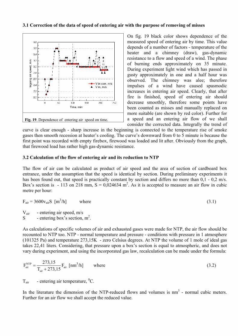
On fig. 19 black color shows dependence of the measured speed of entering air by time. This value depends of a number of factors - temperature of the heater and a chimney (draw), gas-dynamic resistance to a flow and speed of a wind. The phase of burning ends approximately on 35 minute. During experiment light wind which has passed in gusty approximately in one and a half hour was observed. The chimney was alee; therefore impulses of a wind have caused spasmodic increases in entering air speed. Clearly, that after fire is finished, speed of entering air should decrease smoothly, therefore some points have been counted as misses and manually replaced on more suitable (are shown by red color). Further for a speed and an entering air flow of we shall consider the corrected data. Integrally the trend of
curve is clear enough - sharp increase in the beginning is connected to the temperature rise of smoke gases then smooth recession at heater’s cooling. The curve’s downward from 0 to 5 minute is because the first point was recorded with empty firebox, firewood was loaded and lit after. Obviously from the graph, that firewood load has rather high gas-dynamic resistance. 3.2 Calculation of the flow of entering air and its reduction to NTP The flow of air can be calculated as product of air speed and the area of section of cardboard box entrance, under the assumption that the speed is identical by section. During preliminary experiments it has been found out, that speed is practically constant by section and differs no more than 0,1 - 0,2 m/s. Box’s section is - 113 on 218 mm, S = 0,024634 m2. As it is accepted to measure an air flow in cubic metre per hour: Fair = 3600vairS [m3/h] where (3.1) Vair - entering air speed, m/s S - entering box’s section, m2. As calculations of specific volumes of air and exhausted gases were made for NTP, the air flow should be recounted to NTP too. NTP - normal temperature and pressure - conditions with pressure in 1 atmosphere (101325 Pa) and temperature 273,15K - zero Celsius degrees. At NTP the volume of 1 mole of ideal gas takes 22,41 liters. Considering, that pressure upon a box’s section is equal to atmospheric, and does not vary during experiment, and using the incorporated gas law, recalculation can be made under the formula:
NTPair air
air
273,15F FT 273,15
=+
[nm3/h] where (3.2)
Tair - entering air temperature, 0C. In the literature the dimension of the NTP-reduced flows and volumes is nm3 - normal cubic meters. Further for an air flow we shall accept the reduced value.
Fig. 19. Dependence of entering air speed on time.
3.3 Separation of the period of firewood burning and the period of the heater’s cooling-down
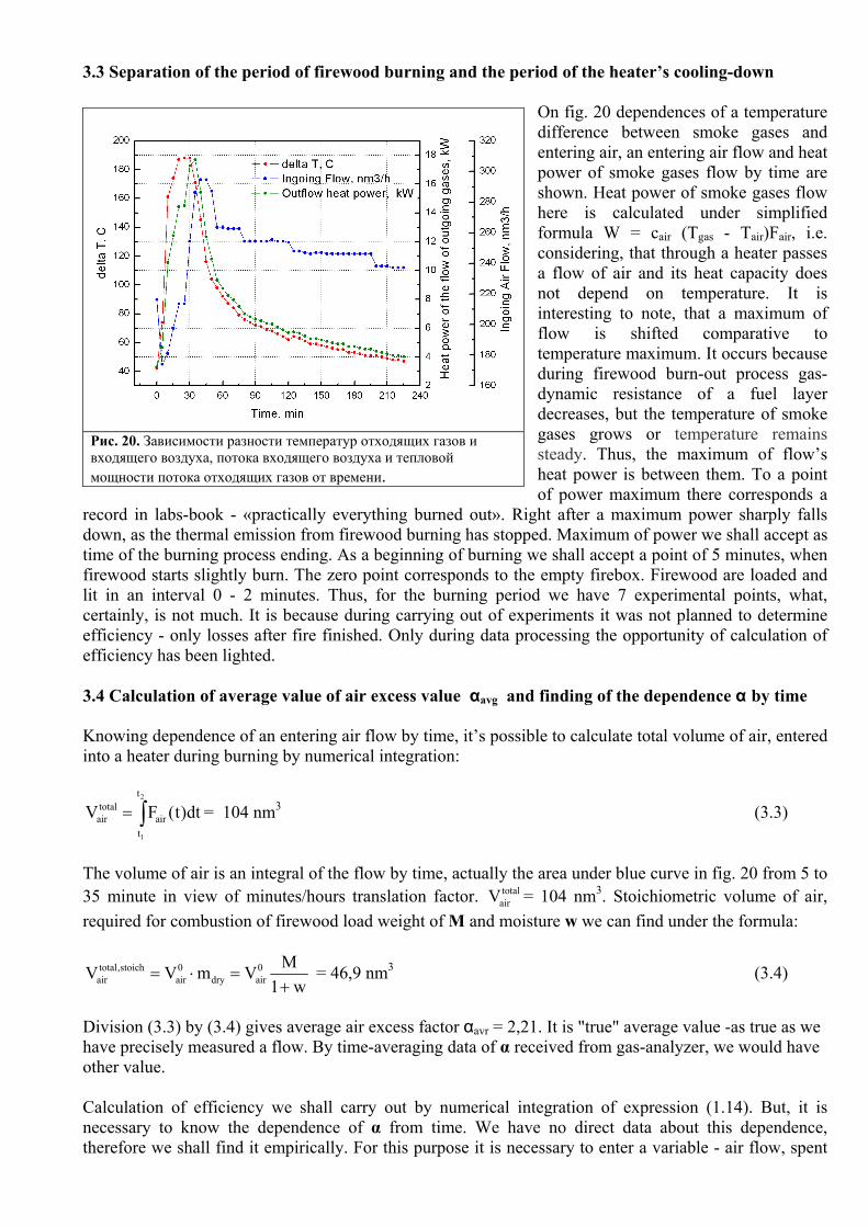
On fig. 20 dependences of a temperature difference between smoke gases and entering air, an entering air flow and heat power of smoke gases flow by time are shown. Heat power of smoke gases flow here is calculated under simplified formula W = cair (Tgas - Tair)Fair, i.e. considering, that through a heater passes a flow of air and its heat capacity does not depend on temperature. It is interesting to note, that a maximum of flow is shifted comparative to temperature maximum. It occurs because during firewood burn-out process gas-dynamic resistance of a fuel layer decreases, but the temperature of smoke gases grows or temperature remains steady. Thus, the maximum of flow’s heat power is between them. To a point of power maximum there corresponds a
record in labs-book - «practically everything burned out». Right after a maximum power sharply falls down, as the thermal emission from firewood burning has stopped. Maximum of power we shall accept as time of the burning process ending. As a beginning of burning we shall accept a point of 5 minutes, when firewood starts slightly burn. The zero point corresponds to the empty firebox. Firewood are loaded and lit in an interval 0 - 2 minutes. Thus, for the burning period we have 7 experimental points, what, certainly, is not much. It is because during carrying out of experiments it was not planned to determine efficiency - only losses after fire finished. Only during data processing the opportunity of calculation of efficiency has been lighted. 3.4 Calculation of average value of air excess value αavg and finding of the dependence α by time Knowing dependence of an entering air flow by time, it’s possible to calculate total volume of air, entered into a heater during burning by numerical integration:
2
1
ttotalair air
t
V F (t)dt= ∫ = 104 nm3 (3.3)
The volume of air is an integral of the flow by time, actually the area under blue curve in fig. 20 from 5 to 35 minute in view of minutes/hours translation factor. total
airV = 104 nm3. Stoichiometric volume of air, required for combustion of firewood load weight of M and moisture w we can find under the formula:
total,stoich 0 0air air dry air
MV V m V1 w
= ⋅ =+
= 46,9 nm3 (3.4)
Division (3.3) by (3.4) gives average air excess factor αavr = 2,21. It is "true" average value -as true as we have precisely measured a flow. By time-averaging data of α received from gas-analyzer, we would have other value. Calculation of efficiency we shall carry out by numerical integration of expression (1.14). But, it is necessary to know the dependence of α from time. We have no direct data about this dependence, therefore we shall find it empirically. For this purpose it is necessary to enter a variable - air flow, spent
Рис. 20. Зависимости разности температур отходящих газов и входящего воздуха, потока входящего воздуха и тепловой мощности потока отходящих газов от времени.

for burning burnairF (t) - by definition this flow in α time less than entering air flow. It is obvious, that this
flow at all moments of time is less (or is equal) to entering air flow as 1α ≥ . And at last, the integral of this flow by time is equal to total,stoich
airV = 46,9 нм3. Mathematically it can be written by expressions (3.5), (3.6) and (3.7):
burnair air
1F (t) F (t)(t)
=α
(3.5)
burnair burnF (t) F (t)≤ (3.6)
2
1
tburn 0air air
t
MF (t)dt V1 w
=+∫ (3.7)
Let's find burn
airF (t) , that it has satisfied to conditions (3.6) and (3.7), and dependence of α(t) we shall receive from expression (3.5). This task is convenient for graphically solving.
Fig. 21. Entering air flow (a grey curve) and probable dependences of a flow of air spent for burning (black and color curves).
Fig. 22. Probable dependences of air excess factor α from time. Red number - the erroneous value of losses calculated by time-averaging of instant values. Black numbers -real losses in kWh.
On fig. 21 dependences of an entering air flow Fair(t) (a grey curve) and probable flows of air spent for burning burn
airF (t) - black and color curves are shown. X-coordinate is burning time, a point of "0" is corresponds to 5 minute of experiment. For a base line we shall accept constant burn
airF (t) = total,stoichairV /∆t =
46,9 nm3/0,5 hour = 93,8 nm3/hour (a black straight line). All other probable curves of dependences of flows will "be twisted" around of this line, but the areas under them must be equal total,stoich
airV = 46,9 nm3. Also they will not rise above a grey curve. Various geometrical and algebraic ways of a finding of these dependences are possible. We shall stop on physical sense burn
airF (t) . This flow (actually it is speed of air burning) is proportional to firewood’s burning speed:
burn burnwood air0
air
1 wv (t) F (t)V+
= (3.8)
Thus, the curve burn
airF (t) shows as well a mode of dependence of fuel speed burning by time. Now, knowing it, it is possible to assume, what curves of dependences burn
airF (t) plotted by us are more real, and which are physically senseless at all. So, for example, clearly, that the blue curve on fig. 21 is deprived of physical sense, as burning speed should generally fall, especially to the end of burning process, as the

amount of the fuel and its surface decrease. So, generally dependencies of fuel burning speed (as well as burnairF (t) will have probably the following mode: sharp increase (start of fuel burning) and then smooth
recession - burning and burning-down. In our case time is counted from 5 minute of experiment (the start-burning moment is missed) and it is logically to assume, that burning speed will just falls down. Now, having dependences burn
airF (t) it is possible to plot (from 3.5) dependences of air excess factor α(t) by time for each case, fig. 22. From figure it is visible, that the curve Alfa_1, corresponding to a linear recession of burning speed, is most similar to literary experimental data. For comparison, on fig. 23 typical dependence of α by time, received by a gas-analyzer (experiment from 08.02.2007, load#2, [7]) is shown.
3.5 Calculation of value of heat losses during burning by numerical integration and calculation of heater’s overall efficiency Knowing (or assuming) the dependence of α by time it is possible to plot (A2.6) graphs of dependences of smoke gases heat power Wout by time, fig 24. In figure three graphs are shown only, others are rather similar to them - the image of all curves on one plot makes it unreadable. The area under these curves (integral by time) corresponds to absolute amount of heat losses in kWh, having divided them by total heat of firewood load; we shall receive relative losses (1.14). For comparison we shall calculate current efficiency of the heater in each moment of time by (1.15) and time-average its values. In tab. 3 results of these calculations are shown. Calculations are made in view of dependence of gases heat capacities by temperature (A2.11).
Dependence α(t) Losses, kWh Losses, share Averaged (1 - ηt) Averaged α(t)
Alfa_0 7,74 0,150 0,145 2,24 Alfa_1 7,69 0,149 0,206 3,20 Alfa_2 7,79 0,151 0,153 2,68 Alfa_3 7,67 0,148 0,267 3,50 Alfa_4 7,63 0,148 0,171 2,60
Alfa = 2,21 7,76 0,150 0,144 2,21 Tab. 3. Calculated values of losses, the averaged instant efficiency and the average (erroneous) air excess factor. Dependence Alfa_1 it is closest to experimental data.
Fig. 23. Typical dependence of air excess factor by time received by a gas analyzer, [7].
Fig. 24. The calculated heat power of a exhaust gases flow during burning at different α.
From tab. 3 it is visible, that the value of relative losses calculated by the equation (1.14) practically does not depend on a type of α(t) curve. Physically it is because, at first, specific volume and a heat capacity of smoke gases are rather close to same values for air spent for burning (β ≈ 0,3), and the temperature of smoke gases during the major time part of burning process changes not so mach (delta T ≈ 160…190). Secondly, the averaged air excess factor air is equal to 2,21 and the significant share of losses is causes by the superfluous air, which is just passing through a heater, and not connected with a mode of burning. Also from tab. 3 it is evidently, that time-averaging of current efficiency and current air excess factor values is incorrect. If heater is fired with few loads, there are two ways for efficiency determination. First is to set a mode of
горвоздF (t) curves linearly falling down for each load, using weights of separate loads, receive total
dependence α(t) and then calculate the losses by (1.14). Or calculate it at once, in assumption α(t) = αavr. More precisely losses (and efficiency) can be calculated by measuring both: α(t) by gas-analyzer, and an entering air flow by anemometer. 3.6 Measurement errors estimation Resulting physical values it is necessary to specify errors of their measurement and/or calculation. Errors (inaccuracies) can be - systematic, statistic and misses. For statistic errors calculation number of experiments are needed, and we have the data from only one (we consider, that it is not a miss). Systematic errors can be divided on instrumental inaccuracies and method of measurement errors. We shall estimate the influence of instrumental errors on a value of the calculated efficiency. Generally it is necessary to find total differential of the value of losses 1-η, differentiating the expression (1.14) by corresponding variables. At large, in simplified consideration, that the size of relative losses is proportional to an entering air flow, a difference of temperatures, multiplier 1+w and is inversely proportional to the firewood’s weight. Other values we consider precisely determined. Then the relative error of losses value will be equal to the sum of corresponding relative errors:
1 F T 1 w M−η +ε = ε + ε + ε + ε (3.9) As we did not calibrate devices, we accept passport measurement errors of a flow (speed) and temperatures ± 3 %. Consider an absolute error of weight measurement ∆M = ± 0,2 kg, thus εМ = 0,2/12,8 = 1,6%. Accepting, that firewood’s moisture could be from 0,15 up to 0,35 then ε1+w = 0,1/(1 + 0,25) = 8%. So, total relative error of heat losses makes ε1-η = 3 + 3 + 1,6 + 8 = 15,6%, and a relative error of efficiency εη = (1 - η)/η * 15,6%. = 2,8%. (Absolute errors of losses and efficiency are equal) Now the result of measurements can be written as: EFFICIENCY = (85,1 ± 2,4) % (2,4 it is 2,8% from 85,1) The following conclusions can be done: 1) calibration of devices and exact determination of firewood’s moisture allow considerably reduce the value of a systematic error. 2) For comparison of the data it is better to use value of losses 1-η, instead of efficiency η as it gives more evident representation about measurement errors. Errors of this method of losses measurement are connected basically with that fact that the structure of fuel does not remain constant during burning process. The specific volume of smoke gases and firewood’s NCV varies. The analysis of influence of this fact, we’ll try to estimate in the next article. But it is possible to expect, that this error will be not high, as β ≈ 0,3, and average air excess factor in household heaters probably always αavr> 2. 3.7 Calculation of heat losses through open damper and ashbox’s door after fire is finished It is interesting to estimate how quickly heat "is blown out" from the heater through an open damper and ashbox’s door after fire is finished. Heat power of air flow, passing trough a heater is equal:

air air air airW (t) F с Т= ∆ (3.10)
By integrating (3.10) by time we receive dependence of heat losses by time. Graphs on fig. 25 and 26 illustrate "blowing out" a heater; zero of time at X-axis is the moment of the burning process end. From the first graph it is visible, that heat power of air flow rather sharply falls down in the first half-an-hour, and then falls with approximately constant speed. The curve on fig. 26 is received by time-integration (3.10), and represents total value of heat losses. On an axis of ordinates at the left losses are expressed in absolute (kWh) units, and at the right – related to total heat, accumulated by the heater, which can be calculated, knowing the firewood’s load heat content and efficiency of the heater - 51,7 kWh and 85,1% in our case.
Fig. 25. Dependence power of air flow, passing trough a heater, with an open damper and ashbox’s door by time.
Fig. 26. Heat losses of the heater with an open damper and ashbox’s door by time.
Thus, with open damper within one hour, the heater loses approximately a quarter of the heat, accumulated during burning time, for two hours - third, and for three almost half. So, close the damper in time!
4 CONCLUSIONS
1) The simple method of determination of efficiency of household heaters is offered and the minimal set of the equipment is described, allowing doing it. 2) The efficiency of the heater and errors of measurements are estimated. Efficiency was equal to (85,1 ± 2,4) %. 3) Speed of heat "blowing-out" from the heater after fire is finished is determined with completely open damper and ashbox’s door. During the first hour the heater loses approximately a quarter, at the two - third and during three hours - about half of the heat accumulated by the firing. 4) The basic formulas used at the analysis of an overall performance of heaters are deduced, the accent on physical sense of expressions and factors is made. 5) The incorrectness of time-averaging of the data received by a gas-analyzer, for calculation of efficiency of household heaters of periodic action is shown.

6) Factors in Siegert’s formula for the firewood, given by various manufacturers of gas-analyzers are compared. 7) Shown, that the lower calorific value of wood given in the European standard EN 15250 and in the russian literature strongly differ (5300 and 4500 kcal / kg).
5 LITERATURES 1. Khoshev Yu. M. «Bath houses and heaters for dacha», the Book and business, M, 2008 2. USSR Standard GOST 3000-45 «Heat capacious heaters, methods of testing» 3. «The Brief Chemical Encyclopedia», the Soviet encyclopedia, vol. 1 - 5, М., 1964 4. «Physical values» The reference-book, ed. I. S.Grigorjev, Energoatomizdat, М., 1991 5. V.Shinkarev «Maxim and Feodor», the Red sailor, St-Pb., 1998 6. European standard EN 15250 «Slow heat release appliances fired by solid fuel. Requirements and test methods». www.kamicenter.ru/content/news/index.php? ELEMENT_ID=672 7. Open Company « KAMI», Tests of the heaters, Petrozavodsk, 2007 http://www.kamicenter.ru/content/articles/index.php?article=568
Stovemaster Batsulin [email protected]

6 APPENDIX 6.1 SPECIFIC VOLUME OF AIR AND EXHAUST GASES. The structure of absolutely dry wood of all grades is approximately identical [1]:
C Carbon 49 - 50 % O Oxygen 42 - 44 % Н Hydrogen 6 - 7 % A Ash 0,1 - 2 %
It is necessary for us to know stoichiometric specific volume of air needed for burning and specific volume of stoichiometric content exhaust gases. We shall deduce these formulas, accepting all volumes of gases at NTP (р = 1 atm., T = 273,15K = 0 0C). We neglect firewood’s ash content, (the error is less than 2%) and use an elements ratio 50:44:6. We’ll present structure of wood as chemical formula С1На(Н20)b and calculate factors a and b.
Element Mr % ν, mol ν, mol C 12 50 4,17 4,17 O 16 44 2,75 0,5 H 1 6 6 –
H2O 18 – – 2,75 Having divided quantities of moles of H, O and H2O by 4,17 we receive the gross-formula of wood С1Н0,12(Н20)0,66 with molecular weight Мr = 0,024 kg/mol. Now we can write-down the equation of material balance for reaction of combustion, considering that air contents 21 and 79% of oxygen and nitrogen accordingly. С1Н0,12 (Н2O)0,66 + (1+0,03) 1/0,21 (0,21O2+0,79N2) = = CO2 +
0,79/0,21 N2 + 0,06 H2O + 0,03 0,79/0,21 N2 + 0,66 H2O (A1.1) Simple fractions just simplify the record of the material balance equation. Volumes of gases V at NTP connected to quantity of moles ν through molar volume 22,41 l/mol: V [nm3/kg] = ν [mol] * 0,0224 [nm3/mol] / 0,024 [kg/mol] = 0,933 ν (A1.2) Thus, specific volumes of gases in normal cubic meters [nm3/kg] are:
Element V0air V0
СО2 V0Н2О V0
N2 C 4,44 0,933 – 3,51 H 0,133 – 0,056 0,105
H2O – – 0,616 – Σ 4,58 5,22
Total specific volume of required air and emitted stoichiometric content smoke gases at combustion of absolutely dry wood: V0
air = V0air,С + V0
air,Н = 4,58 nm3/kg V0
gas = V0СО2 + V0
N2 + V0Н2О = 5,22 nm3/kg
6.1.1 FIREWOOD’S MOISTURE AND AIR EXCESS FACTOR ACCOUNTING The specific volume of smoke gases depends by firewood’s moisture w and air excess factor, if α = 1:
( )0 w 0 wgas gas H2O gas H2O
1 w 1V V V V wV1 w 1 w 1 w
= + = ++ + +
where (A1.3)
3
w 3H2O
0,02241[nm / mol]V 1, 244 nm / kg0,018[kg / mol]
⎡ ⎤= = ⎣ ⎦ (A1.4)
- specific volume of water vapors at NTP If air excess factor is not equal to a unit α ≠ 1, then
( )2
0 w 0gas gas H O gas
1V = V wV – 1 V1 w
⎡ ⎤+ + α⎣ ⎦+ or (A1.5)
0
gas gas1V = V V
1 w⎡ ⎤α + ∆⎣ ⎦+
where (A1.6)
∆V = V0
gas – V0air + w VH2O (A1.7)
Having placed numbers, receive:
( )gas1V (w, ) 0,64 1,244w 4,58
1 wα = + + α
+ [nm3/kg ] (A1.8)
6.2 DEDUCTION OF FORMULAS FOR HEATER’S EFFICIENCY CALCULATION At deduction of formulas for efficiency we shall neglect temperature dependence of gases heat capacities, it will simplify a formulas deduction - make it more understandable. The error will be insignificant - in an interval of temperatures of our interest heat capacities of air and smoke gases changes rather insignificantly. After deduction we’ll modify formulas in view of gases heat capacities temperature dependence. Integral efficiency η for the period of time ∆t = t2 – t1 и current efficiency ηt, at the moment t can be define as:
1- η = 2
1
t
gaswt
1 W (t)dtMq ∫ (A2.1)
1- ηt = gas
burn
W (t)W (t)
where (A2.2)
M – firewood weight, kg qw – NCW of firewood with moisture w, J/kg Wgas(t) – heat power of loses with the smoke gases flow, Watt. Wburn(t) – heat power emitted by fuel burning at the moment t, Watt t – time, s. Heat power of the losses with smoke gases (A2.3) is equal to a difference of thermal flow of exhaust gases and the thermal flows, entering into a heater. For convenience of deduction, we’ll share the total flow of entering air into two (fig. A1) - excess air and air spent for fuel burning. We pay attention, that sharing of these flows - only mathematical - physically they are inseparable - they enter together into one
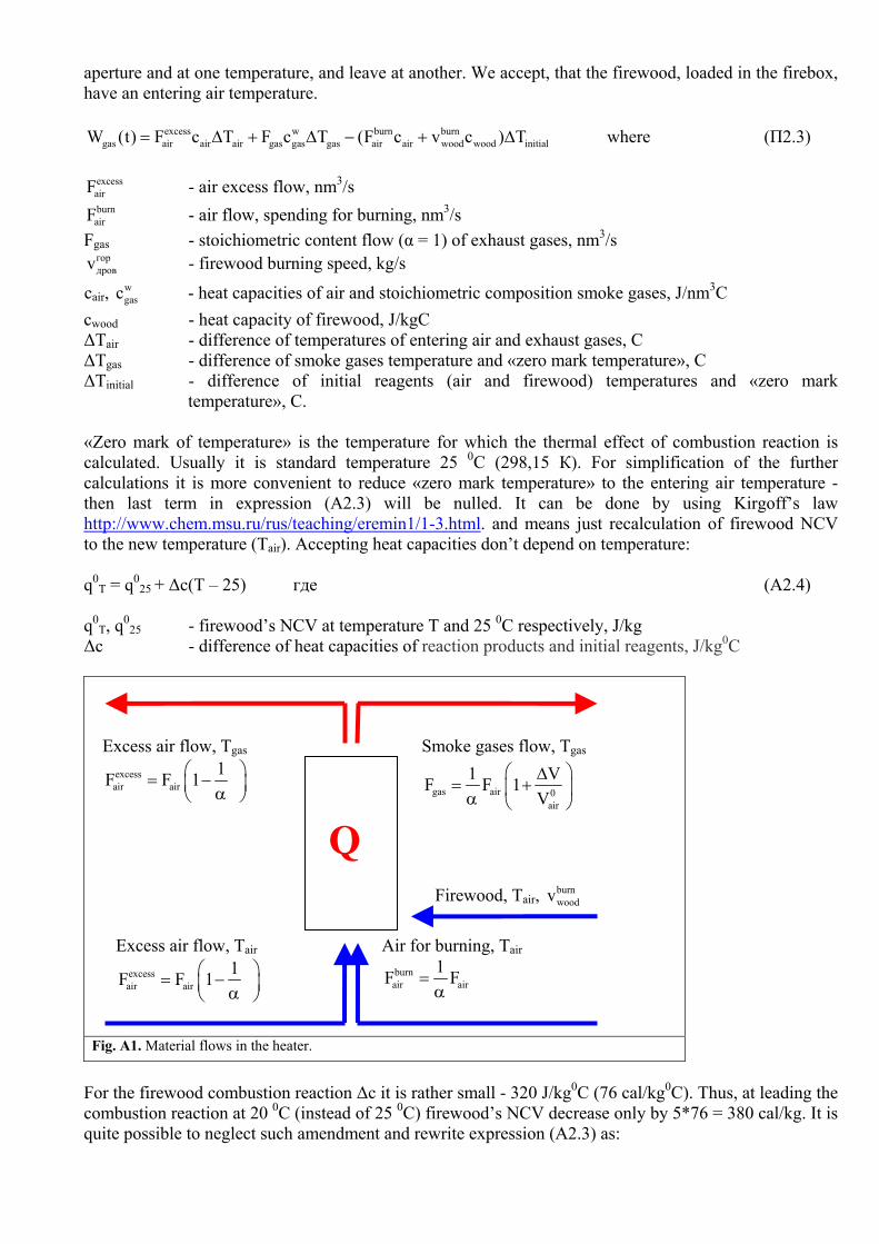
aperture and at one temperature, and leave at another. We accept, that the firewood, loaded in the firebox, have an entering air temperature.
excess w burn burngas air air air gas gas gas air air wood wood initialW (t) F c T F c T (F c v c ) T= ∆ + ∆ − + ∆ where (П2.3)
excessairF - air excess flow, nm3/s burnairF - air flow, spending for burning, nm3/s
Fgas - stoichiometric content flow (α = 1) of exhaust gases, nm3/s гордровv - firewood burning speed, kg/s
сair, wgasc - heat capacities of air and stoichiometric composition smoke gases, J/nm3C
cwood - heat capacity of firewood, J/kgC ∆Тair - difference of temperatures of entering air and exhaust gases, C ∆Тgas - difference of smoke gases temperature and «zero mark temperature», C ∆Тinitial - difference of initial reagents (air and firewood) temperatures and «zero mark
temperature», C. «Zero mark of temperature» is the temperature for which the thermal effect of combustion reaction is calculated. Usually it is standard temperature 25 0С (298,15 К). For simplification of the further calculations it is more convenient to reduce «zero mark temperature» to the entering air temperature - then last term in expression (A2.3) will be nulled. It can be done by using Kirgoff’s law http://www.chem.msu.ru/rus/teaching/eremin1/1-3.html. and means just recalculation of firewood NCV to the new temperature (Tair). Accepting heat capacities don’t depend on temperature: q0
T = q025 + ∆c(T – 25) где (A2.4)
q0
T, q025 - firewood’s NCV at temperature T and 25 0С respectively, J/kg
∆c - difference of heat capacities of reaction products and initial reagents, J/kg0C
Fig. A1. Material flows in the heater.
For the firewood combustion reaction ∆c it is rather small - 320 J/kg0C (76 cal/kg0C). Thus, at leading the combustion reaction at 20 0С (instead of 25 0C) firewood’s NCV decrease only by 5*76 = 380 cal/kg. It is quite possible to neglect such amendment and rewrite expression (A2.3) as:
Excess air flow, Тair excessair air
1F F 1 ⎛ ⎞= −⎜ ⎟α⎝ ⎠
Air for burning, Tair burnair air
1F F =α
Firewood, Tair, burnwoodv
Excess air flow, Тgas excessair air
1F F 1 ⎛ ⎞= −⎜ ⎟α⎝ ⎠
Smoke gases flow, Tgas
gas air 0air
1 VF F 1V
⎛ ⎞∆= +⎜ ⎟α ⎝ ⎠
Q

excessgas air air gas air gas gas gas airW (t) F c (T T ) F c (T T )= − + − (A2.5)
By substitution into (A2.5) values of gas flows from fig. A1 it is possible to write down:
w 0gas air
gas air air air 0air air
c V V1W (t) F с Т 1 1с V
⎡ ⎤⎛ ⎞+ ∆= ∆ + −⎢ ⎥⎜ ⎟⎜ ⎟α⎢ ⎥⎝ ⎠⎣ ⎦
where (A2.6)
Fair - total entering air flow, nm3/s V0
air - specify stoichiometric air volume for combustion of absolutely dry firewood, nm3/kg ∆V = V0
gas – V0air + w w
H2OV (A1.7) - increasing (in comparison with entered air volume) of specify volume of exhaust gases, nm3/kg
Heat power emitted by firewood’s combustion at the moment t is expressed as:
Wburn(t) = qw burnwoodv = w burn
air0air
1 wq F (t)V+
= w air0air
F (t)1 wqV (t)+
⋅α
(A2.7)
By substitution of (A2.6) and (A2.7) into (A2.2), and (A2.6) into (A2.1) we receive formulas for integral and current efficiency:
1- η = 2
1
t
air air air0t
(1 w) с Т F 1 dtM(q 620w) (t)
⎛ ⎞+ β∆ +⎜ ⎟− α⎝ ⎠
∫ (A2.8)
1- ηt = [ ]0air air air0
V с Т (t)q 620w
∆α +β
− where (A2.9)
w 0 wgas air H2O
0air air
c V wV 1с V
+β = − (A2.10)
∆Tair = Tgas – Tair w - firewood moisture, shares q0 - NCV of absolutely dry firewood, J/kg α - air excess factor сair - air heat capacity, J/nm3C сw
gas - smoke gases heat capacity, formed by stoichiometric combustion of firewood with moisture w, J/nm3C
M - firewood’s load mass, kg Tgas - smoke gas temperature, C Tair - entering air temperature, C Fair - total entering air flow, nm3/s
wH2OV - specific volume of water vapors at NTP 1,244 nm3/kg
V0air - specify stoichiometric volume of air for combustion of absolutely dry firewood, nm3/kg
If we want to take into account the heat capacity temperature dependences, in expressions (A2.8) and (A2.9) product с∆Т (and in (A2.10) heat capacities – ∆Т was canceled in β equation) it is necessary to replace with the corresponding definite integral of a heat capacity by temperature from Tair to T. Taking into account, that heat capacities in an temperature interval interesting for us are approximated by linear dependences to take this integral does not represent any complexity. An example: a thermal capacity c = a+bT, to find с∆Т:

air
Т2 2
air airT
1с Т cdT a(T T ) b(T T )2
∆ = = − + −∫ (A2.11)
European standard EN 15250 [6] at calculation total heat of gases takes into account the temperature dependence of heat capacities; about what speaks the presence of square-law terms of temperature in expressions (A.15) and (A.16). 6.3 TRANSLATION FACTORS OF THE BASIC PHYSICAL VALUES, USED IN THIS ARTICLE Work, energy, quantity of heat. 1 cal = 4,184 J
1 kWh = [ ] [ ] [ ]kJ1 3600 s 3600 kJ 860 kcals
⎡ ⎤ ⋅ = =⎢ ⎥⎣ ⎦
Power – work in time unit.
[ ][ ] [ ]4184 J / kcalkcal kcal J1 1 1,16 1,16 W
h h 3600 s / h s⎡ ⎤ ⎡ ⎤ ⎡ ⎤= ⋅ = =⎢ ⎥ ⎢ ⎥ ⎢ ⎥⎣ ⎦ ⎣ ⎦ ⎣ ⎦
Amount of matter, volume. 1 mol – amount of matter, containing 6,02·1023 molecules (Avogadro constant) 1 mol = 22,41 liters for gases at NTP – 0 0C, 1 atm. Labor equivalents. 1 USD = 29 RUR (approx)
7. SOME FACTS, FOUND OUT AFTER THIS ARTICLE WAS WRITTEN
After this article was written, and also during its discussion at Internet forums some questions causing difficulties earlier have been found out. We shall result them in this section. Probably, it’ll be continued. 7.1 NCV OF WOOD BY EUROPEAN STANDARD EN 15250 In article we notice a mistake at determination of NCV of absolutely dry wood by European standard EN15250. Here we stop at this question in detail. In European standard EN15250 on page 51 table B1 - Test fuel specifications is represented. There is column Net (lower) calorific value (as fired basis) ISO 1928:1995. It means the lowest heat of combustion of fuel. As fire basis, - as we suppose, means «on a working basis», (as it burns). For some reason, for firewood the value is not specified. Probably because used standard ISO 1928:1995 is not distributed to firewood. (we managed only ISO 1928:76, same Russian standard GOST 147 - 95). In the table only recalculation formula is given:
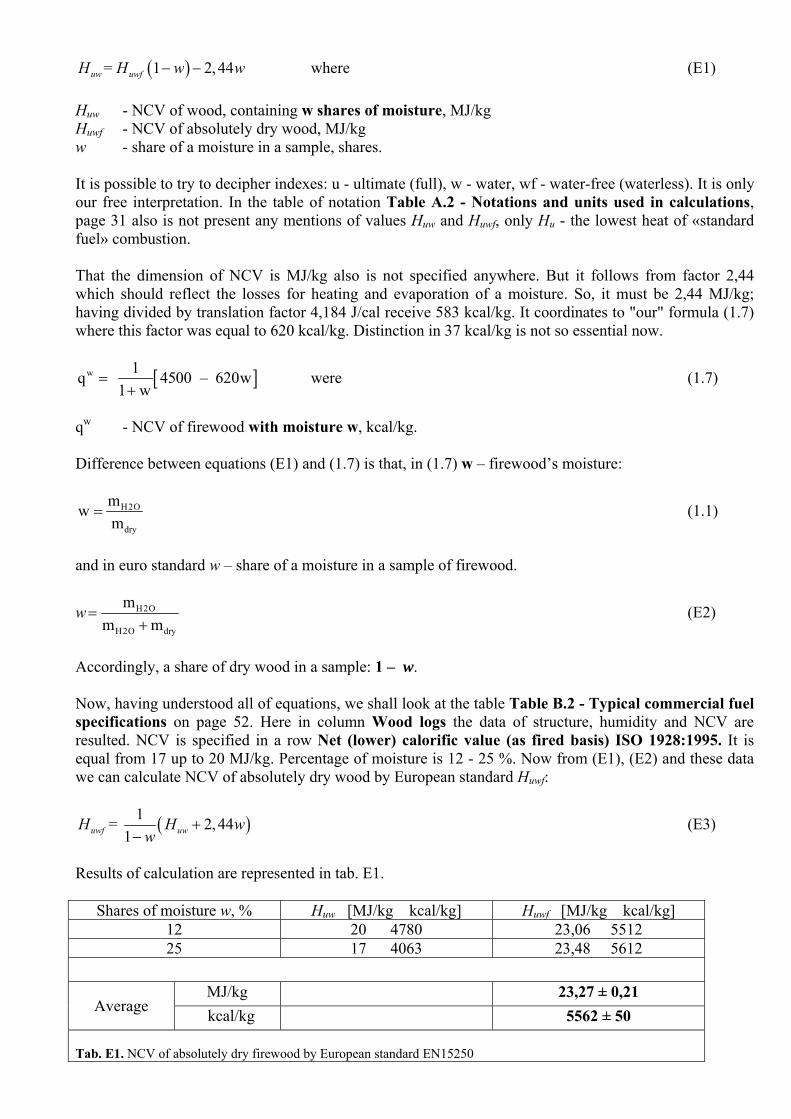
( )= 1 2, 44− −uw uwfH H w w where (E1) Нuw - NCV of wood, containing w shares of moisture, MJ/kg Huwf - NCV of absolutely dry wood, MJ/kg w - share of a moisture in a sample, shares. It is possible to try to decipher indexes: u - ultimate (full), w - water, wf - water-free (waterless). It is only our free interpretation. In the table of notation Table A.2 - Notations and units used in calculations, page 31 also is not present any mentions of values Нuw and Huwf, only Hu - the lowest heat of «standard fuel» combustion. That the dimension of NCV is MJ/kg also is not specified anywhere. But it follows from factor 2,44 which should reflect the losses for heating and evaporation of a moisture. So, it must be 2,44 MJ/kg; having divided by translation factor 4,184 J/cal receive 583 kcal/kg. It coordinates to "our" formula (1.7) where this factor was equal to 620 kcal/kg. Distinction in 37 kcal/kg is not so essential now.
[ ]w 1q 4500 – 620w1 w
=+
were (1.7)
qw - NCV of firewood with moisture w, kcal/kg. Difference between equations (E1) and (1.7) is that, in (1.7) w – firewood’s moisture:
H2O
dry
mwm
= (1.1)
and in euro standard w – share of a moisture in a sample of firewood.
w H2O
H2O dry
mm m
=+
(E2)
Accordingly, a share of dry wood in a sample: 1 – w. Now, having understood all of equations, we shall look at the table Table B.2 - Typical commercial fuel specifications on page 52. Here in column Wood logs the data of structure, humidity and NCV are resulted. NCV is specified in a row Net (lower) calorific value (as fired basis) ISO 1928:1995. It is equal from 17 up to 20 MJ/kg. Percentage of moisture is 12 - 25 %. Now from (E1), (E2) and these data we can calculate NCV of absolutely dry wood by European standard Huwf:
( )1= 2,441
+−uwf uwH H w
w (E3)
Results of calculation are represented in tab. Е1.
Shares of moisture w, % Нuw [MJ/kg kcal/kg] Huwf [MJ/kg kcal/kg] 12 20 4780 23,06 5512 25 17 4063 23,48 5612
MJ/kg 23,27 ± 0,21
Average kcal/kg 5562 ± 50 Tab. Е1. NCV of absolutely dry firewood by European standard EN15250

CONCLUSION
Thus, NCV of absolutely dry wood by European standard EN15250 is equal to 5562 kcal/kg. In the Russian literature values are about 4500 kcal/kg. The question demands more serious consideration. In article we have specified the value of 5338 kcal/kg, by mistake not having noticed the distinction between moisture and shares of moisture in a sample. 7.2 MAXIMAL CONCENTRATION OF CO2 IN EXHAUST GASES AND ACCURACY OF AIR EXCESS FACTOR DETERMINATION By discussion of article it has been found out, that maximal concentration СО2 in the smoke gases, specified gas-analyzer’s manufacturers, is concentration in the drained smoke gases. Also it has been found out, that a gas-analyzer before direction gases onto concentration electrochemical sensors of oxygen and carbon monoxide condenses moisture of smoke gases. This procedure is necessary because of two reasons – at first, water vapors condensation at the sensors surface will reduce their lifetime, and secondary it allows don’t take into account fuel’s moisture at calculation of air excess factor. Really, if the analyzer would measure concentration of oxygen in damp gases, evaporated water contained in fuel, would dilute gases, and determination of air excess factor (α) only by oxygen concentration would not be possible. But in this case there is an inaccuracy in calculation of α by concentration of oxygen in smoke gases for hydrogen-contain fuels. We consider it more in detail by the example of combustion of pure hydrogen in air. H2 + 0,5 1/0,21 (0,21 O2 + 0,79 N2) = H2O↓ + 0,5 0,79/0,21 N2 (C1) Air excess factor can be calculated from oxygen concentration by formula:
[ ]2
2121 O
α =−
(C2)
From the equations (C1) and (C2) it is easy to estimate the influence of water vapors absence in smoke gases to a value of air excess factor, calculated trough oxygen concentration:
calc real1, 27 0,27α = α − (C3) At fig. С1 this dependence is represented graphically and fig. С2 illustrates the value of error:
calc real
real
Err 100%α −α=
α.
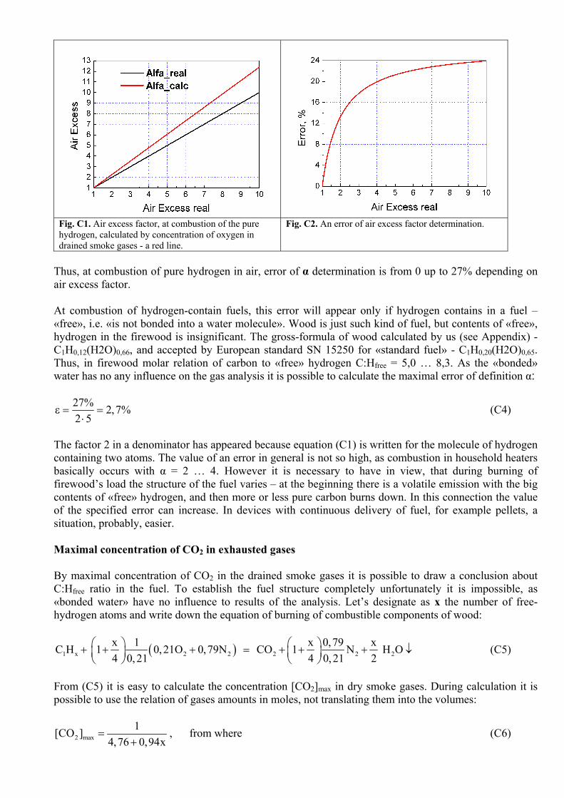
Fig. С1. Air excess factor, at combustion of the pure hydrogen, calculated by concentration of oxygen in drained smoke gases - a red line.
Fig. С2. An error of air excess factor determination.
Thus, at combustion of pure hydrogen in air, error of α determination is from 0 up to 27% depending on air excess factor. At combustion of hydrogen-contain fuels, this error will appear only if hydrogen contains in a fuel – «free», i.e. «is not bonded into a water molecule». Wood is just such kind of fuel, but contents of «free», hydrogen in the firewood is insignificant. The gross-formula of wood calculated by us (see Appendix) - С1Н0,12(Н2О)0,66, and accepted by European standard SN 15250 for «standard fuel» - С1Н0,20(Н2О)0,65. Thus, in firewood molar relation of carbon to «free» hydrogen С:Hfree = 5,0 … 8,3. As the «bonded» water has no any influence on the gas analysis it is possible to calculate the maximal error of definition α:
27% 2,7%2 5
ε = =⋅
(C4)
The factor 2 in a denominator has appeared because equation (С1) is written for the molecule of hydrogen containing two atoms. The value of an error in general is not so high, as combustion in household heaters basically occurs with α = 2 … 4. However it is necessary to have in view, that during burning of firewood’s load the structure of the fuel varies – at the beginning there is a volatile emission with the big contents of «free» hydrogen, and then more or less pure carbon burns down. In this connection the value of the specified error can increase. In devices with continuous delivery of fuel, for example pellets, a situation, probably, easier. Maximal concentration of CO2 in exhausted gases By maximal concentration of СО2 in the drained smoke gases it is possible to draw a conclusion about С:Hfree ratio in the fuel. To establish the fuel structure completely unfortunately it is impossible, as «bonded water» have no influence to results of the analysis. Let’s designate as x the number of free-hydrogen atoms and write down the equation of burning of combustible components of wood:
( )1 х 2 2 2 2 2x 1 x 0,79 xС Н 1 0,21O 0,79N CO 1 N H O4 0,21 4 0,21 2
⎛ ⎞ ⎛ ⎞+ + + = + + + ↓⎜ ⎟ ⎜ ⎟⎝ ⎠ ⎝ ⎠
(C5)
From (С5) it is easy to calculate the concentration [CO2]max in dry smoke gases. During calculation it is possible to use the relation of gases amounts in moles, not translating them into the volumes:
2 max1[CO ]
4,76 0,94x=
+, from where (C6)
2 max
1x 1,06 4,76 [CO ]
⎛ ⎞= −⎜ ⎟
⎝ ⎠ (C7)
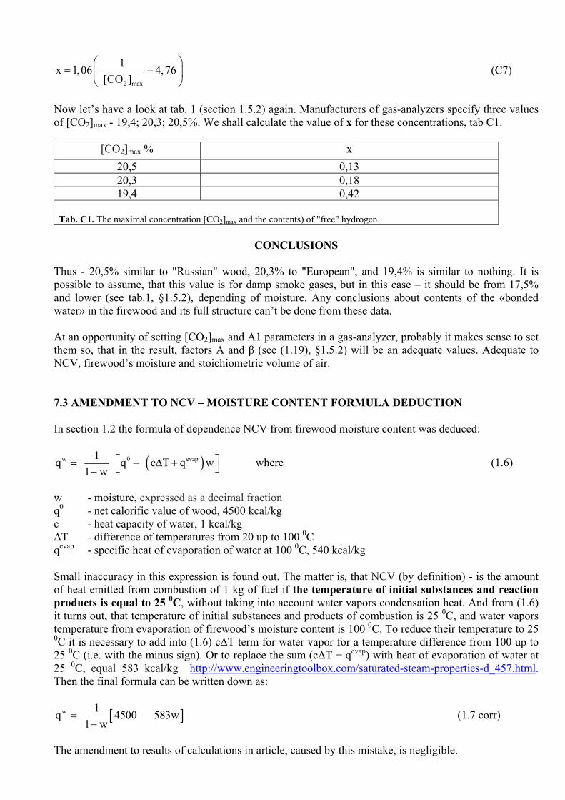
Now let’s have a look at tab. 1 (section 1.5.2) again. Manufacturers of gas-analyzers specify three values of [CO2]max - 19,4; 20,3; 20,5%. We shall calculate the value of x for these concentrations, tab C1.
[CO2]max % x 20,5 0,13 20,3 0,18 19,4 0,42
Tab. С1. The maximal concentration [CO2]max and the contents) of "free" hydrogen.
CONCLUSIONS
Thus - 20,5% similar to "Russian" wood, 20,3% to "European", and 19,4% is similar to nothing. It is possible to assume, that this value is for damp smoke gases, but in this case – it should be from 17,5% and lower (see tab.1, §1.5.2), depending of moisture. Any conclusions about contents of the «bonded water» in the firewood and its full structure can’t be done from these data. At an opportunity of setting [CO2]max and А1 parameters in a gas-analyzer, probably it makes sense to set them so, that in the result, factors A and β (see (1.19), §1.5.2) will be an adequate values. Adequate to NCV, firewood’s moisture and stoichiometric volume of air. 7.3 AMENDMENT TO NCV – MOISTURE CONTENT FORMULA DEDUCTION In section 1.2 the formula of dependence NCV from firewood moisture content was deduced:
( )w 0 evap1q q – c T q w1 w
⎡ ⎤= ∆ +⎣ ⎦+ where (1.6)
w - moisture, expressed as a decimal fraction q0 - net calorific value of wood, 4500 kcal/kg с - heat capacity of water, 1 kcal/kg ∆T - difference of temperatures from 20 up to 100 0С qevap - specific heat of evaporation of water at 100 0С, 540 kcal/kg Small inaccuracy in this expression is found out. The matter is, that NCV (by definition) - is the amount of heat emitted from combustion of 1 kg of fuel if the temperature of initial substances and reaction products is equal to 25 0С, without taking into account water vapors condensation heat. And from (1.6) it turns out, that temperature of initial substances and products of combustion is 25 0С, and water vapors temperature from evaporation of firewood’s moisture content is 100 0С. To reduce their temperature to 25 0С it is necessary to add into (1.6) с∆T term for water vapor for a temperature difference from 100 up to 25 0С (i.e. with the minus sign). Or to replace the sum (с∆T + qevap) with heat of evaporation of water at 25 0С, equal 583 kcal/kg http://www.engineeringtoolbox.com/saturated-steam-properties-d_457.html. Then the final formula can be written down as:
[ ]w 1q 4500 – 583w1 w
=+
(1.7 corr)
The amendment to results of calculations in article, caused by this mistake, is negligible.