hcl industrial training report
DESCRIPTION
THIS PROJECT BASED ON JAVA PROGRAMMINGTRANSCRIPT
A
Training Report on
“OFC, Signal Engineering & Data Communication”
Submitted in partial fulfillment of the requirement for the award of Degree of
Bachelor of Engineering in Electronics & Communication
Submitted to
RAJIV GANDHI PROUDYOGIKI VISHWAVIDHYALAYA, BHOPAL (M.P.)
Submitted by
Shivam Pandey
(0114EC111095)
Under the Supervision of
Mr. Neelesh Gupta
(Head Of Department)
DEPARTMENT OF ELECTRONICS & COMMUNICATION ENGINEERING
TRUBA INSTITUTE OF ENGINEERING & INFORMATION
TECHNOLOGY BHOPAL
Karond,Gandhi nagar,Bhopal

MAJOR TRAINING
ABOUT MARUCOM
Marucom, one of the world’s leading Telecom service providers, They are known for their
innovative approach and world-class technology. It’s aim is to provide you superior products
and services, anytime and anywhere.
Marucom is leading in delivering best telecom solution , committed to innovation and
technology with businesses spanning the globe. Its working on an array of telecom services
deals and established as a trademark in making telecom business. Company is owned by
qualified Telecom professionals.
Focus is more on the latest telecom technologies like 3G. We are already executing 3G and
Wimax projects in India and have initiated team built up for LTE and 4G services.
They have a separate telecom technology Excellence(TTE) group works on part of grooming
Marucom with latest telecom Trends and new efficient tools to reduce the man hours and
increase the quality of output. It’s a pure Research group having a team of experienced R&D
professionals.
Marucom is known for having high quality processes and standards to maintain predictable,
consistent and defect free delivery to their valuable customer.
Marucom Group has four core businesses:
• Telecom
• Power
• Engineering Construction
• Education
TRUBA INSTITUTE OF ENGINEERING & INFORMATION TECHNOLOGY Page 2

MAJOR TRAINING
TRUBA INSTITUTE OF ENGINEERING & INFORMATION TECHNOLOGY Page 3

MAJOR TRAINING
ABOUT HCL:
HCL INFO-SYSTEM Ltd. is a leading IT company with over 10 years of leadership in
Website design, Software development & Internet Marketing. HCL INFO-SYSTEM Ltd.
provides a unique approach software engineering & follows well defined process based
workflows to develop value added yet cost effective courses that fulfill your learning
objectives. Whether you wish to increase awareness or competency in the IT world HCL
INFO-SYSTEM Ltd. is the right choice.
HCL INFO-SYSTEM Ltd. is India's pioneer in Internet and eCommerce and offers
integrated end-to-end solutions for both the Business to Consumer (B2C) and Business to
Business (B2B) segments, which cover the four critical corner stones of the Net:
Connectivity, Content, Commerce and Community. HCL INFO-SYSTEM Ltd. cutting edge
B2B services including connectivity solutions like Electronic Data Interface, Virtual Private
Networks, Security Services, Network Management Services as well as eSolutions services
that include Internet Consulting, Solutions Architectures, Design and Development of
Solutions, Hosting and Management Services and eCommerce products, are relied upon by
leading Corporate in India.
TRUBA INSTITUTE OF ENGINEERING & INFORMATION TECHNOLOGY Page 4
MAJOR TRAINING
CONTENTS
Introduction to cellular Mobile Technologies
Digital cellular Technologies
GSM System Hierarchy
GSM Architecture
Function of MS,BTS,BSC & MSC
GSM Cellular technologies
Handoff Mechanism
Different sizes of microwave antenna used
RF planning and optimization
Comparison between Microwave and Fiber lines
Different cards and their functions
Drive test
RF SURVEY
Types of tower
Transmission Planning
Operation and Maintenance
2.5 G,3G,4G & Wi-max technologies
GSM Protocols
Networking Basics
The OSI Reference Model
The TCP/IP Protocol Stack
IP addressing and subnetting
Resource Sharing and Remote Access Services
Routing Basics
Introduction to the Cisco Router
Cisco Router Basic Commands
Implementing static routing
TRUBA INSTITUTE OF ENGINEERING & INFORMATION TECHNOLOGY Page 5
MAJOR TRAINING
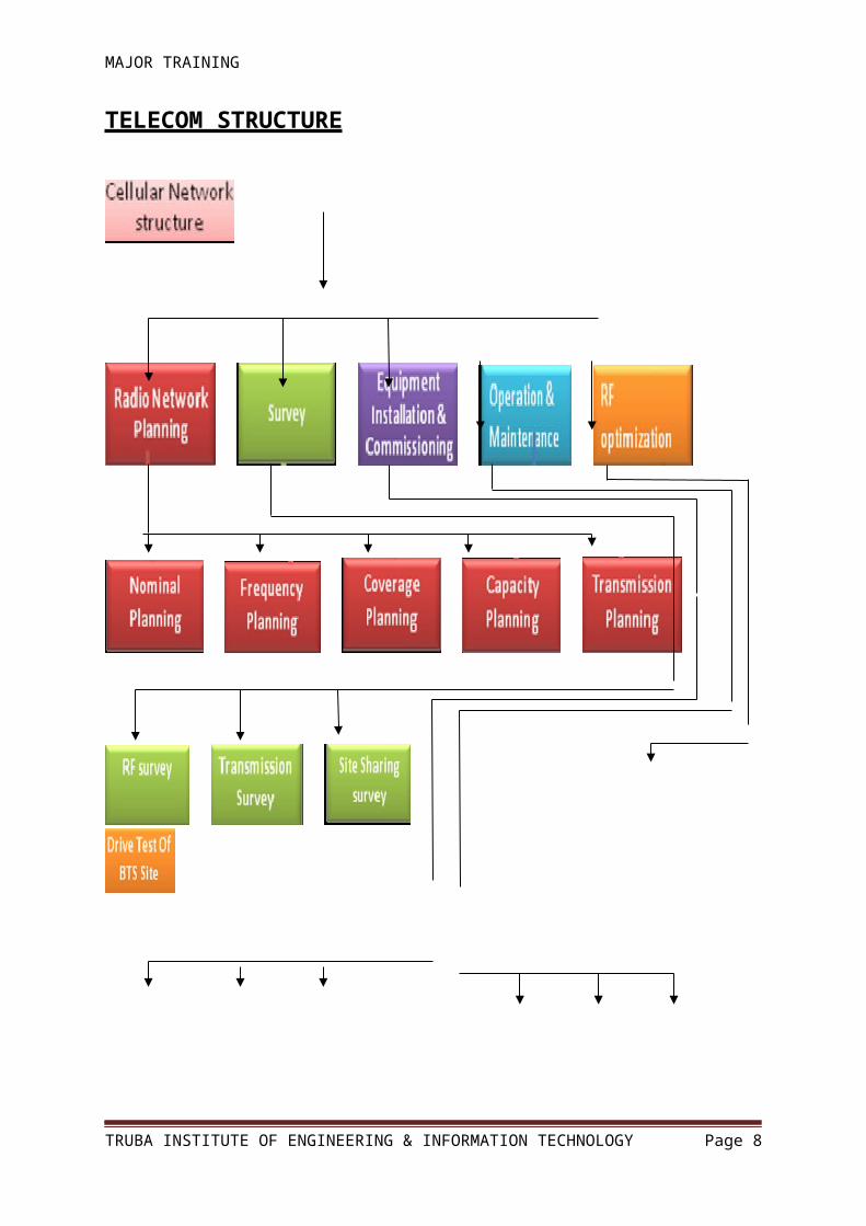
TELECOM STRUCTURE
Digital Cellular Technologies
TRUBA INSTITUTE OF ENGINEERING & INFORMATION TECHNOLOGY Page 6
MAJOR TRAINING
FDMA
Frequency Division Multiple Access (FDMA) is a multiple access technology used in the
analog cellular telephone network that divides the spectrum into 30kHz channels using
Frequency Division Multiplexing (FDM). FDMA is used by the Total Access
Communication System (TACS) and Advanced Mobile Phone System (AMPS) analog
cellular systems. Another example of FDMA is AM or FM radio broadcasting, where each
station has its own channel.
TDMA
Time division Multiple Access (TDMA ) works by dividing a radio frequency into time slots
and then allocating slots to multiple calls. In this way, a single frequency can support
multiple, simultaneous data channels. TDMA is used by
the GSM digital cellular system.
CDMA
TRUBA INSTITUTE OF ENGINEERING & INFORMATION TECHNOLOGY Page 7
MAJOR TRAINING
Code Division Multiple Access (CDMA) is an advanced multiple access technique. In
CDMA, all users use the same frequency at the same time. The signals are divided using the
orthogonality or quasi-orthogonality of the access code waveforms for different users and
channel is a unique code pattern .
GSM System Hierarchy
Macrocell
Provides the largest area of coverage within a mobile network. Its antennas can be mounted
on ground-based masts, rooftops or other structures and must be high enough to avoid
obstruction. Macrocells provide radio coverage over varying distances, depending on the
frequency used, the number of calls and the physical terrain.
Microcells
Provide additional coverage and capacity in areas where there are high numbers of users,
urban and suburban areas, for example. The antennas for microcells are mounted at street
level, are smaller than macrocell antennas and can often be disguised as building features so
that they are less visually intrusive.Microcells provide radio coverage over distances –
typically between 300m and 1000m – and have lower output powers than macrocells, usually
a few watts.
Picocells
TRUBA INSTITUTE OF ENGINEERING & INFORMATION TECHNOLOGY Page 8

MAJOR TRAINING
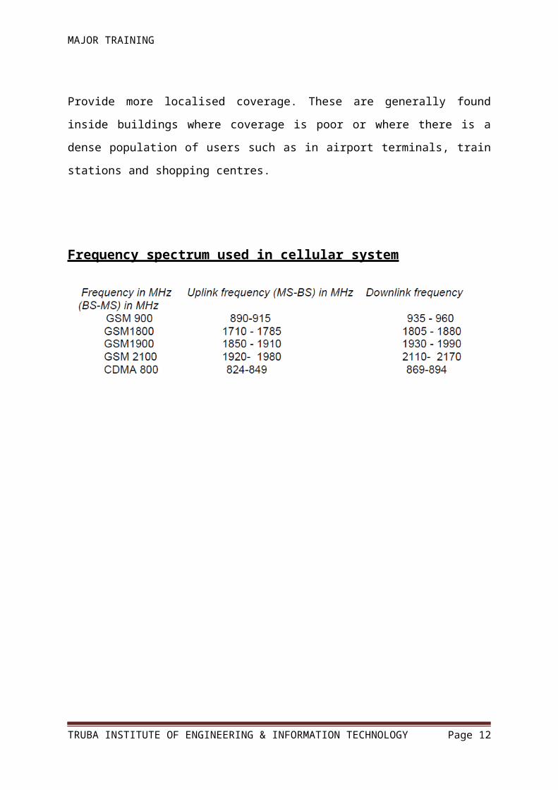
Provide more localised coverage. These are generally found inside buildings where coverage
is poor or where there is a dense population of users such as in airport terminals, train stations
and shopping centres.
Frequency spectrum used in cellular system
TRUBA INSTITUTE OF ENGINEERING & INFORMATION TECHNOLOGY Page 9

MAJOR TRAINING
GSM Network Architecture
Function of MSThe primary functions of MS are to transmit and receive voice and data over the air interface
of the GSM system. MS performs the signal processing function of digitizing, encoding, error
protecting, encrypting, and modulating the transmitted signals. It also performs the inverse
functions on the received signals from the BS.
TRUBA INSTITUTE OF ENGINEERING & INFORMATION TECHNOLOGY Page 10

MAJOR TRAINING
Function of BTS
The BTS handles the radio interface to the mobile station. The BTS is the radio equipment
(transceivers and antennas) needed to service each cell in the network. A group of BTSs are
controlled by a BSC. The primary responsibility of the BTS is to transmit and receive radio
signals from a mobile unit over an air interface. To perform this function completely, the
signals are encoded,encrypted, multiplexed, modulated, and then fed to the antenna system at
the cell site.
Function of BSC
It is a functional entity that handles common control functions within a BTS. BSC within a
mobile network is a key component for handling and routing information. The BSC provides
all the control functions and physical links between the MSC and BTS. It is a high-capacity
switch that provides functions such as handover, cell configuration data, and control of
radiofrequency (RF) power levels in base transceiver stations. A number of BSCsare served
by an MSC.
The BSC is connected to the MSC on one side and to the BTS on the other. The BSC
performs the Radio Resource (RR) management for the cells under its control. It assigns and
releases frequencies and timeslots for all MSs in its own area. The BSC performs the intercell
handover for MSs moving between BTS in its control. It also reallocates frequencies to the
BTSs in its area to meet locally heavy demands during peak hours or on special events. The
BSC controls the power transmission of both BSSs and MSs in its area.
The minimum power level for a mobile unit is broadcast over the BCCH. The BSC provides
the time and frequency synchronization reference signals broadcast by its BTSs. The BSC
also measures the time delay of received MS signals relative to the BTS clock. If the received
MS signal is not centered in its assigned timeslot at the BTS, The BSC can direct the BTS to
notify the MS to advance the timing such that proper synchronization takes place.
TRUBA INSTITUTE OF ENGINEERING & INFORMATION TECHNOLOGY Page 11
MAJOR TRAINING
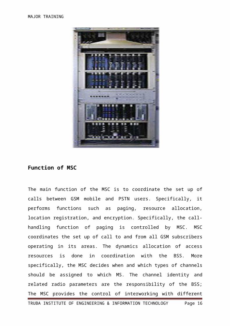
Function of MSC
The main function of the MSC is to coordinate the set up of calls between GSM mobile and
PSTN users. Specifically, it performs functions such as paging, resource allocation, location
registration, and encryption. Specifically, the call-handling function of paging is controlled
by MSC. MSC coordinates the set up of call to and from all GSM subscribers operating in its
areas. The dynamics allocation of access resources is done in coordination with the BSS.
More specifically, the MSC decides when and which types of channels should be assigned to
which MS. The channel identity and related radio parameters are the responsibility of the
BSS; The MSC provides the control of interworking with different networks. It is transparent
for the subscriber authentication procedure. The MSC supervises the connection transfer
between different BSSs for MSs, with an active call, moving from one call to another. This is
ensured if the two BSSs are connected to the same MSC but also when they are not. In this
latter case the procedure is more complex, since more then one MSC involved. The MSC
performs billing on calls for all subscribers based in its areas.
TRUBA INSTITUTE OF ENGINEERING & INFORMATION TECHNOLOGY Page 12

MAJOR TRAINING
When the subscriber is roaming elsewhere, the MSC obtains data for the call billing from the
visited MSC. Encryption parameters transfers from VLR to BSS to facilitate ciphering on the
radio interface are done by MSC. The exchange of signaling information on the various
interface toward the other network elements and the management of the interface themselves
are all controlled by the MSC
.
TRUBA INSTITUTE OF ENGINEERING & INFORMATION TECHNOLOGY Page 13

MAJOR TRAINING
GSM Cellular Technologies1. GPRS (2.5 G)- General Packet radio service supports data calls up to 115 Kbps
TRUBA INSTITUTE OF ENGINEERING & INFORMATION TECHNOLOGY Page 14
MAJOR TRAINING
2. EDGE (2.75 G)- Enhanced data rates for GSM evolution, data up to 384 Kbps
Temporary solution for operators, unable to get W-CDMA licenses, offers higher speed
Mobile data access.
3. W-CDMA (3G)- Support of high data rate transmission,384 Kbps with wide area coverage
& 2 Mbps with local area coverage.
4. LTE (4G)- 4G is a multi purpose and versatile technology hence it can utilize almost all of
the packet switched technologies. It uses orthogonal frequency division multiplexing
(OFDM).
Wi-Max Technology
Wi-Max stands for ”World wide interoperability for Microwave Access”. Wi-max is based
Up on the IEEE 802.16 standard. In fact, wi-max is not a technology, it is a certification
mark. IEEE 802.16 has designed the Interoperability test. Wi-Max has two applications one
for fixed wi-max and other is Mobile wimax. Orthogonal frequency division multiplexing
(OFDM) is used in wi-max to achieve high speed bi-directional wireless data communication.
Microwave LinkStrength1. Adapts to difficult terrain
2. Flexible channelization
3. Relatively short installation time
4. Can be transportable
5. Cost usually less than cable
Weakness1. Paths could be blocked by buildings
2. Spectral congestion
3. Interception possible
4. Possible regulatory delays
5. Sites could be difficult to maintain
Handoff Mechanism
TRUBA INSTITUTE OF ENGINEERING & INFORMATION TECHNOLOGY Page 15
MAJOR TRAINING
Handoff is the switching of an ongoing call to a different channel or cell. There are four
different types of handover in the GSM system, which involve transferring a call between-
1. Channels (time slots) in the same cell
2. Cells (Base Transceiver Stations) under the control of the same Base Station Controller
3. Cells under the control of different BSCs, but belonging to the same Mobile services
Switching Center (MSC), and
4. Cells under the control of different MSCs.
Hard HandoffWhen mobile (in Call) switches to a new sector/Cell which is on different frequency , then it
performs hard Handoff. It is basically an inter-frequency handoff. It is also called break-
before make.
Soft HandoffWhen mobile ( in Call) switches to a new sector/cell which is on the same frequency then it is
called a soft handoff. If the "new" sector is also from the same BTS then it is called a softer
handoff. It is also called make-before break.
Channel Properties of CDMAThe forward channel (from base station to mobile) is made up of the following
channels:
Pilot channel (always uses Walsh code W0) (Beacon Signals)
Paging channel(s) (use Walsh codes W1-W7)
Sync channel (always uses Walsh code W32)
Traffic channels (use Walsh codes W8-W31 and W33-W63)
The reverse channel (from mobile to base station) is made up of the following
channels:
TRUBA INSTITUTE OF ENGINEERING & INFORMATION TECHNOLOGY Page 16

MAJOR TRAINING
Access channel
Traffic channel
Different sizes of Microwave Antenna used in communication
Link (LOS)-8. 0.3 M (Diameter)
9. 0.6 M (Diameter)
10. 1.2 M (Diameter)
11. 1.8 M (Diameter)
12. 2.4 M (Diameter)
13. 3.2 M (Diameter
RF Planning
TRUBA INSTITUTE OF ENGINEERING & INFORMATION TECHNOLOGY Page 17

MAJOR TRAINING
Network Dimensioning (ND) is usually the first task to start the planning of a given cellular
network. The main result is an estimation of the equipment necessary to meet the following
requirements.
Network dimensioning input The inputs are
Capacity related Spectrum available.
Subscriber growth forecast
Coverage related Coverage regions
Area types information
Quality related MS classes
Blocking probability
Location probability
Indoor coverage. The operator normally supplies the input data, but use of defaults is also possible. The
technical parameter and characteristics of the equipment to be used are another very
important part of the input. This includes the basic network modules (MSC, BSC, BTS)
as well as some additional elements (antennas, cables…)
RF OptimizationRF Optimization is carried out in the network to
1. Minimize the call drop and RF Interference in the network.
2. Increase the Indoor & Outdoor coverage & better speech quality.
TRUBA INSTITUTE OF ENGINEERING & INFORMATION TECHNOLOGY Page 18

MAJOR TRAINING
Different cards & their function1. Power card- Used for supply the power to different cards in BTS
2. BB2F- Used for complete digital signal processing of voice and data in BTS
3. BOI- Used for BTS Initialization, O&M function ,BTS Login & clock function4. RRI- Used for Transmission link for BTS
5. TRX- Used for allocating time slots to the user Transmitting/Receiving
6. Multi-coupler- Used for splitting of Received RF signal and distributing them to TRX
7. Duplexer- Used for combining Transmitting/Receiving RF signals in one Antenna
8. Combiner- Used to divert overload calls to one TRX to another TRX
TRUBA INSTITUTE OF ENGINEERING & INFORMATION TECHNOLOGY Page 19

MAJOR TRAINING
Drive Test-
Drive test is conducted for checking coverage criteria of a cell site with RF Drive test tool.
The data collected by drive test tool as log files as analyzed to evaluate various RF
parameters of the network.
RF Optimization equipments1. Laptop - In RF optimization, RF engineer analysis all parameters during drive test and
Install all the software on the Laptop system.
2. TEMS- This TEMS Investigation software supported cellular mobile specially design to
Perform RF optimization related activity and it is connected with laptop system And then it is
operated from the Laptop for analysis of optimized data.
3. GPS device- The GPS device also connected with the Laptop system with Mapinfo
Software support. It is used for its basic operation to locate the position.
TRUBA INSTITUTE OF ENGINEERING & INFORMATION TECHNOLOGY Page 20

MAJOR TRAINING
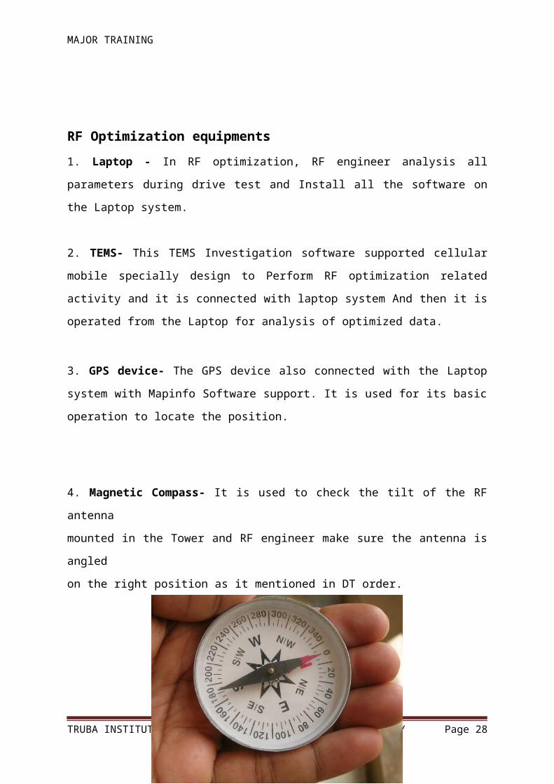
4. Magnetic Compass- It is used to check the tilt of the RF antenna
mounted in the Tower and RF engineer make sure the antenna is angled
on the right position as it mentioned in DT order.
MAGNETIC COMPASS
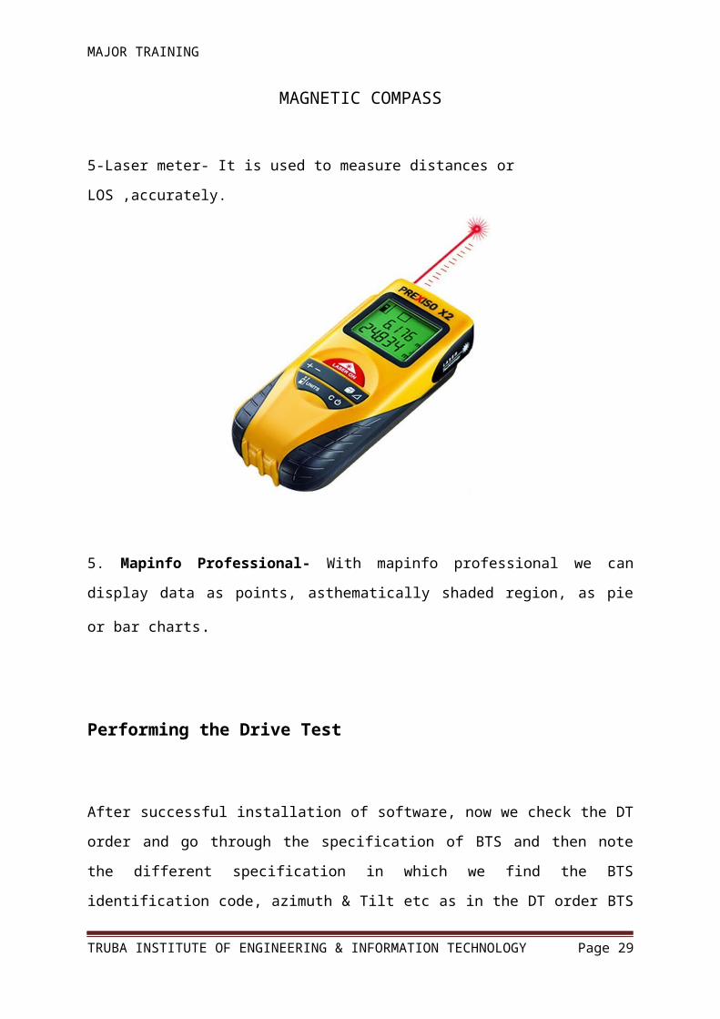
5-Laser meter- It is used to measure distances or LOS ,accurately.
TRUBA INSTITUTE OF ENGINEERING & INFORMATION TECHNOLOGY Page 21
MAJOR TRAINING
5. Mapinfo Professional- With mapinfo professional we can display data as points,
asthematically shaded region, as pie or bar charts.
Performing the Drive Test
After successful installation of software, now we check the DT order and go through the
specification of BTS and then note the different specification in which we find the BTS
identification code, azimuth & Tilt etc as in the DT order BTS location identity is define we
note that BTS ID and then we locating the BTS premises by using the mapinfo software and
reach on that location.
INTRA DT
In Intra RF engineer perform Drive test to check the handoff of Intra cell in Which RF
engineer observe the soft & Hard handoff between cells BTS. He takes drive clockwise &
counter clockwise of the BTS.
INTER DT
In Inter RF engineer perform Drive test to check the handoff between Neighbouring BTS. He
observe the soft & Hard handoff in idle & dedicate mode between Defined neighbours and
also check the Rx level, call establishing, call drop and coverage of the BTS.
RF Survey
It is collection of database from the field (according to the customer planned region that is
nominal point/Reference the area) for checking the feasibility of cell site, for decide coverage
region of cell site & for Link connectivity/LOS with another cell site.
TRUBA INSTITUTE OF ENGINEERING & INFORMATION TECHNOLOGY Page 22

MAJOR TRAINING
LOS SurveyIt is a path study between new site point to the existing site point for deciding the Microwave
antenna height that is for Fresnel zone clearance.
Nominal PointThis is a reference point given by customer for RF survey work.This may be
in any of the following form-
1. Latitude & Longitude value
2. X and Y co-ordinate
3. North/East co-ordinate
4. Area Name
Tools Required for RF survey work1. GPS- It stands for Global positioning system.
Magnetic compass- It is used for checking antenna direction.
Binocular with high visual range.
Digital camera
Measuring tape
Laptop
Software Tools Required
1. Mapinfo Professional ( Version 6.5,7,8,8.5,9)
2. Path Loss ( Version 3.0 & 4.0)
3. Global Mapper (7,8,9 & 10)
4. Google earth
Types of Tower1. GBT(Ground Base Tower)
2. RTT(Roof Top Tower)
3. RTP(Roof Top Pole)
TRUBA INSTITUTE OF ENGINEERING & INFORMATION TECHNOLOGY Page 23

MAJOR TRAINING
Transmission PlanningTransmission Planning Module deals with the building of the Transmission aspects of the
Network by the creation of physical links between Sites and logical circuits across the
Network.
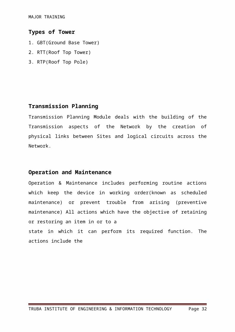
Operation and MaintenanceOperation & Maintenance includes performing routine actions which keep the device in
working order(known as scheduled maintenance) or prevent trouble from arising (preventive
maintenance) All actions which have the objective of retaining or restoring an item in or to a
state in which it can perform its required function. The actions include the
TRUBA INSTITUTE OF ENGINEERING & INFORMATION TECHNOLOGY Page 24

MAJOR TRAINING
Generations:
1G
Analog mobile System
Small size of Users
Voice Only
Expensive
Big size of devices
Standards:- AMPS, TACS, NMT
2G-2.5G
Digital System
Big size of users
Voice and Data Only
Enable internet access
Moderate data rate
Standards:- GSM(TDMA,FDMA based),CDMA
3G
Voice Data and Multimedia content
Faster Data Rate
Video telephony
Standards:- WCDMA,HSDPA (GSM based)
CDMA2000 (CDMA based)
4G
Two 4G candidates systems are commercially
deployed:-
Wi Max
LTE
TRUBA INSTITUTE OF ENGINEERING & INFORMATION TECHNOLOGY Page 25

MAJOR TRAINING
Wi Max:-
Worldwide Interoperability for Microwave Access is a wireless communications
standard.
It designed to provide 30 to 40 megabit-per-second data rates.
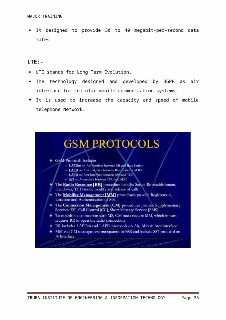
LTE:- LTE stands for Long Term Evolution.
The technology designed and developed by 3GPP as air interface for cellular mobile
communication systems.
It is used to increase the capacity and speed of mobile telephone Network.
TRUBA INSTITUTE OF ENGINEERING & INFORMATION TECHNOLOGY Page 26

MAJOR TRAINING
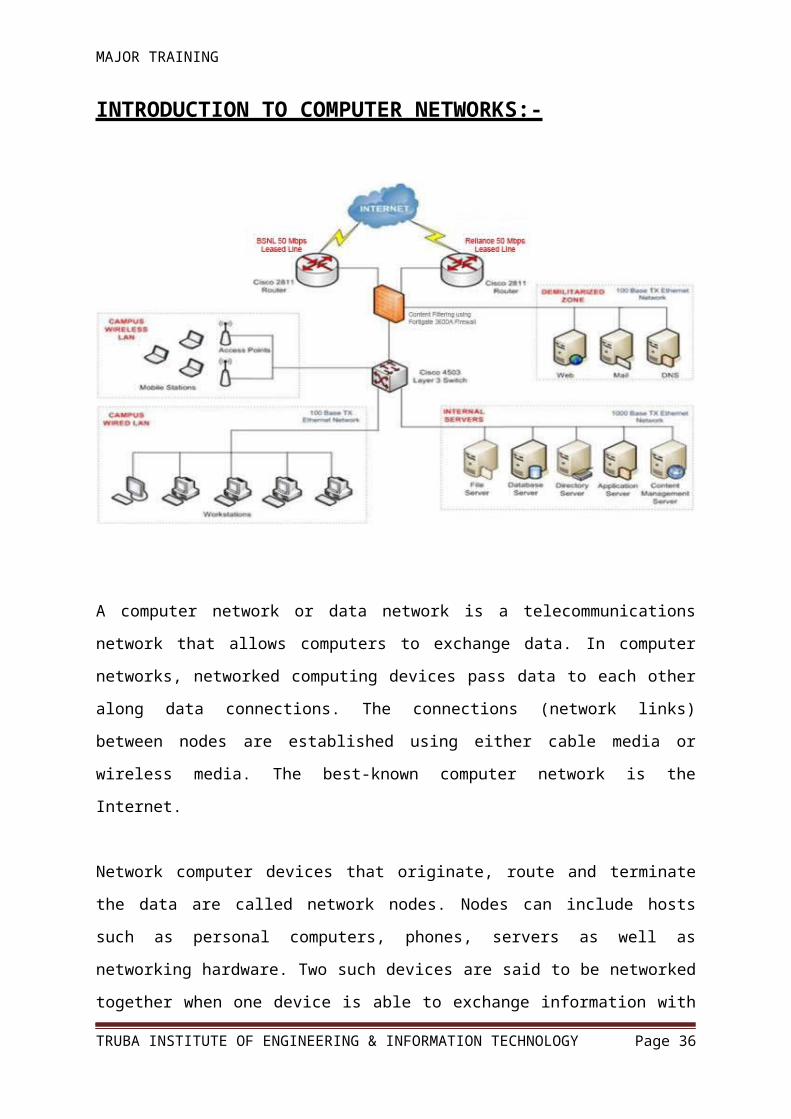
INTRODUCTION TO COMPUTER NETWORKS:-
A computer network or data network is a telecommunications network that allows computers
to exchange data. In computer networks, networked computing devices pass data to each
other along data connections. The connections (network links) between nodes are established
using either cable media or wireless media. The best-known computer network is the Internet.
Network computer devices that originate, route and terminate the data are called network
nodes. Nodes can include hosts such as personal computers, phones, servers as well as
networking hardware. Two such devices are said to be networked together when one device
is able to exchange information with the other device, whether or not they have a direct
connection to each other.
Computer networks support applications such as access to the World Wide Web, shared use
of application and storage servers, printers, and fax machines, and use of email and instant
messaging applications. Computer networks differ in the physical media used to transmit
TRUBA INSTITUTE OF ENGINEERING & INFORMATION TECHNOLOGY Page 27
MAJOR TRAINING
their signals, the communications protocols to organize network traffic, the network's size,
topology and organizational intent.
By themselves, computers are powerful tools. When they are connected in a network, they
become even more powerful because the functions and tools that each computer provides can
be shared with other computers.
Networks exist to provide logical and physical connectivity for two major reasons:
To provide information and resource sharing services. (Ex: FTP, HTTP, etc.)
To provide remote access services (Ex: TELNET, SSH, etc.)
These services are provided using server architecture technologies. Network technologies
such as LAN/WAN implementation and the TCP/IP protocol stack including the Routing
protocols are then employed to provide the means of connectivity within the different and
resources and nodes.
These networks are primarily distinguished using the network topologies being used, such as:
A. Star Topology
B. Bus Topology
C. Ring Topology
D. Mesh Topology
E. Hybrid Topology
Networks can also be classified based on areal span, such as:-
A. LAN (Local Area Network)
B. CAN (Campus Area Network)
C. MAN (Metropolitan Are Network)
D. WAN (Wide Area Network)
TRUBA INSTITUTE OF ENGINEERING & INFORMATION TECHNOLOGY Page 28
MAJOR TRAINING
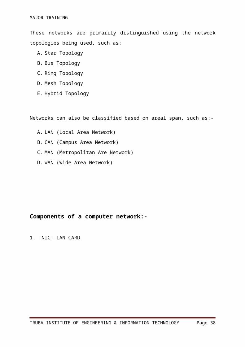
Components of a computer network:-
1. [NIC] LAN CARD
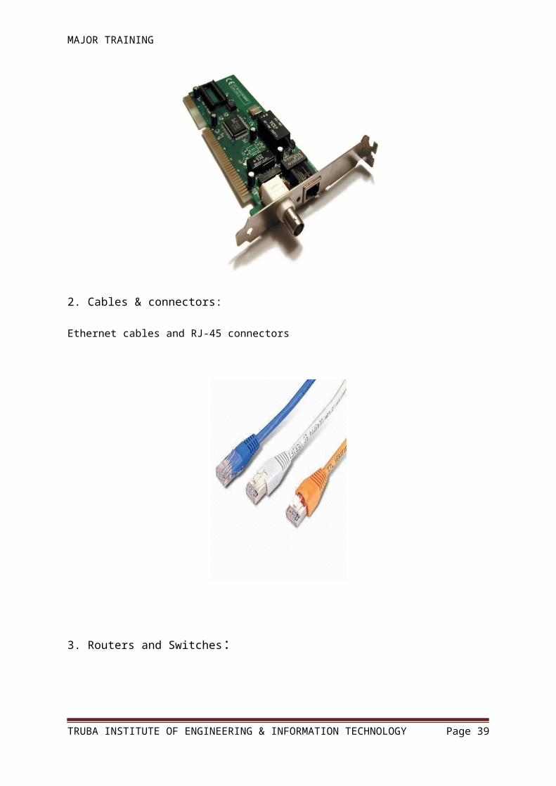
2. Cables & connectors:
Ethernet cables and RJ-45 connectors
TRUBA INSTITUTE OF ENGINEERING & INFORMATION TECHNOLOGY Page 29
MAJOR TRAINING
3. Routers and Switches:
TRUBA INSTITUTE OF ENGINEERING & INFORMATION TECHNOLOGY Page 30

MAJOR TRAINING
The OSI Reference Model:-Working of network systems is conceptually based on the OSI Reference Model, prepared by
the ISO.
The model itself comprises of 7 different layers; viz.
The TCP/IP Protocol Stack:-
TRUBA INSTITUTE OF ENGINEERING & INFORMATION TECHNOLOGY Page 31
MAJOR TRAINING
TCP/IP uses the Department of Defense (DoD) model, which describes communications in
only four layers, shown in the figure. Each successively higher layer builds on the functions
provided by the layers below
Application Layer The highest layer; defines the manner in which applications interact with the network—
including databases, e-mail, and terminal-emulation programs using Application layer
protocols similar to Lightweight Directory Access Protocol (LDAP), Simple Mail Transfer
Protocol (SMTP), and Telnet.
Presentation Layer Defines the way in which data is formatted, presented, converted, and encoded.
Session Layer :Coordinates communications and maintains the session for as long as it
isneeded—performing security, logging, and administrative functions.
Transport Layer Defines protocols for structuring messages and supervises the validity of the transmission by
performing error checking.
Network Layer TRUBA INSTITUTE OF ENGINEERING & INFORMATION TECHNOLOGY Page 32
MAJOR TRAINING
Defines data-routing protocols to increase the likelihood that the information arrives at the
correct destination node.
Data Link Layer Validates the integrity of the flow of the data from one node to another by synchronizing
blocks of data and controlling the flow.
Physical Layer Defines the mechanism for communicating with the transmission medium and the interface
hardware.
IP addressing and subnetting:-
IP Addressing
TCP/IP requires that each interface on a TCP/IP network have its own unique IP address. An
IPv4 address is a 32-bit number, usually represented as a four-part decimal number with each
of the four parts separated by a period or decimal point. You may also hear this method of
representation called dotted decimal or dotted quad decimal. In the IPv4 address, each
individual byte, or octet as it is sometimes called, can have a value in the range of 0 through
255.
NOTE:-
TRUBA INSTITUTE OF ENGINEERING & INFORMATION TECHNOLOGY Page 33

MAJOR TRAINING
A value of 126 or less indicates a Class A address.
The first octet is the network number; the next three, the host ID.
A value of 128 through 191 is a Class B address.
The first two octets are the network number, and the last two are the host address.
A value of 192 through 223 is a Class C address.
The first three octets are the network address, and the last octet is the host address.
A value of 224 through 239 is a Class D multicast address.
Again, there are no network or host portions to multicast addresses.
A value greater than 239 indicates a reserved Class E address.
Subnetting:-
An IP subnet modifies the IP address by using host ID bits as additional network address bits.
In other words, the dividing line between the network address and the host ID is moved to the
right, thus creating additional networks but reducing the number of hosts that can belong to
each network.
Advantages of subnetting:-
It minimizes network traffic, decreasing congestion.
It isolates networks from others.
It increases performance.
It optimizes use of IP address space.
It enhances the ability to secure a network.
Resource Sharing and Remote Access Services:-Network resources may be utilized to share files using Windows’ File sharing services
(based on the SMB/CIFS protocol) FTP / HTTP, etc.
Network resources may also be utilized to provide remote access using Command-line
utilities such as TELNET Graphical applications using RDP, VNC, etc.
TRUBA INSTITUTE OF ENGINEERING & INFORMATION TECHNOLOGY Page 34
MAJOR TRAINING
Routing Basics:- The major task of the router is to perform packet routing.
This is done by examining the router’s routing table present it its memory.
The routing table has to be populated with routes to different networks.
This is achieved either statically or dynamically.
There are different ways to populate the routing table with routes to different networks, as
follows:-
Route to local networks using the directly connected interfaces is created automatically.
Routes can be added statically (static routing).
Routes can be added dynamically using routing protocols (dynamic routing); ex: RIP,
EIGRP, OSPF.
Introduction to The Cisco Router:-Cisco provides various series and models of routers geared towards different types of
customer and requirements. Some of them just do routing whereas others provide some other
functions such as Wireless connectivity, Security features and Voice-over-IP services.
Cisco’s ISR series routers are example of routers that provide various services.
The Cisco Router has three types of memory-
The FLASH memory holds the Cisco IOS (Internetwork Operating System).
The NVRAM memory holds the startup-config.
The DRAM memory holds the running-config.
There are various modes of working within the Cisco router IOS:-
TRUBA INSTITUTE OF ENGINEERING & INFORMATION TECHNOLOGY Page 35
MAJOR TRAINING
The initial setup mode is lauched if either the startup-config is not present or has been
disabled from loading
The user mode
The privilege mode
The global configuration mode
Within the global configuration mode lies several specific configuration modes
The router requires its O.S. called the IOS to boot up. Once booted, the router can be
configured using several commands entered in one of its modes. These configurations are
saved temporarily within the DRAM in the file ‘running-config’. Hence, we need to save
them permanently within the NVRAM in the file ‘startup-config’
Managing the Cisco router through its console line:-
TRUBA INSTITUTE OF ENGINEERING & INFORMATION TECHNOLOGY Page 36

MAJOR TRAINING
TRUBA INSTITUTE OF ENGINEERING & INFORMATION TECHNOLOGY Page 37
MAJOR TRAINING
Implementing Basic security: Securing the user mode using telnet/console line.
Securing the privilege mode.
Commands within the router console:
Router>enable
Router#configure terminal
Router(config)#hostname Router1
Router1(config)#enable password 123
Router1(config)#enable secret cisco
Router1(config)#line con 0
Router1(config-line)#password console
Router1(config-line)#login
Router1(config-line)#exit
Router1(config)#line vty 0 4
Router1(config-line)#password telnet
Router1(config-line)#login
Router1(config-line)#exit
Router1(config)#exit
Router1#copy running-config sta
Router1#copy running-config startup-config
Router1#show running-config
Router1#show startup-config
Router1#reload
Implementing static routing:-TRUBA INSTITUTE OF ENGINEERING & INFORMATION TECHNOLOGY Page 38
MAJOR TRAINING
Router1 IP addressing:-
Router>enable
Router#configure terminal
Router(config)#hostname Router1
Router1(config)#int fastEthernet 0/0
Router1(config-if)#ip address 192.168.1.1 255.255.255.0
Router1(config-if)#no shutdown
Router1(config-if)#exit
Router1(config)#interface serial 0/0
Router1(config-if)#ip address 192.168.2.1 255.255.255.0
Router1(config-if)#clock rate 64000
Router1(config-if)#no shutdown
Router1(config-if)#^Z
Router1#copy running-config startup-config
TRUBA INSTITUTE OF ENGINEERING & INFORMATION TECHNOLOGY Page 39