hardware project-based microwave engineering …web.cecs.pdx.edu/~campbell/mttoct2012.pdf ·...
TRANSCRIPT

Hardware Project-Based
Rick Campbell
Portland State University
Microwave Engineering Education

Example Project 50 MHz 10 mW Sig Gen
Analyzed in class Winter 2009
Commercial Product here:
www.kangaus.com/6and2_meter_cw_source.htm

Educating an Engineer
MathPhysics
Familiarity with stuff
Prerequisites:
Engineers use math, physics, and experience to build models
Use model to understand and optimize “The Real Thing”
Curiosity
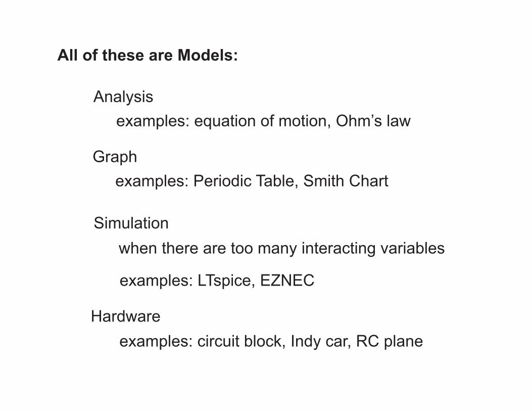
Analysis
Simulation
All of these are Models:
Hardware
examples: equation of motion, Ohm’s law
when there are too many interacting variables
examples: LTspice, EZNEC
examples: circuit block, Indy car, RC plane
Graphexamples: Periodic Table, Smith Chart

Ironic Note:
In Engineering, the model is often more expensive than the real thing....

Get them working
What do we do with Models?
Break them
Validate them against reality
Use new model to improve solution to real problem
Think about them
Evolve them
Engineer’s essential tool in applying the Scientific Method
But the art of the hardware model has fallen from favor--a victim of perceived expense and academic demographics.
In modern Engineering Education, we emphasize Analysis, simulation, and lovely graphs presented in Power PointPresentations.
Analysis, simulation, and lovely graphs without working hardware are scholarly, but irrelevant.
Playing with Hardware without analysis, simulation, and graphs of model vs. measurement is tinkering.
A person who embraces all of the above is scholarly, relevant, enjoys work, and can probably get your car running again by tinkering under the hood.

How do we learn?
Role of Hardware in Learning
Cool! How does it work?
What comes first, and when?
“Active Learning”
Cool! How can I apply this?
Hardware first:
Analysis first:

Honorable Mention:
Use of the Norcal 40 HF transceiver to teach undergraduate Electrical Engineering
Project Based RF Design course, with 40+ new amateur radio licenses in the past year alone
Dave Rutledge at Cal Tech
Zoya Popovic at UC Boulder
Robert Caverley at Villanova
A decade of using RF hardware projects in undergraduate teaching.

And the winner is....
(arduino synthesized drum roll)

And the winner is....
the students, of course.
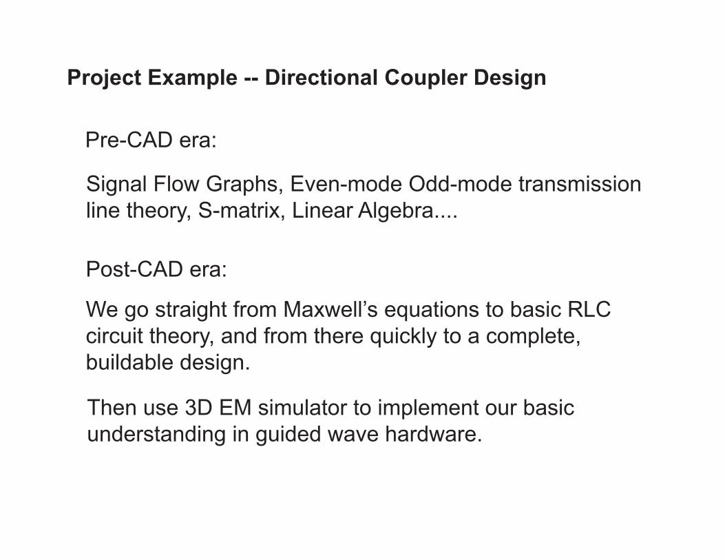
Project Example -- Directional Coupler Design
Signal Flow Graphs, Even-mode Odd-mode transmission line theory, S-matrix, Linear Algebra....
We go straight from Maxwell’s equations to basic RLC circuit theory, and from there quickly to a complete, buildable design.
Pre-CAD era:
Post-CAD era:
Then use 3D EM simulator to implement our basic understanding in guided wave hardware.
Since this is a presentation and not a class, we’ll skip the Maxwell’s equations, vector calculus, and complex algebra, but make a few observations:
Inductance is a volume in space with Magnetic fields. We calculate inductance by integrating over the volume--not the wire.
Capacitance is a volume in space with Electric Fields. We calculate capacitance by integrating over the volume--not the metal plates.
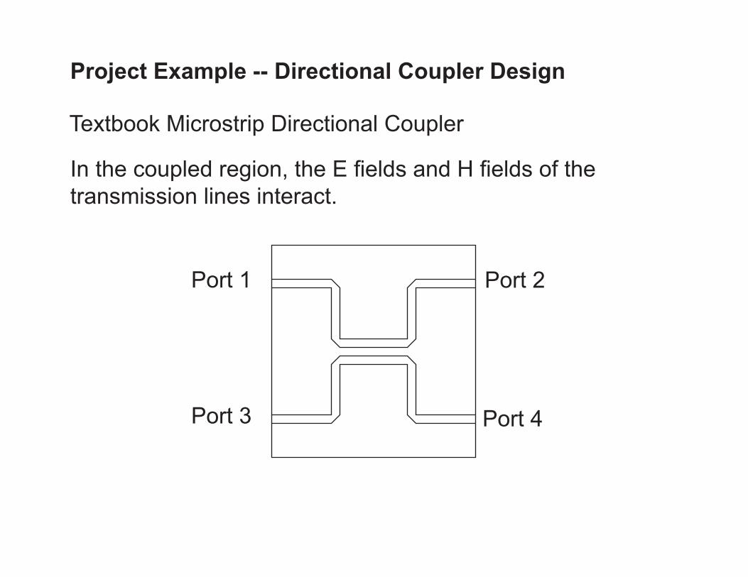
Project Example -- Directional Coupler Design
In the coupled region, the E fields and H fields of the transmission lines interact.
Textbook Microstrip Directional Coupler
Port 1 Port 2
Port 3 Port 4

Port 1 Port 2
Port 3 Port 4
To analyze, terminate all ports in characteristic impedance R

H field coupling is modeled with a coupled inductor
Now replace the microstrip version with a circuit model:
E field coupling is modeled with a capacitor
Port 1
Port 2
Port 3 Port 4
coupler model
note the stuff we left out
“Active Learning”
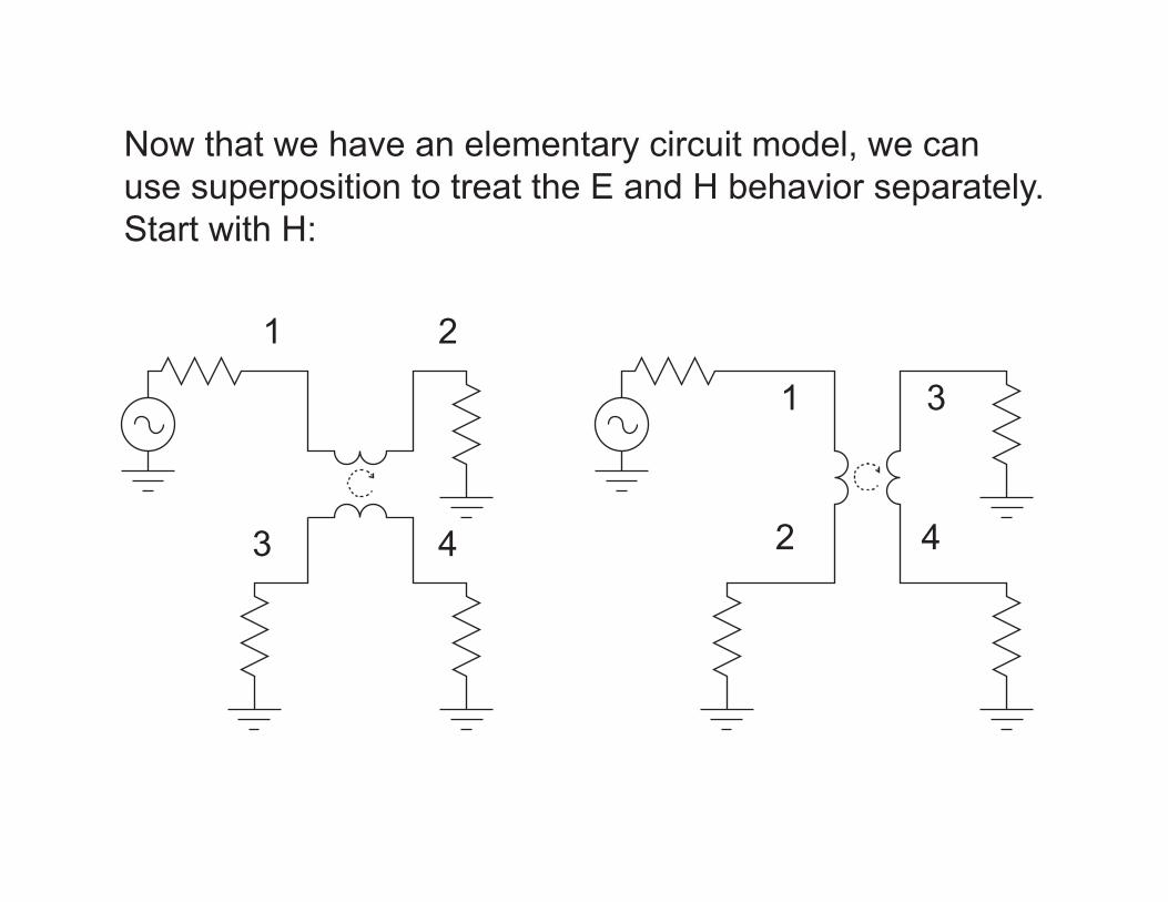
Now that we have an elementary circuit model, we can use superposition to treat the E and H behavior separately. Start with H:
1 2
3 4
1
2
3
4
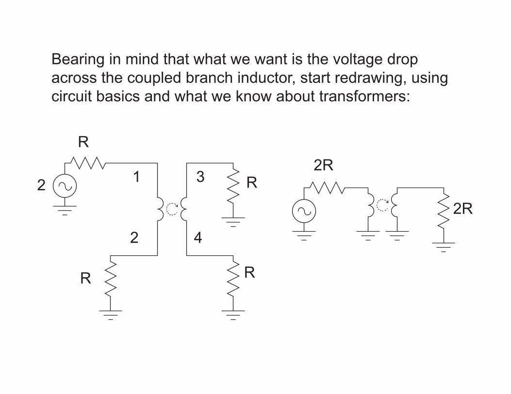
Bearing in mind that what we want is the voltage drop across the coupled branch inductor, start redrawing, using circuit basics and what we know about transformers:
1
2
3
4
R
R
R R
2R
2R2
2R 2R L
ideal
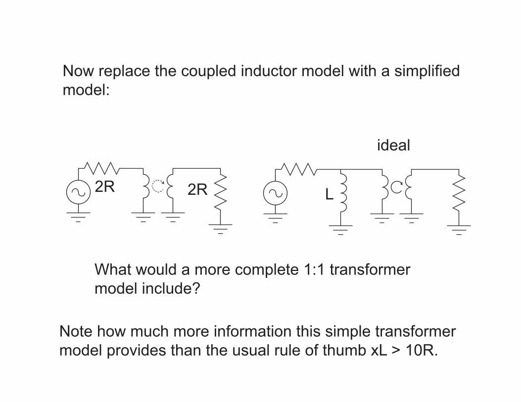
Now replace the coupled inductor model with a simplified model:
What would a more complete 1:1 transformer model include?
Note how much more information this simple transformer model provides than the usual rule of thumb xL > 10R.
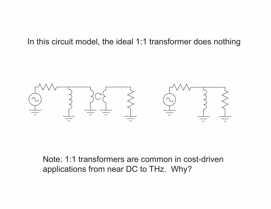
In this circuit model, the ideal 1:1 transformer does nothing
Note: 1:1 transformers are common in cost-drivenapplications from near DC to THz. Why?

Finally, invoke Thevenin equivalent circuit to obtain simple circuit model for the voltage drop across the inductor:
2R
2R2
R
1 L VL
+
-
Exercise for the student: write the expression for VL
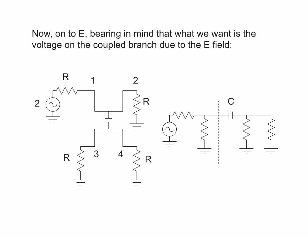
Now, on to E, bearing in mind that what we want is the voltage on the coupled branch due to the E field:
1 2
3 4
R
R
R R
C2
R
2 R R R
C R/2
R/2
C
1
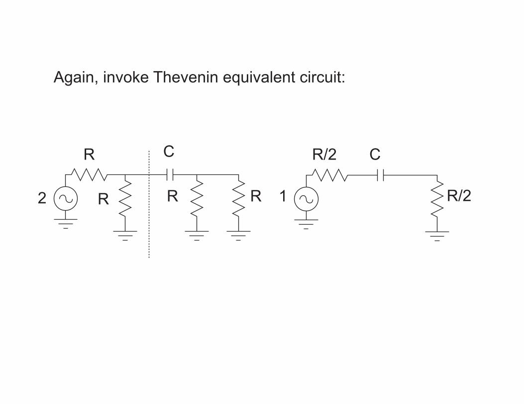
Again, invoke Thevenin equivalent circuit:
R
C1
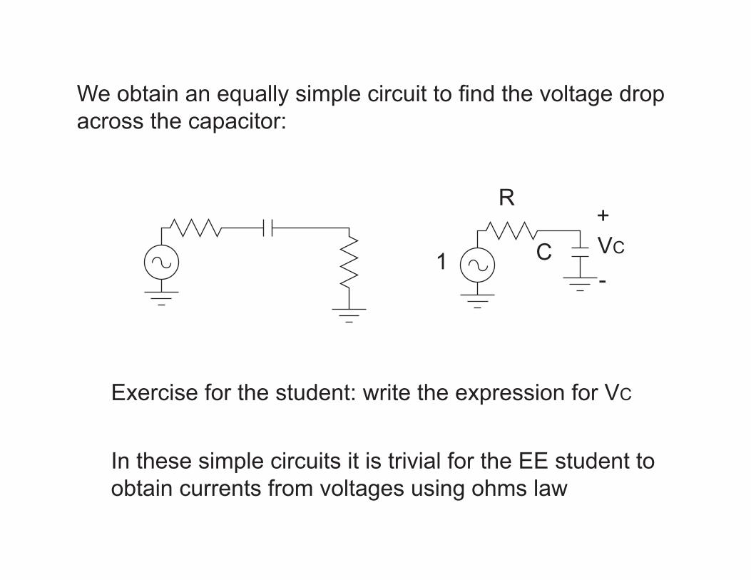
We obtain an equally simple circuit to find the voltage drop across the capacitor:
VC
+
-
In these simple circuits it is trivial for the EE student to obtain currents from voltages using ohms law
Exercise for the student: write the expression for VC

It is less trivial when those currents and voltages aresubstituted back into the original R C coupled L network...
...but it is still a basic circuit analysis problem, and a few pages of careful algebra provide a result that agrees with the LTspice simulation.
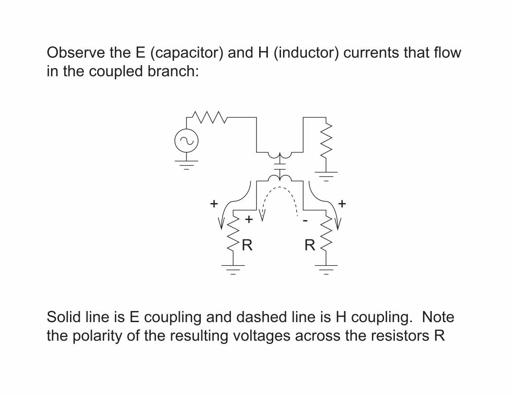
Observe the E (capacitor) and H (inductor) currents that flow in the coupled branch:
+ ++ -
Solid line is E coupling and dashed line is H coupling. Note the polarity of the resulting voltages across the resistors R
R R
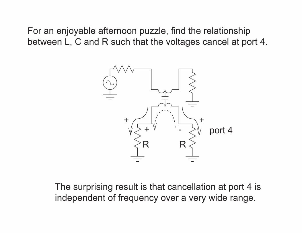
For an enjoyable afternoon puzzle, find the relationshipbetween L, C and R such that the voltages cancel at port 4.
+ ++ -
The surprising result is that cancellation at port 4 isindependent of frequency over a very wide range.
R Rport 4

Now obtain the voltage at port 3 under the R, L, and Cconstraint...wait...you’re still working on the last puzzle?
+ ++ -
Hint: the voltage at port 3 rises at 6 dB per octave when a small amount of signal is coupled.
R Rport 4
Why is it only 6 dB/octave with both E and H coupling?
port 3
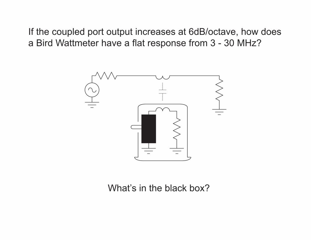
If the coupled port output increases at 6dB/octave, how does a Bird Wattmeter have a flat response from 3 - 30 MHz?
What’s in the black box?

Bird Wattmeter measuring forward power into load Z
Z
50 uA meter
RC
detector diode
Z
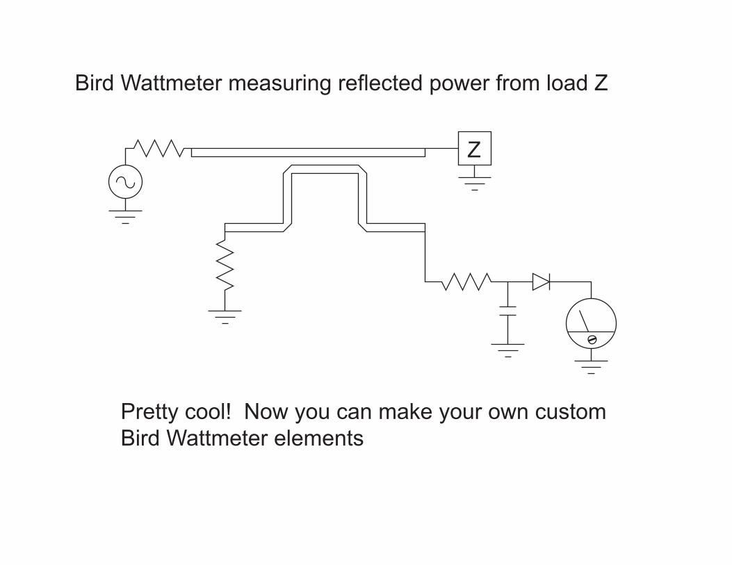
Bird Wattmeter measuring reflected power from load Z
Pretty cool! Now you can make your own customBird Wattmeter elements

ZL
C
R
L = R C2Null when:
Generic Directional Coupler with Detector
The Dark Side of Measurements.....
About 5 years ago a student designed and built a one-port network analyzer to tune up the input circuit of his classproject receiver.
Another student connected the class receiver and transmitter to a half wave dipole and communicated with another station 60 miles away.
Two students guest lectured, one speaking while the other started from scratch and built the complete working project.
The Bright Side.....
Exercise: Design, build, and measure a directional coupler forward and reverse power sensor to optimize a 50 MHzantenna driven by a 10 mW signal source.

Thank you for your attention and participation. Come down and visit me at my Office at Portland State University:
Fourth Avenue BuildingSuite 20 Faculty OfficesOffice 20-10