guide to the srx 800 telemetry receiver - fccid.io · lotek wireless — user’s manual guide to...
TRANSCRIPT

L O T E K W I R E L E S S — U S E R ’ S M A N U A L
Guide to the SRX 800 Telemetry Receiver
Lotek Wireless Inc. 115 Pony Drive
Newmarket Ontario Canada L3Y 7B5
www.lotek.com 905-836-6680
Manual, Preliminary
L O T E K W I R E L E S S — S R X 8 0 0 U S E R ’ S M A N U A L

W E L C O M E T O T H E S R X 8 0 0 The SRX800 receiver is used to scan frequencies and antennas (radio antennas and/or hydrophones) and to record data collected from Lotek transmitters. Some of the features that are offered in the SRX800 are:
• One serial port for connecting to a computer (use null-modem cable to connect to PC, standard RS-232 cable to connect to a modem).
• One USB port for connecting to a computer
• 1 kHz channel spacing
• Non-volatile flash memory
• 9 V power supply via 6 x C cell Alkaline 1.5 V batteries or external power supply (9 V, 1 A)
• Up to 16 Mbytes of data storage capacity (equivalent to more than 1 million data records)
• Ability to simultaneously monitor a group of antennas
• Integrated GPS clock and ability to obtain 2D positions
• Ability to create Configurations that store all settings
• Ability to filter data by accepting or rejecting channels and/or IDs
These factors determine how a receiver should be configured to meet the requirements of a study:
• Number of deployed transmitters
• Size of deployment area
• Number of frequencies
• Number of antennas (radio antennas or hydrophones)
• Amount of radio or acoustic noise in the area

Guide to the SRX800 Receiver Preliminary
A B O U T T H I S M A N U A L
For a flow-chart style layout to all the features accessible through the receiver’s keypad, please consult the Guide to the SRX Keypad and LCD Display manual.
This manual does not cover communicating with the receiver using the SRX Host application. Please refer to the Guide to the SRX800 Host Application manual for details.
T E C H N I C A L S P E C I F I C A T I O N S Operating Voltage Range 8-10 V DC (nominal 9 V)
Operating Current 250-450 mA @ 9 V
Battery Life
(6 x C cell 1.5 V Alkaline) Standard:
16 hrs. @ 20°C (LCD back light off)
12 hrs. @ 20°C (LCD back light on)
Operating Temperature Range -30°C to +50°C (LCD: from -5°C)
Weight ~2 kg (without batteries)
Size ~21.5 x 20.3 x 7.7 cm
Memory 4MB standard
16 MB optional
Program Memory Retention 5 years
Storage Temperature range -30°C to +55°C
Relative Humidity 95 %

Pollution Degree 2
Altitude Rating 2000 m
RF Parameters
Operating Frequency Range 138-176 MHz
VHF Input Impedance 50 Ohm
Channel Spacing 1 kHz
Frequency Stability 5 ppm
Sensitivity
Minimum discernible audio
level -150 dBm
Minimum discernible by
software -135 dBm

Guide to the SRX800 Receiver Preliminary
R E C E I V E R C A R E , M A I N T E N A N C E A N D S E R V I C E
Protect the SRX800 from excessive dust and moisture. If basic cleaning is required, wipe the housing and front panel gently with a soft cloth. To clean it more thoroughly, wipe the housing with a soft cloth dampened with a mild solution of soap and water. Do not allow any liquid to get inside the housing. Store the unit in a cool dry place when not in use.
Always use the head-phones provided by Lotek (stereo plug, 30 Ohm speakers). Upon inserting the plug, the audio signal will be disconnected from the main speaker, and routed through the head-phone speakers.
Always use the GPS antenna provided by Lotek (3 V active antenna)
Always use the external AC to DC wall power supply provided by Lotek. Do not use other power supplies, even if they provide the correct 9 V DC voltage! Check the LED on the rear panel: The LED should be green. If the LED is red, the receiver will not be energized, as most probably the improper AC-Dc is used.
Turn off receiver when removing or replacing batteries
Insert batteries with the correct polarity.
Replace all batteries at the same time. Do not mix used and new batteries. Use only batteries from known reliable suppliers (e.g. Energizer, Panasonic, Duracell, etc.). Dispose used batteries in concordance with the applicable laws. Do not put them in the normal waste.
IMPORTANT: Do not open the receiver. The device is not supposed to be
serviced or repaired by users. It will be exclusively serviced by Lotek qualified technicians. In case of malfunction, contact Lotek, and arrangements will be made for sending the receiver back and having it serviced.
Warning: Do not use the telemetry receiver outside the specified conditions
stated by the manufacturer. The improper usage of the device may cause
performance alteration or damage. If this happens, contact Lotek for
service. See the warning symbol attached to the rear panel (see

picture on page 9) which has the following meaning: Caution, refer to
manual.

Guide to the SRX800 Receiver Preliminary
F R O N T P A N E L C O M P O N E N T S • Power On/Off and Volume Control knob (labeled OFF/VOL)
• 16-key pad
• 2-line by 24-character LCD screen
• Standard 1/8 inch (3.5 mm) headphone jack
• BNC jack for antenna (labeled ANT )- 50 Ohm
• Speaker for broadcast of detections located on the upper panel.
See below the front panel, with description:
BNC RF
VHF
Antenna
Input
3.5 mm
Head-phone
Jack
16 Key Pad On-Off Switch &
Volume Control
Knob
LCD Display
Handle (for
Belt)
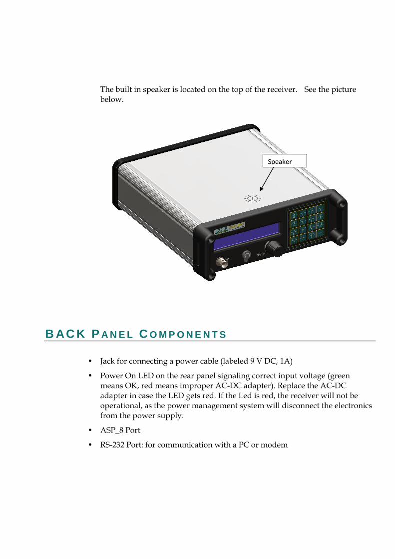
The built in speaker is located on the top of the receiver. See the picture below.
B AC K P A N E L C O M P O N E N T S
• Jack for connecting a power cable (labeled 9 V DC, 1A)
• Power On LED on the rear panel signaling correct input voltage (green means OK, red means improper AC-DC adapter). Replace the AC-DC adapter in case the LED gets red. If the Led is red, the receiver will not be operational, as the power management system will disconnect the electronics from the power supply.
• ASP_8 Port
• RS-232 Port: for communication with a PC or modem
Speaker

Guide to the SRX800 Receiver Preliminary
• USB Port: for communication with a PC
• GPS antenna connector for active GPS antenna
See below the back panel, with the descriptions:
Label with S/N,
model # and
warning sign
Regulatory Labeling
with e CE Mark
Battery
Compartment
Lid
Battery
Compartment
Lid
ASP_8
Port
Power ON
LED
9 V, 1A DC
Input
RS-232 USB
GPS Connector
for active GPS
antenna
P O W E R I N G T H E S R X 8 0 0 R E C E I V E R
P O W E R I N G T H E R E C E I V E R U S I N G T H E E X T E R N A L 9 V
D C I N P U T :
The receiver will operate with 6 x C cell 1.5 V Alkaline batteries, or via an external 9 V power supply which can be connected via a jack located on the rear panel. A wall-mount certified (UL, CSA and CE) power supply provided by Lotek must be used. The external power supply accepts 110 V, 60 Hz and 220 V 50 Hz. The appropriate adapters (also provided by Lotek) need to be used to accommodate the country specific outlet. The internal removable batteries will be disconnected upon plugging the external power supply in, so no energy will be consumed from the batteries in this case.
Upon removing the external DC connector, the receiver will continue operating on the internal batteries (if present). Contact Lotek for more information.
P O W E R I N G T H E R E C E I V E R U S I N G T H E I N T E R N A L
R E M O V A B L E B A T T E R I E S :
Each compartment (accessible from the back panel) can accommodate three 1.5 V C cell 1.5 V batteries.
To insert or replace the batteries, the following should be done (see also picture):
Turn receiver off
Remove 9 V DC power supply, if connected
Position receiver upside down, with the back panel up
Remove threaded lids
Remove the batteries from each compartment

Guide to the SRX800 Receiver Preliminary
Insert new batteries (three on each side), with the correct polarity, i.e. the positive terminal of the battery should be always up. This is also marked on the inside of the lid.
Re-attach threaded lids
Turn-on receiver, and check for normal operation
See the picture below describing the correct polarity of the batteries:
With new batteries, the receiver can operate continuously for up to 12 hours with the backlight on or up to 16 hours with the backlight off.
To insert or replace batteries, unscrew the round lids located on the receiver back panel. Each cylinder (left and right) can accommodate three 1.5 V cell batteries. The polarity of the batteries is marked. Always replace batteries at the same time. Do not mix new batteries with old batteries. Remove batteries if the receiver is stored for longer periods of time.
C CELL 1.5 V
BATTERY POSITIVE
TERMINAL UP
+ MARKING ON THE
INSIDE OF THE LID

T U R N I N G O N T H E R E C E I V E R Turn the OFF/VOL knob clockwise until a click is felt.
T U R N I N G U P T H E V O L U M E O N T H E R E C E I V E R To turn up the volume, turn the OFF/VOL knob clockwise

Guide to the SRX800 Receiver Preliminary
T Y P E S O F T R A N S M I T T E R S A Lotek transmitter uses a series of single-frequency pulses to communicate with the SRX800 receiver. Lotek radio transmitters operate at a frequency range of between 140 and 174 MHz. Three main types of transmitters are used:
• Coded ID Only Transmitters
• identified by a group of four pulses separated by specific amounts of time, which the receiver interprets to form the ID of that transmitter
• Coded Sensor Transmitters : - identified by a group of four pulses that can vary the amount of time between each pulse to convey sensor information (e.g. temperature, pressure).
• Beeper
• Transmitters : - identified as a single frequency pulse that is typically used in large animal studies. They are used to establish an approximate location of a collared animal, within a kilometer or so.

T H E K E Y P A D A N D L C D D I S P L A Y
K E Y P A D A N D D I S P L A Y S T R U C T U R E The keypad and LCD screen define the interface through which the receiver is programmed. The program is designed like a hierarchy. All aspects of the program are accessed through keys on the keypad.
The keypad is used to enter or select operating parameters, to input data, and to navigate through menus and pages. Every key, except Light, has two functions. Which function is accessible depends on the state of the receiver.
Keys labelled Setup, Log On, Info, Manual, Codelog, and Set Delta provide access to menus (note that in most cases there are also sub-menus). The Setup, Manual, and Codelog keys access modes. Through these modes, specific aspects of the receiver’s functionality can be enabled, disabled, or amended.
The LCD screen has a two-line display. It is used to display data and to request input, in the form of either a menu selection or an entry of a numeric value. Each screen the LCD presents is referred to as a page. Due to the limited size of the LCD, it is often necessary to spread out displayed information and menus across several pages. To scroll through multiple pages, use the right and left arrow keys or the END/ESC key.
The LCD display also provides current setting information. This information depends on whether the receiver is Online or Offline.
If the receiver is Online, the LCD shows the current settings within brackets after the page title. A new value can be entered.
Guide to the SRX800 Receiver Preliminary
If the receiver is Offline, the LCD shows the current settings after the title of a page, but there is no provision for a new value to be entered.
L O G G I N G O N T O T H E R E C E I V E R Logging on to the receiver provides the ability to change the state of the receiver. When a log on password is provided the receiver is considered Online. If no password is provided (logged off) then the receiver is Offline. The differences between Online and Offline are described below:
• Offline: the receiver allows read-only access, which means that most inputs are not allowed (unless a log on password is provided). The only allowed input is the Reset Password function.
• Online: the receiver allows full write access, which means that all functionality and input capabilities are available.
Log on to the receiver via:
Log On > 1)Log On or Log On > 2)Log On via Factory Password.
Wait a few seconds for the changes to be accepted and then the receiver returns to the last state that was active (e.g. scan) or the start page.
The log on password is always “123456” unless it is changed via Setup >
3)Change Password.
Logging on via the factory password allows you to log on quickly, provided the factory password (“123456”) is being used. This feature is convenient if you do not need or want to have a specific confidential password.
Logging on can be done at any time during operation of the receiver, except while using the Info key and its menu items.
L O G G I N G O F F Logging off can be done at any time during operation of the receiver. Data collection can continue while limiting access to settings via a password. Logging off means the receiver is Offline.
Log off from the receiver via:

Guide to the SRX800 Receiver Preliminary
Log On > 2)Log Off
or
Log On > 3)Temporarily Log Off
The receiver accepts the changes after a few seconds and LCD returns to the start page (the first screen shown after the receiver is turned on).
Temporarily logging off creates a restriction, whereby logging on is accessible only from the receiver keypad and no longer accessible from the SRX Host software, except via the Host’s Keypad Simulator.
C H A N G I N G A L O G O N P A S S W O R D Changing the log on password can be done only in Setup Mode and when the receiver is Online.
Changing the password requires that the old password be entered, followed by the new one. The receiver automatically places a slash [/] between the two passwords as they are entered. The password must consist of six numbers.
Change the password via:
Setup > 3)Change Password
R E S E T T I N G A L O G O N P A S S W O R D Resetting the log on password can be done only in Setup Mode and when the receiver is Offline. This feature is not normally used, except to provide a recovery mechanism if the current password has been lost or forgotten. In such an event, Lotek support staff, given the receiver’s serial number and the six-digit number associated with the Reset Password function, can provide a password that can be used to log on to the receiver.
Reset the password via:
Setup > 3)Reset Password

Guide to the SRX800 Receiver Preliminary
U S I N G T H E I N P U T K E Y S
E N T E R Once a value is entered for an input, pressing the Enter key causes the receiver to accept that input and save it, provided that the receiver is Online.
E N D / E S C The END/ESC key is used for menu navigation, for cancelling incomplete inputs, and for stopping receiver actions in Online mode.
For navigation, it provides the ability to return to the last menu accessed. For example, after enabling TOA, press the END/ESC key to return to the Scan Options menu (where the TOA feature was accessed).
The END/ESC key can also be used to cancel an input before it is entered completely (e.g, while entering 148.08_). Many inputs are accepted automatically as soon as the number receives the expected number of characters. If a number is only partially entered and you decide to cancel that input, press the END/ESC key to cancel it.
If the receiver is Online, the END/ESC key can also be used to stop a current active state of the receiver (e.g. GPS position acquisition or a Scan Cycle). This action is dependant on the status of the receiver. For example, if the receiver is not trying to acquire a GPS position, then the END/ESC key has no effect. If the receiver is Offline, then the END/ESC key has no effect.
N U M B E R S Keys that have a number (0 through 9) in their lower portion are used in two ways: to select menu items and to enter in numeric values.
All available menu items have a number in front of them (e.g. 1) Gain). To select a menu item, press the corresponding number on the keypad (e.g. press 1 to go to the Gain menu).
When prompted for a numeric input, use the keypad numbers to enter a value.
D E C I M A L The lower portion of this key provides the decimal point needed for many input values.
P L U S / M I N U S S I G N Plus (+) or minus (-) signs are provided at the beginning of some input prompts (e.g. >+). Minus signs are necessary when entering the GMT correction into the receiver.
To change a sign, press the +/- key once.

Guide to the SRX800 Receiver Preliminary
U S I N G T H E N A V I G A T I O N K E Y S
R I G H T A R R O W A N D L E F T A R R O W The Right and Left Arrow keys are used for navigating forwards and backwards between menu pages. If more than one page is available, a “-->” or a “<--” symbol appears in the lower-right corner of the LCD. Multiple pages are used to accommodate the limitations of a two-line display; any menu items or inputs that exceed this space must be spread out.
For example, to see all of the menu options from the Search page in Manual
mode, use the right arrow to scroll through the next two pages of menu options.
The only time an arrow prompt in the lower right corner is not provided is when the receiver’s battery is low. In this case, a small square icon is provided indicating low battery status.
B S P A C E The Backspace key erases the value of an input one number/value at a time. This is similar to using the backspace key on a computer keyboard.

U S I N G T H E I N F O K E Y The Info key provides access to:
• Battery voltage (main and backup) [1)Bat]
• Available memory (in Kilobytes) [2)Mem]
• Configuration settings (Scan Time and Code Set) [5)Cfg]
• Service information (receiver’s Serial Number and number of hours in operation since last servicing) [6)Service]
• The factory password (123456) [7)Factory Password]
• Ability to answer an incoming call via the Modem [8)Answer Incoming Call]
When accessing the Info key menu items, it is not possible log on to the receiver; these features are mutually exclusive.
A N S W E R I N G A N I N C O M I N G C A L L This feature is provided for testing and troubleshooting purposes. When a modem is being used to access the receiver, it rings when a call is made. The receiver is programmed to automatically answer all calls made. If the receiver does not answer after the modem rings four or more times, there may be a problem with the auto-answer feature.
However, the call can still be answered via Info > 8)Answer Incoming Call.

Guide to the SRX800 Receiver Preliminary
A D J U S T I N G F R E Q U E N C Y A N D G A I N
A new frequency can be selected using the Up or Down Arrows. The amount of increment or decrement is specified by Set Delta for frequency (see section called Set Delta for details).
A new gain can be selected using the Up or Down Arrows. The amount of increment or decrement is specified by Set Delta for gain (see section called Set Delta for details).
U S I N G N O I S E B L A N K I N G ( N B L A N K ) Noise blanking enhances the receiver’s audio performance by suppressing the receiver’s audio response except when a signal is detected.
This helps prevent auditory fatigue when using the receiver for extended periods of time in aircraft or other noisy environments.
Press the key labelled NBlank to enable and disable noise blanking.
T U R N I N G O N T H E B A C K L I G H T Press the Light key to switch the LCD backlight on or off. Using the light consumes more power, but it may be necessary in low-light conditions to see the LCD display.

S E T D E L T A Set Delta is used to set the increments for frequency and gain, so that when the Up and Down Arrows for frequency and gain adjustment are used, the receiver knows the amount it should advance up or down.
S E T D E L T A F O R F R E Q U E N C Y
When adjusting the frequency manually, the receiver increases or decreases the frequency (kHz) in use by an amount equal to the Frequency Delta increment.
Set this increment via: Set Delta > 1)Freq
S E T D E L T A F O R G A I N
When incrementing gain manually, the receiver increases the gain in use by an amount equal to the Set Delta gain increment.
Set this increment via: Set Delta > 2)Gain
G P S The GPS key provides the ability to acquire a GPS fix. This data is not stored by the receiver (except when accessed in Codelog mode). This feature should be tested before the enabling the GPS feature (see chapter Codelog Mode, section Enabling/Disabling GPS Positioning) by starting a scan via Codelog Mode. Testing the feature verifies that the receiver is able to take a valid 2D position. When testing, ensure that the GPS antenna supplied with the receiver is connected to the receiver and that the antenna has a clear view of the sky.
CRTO cannot be used with the GPS 2D-positioning feature of the receiver; however it still allows the GPS clock to function.

Guide to the SRX800 Receiver Preliminary
S T A R T I N G A G P S A C Q U I S I T I O N Start acquiring a GPS 2D position by pressing the GPS key on the keypad (key number 4). While attempting to acquire a position, the display shows the number of satellites as they are found.
If a valid position is acquired, the following information is provided on the display: Latitude, Longitude, current date, current GMT time, the number of satellites used, HDOP, and PDOP. The display flips back and forth between showing the Latitude and Longitude for four seconds and the satellites, HDOP and PDOP information for two seconds. Either the time or date is also shown on the display and it is updated every five seconds.
GPS cannot be used if the receiver is logged off. However, it is possible to log off from the receiver while the receiver is attempting to acquire a GPS position. When logging back on, the display shows the results of the GPS position.
S T O P P I N G A G P S A C Q U I S I T I O N Press the END/ESC key to stop acquiring a GPS position.
S E T U P M O D E
3
C H A P T E R O V E R V I E W Setup Mode allows global settings to be changed and applied. Global settings are those settings that affect how the receiver operates. Setup Mode allows you to:
• Configure communication settings (serial and modem)
• Reset communication settings to the default Factory Settings
• Enter the Local Date, Time, and GMT correction
• Reset or change the log on password
After the Setup key is pressed, the LCD shows three main menu items:
1)Comm, 2)Time, 3)Reset Password
This section is organized by these three menu items.
1 ) C O M M
C O N F I G U R I N G S E R I A L P O R T S E T T I N G S
The serial port must have its baud rate (for modem), parity, data bits, and stop bits defined. If these settings are not changed, then the default values are used, which are: Baud rate= 115200, Parity= No, Data bits= 8, and Stop bits= 1.
To define each of these parameters:
• Baud Rate: Select one of the nine different baud rates.
Setup > 1)Comm > 1)Configure > 1)Serial I (or) 2)Serial II > 1)Baud Rate
• Parity: Select to have no parity, odd parity, or even parity.
Setup > 1)Comm > 1)Configure > 1)Serial I (or) 2)Serial II > 2)Parity
• Data Bits: Select either 7 or 8 data bits.
Setup > 1)Comm > 1)Configure > 1)Serial I (or) 2)Serial II > 3)Data Bits
Guide to the SRX800 Receiver Preliminary
• Stop Bits: Select either 1 or 2 stop bits.
Setup > 1)Comm > 1)Configure > 1)Serial I (or) 2)Serial II > 4)Stop Bits
The receiver also needs to know if the serial port is going to be used for connecting to a modem (see Configuring Modem Settings for details).
C O N F I G U R I N G M O D E M S E T T I N G S The modem must be connected to Serial I. Serial I must have the appropriate baud rate set to be compatible with the speed of the modem. The port baud rate should be set at or below the actual throughput of the line, to avoid overloading the modem’s internal buffers.
For example, if the modem is capable of communicating with the receiver at 115200 baud, but the actual telephone line speed is 57600, the Serial I setting should not exceed 57600.
Access modem settings via:
Setup > 1)Comm > 1)Configure > 1)Serial I > 5)Modem
Three actions are associated with the modem: assigning Serial I to the modem, viewing the CMDS for the modem, and initializing the modem.
Details on these are provided below.
ASSIGNING A MODEM TO SERIAL I Assign a serial port via:
Setup > 1)Comm > 1)Configure > 1)Serial I > 5)Modem > 1)Has Modem
Select Yes or No.
VIEWING THE CMDS
View the CMDS via:
Setup > 1)Comm > 1)Configure > 1)Serial I > 5)Modem > ViewCMDS
CMDS stands for Command String and it is used to initialize the modem. The CMDS may need to be viewed if the modem is not working or if data transfer is very slow. If the CMDS parameters are not appropriate for the modem being used, they can be changed using the SRX Host software. To find out what CMDS parameters the modem needs, consult the modem’s user guide or Lotek Wireless Inc. for details.
INITIALIZING THE CMDS FOR THE MODEM CMDS stands for Command String and is used to initialize the modem.
As soon as a modem is connected to the receiver and the receiver is Online, the CMDS parameters are sent to the modem. If no modem is connected, a “No Modem, please select it via Setup/Comm” message shows on the LCD.
If the modem’s CMDS parameters are edited via the SRX Host while the modem is connected, then the modem cannot function properly. Two ways to correct this are: 1)initialize the modem, or 2) unplug the modem and then plug it back into the receiver. For the latter, the receiver sends the new CMDS to the modem as soon as the modem is reconnected to the receiver (like a refresh).
Initialize the modem via:
Setup > 1)Comm > 1)Configure > 1)Serial I > 5)Modem > 3)Initialize
If a strictly RF modem is being used, then Serial II can be used.
S E T T I N G D E F A U L T F A C T O R Y S E T T I N G S View the default factory settings via:
Setup > 1)Comm > 2)Factory Settings
The factory default settings are available for Baud Rate, Parity, Data Bits, and Stop Bits. The default settings are shown in brackets in the display when this menu item is selected.
The factory default settings can be set for either Serial I or Serial II, or both, via:
Guide to the SRX800 Receiver Preliminary
Setup > 1)Comm > 2)Factory Settings > 1)Serial I (or) 2)Serial II
2 ) T I M E
E N T E R I N G T H E G M T C O R R E C T I O N For the GPS feature of the receiver to update its clock properly, it must know the GMT correction for the receiver’s location.
Enter the GMT correction via:
Setup > 2)Time > 1)GMT Correction
The time format is in hh/mm.
E N T E R I N G L O C A L D A T E A N D T I M E The receiver uses the local time and date in combination with the GMT correction so that data can be displayed in local time, even though the receiver works internally in GMT time.
Enter the date via:
Setup > 2)Time > 2)Local Date
The date format is in dd/mm/yy.
Enter the time via:
Setup > 2)Time > 3)Local Time
The time format is in hh/mm/ss and is based on a 24-hour clock (a.k.a. military time).
Guide to the SRX800 Receiver Preliminary
3 ) R E S E T / C H A N G E P A S S W O R D
C H A N G I N G A L O G O N P A S S W O R D Access to this feature is provided only in Setup Mode. A password can be changed only when the receiver is Online.
Changing the password requires that the old password be entered first, followed by the new password. The receiver automatically places a slash [/] between the two passwords as they are entered. The password must be made up of six numbers.
Change the password via:
Setup > 3)Change Password
R E S E T T I N G A L O G O N P A S S W O R D The Reset Log On Password feature is accessible only in Setup Mode. A password can only be reset if the receiver is Offline.
Typically, this feature is used only as a recovery mechanism if the current password is lost or forgotten. In such an event, Lotek support staff can provide a working log on password, if provided with the receiver’s serial number and the six digit number associated with the reset password function.
Reset the log on password via:
Setup > 3)Reset Password

M A N U A L M O D E
C H A P T E R O V E R V I E W Manual mode provides the ability to collect data without using a Configuration (see the Codelog Mode chapter for details on Configurations). In manual mode operation, data is not recorded by the receiver. Detections are indicated by pings or clicks emitted by the speaker on the receiver’s front panel. Adjust the volume by turning the OFF/VOL knob clockwise.
Use a quality isolating (monaural) headphone set when listening to weak signals or when working in environments with a lot of ambient noise.
Some of the receiver’s settings can be changed while in manual mode.
After selecting the Manual key on the keypad, three menu items become available:
1) Code Set, 2)Search (and) 3)Signal
The first menu item provides the ability to change the active code set. After selecting 1)Code Set, use the keypad to select the desired code set.
The other two menu items, Search and Signal, provide two different methods of starting a scan in manual mode and changing various settings that affect the scan.
Some settings, listed below, are the same in either Search or Signal:
• Starting a scan
• Setting the type of transmitter to scan (Beep/ID/Sensor)
Guide to the SRX800 Receiver Preliminary
• Changing the Set Delta frequency and/or gain
• Acquiring a GPS 2D position
• Entering a gain
• Setting the noise threshold
Settings that are unique to the Search menu item are:
• Pausing or resuming a scan
• Entering a minimum frequency
• Entering a maximum frequency
• Defining a frequency step
• Setting the scan time
Settings that are unique to the Signal menu item are:
• Changing the antenna port assignment for the master radio antenna and/or the hydrophone
• Changing the radio frequency
• Changing the acoustic frequency

1 ) C O D E S E T ( A N D D E T A I L S O N C O D E S ) A transmitter code is made up of four pulses that occur over three-pulse intervals. A pulse interval is the period of time that elapses between one pulse to the next. The three-pulse intervals are unique to every transmitter, so that the receiver can identify the transmitter.
To interpret the pulse intervals, the receiver references a library, called the Code Set. The code set used with the receiver specifies all the different combinations of pulse intervals that can exist, and it provides information to the receiver on how to interpret tags that transmit sensor data within that code set.
The receiver is configured with the required code set(s) for a study at the time of manufacture. Current code sets are Lotek 1, Lotek 2, Lotek 3, Lotek 4, and Lotek 5. The code set must be selected before data collection can proceed.
Lotek Code Sets and Firmware1 (“FIRMWARE”) are protected by copyright laws and international treaty provisions. LOTEK owns and retains all right, title, and interest in and to the FIRMWARE, including all copyrights, patents, trade secret rights, trademarks, and other intellectual property rights therein. Licensee’s possession, installation, or use of the FIRMWARE does not transfer any title to the intellectual property in the FIRMWARE and the Licensee will not acquire any right, title, or interest to the FIRMWARE except as expressly set forth in the Firmware License Agreement included with every system purchased.

Guide to the SRX800 Receiver Preliminary
1: Lotek Code Sets and Firmware includes, but is not limited by the following: Lotek-1 (also referred to as Lotek 1993 code set or 1993 code set), Lotek-2 (also referred to as Lotek 1994 code set or 1994 code set), Lotek-3 (also referred to as Lotek 2000 code set or 2K code set), Lotek-4 (also referred to as Lotek 2003 code set or 2003 code set) and Lotek-5.
S E L E C T I N G A C O D E S E T Code sets are accessed via: Manual > 1)Code Set.
Use the keypad to select the desired code set. If the receiver is Offline, then accessing the code set feature only provides current setting information.

2 ) S E A R C H
S T A R T I N G A S C A N V I A S E A R C H A scan cycle can be started via: Manual > 2)Search > 1)Start.
To stop a scan, press the END/ESC key.
When a scan is started from the Search menu, the receiver scans through a range of frequencies looking for a signal using the Frequency Step setting. The frequency step is the increment in kHz that the receiver uses to increase the frequency as a scan proceeds.
The frequency range is defined by entering a maximum frequency and a minimum frequency. After a scan is started, the receiver begins scanning the minimum frequency and then incrementing the frequency according to the frequency step until the maximum frequency is reached.
While scanning, the LCD shows the current frequency and the antenna being scanned. After a valid detection is made, the LCD also shows the transmitter’s ID, the time, the type of transmitter, and the signal strength.
If a valid detection is made on any frequency during the scan, the receiver continues scanning the frequencies for that transmitter until it finds a local maximum for that frequency, at which point it stops scanning and displays the maximum signal strength and the frequency at which it was found.
The local maximum is the frequency at which the signal strength is highest for a given transmitter.
Once a scan is stopped, four choices are available: exit Search, edit settings, pause the scan, or resume scanning.
S E L E C T I N G A C O D E S E T Code sets are accessed via Manual > 2)Search > 1)Start > 1)Code Set

Guide to the SRX800 Receiver Preliminary
Use the keypad to select the desired code set. If the receiver is Offline, then accessing the code set feature only provides the current setting information.
P A U S I N G A S C A N Pause a scan via
Manual > 2)Search > 1)Start > 0)Pause Scan
This function suspends the scan cycle on the frequency and antenna being scanned. The receiver does not change the frequency or antenna it was scanning when paused, but it does continue to log data for that frequency and antenna.
R E S U M I N G A S C A N Resume a scan via
Manual > 2)Search > 1)Start > 0)Resume Scan
The receiver uses the last settings applied during the pause, thereby replacing the previous values in the active configuration.
S E T T I N G T H E T Y P E O F T R A N S M I T T E R T O S C A N Set the type of transmitter to scan via:
Manual > 2)Search > 1)Start > 2) Show Beep/ID/Sensor
The type selected depends on the type that was selected before using this feature. For example, if the scan was showing Sensor (SEN) type transmitters, then pressing 2)Show Beep/ID/Sensor once causes the type to change to Beep. Pressing 2)Show Beep/ID/Sensor again switches the type to ID and so on.
No indication is given that the type of transmitter to scan has been changed. Press the Left Arrow once to go back to the first page to see that the type has been changed.
S E T D E L T A F O R F R E Q U E N C Y Set Delta is not used during a search. Refer to section Defining a Frequency Step, for details on how to define the gain increment during a search.
Set this increment via Manual > 2)Search > 1)Start > 3)Set Delta > 1)Freq

S E T D E L T A F O R G A I N When incrementing gain manually (by using the keys on the keypad), the receiver adds the Set Delta gain increment to the gain being used at the time the gain is adjusted up or down.
Set this increment via: Manual > 2)Search > 1)Start > 3)Set Delta > 2)Gain
S T A R T I N G A G P S A C Q U I S I T I O N To start acquiring a GPS 2D position, press the GPS key on the keypad (key number 4). While attempting to acquire a position, the display shows the number of satellites as they are found.
If a valid position is acquired, the following information is provided in the display: Latitude, Longitude, current date, current GMT time, the number of satellites used, HDOP, and PDOP. The display flips back and forth between showing the Latitude and Longitude for four seconds and the satellites, HDOP, and PDOP information for two seconds. Either the time or the date is also shown on the display and is updated every five seconds.
GPS cannot be used if the receiver is logged off. However, it is possible to log off from the receiver while the receiver is attempting to acquire a GPS position. When logging back on, the display shows the results of the GPS position.
Press the END/ESC key to stop acquiring a GPS position.
A D J U S T I N G F R E Q U E N C Y A N D G A I N
A new frequency can be selected with the Up or Down arrows. The amount of increment or decrement is specified by Set Delta for frequency (see the section Set Delta in Chapter 1 for details).

Guide to the SRX800 Receiver Preliminary
A new gain can be selected with the Up or Down arrows. The amount of increment or decrement is specified by Set Delta for gain (see the section Set Delta in Chapter 1 for details).
E N A B L I N G / D I S A B L I N G N O I S E B L A N K I N G ( N B L A N K ) Noise blanking enhances the receiver’s audio performance, especially in aircraft or other noisy environments, by suppressing the receiver’s audio response except when a signal is detected.
This helps prevent auditory fatigue when using the receiver for extended periods of time.
Press the NBlank key to enable or disable noise blanking.
E N T E R I N G A S P E C I F I C G A I N V A L U E During a search, the gain can be increased and decreased using the appropriate keys (see section on Adjusting Frequency and Gain above), but there are occasions when it is desirable to change the gain to a specific value for the particular antenna being scanned.
Enter this specific gain value via: Manual > 2)Search > 2)Gain
Immediately after the value has been entered, the receiver returns to the Search page.
E N T E R I N G A M I N I M U M F R E Q U E N C Y Enter the frequency at which the scan should start via:
Manual > 2)Search > 1)Start > 3)Min Freq
E N T E R I N G A M A X I M U M F R E Q U E N C Y Enter the frequency at which the scan should end via:
Manual > 2)Search > 1)Start > 4)Max Freq
Once the maximum frequency is met, the receiver starts scanning from the minimum frequency again.
D E F I N I N G A F R E Q U E N C Y S T E P The frequency step is the increment in kHz that the receiver uses to increase the frequency as a scan proceeds. Enter the value for the increment via:
Manual > 2)Search > 1)Start > 5)Freq Step
Starting a scan via Search means that the Set Delta frequency is not used. For Search the frequency step option is provided to set a frequency increment.
S E T T I N G T H E S C A N T I M E To specify how long the receiver should scan each frequency and antenna, enter a time in seconds via:
Manual > 2)Search > 1)Start > 6)Scan Time
S E T T I N G T H E N O I S E T H R E S H O L D The Noise Threshold is a minimum allowable detection signal strength. This means that if the receiver detects a pulse that has a signal strength equal to or less than the noise threshold, it is rejected and not used for further code processing.
Typically, the noise threshold is set to 30, but it should be set to reflect the environment in which a study is taking place.
Set the noise threshold via:
Manual > 2)Search > 5)Noise Threshold
The maximum noise threshold value that can be entered is 99.

Guide to the SRX800 Receiver Preliminary
3 ) S I G N A L
S T A R T I N G A S C A N V I A S I G N A L Scanning using Signal means that the receiver monitors only one frequency and one antenna until they are changed manually. The scan cannot be paused using Signal.
Start a scan via:
Manual > 3)Signal > 1)Start
S E L E C T I N G A C O D E S E T Codes sets are accessed via:
Manual > 3)Signal > 1)Start > 1)Code Set
Use the keypad to select the desired code set. If the receiver is offline, then accessing the code set feature only provides current setting information.
S E T T I N G T H E T Y P E O F T R A N S M I T T E R T O S C A N This is a toggle-type control. Set the type of transmitter to scan via:
Manual > 3)Signal > 1)Start > 2) Show Beep/ID/Sensor
The type selected depends on the type that was selected previously. For example, if the scan was showing sensor (SEN) type transmitters, then pressing 2)Show
Beep/ID/Sensor once causes the type to change to Beep. Pressing 2)Show
Beep/ID/Sensor again switches the type to ID and so on.
No indication is given that the type of transmitter to scan has been changed. Press the Left Arrow key once to go back to the first menu page to see that the type has been changed.
S E T D E L T A F O R F R E Q U E N C Y When adjusting the frequency manually, the receiver increases or decreases the frequency (kHz) in use by an amount equal to the Frequency Delta increment.
Set this increment via: Manual > 3)Signal > 1)Start > 3)Set Delta > 1)Freq
S E T D E L T A F O R G A I N When incrementing gain manually, the receiver increases the gain in use by an amount equal to the Set Delta gain increment.
Set this increment via: Manual > 3)Signal > 1)Start > 3)Set Delta > 2)Gain
S T A R T I N G A G P S A C Q U I S I T I O N Start acquiring a GPS 2D position by pressing the GPS key on the keypad (key number 4). While attempting to acquire a position, the display shows the number of satellites as they are found.
If a valid position is acquired, the following information is provided in the display: Latitude, Longitude, current date, current GMT time, the number of satellites used, HDOP, and PDOP. The display flips back and forth between showing the Latitude and Longitude for four seconds and the satellites, HDOP, and PDOP information for two seconds. Either the time or the date is also shown on the display and is updated every five seconds.
GPS cannot be used if the receiver is logged off. However, it is possible to log off from the receiver while the receiver is attempting to acquire a GPS position. When logging back on, the display shows the results of the GPS position.
Press the END/ESC key to stop acquiring a GPS position.

Guide to the SRX800 Receiver Preliminary
A D J U S T I N G F R E Q U E N C Y A N D G A I N
A new frequency can be selected using the Up or Down Arrows. The amount of increment or decrement is specified by Set Delta for frequency (see section called Set Delta in chapter 1 for details).
A new gain can be selected using the Up or Down Arrows. The amount of increment or decrement is specified by Set Delta for gain (see section called Set Delta in chapter 1 for details).
E N A B L I N G / D I S A B L I N G N O I S E B L A N K I N G ( N B L A N K ) Noise blanking enhances the receiver’s audio performance, especially in aircraft or other noisy environments, by suppressing the receiver’s audio response except when a signal is detected.
This helps prevent auditory fatigue when using the receiver for extended periods of time.
Press the key labelled NBlank to enable and disable noise blanking.
E N T E R I N G A S P E C I F I C G A I N V A L U E During a scan via Signal, the gain can be increased and decreased using the appropriate keys (see section on Adjusting Frequency and Gain above), but there are occasions when it is desired to change the gain to a specific value for the particular antenna being scanned.
Enter this specific gain value via:
Manual > 3)Signal > 2)Gain
Immediately after the value has been entered, the receiver returns to the Signal page.
C H A N G I N G T H E A N T E N N A P O R T To switch to another antenna/hydrophone quickly, enter in the antenna port number of the desired antenna via:
Manual > 3)Signal > 3)Ant
If the antenna is connected to the front of the receiver and not the ASP-8, then enter 0 for the port value.
The port on the front of the receiver is always called AH0.
C H A N G I N G T H E R A D I O F R E Q U E N C Y To switch to another radio frequency, enter in the desired frequency via:
Manual > 3)Signal > 4)Freq > 1)Radio
The receiver pauses for a moment before the new frequency is accepted. Wait for the display to go back to the Signal page.
C H A N G I N G T H E A C O U S T I C F R E Q U E N C Y To switch to another acoustic frequency, enter in the desired frequency via:
Manual > 3)Signal > 4)Freq > 2)Acoustic
The receiver pauses for a moment before the new gain is accepted. Wait for the display to go back to the Signal page.
S E T T I N G T H E N O I S E T H R E S H O L D The Noise Threshold is the minimum allowable detection signal strength. This means that if the receiver detects a pulse that has a signal strength equal to or less than the noise threshold, it is rejected and not used for further code processing.
Typically, the noise threshold is set to 30, but it should be set to reflect the environment in which a study is taking place.
Guide to the SRX800 Receiver Preliminary
Set the noise threshold via:
Manual > 3)Signal > 5)Noise Threshold
The maximum noise threshold value that can be entered is 99.
C O D E L O G M O D E
C H A P T E R O V E R V I E W Codelog mode is initiated by pressing the Codelog key on the keypad. Many features are accessible in Codelog mode.
After pressing the Codelog key, three menu items are shown: 1)Config, 2)Scan,
and 3)Master Ftable. In each of these menu items are different settings and features. This section of the manual addresses each menu item separately.
Note that 1)Config has a lot of features and settings associated with it, therefore it is broken down into sections that cover each of its menu items separately. These sub-menu items are: 1)New CFG#, 2)Scan Settings, 3)Freq/CH, 4)Ant/Hydr, 5)Filters and
6)Sensors. This section also follows the structure of the SRX Host software.
S E C T I O N O V E R V I E W O F 1 ) C O N F I G An outline of the sub-menu items and the settings available through them:
1)New CFG
• Select a Configuration
2)Scan Settings
• Select the appropriate Code Set

• Define the Scan Time and Total Scan Time
• Enable/Disable TOA
• Enable/Disable CRTO
• Enable/Disable AGC
• Enable/Disable GPS Clock
• Enable/Disable GPS Positioning
• Provide a Site Number
3)Freq/CH
• Add a Radio Frequency and Channel
• Add an Acoustic Frequency and Channel
• Modify settings for a single Frequencies
• Modify settings for all Frequencies
4)Ant/Hydr
• Select the ASP-8 antenna switchbox
• Add antennas to the Radio Antenna Group
• Add hydrophones to the Hydrophone Group
• Designate a Radio Antenna Master
• Designate a Hydrophone Master
• Assign a gain value to the ASP-8
• Assign a gain value to the AH0 antenna/hydrophone
• Assign a gain value to the Radio Master Antenna
• Assign a gain value to the Hydrophone Master
• Select Frequency or Antenna Priority
• Enable/Disable Master Antenna Preview
5)Filters
• Assign a channel for data collection

Guide to the SRX800 Receiver Preliminary
• Accept or Reject a Channel and ID combination
• Accept or Reject a transmitter ID
• Set an Echo Filter for detections
• Set a Noise Threshold for detections
• Enable/Disable the minimum Pulse Width (2ms) for detections
• Enable/Disable the maximum Signal Strength Deviation (max=18) for detections
6)Sensors
• Define the Sensor Class
• Select the Sensor Type
• Define parameters for each sensor type (minimum, maximum, and level)
1 ) C O N F I G > 1 ) N E W C F G
1 ) N E W C F G Configurations are initially created by the SRX800 Host software and are used to create a system for storing receiver settings that can be reused as often as needed, whether throughout a study or across different studies. Data collected using a configuration is saved to the receiver’s flash memory.
Up to eight configurations can be created using the SRX Host and then sent to the receiver. All configurations are sent in a single file, even if all eight are not used. Once the receiver has a configuration loaded into it, it can be selected and used. This is referred to as the active configuration. When a scan cycle is started via Codelog mode, the receiver uses the active configuration to apply the desired settings.
It is recommended that all settings for a configuration be initially set using the SRX Host software and then added to or amended through the receiver’s keypad.
Certain settings cannot be edited in the active configuration after data has been collected because this data exists in the receiver’s flash memory and it references a frequency table and its specific channel assignments. Therefore, the receiver does not allow entries in an existing frequency table to be changed if there is data in the receiver’s memory. If any changes need to be made to existing references, the data in the receiver must first be downloaded and then erased from the receiver’s memory (via Codelog > 2)Scan > 2)Del all data).
The exception to the statement above is that a new frequency can be added to the frequency table, and it is also possible to remove a frequency from a frequency table. The latter is possible because the master table is unaffected.
Select a configuration via:
Codelog > 1)Config > 1)NewCFG
Enter the number of the desired configuration (between 1 and 8).

Guide to the SRX800 Receiver Preliminary
1 ) C O N F I G # # > 2 ) S C A N S E T T I N G S
U N D E R S T A N D I N G S C A N C Y C L E S A Scan Cycle is the time it takes for the receiver to scan all frequencies on all antennas/hydrophones in the specified scan order. The amount of time a scan cycle lasts depends on the number of frequencies and antennas/hydrophones, the scan time, and the Total Scan Time. It also depends on two additional features: Time-Out on Acquisition (TOA) and Master Antenna Preview.
Frequencies and antennas (radio antennas and hydrophones) are scanned in the order they are entered into the receiver. This is referred to as the Scan Order.
The only conditions that can terminate a scan cycle are stopping data collection, battery failure, or if all available memory is filled to capacity.
The Total Scan Time is the maximum amount of time a complete scan cycle can take, but the actual time to complete a scan cycle can be less than this, because other settings, like TOA, may cause the receiver to adjust the scan time.
If a scan cycle takes less than the calculated total scan time, then the receiver can be set up to wait until the total scan time has elapsed before starting another scan cycle. Setting the total scan time allows multiple receivers to synchronize their
scan cycles. It is a power-saving option—the receiver shuts down all antennas and lowers their gain while it waits for the total scan time to elapse.
If the receiver is not actively scanning, it shuts down all antennas and lowers their gain to save power.
S E L E C T I N G A C O D E S E T A transmitter code is made up of four pulses that define three pulse intervals. The time between repetitions of the code is called the Burst Interval. A pulse interval is the period of time that elapses between two consecutive pulses in a
code. Every transmitter is assigned a unique code so that it, and any sensor data associated with it, can be identified by the receiver.
For the receiver to interpret the pulse interval sequence, it must reference a library, which is called the code set. The code set used with the receiver specifies all the different combinations of pulse intervals that can exist, and gives the receiver information on how to interpret transmitters that transmit sensor data using that code set.
The receiver is configured with the required code set(s) for the study specified at the time of purchase. Current code sets are Lotek 1, Lotek 2, Lotek 3, Lotek 4, and Lotek 5. The code set must be selected before data collection can proceed.
Lotek Code Sets and Firmware 1 (“FIRMWARE”) are protected by copyright laws and international treaty provisions. LOTEK owns and retains all right, title, and interest in and to the FIRMWARE, including all copyrights, patents, trade secret rights, trademarks, and other intellectual property rights therein. Licensee’s possession, installation, or use of the FIRMWARE does not transfer any title to the intellectual property in the FIRMWARE and Licensee will not acquire any right, title, or interest to the FIRMWARE except as expressly set forth in the Firmware License Agreement included with every system purchased.
1: Lotek Code Sets and Firmware includes, but is not limited by the following: Lotek-1 (also referred to as Lotek 1993 code set or 1993 code set), Lotek-2 (also referred to as Lotek 1994 code set or 1994 code set), Lotek-3 (also referred to as Lotek 2000 code set or 2K code set), Lotek-4 (also referred to as Lotek 2003 code set or 2003 code set). and Lotek-5.

Guide to the SRX800 Receiver Preliminary
Codes Sets are accessed via:
CodeLog > 1)Config## > 2) Scan Settings > 1)Code Set
Use the keypad to select the desired code set. If the receiver is Offline, then accessing the codeset feature only provides current setting information.
Code sets can also be selected via: Manual > 1)Code Set.
S E T T I N G A S C A N T I M E When collecting data, the receiver needs to know how long it should scan each frequency and antenna combination. This is referred to as the scan time. Scan times are typically set to the maximum transmitter burst interval plus 0.5 seconds. Scan time can be set with a resolution of 100ms. The range is 0.1s through 99.9 seconds.
Set the scan time via:
Codelog > 1)Config## > 2)Scan Settings > 2)Param > 2)Scan Time. Scan time format is in seconds.
S E T T I N G T O T A L S C A N T I M E The total scan time is the maximum amount of time a complete scan cycle can take, but the actual time to complete a scan cycle can be less than this, because other settings, like TOA, may cause the receiver to adjust the scan time.
If a scan cycle takes less than the calculated total scan time calculated then the receiver can be setup to wait until the total scan time has elapsed before it starts another scan cycle. Setting the total scan time allows multiple receivers to
synchronize their scan cycles. It is a power-saving option—the receiver shuts down all antennas and lowers their Gain while it waits for the total scan time to elapse.
Set the Total Scan Time via:
Codelog > 1)Config## > 2)Scan Settings > 2)Param > 2)Total Scan Time
Total scan time format is minutes/seconds (mm/ss).

If a total scan time is not set (left as 00:00), then the receiver immediately starts another scan cycle.
If the total scan time set is less than the calculated total scan time (see below) then the value entered is ignored and the receiver treats it as if no total scan time was set.
CALCULATING TOTAL SCAN TIME Use the equation below to calculate the Total Scan Time value.
((A x B) + (C x D)) x E = Total Scan Time (seconds)
where:
A = number of radio frequencies
B = number of radio antennas (including the Master)
C = number of acoustic frequencies
D = number of hydrophones (including the Master)
E = scan time (seconds)
E N A B L I N G / D I S A B L I N G T O A Enable or Disable TOA via CodeLog > 1)Config## > 2)Scan Settings >
3)Options > 1)TOA.
TOA (Time-Out on Acquisition) is either enabled or disabled. With TOA enabled, the receiver monitors each frequency and antenna combination until the first valid detection, thus shortening the total scan time.
TOA can therefore be used to minimize the amount of time it takes for the receiver to scan all of the available frequencies and antennas. This is not always a desirable result because it can result in lost data by ending a scan time prematurely, before other transmitters in the area can be detected on that frequency and antenna combination.
Consider this example: With TOA enabled, the scan time is set to 20 seconds and the receiver gets a valid detection after six seconds. The receiver is monitoring frequency A and antenna E when it gets the detection. Immediately after the detection, the receiver stops scanning frequency A and antenna E and moves on

Guide to the SRX800 Receiver Preliminary
to the next frequency and antenna (depending on the scan priority that was selected).
TOA can be enabled in conjunction with other settings like Frequency Priority, Antenna Priority, and Master Antenna Preview.
If TOA is disabled, the SRX800 scans each frequency and antenna combination for exactly the specified scan time before switching to the next frequency and antenna combination.
E N A B L I N G / D I S A B L I N G C R T O CRTO (Continuous Record Time-Out) is used to save memory space. CRTO gives the receiver the ability to track the number of valid detections for each transmitter ID in combination with a specific frequency and antenna over a fixed period of time (CRTO Window). The CRTO Window is defined by the CRTO Timeout (see Setting the CRTO Timeout below).
When the CRTO Window expires, the receiver stores a single record for every transmitter that was received. The record uses this format: Transmitter X on
Frequency A and Antenna E was detected N times with an average Signal Strength of S. If the transmitter involved is a sensor transmitter, then the average value of the sensor data over the CRTO Window is also provided.
Before enabling CRTO, be aware of these points:
• The receiver waits until the first valid detection is made before it opens the CRTO Window. This allows the resulting data record to be stamped with the arrival time of the first valid detection.
• When the CRTO Window elapses, the time of the first valid detection is recorded along with the duration information, which refers to the total amount of time between the first and last detections for each transmitter/frequency/antenna combination.
• If a transmitter/frequency/antenna combination is detected several times during the CRTO time period, then the exact time of every detection for that transmitter is not recorded

• It is not possible to determine if the valid detections were evenly distributed or grouped together during the CRTO window
If CRTO is enabled, then Automatic Gain Control (AGC) is immediately disabled, because gain must be fixed for the duration of a data record.
If CRTO is enabled, then the GPS 2D-positioning feature of the receiver is disabled, but it still allows the GPS clock to function.
SETTING THE CRTO TIMEOUT The CRTO Timeout specifies the amount of time the CRTO Window is open for. The longer the timeout, the fewer records there are per transmitter detected.
For example, a CRTO Timeout of one minute for a Scan Cycle that has been scanning for two minutes yields only two data records for each transmitter that is detected over that two-minute period. This is because all detections during the timeout period (CRTO Window) are compressed into one record when the timeout expires.
If the CRTO Timeout for the example above was increased to four minutes, then there would only be one record after the two-minute period. This demonstrates the impact of a longer CRTO Timeout.
The timeout can be set from one minute up to 99 minutes.
E N A B L I N G / D I S A B L I N G AG C AGC (Adaptive Gain Control) allows the receiver to optimize performance by dynamically adjusting the antenna gain settings.
This feature is useful when you are experiencing sporadic external noise, such as turbines coming on once a day at a hydro dam. If AGC is enabled, the receiver can automatically adjust the gain when these noise events occur and then return the gain to its original set value when the noise event is over.
Enable or disable AGC via:
CodeLog > 1)Config## > 2)Scan Settings > 3)Options > 3)AGC

Guide to the SRX800 Receiver Preliminary
CRTO cannot be used if AGC is enabled, because gain must be fixed for the duration of a data record.
E N A B L I N G / D I S A B L I N G T H E G P S C L O C K When the receiver begins scanning, it can simultaneously update the GPS clock as long as the GPS clock is enabled. This provides a higher time resolution for data recorded by the receiver.
When the GPS clock is enabled, it comes on for five minutes, updating the clock every second, and then it turns off for three hours. It repeats this cycle continuously, until scanning is stopped. During a scan, the display flashes the letter G to indicate that the GPS clock is enabled.
If the GPS clock is disabled, the GPS positioning feature is automatically disabled.
Enable or disable the GPS clock via:
CodeLog > 1)Config## > 2)Scan Settings > 3)Options > 4)GPS > 1)En/Dis GPS Clk
The first line in the display shows the current setting and updates accordingly when 1)En/Dis GPS Clk is selected.
E N A B L I N G / D I S A B L I N G G P S P O S I T I O N I N G For the receiver to acquire a GPS position, this feature must be enabled.
The GPS clock must be enabled for the GPS positioning feature to work.
Enable or disable the GPS positioning feature via:
CodeLog > 1)Config## > 2)Scan Settings > 3)Options > 4)GPS > 2)En/Dis Position

The first line in the display shows the current setting and updates accordingly when 2)En/Dis Position is selected.
E N T E R I N G A S I T E N U M B E R The Site Number is a four-character numeric code that provides a way of identifying a study site.
For example, if the receiver is moved several times throughout a study, the changes may be recorded using the site number. Downloaded data that is collected always includes the site number as part of the environment data record. Refer to the BioMap for SRX manual for details on how to view environment data.
Enter a site number via:
CodeLog > 1)Config## > 4)Site Number

Guide to the SRX800 Receiver Preliminary
1 ) C O N F I G # # > 3 ) F R E Q / C H The SRX800 scans frequencies according to how they are configured in the receiver. Several parameters related to frequency need to be set before data collection can begin.
C R E A T I N G A C O N F I G U R A T I O N S P E C I F I C F R E Q U E N C Y T A B L E A Configuration Specific Frequency Table is a group of frequencies that are assigned to a specific configuration. When a scan cycle is started, the receiver scans the frequencies in the table in the order they were entered. From this point forward in the manual, Configuration Specific Frequency Tables are referred to as “frequency tables”.
A configuration contains information about all settings that the receiver uses to perform a scan. Up to eight configurations can be created and stored in the receiver. Initial configurations should be created using only the SRX Host software and then sent to the receiver. All configurations created are sent to the receiver in one file.
Points to remember about frequency tables:
• Up to eight frequency tables can be created (one for each configuration).
• A single frequency table can contain up to 128 frequencies.
• Frequency tables can be made up of radio and/or acoustic frequencies in any order.
• A frequency table is not active until a configuration using that frequency table is selected.
• All frequencies in all frequency tables are also copied into the master frequency table.
MASTER FREQUENCY TABLE All frequencies entered into the receiver are also copied into a master frequency table. Up to 128 distinct frequencies can be copied into the master table. However, the master table cannot contain frequencies that reference the same channel number or frequencies that are separated by less than 1kHz.
A D D I N G A F R E Q U E N C Y / C H A N N E L Enter a frequency into the receiver via:
Codelog > 1)Config## > 3)Freq/CH > 1)Add > 1)Radio (or) 2)Acoustic
The LCD prompts for a frequency to be entered. The decimal point is not
automatically provided—use the decimal key. After the full frequency value has been entered, the display automatically proceeds to the Set Ch# (set channel number) page. Enter a number for the channel that will be assigned to the frequency entered. After entering a channel number, press the ENTER key to apply the changes. Continue to add frequencies and channels in this manner.
Frequencies cannot be changed through the keypad after they are added;
they can only be deleted or disabled.
No two frequencies have the same channel number. Assigning a channel number provides an easier way of referencing frequencies. For example, it is easier to say “scan Channel 3” than it is to say “scan frequency 151.360”.
D E L E T I N G A F R E Q U E N C Y / C H A N N E L Note that because frequencies in a frequency table are also copied into the master table, they can be deleted from a frequency table and still exist in the master table.
A frequency can be deleted from a frequency table via:
Codelog > 1)Config## > 3)Freq/CH > 2)View/Modify > 1)Del

Guide to the SRX800 Receiver Preliminary
E N A B L I N G A N D D I S A B L I N G A F R E Q U E N C Y / C H A N N E L Individual frequencies in a frequency table can be enabled (available for scanning) or disabled (skipped). During a scan, a frequency can be temporarily removed from the scan cycle until it is needed again.
The receiver only scans frequencies that are enabled. By default, all frequencies entered are considered to be enabled.
For example, if a transmitter using a frequency of 148.360 MHz is intentionally removed from the reception area, there is no point in using the receiver to scan that frequency. In this case, that frequency can be disabled or skipped.
Enable or disable a frequency via:
Codelog > 1)Config## > 3)Freq/CH > 2)View/Modify > 2)En/Dis
The LCD provides the only indication that the frequency is enabled or disabled by showing EN or DIS after the selected frequency.
A S S I G N I N G A T R A N S M I T T E R T Y P E T O A F R E Q / C H The receiver defaults to the ID-only type for new frequency and channel assignments; others must be assigned specifically.
Assign a transmitter type to a frequency and channel via:
Codelog > 1)Config## > 3)Freq/CH > 2)View/Modify > 3)ID/Sen
The display shows the current setting for the frequency (e.g. 149.891MHz CH456 EN ID), which includes the frequency, the channel, whether the frequency is enabled or disabled, and the transmitter type.
Use the Right and Left arrow keys to go to the next frequency in the frequency table to change its transmitter type to sensor.
D E L E T I N G A L L F R E Q U E N C I E S I N A F R E Q U E N C Y T A B L E Frequencies in a frequency table are copied into the master table—because of this they can be deleted from a frequency table but still exist in the master table.

All frequencies in a frequency table can be deleted via:
Codelog > 1)Config## > 3)Freq/CH > 2)View/Modify > 1)Del > 7)Yes (or) 9)No
E N A B L I N G / D I S A B L I N G A L L F R E Q U E N C I E S I N A F R E Q U E N C Y
T A B L E All frequencies in a frequency table can be enabled (available for scanning) or disabled (skipped). During a scan all frequencies can be temporarily removed from the scan cycle. By default, all frequencies entered are considered to be enabled.
The receiver only scans frequencies that are enabled.
All frequencies can be enabled via:
Codelog > 1)Config## > 3)Freq/CH > 2)View/Modify > 2)EN
Press the END/ESC key to go back to the Freq/Ch page.
The display shows two values in brackets after the page title (e.g. AllFreq/Ch(2, 4)). These numbers in brackets correspond to four of the available menu items: 2)EN, 3)Dis, 4)ID and 5)Sen. The first number in brackets after the title indicates whether the frequencies in the frequency table are enabled (2) or disabled (3). The second number indicates whether the transmitter type in use is ID only (4) or ID with Sensor (5). After a key (2, 3, 4, or 5) is pressed, the number in the brackets changes accordingly.
A S S I G N I N G A T R A N S M I T T E R T Y P E T O A L L F R E Q / C H The receiver defaults to the ID-only type for new frequency and channel assignments; others must be specifically assigned.
Assign a transmitter type via:
Codelog > 1)Config## > 3)Freq/CH > 2)View/Modify > 3)ID/Sen
The display shows two values in brackets after the page title (e.g. AllFreq/Ch(2, 4)). These numbers in brackets correspond to four of the menu items available:

Guide to the SRX800 Receiver Preliminary
2)EN, 3)Dis, 4)ID, and 5)Sen. The first number in brackets after the title indicates whether the frequencies in the frequency table are Enabled (2) or Disabled (3). The second number whether the transmitter type in use is ID only (4) or ID with Sensor (5). After a key (2, 3, 4, or 5) is pressed, the number in the brackets changes accordingly.
1 ) C O N F I G # # > 4 ) A N T / H Y D R Antennas pick up signals from transmitters and delivers them to the SRX800 receiver. A typical configuration of the SRX800 system can accommodate up to eight antennas, which can be monitored one at a time or simultaneously. Antenna inputs accept signals from radio antennas and upconverted acoustic sources (hydrophones).
To use more than one antenna, the ASP-8 switchbox is needed. Connections to the ASP-8 are referred to as Antenna Ports and are associated with specific Port Numbers.
A single antenna can be connected to the front of the SRX800 receiver. It is referred to as AH0.
These antenna-related parameters must be set before data collection can begin:
• Add antennas to an antenna group.
• Enter a gain value for each antenna.
• Enter an Antenna Port number for each antenna.
• Set the receiver to use the ASP-8.
• (optional) Designate a radio antenna or a hydrophone as a master.
• (optional) Assign a Frequency or an Antenna Priority for the scan cycle.
• (optional) Enable Master Antenna Preview.
T Y P E S O F A N T E N N A S Either radio antennas or upconverted hydrophones can be used as antennas. Radio antennas can be multi-element yagi, H-antennas, underwater antennas, or whip antennas.
Antenna inputs on the ASP-8 can also be used for hydrophones (underwater microphones). For the SRX800 to use hydrophones, the hydrophone must be

Guide to the SRX800 Receiver Preliminary
connected to a UUC (Ultrasonic UpConverter), which is then connected to an antenna port on the receiver’s ASP-8. The UUC converts the hydrophone’s acoustic signals to radio signals.
U N D E R S T A N D I N G A N T E N N A G R O U P S Antennas can be radio or upconverted hydrophones. However, they are treated as separate groups by the receiver. For example, in an eight antenna configuration, if radio antennas are connected to antenna ports 1,2, 4, and 6, then this is referred to as the Radio Group. If the rest of the ports available (3, 5, 7, and 8) are upconverted hydrophones, then they are referred to as the Hydrophone Group.
If there are no hydrophones used, then there is no hydrophone group (likewise for radio antennas).
A D D I N G A N T E N N A S ( R A D I O A N D H Y D R O P H O N E ) Antennas/hydrophones must be added in the order in which they should be scanned (scan order). The receiver treats radio antennas as a radio group and the hydrophones as a hydrophone group (see Understanding Antenna Groups above for details).
For example, the radio group may be connected to antenna ports 1, 2, 4, and 6, but if they are entered into the receiver in this order: 4, 2, 1, and 6, then that is their scan order. The same scenario could apply to a hydrophone group.
Add an antenna to a group via:
Codelog > 1)Config## > 3)Ant (or) 4)Hydr > 1)Radio Ant Grp (or) 1)Acoustic Hydr Grp
The type of antenna must be selected first; selecting 3)Ant proceeds to the Radio Antenna Group page and selecting 4)Hydr proceeds to the hydrophone group page.
It is possible to add radio antennas and hydrophones alternately, but it requires switching back and forth between the radio antenna and hydrophone pages, which could be time consuming.
Antennas are added using antenna port numbers and should be entered in the order in which they should be scanned. Available antenna port numbers are from 1 through 8. After each antenna port number is entered, a slash [/] automatically appears, to separate the antennas being entered (e.g. 1/4/5/2/8/6). Press the ENTER key to apply the changes (do not press the END/ESC key).
A S S I G N I N G A M A S T E R A N T E N N A ( O P T I O N A L ) The master antenna designation is used to place a priority on a particular radio antenna and/or a hydrophone so that it is scanned before all other radio antennas and/or hydrophones. Assigning a master is not required for the receiver to operate. Each group can have only one master designation; one for radio antennas and one for hydrophones (if both types are used).
Master antennas are designated in one of two ways:
• One master per group: Only one master is associated with each group. For example, a radio antenna on Antenna Port 2 can be assigned as the Radio Antenna Master and a hydrophone on Antenna Port 8 can be assigned as the hydrophone master.
• All antennas are master antennas: when an antenna group is defined as the master antenna, then all the antennas in that group are activated simultaneously (that is, their inputs are summed by the ASP-8). For example, if the Radio Group that uses antenna ports 1, 2, 4, and 6 is designated as the master, then all antennas in that group are scanned simultaneously. Likewise, if the hydrophone group is designated as the master hydrophone, then the hydrophone ports on 3, 7, and 8 are scanned simultaneously (combined in the ASP-8).
A S S I G N I N G A R A D I O M A S T E R Assign a radio antenna as the Radio Master Antenna via:
Codelog > 1)Config## > 4)Ant/Hydr > 3)Ant > 2)Radio Master Ant
Three selections are possible:
• Enter the value as 0 (zero) to make all radio antennas master antennas

Guide to the SRX800 Receiver Preliminary
• Enter a value from 1 through 8 to make a single antenna the master. The value entered corresponds to an antenna port number on the ASP-8.
• Enter the value as 9 to designate NO antenna as master
After a value has been entered, the receiver returns to the menu selections page.
A S S I G N I N G A H Y D R O P H O N E M A S T E R Assign a hydrophone to be the master hydrophone via:
Codelog > 1)Config## > 4)Ant/Hydr > 4)Hydr > 2)Acoustic Master Hydr
Three selections are possible:
• Enter “0” (zero) to make all hydrophones masters.
• Enter a value from 1 through 8 to make a single hydrophone the master. The value entered corresponds to an antenna port number on the ASP-8.
• Enter “9” to designate NO hydrophone as master.
After a value has been entered, the receiver returns to the page of menu selections.
A S S I G N I N G G A I N V A L U E S The ASP-8 and all antennas must be assigned gain values. A typical starting gain value is 50, but it should be set according to the requirements of the study.
A S S I G N I N G G A I N V A L U E S T O A N T E N N A P O R T S O N T H E AS P - 8 Assign gain values to each of the Antenna Ports on the ASP-8 via:
Codelog > 1)Config## > 4)Ant/Hydr > 4)Gain > 1)ASP-8 Gain
Enter the number of the antenna port to provide a gain value for it. The display then updates to prompt for a gain value. Immediately after the appropriate gain value has been entered, the display returns to the ASP8 Gain page. Following the ASP8 Gain title in the display is a series of numbers in brackets. These numbers are the current gain value settings corresponding to an antenna port. They are listed in order from one to eight.

A S S I G N I N G A G A I N V A L U E T O T H E A N T E N N A P O R T O N T H E
F R O N T P A N E L Assign gain values to each antenna via:
Codelog > 1)Config## > 4)Ant/Hydr > 4)Gain > 2)AH0 Gain
A S S I G N I N G G A I N V A L U E S T O M A S T E R A N T E N N A S Assign gain values to master antennas via
Codelog > 1)Config## > 4)Ant/Hydr > 4)Gain > 3)Radio Master Gain (or) 4)Acoustic Master
Gain
If the master designation has been set for all radio antennas or hydrophones in either the radio or hydrophone groups, then that gain value is used for all members of the group.
S E T T I N G A S C A N P R I O R I T Y Three scan priorities are available: Frequency, Master Antenna Preview, and Antenna. Antenna priority is completely independent of the other two, whereas Master Antenna Preview always uses Frequency Priority first and then uses its own rules to complete a scan.
U S I N G F R E Q U E N C Y P R I O R I T Y F O R A S C A N Frequency priority is used when it is desired to scan a single frequency using every applicable antenna before moving on to the next frequency in the selected frequency table. All valid detections of transmitters that occur during scanning are recorded.
Frequency priority is, by default, always enabled, unless antenna priority is enabled.
The antenna used to begin a scan depends on the type of frequency (radio or acoustic) that was the first entered into the frequency table. If this frequency was

Guide to the SRX800 Receiver Preliminary
a radio frequency then the receiver starts with either the first radio antenna or the Radio Master Antenna in the radio group. If this frequency is an acoustic frequency, then the receiver starts with either the first hydrophone or the hydrophone master in the hydrophone group.
The following provides an example of how a simple configuration would proceed with scanning using frequency priority.
In this example, three frequencies are used, two radio and one acoustic, in a selected frequency table (on s 1 [acoustic], 2 [radio] and 3[radio]). They were entered into the frequency table in the scan order: {2, 3, and 1}. Frequency Priority has been selected. The radio group has two radio antennas (4 and 7, and the hydrophone group has two hydrophones (5 and 8). Antenna 4 is the radio master antenna and Antenna 8 is the hydrophone master. The scan time is set to 15 seconds. The list below illustrates the order in which scanning would take place:
• Channel 2 is scanned using radio master 4 for 15 seconds.
• Channel 2 is scanned using radio antenna 4 for 15 seconds.
• Channel 2 is scanned using radio antenna 7 for 15 seconds.
• Channel 3 is scanned using the radio master antenna 4 for 15 seconds.
• Channel 3 is scanned using (radio master) antenna 4 for 15 seconds.
• Channel 3 is scanned using the radio antenna 7 for 15 seconds.
• Channel 1 is scanned using hydrophone master 8 for 15 seconds.
• Channel 1 is scanned using hydrophone 5 for 15 seconds.
• Channel 1 is scanned using hydrophone 8 for 15 seconds.
• The receiver then returns to the Radio Master Antenna and repeats the cycle until either the scan is stopped, the battery expires, or all of the receiver’s data memory is used.
Frequencies are scanned according in the order they were entered into the receiver (scan order). This order also determines which type of device, radio, antenna, or hydrophone is used first in a scan cycle.

E N A B L I N G M A S T E R A N T E N N A P R E V I E W The Master Antenna Preview allows the receiver to conserve its power resources while waiting for a valid detection. If Total Scan Time is also enabled, then further power savings can be achieved (refer to section on Enabling Total Scan Time for details).
A Master Antenna must be defined for at least one antenna (or group of antennas) for the Master Antenna Preview to work (refer to the section above on Assigning a Master Antenna). If no master is designated for a particular group, then the receiver defaults to using Frequency Priority to carry out the scan of that group.
After the first frequency to be scanned is determined (the first one in the frequency table), Master Antenna Preview allows the receiver to place a priority on the appropriate Master Antenna for that frequency. When a Master Antenna is scanned, the receiver scans only the Master Antenna for the set Scan Time. If a valid detection is received within that time, the receiver proceeds with scanning all applicable antennas (the Antenna Group) for only that frequency on which the initial detection was made. When the scan is complete, the receiver moves on to the next frequency in the frequency table, which determines the group (radio antenna or hydrophone) that is scanned and using which master (if one is assigned).
Several points that should be remembered about Master Antenna Preview:
• If no detection is made for the frequency and Master Antenna being scanned, the receiver moves on to the next frequency in the frequency table. The next frequency determines which group is scanned and using which master (if one is assigned).
• If no master is designated for a particular group, then the receiver defaults to using Frequency Priority to carry out the scan of that group. In other words, the frequency is scanned on all applicable antennas for the Scan Time set and then it moves on to the next frequency in the frequency table.
• Master Antenna Preview also works if all antennas in either a radio antenna or hydrophone group are designated as masters. If all antennas in a group are masters, then the receiver simultaneously scans all antennas in that group until it receives a valid detection; then it starts scanning the group according to its scan order.

Guide to the SRX800 Receiver Preliminary
• Master Antenna Preview is automatically disabled if antenna priority is enabled.
Enable Master Antenna Preview via:
Codelog > 1)Config## > 4)Ant/Hydr > 5)Priority > 2)En/Dis Master Preview
Selecting 2)En/Dis Master Preview changes the preview from being enabled or
disabled. Watch the first line of the LCD to see which setting is applied.
U S I N G A N T E N N A P R I O R I T Y Antenna priority is used when it is desirable to scan all frequencies in a frequency table before moving on to the next radio antenna/hydrophone. Any valid detections of transmitters that occur during scanning are recorded.
In this example, three frequencies are used, two radio and one acoustic, in a selected frequency table (on channels 1 [acoustic], 2 [radio], and 3[radio]). They were entered into the frequency table in the scan order: {2, 3, and 1}. Antenna priority has been selected. The radio group has two antennas (4 and 7) and the hydrophone group has two hydrophones (5 and 8). Antenna 4 is the radio master antenna and Antenna 8 is the hydrophone master. The scan time is set to 15 seconds. The list below illustrates the order in which scanning would take place:
• Radio master antenna 4 scans channel 2 for 15 seconds
• Radio master antenna 4 scans channel 3 for 15 seconds
• [radio master] antenna 4 scans channel 2 for 15 seconds
• [radio master] antenna 4 scans channel 3 for 15 seconds
• Radio antenna 7 scans channel 2 for 15 seconds
• Radio antenna 7 scans channel 3 for 15 seconds
• The receiver has now scanned both radio antennas for all radio frequencies and then moves on to the hydrophones
• Hydrophone master 8 scans channel 1 for 15 seconds
• Hydrophone 5 scans channel 1 for 15 seconds
• Hydrophone 8 [hydrophone master] scans channel 1 for 15 seconds
• The receiver then returns to the radio master antenna and repeats the cycle until either the scan is stopped, the battery expires, or all of the receiver’s data memory is used
When an antenna is being scanned, the frequencies are scanned according to their scan order (the order they were entered into the frequency table).
If an antenna group is designated as a master, then all of the antennas/hydrophones in the group are scanned simultaneously.
When antenna priority is enabled, master antenna preview is disabled.
Assign an antenna priority via:
Codelog > 1)Config## > 4)Ant/Hydr > 5)Priority > 1)Freq/Ant
Selecting 1)Freq/Ant changes the priority between frequency and antenna. Watch the first line of the display to know which setting is being applied.
S E T T I N G T H E R E C E I V E R T O U S E T H E AS P - 8 The receiver needs to know if an ASP-8 is being used or not. Set the receiver to use an ASP-8 via Codelog > 1)Config## > 4)Ant/Hydr > 1)Use ASP8 > 7)Yes or
9)No.

Guide to the SRX800 Receiver Preliminary
1 ) C O N F I G # # > 5 ) F I L T E R S Received signals can be qualified for storage and display by using a set of filters. This section of the manual describes two filter classes, one pertaining to signals (frequency/channel and transmitter ID) and the other to signal quality (signal strength and pulse timing).
I D F I L T E R Filtering provides the ability to filter Channel plus ID combinations or IDs only without altering a configuration’s frequency table. IDs or Channel plus ID combinations can be accepted or rejected by creating accept or reject lists. Each accept or reject list can have up to 100 entries.
Four types of filters are available, but only one filter type can be selected at a time. Once a filter type is selected, the receiver uses the list created for that filter type to apply the settings.
S E T T I N G T H E F I L T E R T Y P E Only one filter type can be selected at a time. Select the filter type via:
Codelog > 1)Config > 5)Filters > 1)ID Filter
Four choices are available:
1)No Filter, 2)Reject Ch/ID, 3)Accept Ch/ID, 4)Reject ID 5)Accept ID
N O F I L T E R If no filtering is desired, select 1)No Filter.
R E J E C T I N G C H A N N E L P L U S I D Use this feature to create a list of Channel plus ID combinations that will be rejected during a scan. All Channel plus ID combinations added to this list are
rejected (and all combinations that are not in the list are accepted). Any detections with the specified Channel plus ID combination in the list are not recorded by the receiver or displayed (on the LCD or by the SRX Host).
Add a Channel plus ID combination to the reject list via:
Codelog > 1)Config > 5)Filters > 1)ID Filter > 2)Set Reject Ch/ID >1)Add
Enter the channel followed by the ID. The display automatically inserts a slash [/] between the two values as they are entered. The number in brackets in the first line of the display corresponds to the entries in the list (e.g. entry #33 in the reject list).
Any entry in the reject list can also be viewed and deleted. View an entry via:
Codelog > 1)Config > 5)Filters > 1)ID Filter > 2)Set Reject Ch/ID > 2)View/Del
The first entry is shown in the first line of the display. To view the next entry, use the Right Arrow key to advance through the list. An entry in the list can be deleted at any time by pressing the 1 key (1)Del).
A C C E P T I N G C H A N N E L P L U S I D Use this feature to create a list of Channel plus ID combinations that should be accepted during a scan. All Channel plus ID combinations added to this list are accepted (and all combinations that are not in the list are rejected). Any detections with the specified Channel plus ID combination in the list are recorded by the receiver and displayed (on the LCD or in the SRX Host).
Add a Channel plus ID combination to the accept list via:
Codelog > 1)Config > 5)Filters > 1)ID Filter > 3)Set Accept Ch/ID >1)Add
Enter the channel followed by the ID. The display automatically inserts a slash [/] between the two values as they are entered. The number in brackets in the first line of the display corresponds to the entries in the list (e.g. entry #33 in the accept list).
Any entry in the accept list can also be viewed and deleted. View an entry via:
Codelog > 1)Config > 5)Filters > 1)ID Filter > 3)Set Accept Ch/ID > 2)View/Del

Guide to the SRX800 Receiver Preliminary
The first entry is shown in the first line of the display. To view the next entry, use the Right Arrow key to advance through the list. An entry in the list can be deleted at any time by pressing the 1 key [1)Del].
R E J E C T I N G I D O N L Y Use this feature to create a list of transmitter IDs that will be rejected during a scan. All IDs added to this list are rejected (and all IDs that are not in the list are accepted). Any detections with the specified ID in the list are not recorded by the receiver or displayed (on the LCD display or in the SRX Host).
Add an ID to the reject list via:
Codelog > 1)Config > 5)Filters > 1)ID Filter > 4)Set Reject ID >1)Add
The number in brackets in the first line of the display corresponds to the entries in the list (e.g. entry #33 in the reject list).
Any entry in the reject list can also be viewed and deleted. View an entry via:
Codelog > 1)Config > 5)Filters > 1)ID Filter > 4)Set Reject ID > 2)View/Del
The first entry is shown in the first line of the display. To view the next entry, use the Right Arrow key to advance through the list. An entry in the list can be deleted at any time by pressing the 1 key (1)Del).
A C C E P T I N G I D O N L Y Use this feature to create a list of transmitter IDs that should be accepted during a scan. All IDs added to this list are accepted (and all IDs that are not in the list are rejected). Any detections with the specified ID in the list are recorded by the receiver and displayed (in the LCD display and in the SRX Host).
Add an ID to the accept list via:
Codelog > 1)Config > 5)Filters > 1)ID Filter > 5)Set Accept ID >1)Add
The number in brackets in the first line of the display corresponds to the entries in the list (e.g. entry #33 in the accept list).
Any entry in the accept list can also be viewed and deleted. View an entry via:
Codelog > 1)Config > 5)Filters > 1)ID Filter > 5)Set Accept ID > 2)View/Del
The first entry is shown in the first line of the display. To view the next entry, use the Right Arrow key to advance through the list. An entry in the list can be deleted at any time by pressing the 1 key [1)Del].
P U L S E F I L T E R ( S I G N A L Q U A L I T Y ) Four filters are available that pertain to the signal strength and timing characteristics of pulsed signals: Echo Filter, Noise Threshold, Pulse Width, and Signal Strength Deviation. All of these filters set pass/fail boundaries based on selected pulse characteristics.
S E T T I N G A N E C H O F I L T E R The Echo Filter sets the time in milliseconds after a valid detection, during which any additional detections are considered to be echos.
This filter was originally provided (in the SRX 400) for use with acoustic transmitters, where multipath propagation at the speed of sound can cause mirror reflections of several milliseconds. The Echo Filter provides the ability to reject pulses when the time interval between two pulses is below the Echo Filter time. As a result, this feature speeds up the receiver's processing time.
Please contact Lotek Wireless Inc. for details on how to determine an appropriate Echo Filter time.
S E T T I N G T H E N O I S E T H R E S H O L D The Noise Threshold is a minimum allowable detection signal strength. This means that if the receiver detects a pulse that has a signal strength equal to or less than the noise threshold, it is rejected and not used for further code processing.
Guide to the SRX800 Receiver Preliminary
Typically, the noise threshold is set to 30, but ideally it should be set to reflect the environment in which a study is taking place. Set the noise threshold via:
Codelog > 1)Config > 5)Filters > 2)Pulse Filter > 2)Noise Threshold
The maximum noise threshold value that can be entered is 99.
E N A B L I N G / D I S A B L I N G T H E P U L S E W I D T H F I L T E R The minimum Pulse Width filter threshold is defined through the SRX Host, and is typically set to 2ms. With the filter enabled, pulses with a measured pulse width less than the pulse width filter (e.g. 2ms) are discarded.
Enable or disable this feature via:
Codelog > 1)Config > 5)Filters > 2)Pulse Filter > 3)Pulse Width > 1)Enable (or) 2)Disable
The display shows the current setting in brackets using the number of the menu items available. For example, if pulse width filter is disabled, then the number in brackets is “2”.
E N A B L I N G / D I S A B L I N G T H E S I G N A L S T R E N G T H D E V I A T I O N This filter applies to codes (sequences of pulses), and it is used to reject codes whose individual pulses exhibit a large variance. This feature is useful for detecting code collisions, where two codes with different signal strengths have overlapped.
The maximum signal strength deviation is 18. Enable or disable this feature via:
Codelog > 1)Config > 5)Filters > 2)Pulse Filter > 4)Signal Strength Dev > 1)Enable (or) 2)Disable
The LCD shows the current setting in brackets using the number of the menu items available. For example, if signal strength deviation is disabled, then the number in brackets is 2.

1 ) C O N F I G # # > 6 ) S E N S O R S The receiver needs to know the Sensor Class and the types of sensors that are used by the transmitters in a study.
Four types of sensors are available: temperature, pressure, activity, and EMG. Only three types can be used by the receiver at any given time. For the receiver to interpret and display the sensor data properly, it must know the sensor’s range and granularity. These are characterized by three numbers: the Minimum and Maximum (measurement values) and the Level (number of measurement levels). All of these values (class and type, as well as minimum, maximum, and level) are normally provided on the shipping sheet that came with the transmitters from Lotek Wireless Inc.
S E T T I N G T H E S E N S O R C L A S S The sensor class is an internal parameter that the receiver requires to interpret and display sensor data. All transmitters in a study must belong to the same class.
Set the sensor class via:
Codelog > 1)Config > 6)Sensors > 1)Class
Enter a value between 0 and 9. After a value has been entered, the receiver automatically returns to the Sensors page.
S E L E C T I N G T H E S E N S O R T Y P E S Coded transmitters that are equipped with sensors can combine up to three sensor types in a single transmitter. The particular sensor combination in use must be known to the receiver.
Select the sensor types via:
Codelog > 1)Config > 6)Sensors > 2)Type
A maximum of three sensor types can be entered. The number of the selection corresponds to the menu item number. For example, press key 3 to select the

Guide to the SRX800 Receiver Preliminary
Activity sensor type and the number 3 appears in the display. The display automatically places a slash [/] between each selection (e.g. 1/2/3). After three selections have been made, the receiver automatically returns to the Sensors page. If fewer than three selections are made, press the Enter key to apply the changes and return to the Sensors page.
S E T T I N G P A R A M E T E R S F O R T E M P E R A T U R E Set the minimum temperature via:
Codelog > 1)Config > 6)Sensors > 3)Param > 1)C > 1)Min
Set the maximum temperature via:
Codelog > 1)Config > 6)Sensors > 3)Param > 1)C > 2)Max
Set the number of levels for temperature via:
Codelog > 1)Config > 6)Sensors > 3)Param > 1)C > 3)Level
To change the sign of a value for any of the parameters above, use the +/- key.
S E T T I N G P A R A M E T E R S F O R P R E S S U R E Set the minimum pressure via:
Codelog > 1)Config > 6)Sensors > 3)Param > 2)PSI > 1)Min
Set the maximum pressure via:
Codelog > 1)Config > 6)Sensors > 3)Param > 2)PSI > 2)Max
To change the sign of a value for any of the parameters above, use the +/- key.
Set the number of levels for pressure via:
Codelog > 1)Config > 6)Sensors > 3)Param > 2)PSI > 3)Level
S E T T I N G P A R A M E T E R S F O R A C T I V I T Y Set the minimum activity via:
Codelog > 1)Config > 6)Sensors > 3)Param > 3)Act > 1)Min
This value is typically set to “0” (not moving).
Set the maximum activity via:
Codelog > 1)Config > 6)Sensors > 3)Param > 3)Act > 2)Max
This value is typically set to “1” (moving).
Set the number of levels for activity via:
Codelog > 1)Config > 6)Sensors > 3)Param > 3)Act > 3)Level
S E T T I N G P A R A M E T E R S F O R E M G Set the minimum EMG value via:
Codelog > 1)Config > 6)Sensors > 3)Param > 4)EMG > 1)Min
Set the maximum EMG value via:
Codelog > 1)Config > 6)Sensors > 3)Param > 4)EMG > 2)Max
To change the sign of a value for any of the parameters above, use the +/- key.
Set the number of levels for EMG via:
Codelog > 1)Config > 6)Sensors > 3)Param > 4)EMG > 3)Level

Guide to the SRX800 Receiver Preliminary
2 ) S C A N > 1 ) C O N T I N U E T O L O G D A T A Actions available under this menu item are:
• Start a scan
• Delete all data from the receiver
S T A R T I N G A S C A N C Y C L E
A scan cycle is initiated via:
Codelog > 2)Scan > 1)Continue to Log Data
Once a scan is started, no changes can be made to the active configuration, except when the scan is paused. The only actions that can be taken at this point are:
A D J U S T I N G F R E Q U E N C Y A N D G A I N
Go to the next/previous applicable frequency
in the frequency table used by the active configuration using the Up or Down Arrows.
A new gain can be selected using the Up or Down Arrows. The amount of increment or decrement is specified by Set Delta for gain (see section called Set Delta in chapter 1 for details).

P A U S I N G A S C A N Pause a scan via:
Codelog > 2)Scan > 1)Continue to Log Data > 0)Pause Scan
The Pause function suspends the scan cycle on the frequency and antenna that is being scanned. The receiver does not change the frequency or antenna it is scanning when pause is selected, but it does continue to log data for that frequency and antenna.
Any settings that are changed while paused are applied only to the frequency and antenna that the receiver was scanning when pause was selected.
V I E W I N G T H E D I S P L A Y S C R O L L As valid detections are made, they are recorded by the receiver and made available for viewing. Up to 64 valid detections can be accumulated for viewing during a scan. After 64 initial valid detections have been made, the receiver starts replacing the oldest detection with the most recent (this affects viewing only).
The receiver does not stop collecting data while using this feature.
Access the display scroll via:
Codelog > 2)Scan > 1)Continue to log data > 2)View > 1)Display Scroll
To scroll through the detections, use the Right and Left Arrow keys.
C H A N G I N G T H E U N I T S S E N S O R D A T A I S D I S P L A Y E D I N Temperature can be displayed in Celsius (default unit) or Fahrenheit. Pressure can be displayed in PSI (default unit) or meters (depth). Changing the units for a sensor affects only the display of the data, it does not affect the data recorded by the receiver. Data recorded by the receiver is always in the default units (Celsius and PSI).
Change the unit for temperature via:
Codelog > 2)Scan > 1)Continue to log data > 2)View > 2)Temp, pressure units > 1)C/F
Guide to the SRX800 Receiver Preliminary
The first line in the display updates to show which unit has been selected (e.g. F).
Change the unit for pressure via:
Codelog > 2)Scan > 1)Continue to log data > 2)View > 2)Temp, pressure units > 2)PSI/m
The first line in the display updates to show which unit has been selected (e.g. PSI).
C H A N G I N G T H E S E T D E L T A F R E Q U E N C Y When adjusting the frequency manually via the keypad, the receiver increases or decreases the frequency (in kHz) to scan by an amount equal to the Frequency Delta increment.
Set this increment via:
Codelog > 2)Scan > 1)Continue to log data > 3)Set Delta > 1)Freq
C H A N G I N G T H E S E T D E L T A G A I N When incrementing gain manually via the keypad, the receiver uses the Set Delta gain increment to advance to the next gain value.
Set this increment via:
Set Delta > 2)Gain
S T A R T I N G / V I E W I N G A G P S A C Q U I S I T I O N Start acquiring a GPS 2D position by pressing the GPS key on the keypad (key number 4). While attempting to acquire a position, the LCD shows the number of satellites as they are found.
If a valid position is acquired the following information is provided in the display: Latitude, Longitude, current date, current GMT time, the number of satellites used, HDOP, and PDOP. The LCD alternates between showing the Latitude and Longitude information for four seconds and the satellites, HDOP, and PDOP information for two seconds. Either the time or the date is also shown on the display and is updated every five seconds.
GPS cannot be used if the receiver is logged off. It is possible, however, to log off from the receiver while the receiver is attempting to acquire a GPS position. When logging back on, the display shows the results of the GPS position.
CRTO cannot be used with the GPS 2D-positioning feature of the receiver, however it still allows the GPS clock to function.
R E S U M I N G A S C A N Resume a scan via:
Codelog > 2)Scan > 0)Pause Scan > 0)Resume Scan
Upon resuming a scan, the receiver uses the last settings applied during the pause, thereby replacing the original values in the active configuration.
S T O P P I N G A S C A N Press the END key to stop an active scan.

Guide to the SRX800 Receiver Preliminary
2 ) S C A N > 2 ) D E L AL L D A T A ( P A S S W O R D )
D E L E T I N G A L L D A T A I N T H E R E C E I V E R Data cannot be deleted from the receiver unless the password is provided. As soon as a password is provided, the receiver deletes all data permanently. No warning is given prior to deletion.
3 ) M A S T E R F T A B L E Under this submenu item, you can:
• Enter in the frequency to be used by any UUCs (ultrasonic upconverters) connected to the ASP-8.
• View frequencies in the Master Frequency Table.
E N T E R I N G A U U C F R E Q U E N C Y Enter the frequency in MHz for the UUC via:
Codelog > 3)MasterFtable > 1)UUC Freq
This frequency must be within the range of 148.000 to 152.000 MHz.
V I E W I N G T H E M A S T E R F R E Q U E N C Y T A B L E All frequencies in all frequency tables are copied into a master list called the Master Frequency Table. View this list via:
Codelog > 3)MasterFtable > 2)View Master Ftable

Use the Right and Left Arrow keys to move forward and backward through the list. The display provides the frequency and channel, as well as which configurations use that frequency and channel.
D O W N L O A D I N G D A T A
Please refer to the SRX Host manual for details on how to download data through direct Serial, USB, or modem connections.
A P P E N D I C E S
A P P E N D I X A: U N D E R S T A N D I N G T H E F O R M A T O F
D A T A R E C O R D S Data record formats depend on settings that are specified in the active configuration (see chapter on CodeLog Mode for details on configurations). Three settings affect the format and size of a data record:
• CRTO enabled or disabled
• GPS 2D-position feature enabled or disabled
• Transmitters ID Only or with Sensors

Guide to the SRX800 Receiver Preliminary
While additional fields in a data record are needed to support CRTO, GPS, and Sensor data (or combinations of these), some data fields are always provided:
• Detection time (or start time and duration for CRTO records)
• Channel ID
• Transmitter ID
• Antenna port number
• Signal strength
Data records also include Environment Data. Environment data is related to all of the settings that influence a Scan Cycle. This includes:
• The master frequency table (frequencies and their channel numbers)
• The configuration specific frequency tables
•
• All antenna port numbers, antenna types, and their gain
• values
• The master radio antenna and master hydrophone
• and their gain values
• What the total scan time value is
• The scan time set for the frequencies
• Whether CRTO is enabled or disabled
• Whether AGC is enabled or disabled
• The Echo Filter time
• The code set
• being used

When the receiver begins collecting data, a complete environment record is stored in the memory with a time stamp. After that, only changes to the settings are stored, with a time-stamp indicating when the change took affect.
Guide to the SRX800 Receiver Preliminary
A P P E N D I X B : AD D I T I O N A L I N F O R M A T I O N A n n e x e B : I n f o r m a t i o n C o m p l i m e n t a i r e s
A. This device complies with FCC Part 15 and Industry Canada license exempt
RSS standard(s). Operation is subject to the following two conditions:
(1) this device may not cause interference, and
(2) this device must accept any interference, including interference that may cause
undesired operation of the device.
Cet appareil est conforme aux normes FCC partie 15 et Industrie Canada exempts de
licence (s) standard RSS. Son fonctionnement est soumis aux deux conditions
suivantes:
(1) cet appareil ne peut pas provoquer d'interférences, et
(2) cet appareil doit accepter toute interférence, y compris celles pouvant causer un
mauvais fonctionnement de l'appareil.
B. This equipment has been tested and found to comply with the limits for a Class B
digital device, pursuant to part 15 of the FCC Rules. These limits are designed to
provide reasonable protection against harmful interference in a residential
installation. This equipment generates, uses and can radiate radio frequency
energy and, if not installed and used in accordance with the instructions, may
cause harmful interference to radio communications. However, there is no
guarantee that interference will not occur in a particular installation. If this
equipment does cause harmful interference to radio or television reception, which
can be determined by turning the equipment off and on, the user is encouraged to
try to correct the interference by one or more of the following measures:
—Reorient or relocate the receiving antenna.
—Increase the separation between the equipment and receiver.
—Connect the equipment into an outlet on a circuit different from that to which
the receiver is connected.
Consult the dealer or an experienced radio/TV technician for help.
C. This Class B digital apparatus complies with Canadian ICES-003.
Cet appareil numérique de la classe B est conforme à la norme NMB-003 du
Canada.

W A R N I N G S
Changes or modifications not expressly approved by Lotek Wireless Inc. could void the user's authority to
operate the equipment.
M I S E S E N G AR D E
Les changements ou modifications non expressément approuvés par Lotek Wireless Inc. peuvent annuler le
droit de l'utilisateur à utiliser l'équipement.