grundfos data booklet - АДАРА ИНЖЕНЕРИНГ description 3 cmv 1 1. general description...
TRANSCRIPT
GRUNDFOS DATA BOOKLET
CMV
Vertical, multistage centrifugal pumps50 Hz

Co
nte
nts
2
CMV
1. General description 3Introduction 3
2. Overview 4
3. Applications 5
4. Features and benefits 7
5. Identification 8Type key 8
6. Product range 9
7. Performance range 10CMV, 50 Hz 10
8. Operating conditions 11Environmental rating 11
9. Pumped liquids 13List of pumped liquids 13
10. Construction 16Pump 16Motor 16Frequency converter operation 16Shaft seal 17Material specification 19
11. Grundfos CUE 20CMV pumps connected to Grundfos CUE frequency converters 20
12. Approvals and markings 21Approvals 21Markings 21
13. Certificates 22
14. Selection and sizing 24Selection of pumps 24
15. How to read the curve charts 26Guidelines to performance curves 26
16. Performance curves, CMV, 50 Hz 27CMV 3 27CMV 5 28
17. Dimensions, CMV 50 Hz 29CMV 3 29CMV 5 30
18. Weights and shipping volumes 31
19. Motor data 32Mains-operated motors, 50 Hz 32
20. Customisation 33Motors 33Pumps 36
21. Accessories 37Pipework connections 37MP 204 motor protector 40Cover for CMV motor 40Angled cable gland 40
22. Further product documentation 41WebCAPS 41WinCAPS 42

Ge
ne
ral
de
sc
rip
tio
n
CMV 1
1. General description
IntroductionThe Grundfos CMV pumps are non-self-priming, vertical, multistage centrifugal pumps. The pumps are of the close-coupled type. CMV pumps are fitted with mechanical shaft seals.
The CMV pumps are available in cast iron (EN-GJL-200).
• The impeller and chamber are made of stainless steel (EN 1.4301/AISI 304).
• The drain and filling plugs are made of stainless steel (EN 1.4404/AISI 316L).
• The pump shaft is made of stainless steel (EN 1.4057/AISI 431).
Fig. 1 Grundfos CMV pumps
The CMV pumps are unique products that have been developed in order to fulfil a wide variety of customer demands.
The CMV pumps are available in various sizes and numbers of stages to provide the flow and pressure required.
The CMV pumps consist of two main components:the motor and the pump unit. The motor is a Grundfos motor designed to EN standards.The pump unit incorporates optimised hydraulics and offers various types of connections.
The pumps offer many advantages, some of which are listed below and described in detail in 4. Features and benefits on page 7:
• compact design
• worldwide usage
• high reliability
• service-friendly
• wide performance range
• low noise
• customised solutions.
TM
05
07
27
15
11
3

Ov
erv
iew
4
CMV2
2. Overview
Applications Identification
Pages 5 and 6 Page 8
Product rangeOperating conditions
Page 9 Pages 11 and 12
ConstructionCertificates and approvals
Selection and sizing
Pipe connections
Performance curves
Pages 16 to 19 Pages 22 and 23 Pages 24 and 25 Pages 25 and 37 Pages 27 and 28
Dimensions Motor data Customisation Accessories
Further product information
Pages 29 and 30 Pages 32 Page 33 to 36 Pages 37 to 40 Pages 41 and 42
Certificate of compliance w
EN 10204 2.1
We the undersigned hereby guarantee and certify that the mateabove mentioned product were manufactured, tested, inspectedquirements of the appropriate catalogues, drawings and/or spe
Customer name Customer order no. Customer Tag no. GRUNDFOS order no. Product type
0.0 0.5 1.0 1.5 2.0 2.5 3.0 3.5 4.0 4.5 5.0 5.5 6.0 Q [m³/h]0
10
20
30
40
50
60
70
80
90
100
H[m]
0.0 0.2 0.4 0.6 0.8 1.0 1.2 1.4 1.6 Q [l/s]
0
200
400
600
800
1000
p[kPa] CMV 5
50 HzISO 9906 Annex A
-2
-3
-4
-5
-6
-7
-8
-9
-10
0.0 0.5 1.0 1.5 2.0 2.5 3.0 3.5 4.0 4.5 5.0 5.5 6.0 Q [m³/h]0.0
0.5
1.0
1.5
2.0
P2[kW]
-2-3-4-5-6-7-8-9-10
0.0 0.5 1.0 1.5 2.0 2.5 3.0 3.5 4.0 4.5 5.0 5.5 6.0 Q [m³/h]0
2
4
6
8
10
NPSH[m]
0
20
40
60
80
p[kPa]
0
10
20
30
40
50[%]Eta
Eta
NPSH

Ap
pli
ca
tio
ns
CMV 3
3. Applications
The CMV pumps are designed to cover a wide variety of applications, ranging from small domestic installations to small industrial systems. The pumps are therefore suitable for a wide diversity of pumping systems where the performance and material of the pump must meet specific demands.
Some of the most typical applications are mentioned below:
• washing and cleaning
• pressure boosting
• temperature control.
Washing and cleaning
Fig. 2 Washing and cleaning
CMV pumps can be used in washing and cleaning applications, which usually involve pumping of water containing soap or other cleaning agents.
Reference applications
Typical washing and cleaning applications:
• degreasing and washing of production equipment in industrial environments such as the food and beverage industry
• washing machines
• vehicle-washing tunnels
• mobile-washing units
• units for CIP (Cleaning In Place).
Pressure boosting
Fig. 3 Pressure boosting
In pressure-boosting applications, the pumped liquid must be delivered at a desired pressure on demand. The main priorities in pressure-boosting applications are to ensure maximum reliability and user comfort. Therefore, the CMV pumps are also ideal for such applications.
Reference applications
Typical pressure-boosting applications:
• pressure boosting and transfer of drinking water
• process-water systems.
Gr3
57
2
Gr0
52
6
5

Ap
plic
atio
ns
6
CMV3
Temperature control
Fig. 4 Temperature control
Temperature control involves applications where the CMV pumps circulate a liquid in a closed loop consisting of a heating or cooling element for optimising a process by means of temperature. Temperature control is also chilling of equipment or food and beverage in the food production industry.
Reference applications
The CMV pumps can for example be used in temperature control systems such as:
• electronic data processing
• laser equipment
• medical equipment
• industrial refrigeration
• heating and cooling in industrial processes
• moisturising and humidifying.
To ensure safe and reliable operation in applications involving temperature control, we offer CMV pumps designed to meet your requirements!
We provide solutions for applications involving pumping of these liquids:
• liquids at temperatures down to -20 °C
• high-temperature liquids
• high-viscous liquids, etc.
Pumping of liquids at temperatures down to -20 °C*
When pumping liquids at temperatures down to -20 °C, it is crucial that the pump parts are made of the right materials and have the right dimensions.At such low temperatures, the selection of wrong materials and dimensions may cause deformation because of thermal expansion, and eventually stoppage of operation.
Pumping of high-viscous liquids
In applications where high-viscous liquids are pumped, the motor of the pump can be overloaded, and the pump performance will be reduced.
The viscosity of a pumped liquid depends strongly on the pumped liquid and its temperature.
To meet the above-mentioned requirements, we offer CMV pumps with oversize motors.
GrA
62
88

Fe
atu
res
an
d b
en
efi
ts
CMV 4
4. Features and benefits
Fig. 5 CMV pumps
CMV pumps offer the following features and benefits:
Compact design
Pump and motor are integrated in a compact and user-friendly design.
Modular construction/customised solutions
The modular construction of the CMV pumps makes it easy to create many different variants based on standard factory parts. This means that it is possible to create pump variants that are customised for the application in question.
Worldwide usage
• CMV pumps are as standard available with single- and three-phase motors suitable for 50 Hz voltage supplies. Other voltage and frequency combinations to cover markets worldwide are available upon request.
• Various certificates covering worldwide usage are available. See 13. Certificates on page 22.
High reliability
• New state-of-the-art shaft seal design and materials offering these benefits:
– high wear resistance and long operating life
– improved sticking and dry-running capabilities.
• The pumps are less sensitive to impurities in the pumped liquid than similar pumps of the canned-rotor type.
Easy installation and commissioning
• A Quick Guide is supplied with each CMV pump, which enables easy installation and commissioning. Detailed multilingual installation and operating instructions are supplied with each pump.
• An installation indicator is fitted on three-phase pumps, which makes it easy to see if the electrical connection of the motor is correct. Based on the motor cooling air, it indicates the direction of rotation of the motor.
Fig. 6 Installation indicator
Service-friendly
• Service was in mind during the development.
• No special service tools required.
• Spare parts in stock for quick delivery.
• All parts available as kits, single parts or bulks.
• Service instructions and video make it simple to disassemble and assemble the pump.
• Service kit instructions available where estimated necessary.
Low noise level
The CMV pumps offer very silent operation.
High-performance hydraulics
Pump efficiency is maximised by the optimised hydraulics and carefully crafted production technology.
Electro-coated cast-iron parts
• Optimised corrosion resistance
• Better efficiency because of smooth surfaces.
Customised solutions
It is possible to create many different variants of the CMV pump. For further information, see 20. Customisation on page 33.
• Motor adaptation.
• Pump body modifications.
Grundfos motor
Grundfos motors are remarkably silent and highly efficient.
Data and literature about the CMV pumps
All literature and technical data related to CMV pumps are available on line in Grundfos WebCAPS.
TM
05
07
27
15
11T
M0
5 0
87
0 1
811
7

Ide
ntific
atio
n
8
CMV5
5. Identification
Type key
Example CMV 3 - 8 A - R - A - E - A V B E F - A - A - N - X - X
Type range Terminal box position
CMV: Centrifugal Modular Vertical(degrees between inlet and outlet)
0 °
Rated flow rate B: 90 °
Rated flow rate at 50 Hz [m3/h] C: 180 °
D: 240 °
Number of impellers
Outlet position
Pump version(degrees between inlet and outlet)
A: Basic version 180 °
B: Oversize motor (one flange size larger) A: 0 °
E: Pumps with certificates/approvals B: 90 °
P: Undersize motor (one flange size smaller) D: 240 °
T: Oversize motor (two flange sizes larger)
BE: Oversize motor with certificates/approvals Sensor
EP:Pumps with certificates/approvals and undersize motor Sensor designation
ET:Pumps with certificates/approvals and double-oversize motor Mains plug
EX:Pumps with certificates/approvals and two other variants selected
A: Prepared for cable glands
X: Special pump B: Harting® plugC: With cable
Pipe connection D: Cable gland included
C: Tri-Clamp®
F: DIN, JIS or ANSI flange Motor information
P: PJE/Victaulic® coupling A: Standard motor (IP55)
R: Whitworth thread Rp (ISO 7/1) B:Phase-insulated motor for use with frequency converter
S: Internal NPT thread C: Condensing environmentsD: Pt100 in stator
Materials in contact with pumped liquids E: Angular contact bearing
A:Suction and discharge parts EN-GJL-200 F: Motor heaterPump shaft EN 1.4057/AISI 431 G: Three-phase motor with overload protectionImpellers/chambers EN 1.4301/AISI 304 H: Single-phase motor with no protection
X: Special version J: Low-noise motor
Rubber parts in pump (excl. neck ring and shaft seal) Supply voltage
E: EPDM (ethylene propylene) A: 1 x 220 V, 60 HzV: FKM (flour) B: 1 x 115/230 V, 60 Hz
Note: Gaskets between chambers are always made of Tesnit® BA-U.In pumps with 8 impellers, the 3 uppermost gaskets between the chambers are replaced with O-rings.In pumps with 9 or 10 impellers, the 4 uppermost gaskets between the chambers are replaced with O-rings.
C: 1 x 220-240 V, 50 HzD: 1 x 127 V, 60 HzE: 3 x 208-230/440-480 V, 60 HzF: 3 x 220-240/380-415 V, 50 HzG: 3 x 200/346 V, 50 Hz; 200-220/346-380 V, 60 HzH: 3 x 575 V, 60 HzI: 3 x 400 V, 50/60 HzJ: 3 x 380-415 V, 50 Hz; 440-480 V, 60 Hz
O:3 x 220-240/380-415 V, 50 Hz3 x 220-255/380-440 V, 60 Hz
Shaft seal
Shaft seal type designation Material of secondary seal
A: O-ring seal with fixed driver E: EPDM (ethylene propylene)V: FKM (flour)
Material of rotating seal face
Q: Silicon carbide (SIC) Material of stationary seal face
V: Aluminium oxide (AI203) B: Carbon, synthetic resin-impregnatedQ: Silicon carbide (SIC)
Note: The type key cannot be used for ordering as not all combinations are possible.

Pro
du
ct
ran
ge
CMV 6
6. Product range
* Other supply voltages are available on request.
Pump typeMaterial Shaft seal
Supply voltage [V]*
Mains-operated motor
Cast iron, EN-GJL-200 AVBE AVBV AQQE AQQV1 x 220-240 V, 50 Hz(supply voltage C)
3 x 220-240 V/380-415 V, 50 Hz(supply voltage F)
CMV 3-2 ● ● ● ● ● ● ●
CMV 3-3 ● ● ● ● ● ● ●
CMV 3-4 ● ● ● ● ● ● ●
CMV 3-5 ● ● ● ● ● ● ●
CMV 3-6 ● ● ● ● ● ● ●
CMV 3-7 ● ● ● ● ● ● ●
CMV 3-8 ● ● ● ● ● ● ●
CMV 3-9 ● ● ● ● ● ● ●
CMV 3-10 ● ● ● ● ● ● ●
CMV 5-2 ● ● ● ● ● ● ●
CMV 5-3 ● ● ● ● ● ● ●
CMV 5-4 ● ● ● ● ● ● ●
CMV 5-5 ● ● ● ● ● ● ●
CMV 5-6 ● ● ● ● ● ● ●
CMV 5-7 ● ● ● ● ● ● ●
CMV 5-8 ● ● ● ● ● ● ●
CMV 5-9 ● ● ● ● ● ● ●
CMV 5-10 ● ● ● ● ● ● ●
9

Pe
rform
an
ce
ran
ge
10
CMV7
7. Performance range
CMV, 50 Hz
Fig. 7 Performance range
TM
05
07
79
15
11
0.0 0.5 1.0 1.5 2.0 2.5 3.0 3.5 4.0 4.5 5.0 5.5 6.0 Q [m³/h]0
10
20
30
40
50
60
70
80
90
100
H[m]
0.0 0.2 0.4 0.6 0.8 1.0 1.2 1.4 1.6 Q [l/s]
0
200
400
600
800
1000
p[kPa]
CMV50 Hz
ISO 9906 Annex A
CMV 3 CMV 5

Op
era
tin
g c
on
dit
ion
s
CMV 8
8. Operating conditions
Ambient temperature
Maximum ambient temperature in relation to liquid temperature
The maximum ambient temperature depends on the liquid temperature as shown in the table below.
Storage and transport temperature
-50 °C to +70 °C.
Installation of pumpThe pump must be installed with the motor shaft vertical. It must be mounted on a plane surface and secured by foundation bolts.
The pump should be installed so that the suction pipe is as short and the suction lift as small as possible.
The pump should be sited in a well ventilated but frost-free position.
The pump may be sited outdoors, but it should be protected from the elements by means of a suitable cover.
The pump should be installed with easy access for inspection, maintenance and service.
Maximum operating pressure and permissible liquid temperature
The maximum operating pressure and the permissible liquid temperature depend on the pump material, the type of shaft seal and the pumped liquid.
*) At liquid temperatures below 0 °C (32 °F), higher motor outputs may be required due to increased viscosity, for instance if glycol has been added to the water.
Operation in condensing environmentsIf the liquid temperature becomes lower than the ambient temperature, condensation may form in the motor during inactivity. In such cases, a motor suited for condensing environments must be used.
When installing CMV pumps outdoors, provide them with a suitable cover to protect them from build-up of condensed water.
Motors in outdoor installations radiate heat to and absorb heat from their surroundings. By day, a stopped motor will absorb more heat than it radiates; by night, especially clear nights, radiation from a stopped motor may be so high that the surface temperature falls a few degrees below the air temperature. This may cause the formation of condensation. Condensation on the inner surfaces may result in moisture on the electric components, including the printed-circuit boards, which means a risk of failure or even destruction of the motor.
Furthermore, the cover protects the motor against direct sunlight.
Environmental rating
All motors are IP55.
Operating range of the shaft sealThe operating range of the shaft seal depends on operating pressure, type of shaft seal and liquid temperature.
The curve in fig. 8 shows which shaft seals are suitable at a given temperature and a given pressure.
The curve applies to clean water.
Fig. 8 Curve for the selection of shaft seals
* Antifreeze should be added at liquid temperatures below 0 °C.
Shaft seal run-in
The seal faces of the shaft seal are lubricated by the pumped liquid which means that a certain amount of leakage from the seal can be expected.
During the initial operating hours of the pump or when a new shaft seal is installed, a certain run-in period is required before the leakage is minimised. The amount of time required depends on the operating conditions, i.e. every time the operating conditions change, a new run-in period will basically be initiated.
Under normal conditions, the leaking liquid will evaporate. As a result, no leakage will be detected.
However, some liquids, such as kerosene, will not evaporate. The leak will therefore appear as a shaft seal failure.
Maximum ambient temperature Liquid temperature
+55 °C +90 °C
Shaft seal
Permissible liquid temperature*)
Maximum operating pressure
AVBx-20 °C to +40 °C+41 °C to +90 °C
10 bar6 bar
AQQx -20 °C to +90 °C 10 bar
TM
05
07
28
19
11
10
6
2
-20* 0* +40 +90t [°C]
p [bar]
AQQEAQQV
AVBEAVBVAQQEAQQV
11

Op
era
ting
co
nd
ition
s
12
CMV8
ViscosityThe pumping of liquids with densities or kinematic viscosities higher than those of water will cause a considerable pressure drop, a drop in the hydraulic performance and a rise in the power consumption.
For instance at liquid temperatures below 0 °C (32 °F), higher motor outputs may be required due to increased viscosity if glycol has been added to the water.
In such situations, the pump should be fitted with a larger motor. If in doubt, contact Grundfos or visit WebCAPS. See page 41.
Sound pressure levelThe sound pressure values in the table below apply for CMV pumps. If the motor output (P2) for a given CMV pump is not found in the table, use the nearest rounded-up value. The values for sound pressure include a tolerance of 3 dB(A) according to EN ISO 4871.
The audible noise from CMV pumps is primarily noise from the motor fan.
Minimum inlet pressure, NPSHCalculation of the inlet pressure "H" is recommended in these situations:
• The liquid temperature is high.
• The flow is significantly higher than the rated flow.
• Water is drawn from depths.
• Water is drawn through long pipes.
• Inlet conditions are poor.
To avoid cavitation, make sure that there is a minimum pressure on the suction side of the pump. The maximum suction lift "H" in metres head can be calculated as follows:
H = pb x 10.2 - NPSH - Hf - Hv - Hs
If the "H" calculated is positive, the pump can operate at a suction lift of maximum "H" metres head.
If the "H" calculated is negative, an inlet pressure of minimum "H" metres head is required.
Note: To avoid cavitation, never select a pump with a duty point too far to the right on the NPSH curve.
Always check the NPSH value of the pump at the highest possible flow.
P2[kW]
50 Hz 60 Hz
0.37 50 55
0.55 50 53
0.75 50 54
1.1 52 57
1.5 54 59
2.2 54 59
3.0 55 60
4.0 62 66
5.5 60 65
7.5 60 65
11.0 60 65
LpA[dB(A)]
LpA[dB(A)]
pb =
Barometric pressure in bar. (Barometric pressure can be set to 1 bar). In closed systems, pb indicates the system pressure in bar.
NPSH =Net Positive Suction Head in metres head. (To be read from the NPSH curve at the highest flow the pump will be delivering).
Hf =Friction loss in suction pipe in metres head.(At the highest flow the pump will be delivering).
Hv =
Vapour pressure in metres head.(To be read from the vapour pressure scale, "Hv" depends on the liquid temperature "Tm").
Hs = Safety margin = minimum 0.5 metres head.

Pu
mp
ed
liq
uid
s
CMV 9
9. Pumped liquids
Thin, non-explosive liquids, not containing solid particles or fibres. The liquid must not chemically attack the pump materials.
When pumping liquids with a density and/or viscosity higher than those of water, oversized motors must be used, if required.
Whether a pump is suitable for a particular liquid depends on a number of factors of which the most important are the chloride content, pH value, temperature and content of chemicals and oils.
Please note that aggressive liquids (for instance seawater and some acids) may attack or dissolve the protective oxide film of the stainless steel and thus cause corrosion.
List of pumped liquidsA number of typical liquids are listed below.
Other pump versions may be applicable, but those stated in the list are considered to be the best choices.
The table is intended as a general guide only and cannot replace actual testing of the pumped liquids and pump materials under specific working conditions.
The list should, however, be applied with some caution as factors such as concentration of the pumped liquid, liquid temperature or pressure may affect the chemical resistance of a specific pump version.
Safety precautions must be taken when pumping dangerous liquids.
Notes
aTo minimise the risk of corrosion the pump must be running continuously, i.e. standstills must not exceed 6 to 8 hours.
bMay contain additives or impurities which can cause shaft seal problems.
cThe density and viscosity may differ from those of water. Consider this when calculating motor and pump performance.
d In order to avoid corrosion, the liquid must be free of oxygen.
e
Flammable or combustible liquid.Safety precautions must be considered to ensure safe handling of flammable liquids. Handling the liquid above the flash point and/or boiling point will require the greatest restrictions. A seal-less pump may be required. Contact Grundfos.
f Risk of crystallisation/precipitation on the shaft seal.
g If oil residues are present, EPDM cannot be used.
h
As no protective deposits are formed in demineralised water, a slight increase in the corrosion rate is to be expected.If impurities (e.g. contamination with metal ions) in the pumped liquid are unacceptable, cast iron or copper containing metals should not be used.If the CO2 content is high, cast iron is unsuitable for use.
i
Special conditions related to the properties of demineralised water with a conductivity less than 2 microS/cm makes a SiC/SiC shaft seal unsuitable for use. Use the ceramic/carbon shaft seal combination instead.
13

Pu
mp
ed
liqu
ids
14
CMV9
Pumped liquids Chemical formula Notes Additional informationCast iron(EN-GJL-200)
Water
Boiler feed water AVBE/AQQE
Condensate AVBE/AQQE
Cooling and cutting lubricant b AQQV
Groundwater < 300 ppm chloride AVBE/AQQE
Demineralised water h > 2 microS/cm AQQE
Demineralised water h, i < 2 microS/cm AVBE
District heating water AVBE/AQQE
Oil-containing water AVBV/AQQV
Softened water AVBE/AQQE
Coolants
Ethylene glycol C2H4(OH)2 b, c AQQE
Glycerine (glycerol) C3H5(OH)3 b, c AQQE
Hydrocarbon-based coolant c, e AQQV
Potassium acetate (inhibited) CH3COOK b, c, d, f AQQE
Potassium formate (inhibited) HCOOK b, c, d, f AQQE
Propylene glycol CH3CHOHCH2OH b, c AQQE
Fuels
Diesel oil e AVBV/AQQV
Jet fuel e AVBV/AQQV
Kerosene e AVBV/AQQV
Naphta e AVBV/AQQV
Petrol e AVBV/AQQV
Biodiesel e AVBV/AQQV
Mineral oils
Crude oil b, c, e < 20 °C AQQV
Mineral lubricating oil c, e AVBV/AQQV
Mineral motor oil c, e AVBV/AQQV
Synthetic oils
Synthetic lubricating oil c, e AVBV/AQQV
Synthetic motor oil c, e AVBV/AQQV
Silicone oil c AVBV/AQQV
Vegetable oils
Corn oil b, c AVBV/AQQV
Olive oil b, c AVBV/AQQV
Peanut oil b, c AVBV/AQQV
Rapeseed oil b, c AVBV/AQQV
Soy oil b, c AVBV/AQQV
Cleaning
Alkaline degreasing agent b, g AQQE
Soap (salts of fatty acids) b < 80 °C AQQV
Organic solvents
Acetone C3H6O e AVBE/AQQE
Ethyl alcohol (ethanol) C2H6O e AVBE/AQQE
Isopropyl alcohol C3H7OH e AVBE/AQQE
Methyl alcohol (methanol) CH3OH e AVBE/AQQE

Pu
mp
ed
liq
uid
s
CMV 9
Salts
Ammonium bicarbonate NH4HCO3 b, c 20 °C, 15 % AQQE
Potassium bicarbonate KHCO3 b, c 20 °C, 20 % AQQE/AQQV
Sodium carbonate Na2CO3 b, c, f 20 °C, 20 % AQQE
Sodium nitrate NaNO3 b, c 20 °C, 5 % AQQE/AQQV
Sodium nitrite NaNO2 b, c 20 °C, 20 % AQQE/AQQV
Sodium phosphate (di) Na2HPO4 b, c, f 30 °C, 30 % AQQE/AQQV
Sodium phosphate (tri) Na3PO4 b, c, f 20 °C, 10 % AQQE/AQQV
Sodium sulphite Na2SO3 b, c, f 20 °C, 1 % AQQE/AQQV
Alkalies
Ammonium hydroxide NH4OH 30 °C, 30 % AQQE
Calcium hydroxide Ca(OH)2 b 30 °C, 5 % AQQE
Potassium hydroxide KOH c, f 20 °C, 20 % AQQE
Sodium hydroxide NaOH c, f 20 °C, 20 % AQQE
Pumped liquids Chemical formula Notes Additional informationCast iron(EN-GJL-200)
15

Co
ns
truc
tion
16
CMV10
10. Construction
PumpThe CMV pumps are non-self-priming, vertical, multistage centrifugal pumps. The pumps have a radial suction port in the bottom part and radial discharge port in the top part.
All movable parts are made of stainless steel.
All pumps incorporate a maintenance-free mechanical O-ring shaft seal with fixed driver.
Fig. 9 CMV pumps
MotorCMV pumps are fitted with totally enclosed, fan-cooled, 2-pole motors with principal dimensions to EN 50347.
Electrical tolerances comply with EN 60034.
Electrical data
* IP55 is not recommended for operation in condensing environments. For operation in such environments, see Operation in condensing environments on page 11.
High-efficiency motorsCMV motors comply with the MEPS requirements in different parts of the world, for example the EuP directive in the EU and KEMCO in Korea.
This means that CMV motors as minimum are living up to IE2 efficiency levels. IE3 motors are available on request. Please contact Grundfos.
Motor protection
Mains-operated motors (CMV)
Single-phase motors, 1 x 115/230 V, 60 Hz*, do not incorporate motor protection and must be connected to a motor-protective circuit breaker which can be manually reset. Set the motor-protective circuit breaker according to the rated current of the motor (I1/1). See nameplate.
* 60 Hz supply voltages are available on request.
Other single-phase motors have built-in current- and temperature-dependent motor protection in accordance with IEC 60034-11 and require no further motor protection. The motor protection is of the TP 211 type, which reacts to both slow- and quick-rising temperatures. The motor protection is automatically reset.
Three-phase motors must be connected to a motor-protective circuit breaker which can be manually reset. Set the motor-protective circuit breaker according to the rated current of the motor (I1/1). See nameplate.
Frequency converter operationAll three-phase motors can be connected to a frequency converter. Depending on the frequency converter type, this may cause increased acoustic noise from the motor. Furthermore, it may cause the motor to be exposed to detrimental voltage peaks.
As standard MG 71- and MG 80-based motors have no phase insulation and must therefore be protected against voltage peaks higher than 650 V (peak value) between the supply terminals.
Note: MG 71- and MG 80-based motors with phase insulation are available on request.
The above disturbances, i.e. both increased acoustic noise and detrimental voltage peaks, can be eliminated by fitting an LC filter between the frequency converter and the motor.
For further information, please contact the frequency converter supplier or Grundfos.
TM
05
07
27
15
11
Insulation class F
Enclosure class IP55*
Supply voltages(tolerance ± 10 %)
1 x 220-240 V, 50 Hz3 x 220-240/380-415 V, 50 Hz

Co
ns
tru
cti
on
CMV 10
Shaft sealThe shaft seal for the CMV pumps is of the O-ring type, which makes it very flexible when different types of O-rings and seal-face materials are required. The shaft seal has a fixed seal driver which ensures a reliable rotation of all parts, even under the most extreme operating conditions.
Due to the special design of the shaft seal and the interfaces to the rest of the pump construction, the dry-running capabilities are improved significantly compared to most other similar shaft seals and pump types. Furthermore, improvements have been made to reduce the risk and effect of sticking. The shaft seal types available can be found in Selection of shaft seal on page 25 where the key parameters of selecting a shaft seal are also described.
Fig. 10 Exploded view of shaft seal
Note: The available shaft seals for CMV pumps are very robust and durable, but dry running must always be avoided.
Details regarding operating conditions for the shaft seal can be found in Operating range of the shaft seal on page 11.
Further information about the shaft seal can be found in the separate data booklet covering shaft seals which can be downloaded from WebCAPS. See 22. Further product documentation on page 41.
TM
04
39
33
04
09
Title Publication number
Shaft seals 96519875
17

Co
ns
truc
tion
18
CMV10
CMV 5
Sectional drawing
Fig. 11 CMV 5-8 with MG90SA motor
Components
TM
05
08
52
16
11
Pos. Component Pos. Component Pos. Component
2 Discharge part 64c Clamp 153 Ball bearing
4 Chamber 66 Washer (NORD-LOCK®) 156 Fan
6 Inlet part 67 Nut 156b Motor flange
11 O-ring 79 Diverting disc 158b O-ring
25 Plug 105 Shaft seal 164b Terminal box
49 Impeller 139b Gasket
51 Pump shaft 150 Stator housing
64 Spacing pipe 151 Fan cover

Co
ns
tru
cti
on
CMV 10
Material specification
Pos. Description Material DIN ISO/AISI/ASTM
Motor parts
156b Motor flange Cast iron
150 Stator housing Silumin (Alu)
151 Fan cover Composite PBT/PC
153 Ball bearing
156 Fan Composite PA 66 30 % GF
164b Terminal box, MGComposite PC/ASA or silumin (Alu)
79 Diverting disc Silicone fluid (LSR)
Pump parts
105Shaft seal, steel parts Stainless steel 1.4301 AISI 304
Shaft seal, seal faces Al2O3/carbon or SiC
51 Pump shaft Stainless steel 1.4057 AISI 431
11
158b2) O-rings EPDM or FKM
139b Gasket Aramide fibres (nbr)
2 Discharge part Cast iron
6 Inlet part Cast iron
4 Chamber Stainless steel 1.4301 AISI 304
25 Plug Stainless steel 1.4404 AISI 316L
49 Impeller Stainless steel 1.4301 AISI 304
64 Spacing pipe Stainless steel 1.4401 AISI 316
64c Clamp Stainless steel STX20001)
67 Nut Stainless steel A4
66 Washer (NORD-LOCK®) Steel 1.4547
1) STX2000 ~ CrNiMO 22 19 4.2) Only in CMV pumps with seven or more stages.
19

Gru
nd
fos
CU
E
20
CMV11
11. Grundfos CUE
CMV pumps connected to Grundfos CUE frequency converters
Fig. 12 Grundfos CUE product range
Grundfos CUE is a complete range of frequency converters for pump control in a wide range of applications. Grundfos CUE is designed for wall mounting.
Grundfos CUE provides a variety of benefits to the end-user.
The benefits include
• Grundfos E-pump functionality and user interface
• application- and pump family-related functions
• increased comfort compared to mains-operated pump solutions
• simple installation and commissioning compared to standard frequency converters.
Functions
Intuitive start-up guide
The start-up guide enables easy installation and commissioning as well as plug-and-pump convenience. Few settings need to be made by the installer as the rest is done automatically or preset from the factory.
Smart user interface
Fig. 13 Grundfos CUE control panel
Grundfos CUE features a unique user-friendly control panel with graphic display and easy-to-use buttons. Panel layout resembles the well-known Grundfos R100 remote control, which is used with Grundfos E-pumps.
Controlling the value you choose
Grundfos CUE has a built-in PI controller offering closed-loop control of a desired value.
The values include
• constant differential pressure
• proportional pressure
• constant temperature
• constant flow.
Wide product range
The CUE product range is quite comprehensive, covering five different voltage ranges, enclosure classes IP20/21 (Nema 1) and IP54/55 (Nema 12), and a wide range of output powers.
The table below provides a general overview.
GrA
44
04
TM
04
32
83
41
08
Input voltage [V] Output voltage [V] Motor [kW]
1 x 200-240 3 x 200-240 1.1 - 7.5
3 x 200-240 3 x 200-240 0.75 - 45
3 x 380-500 3 x 380-500 0.55 - 250
3 x 525-600 3 x 525-600 0.75 - 7.5

Ap
pro
va
ls a
nd
ma
rkin
gs
CMV 12
12. Approvals and markings
Approvals
CB certificate, IEC countries.
C-tick mark, New Zealand and Australian EMC.
EC declaration of conformity • Machinery Directive (2006/42/EC).
– Standards used:EN 809: 2008 and EN 60204-1: 2006.
• Low Voltage Directive (2006/95/EC). Applicable when the rated power is lower than 2.2 kW.
– Standards used: EN 60335-1: 2002 and EN 60335-2-51: 2003.
• EMC Directive (2004/108/EC).
Other approvals and compliance with directives• GOST (Russia)
• Compliance with RoHS, directive 2002/96/EC
• KEMCO.
Drinking water approvals• ACS.
Markings
C-tick mark
Fig. 14 C-tick mark
CE mark
Fig. 15 CE mark
TM
03
30
91
02
06
TM
02
16
95
19
01
21

Ce
rtifica
tes
22
CMV13
13. Certificates
Examples of the certificates are shown on pages 23.
Note: Other certificates are available on request.
Certificate Description
Certificate of compliance with the orderAccording to EN 10204, 2.1. Grundfos document certifying that the pump supplied is in compliance with the order specifications.
Test certificate. Non-specific inspection and testingAccording to EN 10204, 2.2. Certificate with inspection and test results of a non-specific pump.
Inspection certificate 3.1Grundfos document certifying that the pump supplied is in compliance with the order specifications. Inspection and test results are mentioned in the certificate.
Inspection certificate
Grundfos document certifying that the pump supplied is in compliance with the order specifications. Inspection and test results are mentioned in the certificate. Certificate from the surveyor is included.We offer the following inspection certificates:• Lloyds Register of Shipping (LRS)• Det Norske Veritas (DNV)• Germanischer Lloyd (GL)• Bureau Veritas (BV)• American Bureau of Shipping (ABS)• Registro Italiano Navale Agenture (RINA)• China Classification Society (CCS)• Russian maritime register of Shipping (RS)• Biro Klassifikasio Indonesia (BKI)• United States Coast Guard (USCG)• Nippon Kaiji Koykai (NKK)
Vibration reportVibration report indicating the values measured during the performance test of the specific pump according to ISO 10816.
Motor test reportShows the performance test of the specific motor, including power output, current, temperature, stator windings resistance and insulation test.
Cleaned and dried pump Confirms that the specific pump has been cleaned and dried, and how it was done.
Electro-polished pumpConfirms that the specific pump has been electro-polished. The maximum surface roughness is specified in the report.

Ce
rtif
ica
tes
CMV 13
Examples of certificates
Certificate of compliance with the order Test certificate
TM
03
41
65
17
06
TM
03
41
63
17
06
Inspection certificate 3.1 Inspection certificate
TM
03
41
62
36
07
TM
03
41
56
36
07
Part no. 96 50 78 95/1001002
Certificate of compliance with the order
EN 10204 2.1
We the undersigned hereby guarantee and certify that the materials and/or parts for the above mentioned product were manufactured, tested, inspected, and conform to the full re-quirements of the appropriate catalogues, drawings and/or specifications relative thereto.
GRUNDFOSDate:
Signature: Name:Dept.:
Customer name Customer order no. Customer Tag no. GRUNDFOS order no. Product type
Part no 96 50 78 96/1001002
Test certificateNon-specific inspection and testing
EN 10204 2.2
Customer name Customer order no. Customer TAG no. GRUNDFOS order no.
PumpPump type Part number
rebmun traP ekam rotoMFlow m3/h
Head m Power P2 kW Voltage V Frequency Hz Full load current A Motor speed min -1
We the undersigned hereby guarantee and certify that the materials and/or parts for theabove mentioned product were manufactured, tested, inspected, and conform to the full requirements of the appropriate catalogues, drawings and / or specifications relative thereto.
GRUNDFOSDate:
Signature: Name:Dept.:
Part no. 96 50 78 97/1014142
Inspection certificate.EN 10204 3.1
Manufactured by GRUNDFOS order no. GRUNDFOS DUT id. Customer order no. Customer name and address Shipyard / factory Ship / new building Customer TAG no. Classifying society GRUNDFOS authorized department
Pump MotorPump type Make Part number Part number Serial no. Serial No. Flow rate (m3/h) P2 (kW) Head (m) Voltage (V) Max. ope. P/t (bar / °C) Current (A)
Din / W. - No. n(min-1) Base/Pump head cover Frequency (Hz) Impeller/guidevanes Insulation class Shaft/sleeve Power factor
Customer’s requirements Flow rate (m3/h) Head (m)
Test result ref. requirements Q(m3/h) H(m) n(min-1) I(A) P1(kW)
Hydrostatic test Bar – no leaks or deformation observed
GRUNDFOSDate:
Signature: Name:Dept.:
Part no. 96 50 79 25/1014142
Inspection certificate.Russian Maritime Register of Shipping
Manufactured by GRUNDFOS order no. GRUNDFOS DUT id. Customer order no. Customer name and address Shipyard / factory Ship / new building Customer TAG no. Classifying society Russian Maritime Register of Shipping ( RS )
Pump MotorPump type Make Part number Part number Serial no. Serial No. Flow rate (m3/h) P2 (kW) Head (m) Voltage (V) Max. ope. P/t (bar / °C) Current (A) Service n(min-1) Medium Frequency (Hz)
Din / W. - No. Insulation class Base/Pump head cover Power factor Impeller/guidevanes Shaft/sleeve
Customer’s requirements Flow rate (m3/h) Head (m)
Test result ref. requirements Q(m3/h) H(m) n(min-1) I(A) P1(kW)
Hydrostatic test Bar – no leaks or deformation observed
The pump has been marked
Surveyor signature: Tested date:
GRUNDFOSDate:
Signature: Name:Dept.:
23

Se
lec
tion
an
d s
izing
24
CMV14
14. Selection and sizing
Selection of pumpsSelection of pumps should be based on these elements:
• the duty point of the pump (see below)
• dimensional data such as pressure loss as a result of height differences, friction loss in the pipework, pump efficiency, etc. (see below)
• pump materials (see page 25)
• pump connections (see page 25)
• shaft seal (see page 25).
Duty point of the pump
From a duty point it is possible to select a pump on the basis of the curve charts starting on page 27.
Fig. 16 Example of a curve chart
Dimensional data
When sizing a pump, take the following factors into account:
• Required flow and pressure at the draw-off point.
• Pressure loss as a result of height differences (Hgeo).
• Friction loss in the pipework (Hf).It may be necessary to account for pressure loss in connection with long pipes, bends or valves, etc.
• Best efficiency at the estimated duty point.
• NPSH value.For calculation of the NPSH value, see Minimum inlet pressure, NPSH on page 12.
Pump efficiency
When sizing the pump, the efficiency (eta) should be considered so that the pump will operate at or near its maximum efficiency, for instance on the right-hand side in the curve example in fig. 17.
Fig. 17 Best efficiency
Before determining the best efficiency point, the operation pattern of the pump needs to be identified. If the pump is expected to operate at the same duty point, then select a CMV pump which is operating at a duty point corresponding with the best efficiency of the pump. The example in fig. 18 shows how to check the pump efficiency when selecting a CMV pump.
Fig. 18 Example of a CMV pump’s duty point
TM
05
07
31
15
11
0.0 0.5 1.0 1.5 2.0 2.5 3.0 3.5 4.0 4.5 5.0 5.5 6.0 Q [m³/h]0
10
20
30
40
50
60
70
80
90
100
H[m]
0.0 0.2 0.4 0.6 0.8 1.0 1.2 1.4 1.6 Q [l/s]
0
200
400
600
800
1000
p[kPa] CMV 5
50 HzISO 9906 Annex A
-2
-3
-4
-5
-6
-7
-8
-9
-10
0.0 0.5 1.0 1.5 2.0 2.5 3.0 3.5 4.0 4.5 5.0 5.5 6.0 Q [m³/h]0.0
0.5
1.0
1.5
2.0
P2[kW]
-2-3-4-5-6-7-8-9-10
0.0 0.5 1.0 1.5 2.0 2.5 3.0 3.5 4.0 4.5 5.0 5.5 6.0 Q [m³/h]0
2
4
6
8
10
NPSH[m]
0
20
40
60
80
p[kPa]
0
10
20
30
40
50[%]Eta
Eta
NPSH
TM
00
91
90
13
03
TM
05
07
31
15
11
Eta
Q [ m3 /h ]
0.0 0.5 1.0 1.5 2.0 2.5 3.0 3.5 4.0 4.5 5.0 5.5 6.0 Q [m³/h]0
10
20
30
40
50
60
70
80
90
100
H[m]
0.0 0.2 0.4 0.6 0.8 1.0 1.2 1.4 1.6 Q [l/s]
0
200
400
600
800
1000
p[kPa] CMV 5
50 HzISO 9906 Annex A
-2
-3
-4
-5
-6
-7
-8
-9
-10
0.0 0.5 1.0 1.5 2.0 2.5 3.0 3.5 4.0 4.5 5.0 5.5 6.0 Q [m³/h]0.0
0.5
1.0
1.5
2.0
P2[kW]
-2-3-4-5-6-7-8-9-10
0.0 0.5 1.0 1.5 2.0 2.5 3.0 3.5 4.0 4.5 5.0 5.5 6.0 Q [m³/h]0
2
4
6
8
10
NPSH[m]
0
20
40
60
80
p[kPa]
0
10
20
30
40
50[%]Eta
Eta
NPSH
Duty point
Best efficiency

Se
lec
tio
n a
nd
siz
ing
CMV 14
Pump materialsSelect the material variant on the basis of the liquid to be pumped. The table below gives a general recommendation regarding selection of pump material.
* The impeller, chamber and filling plugs are made of stainless steel (EN 1.4301/AISI 304).The pump shaft is made of stainless steel (EN 1.4057/AISI 431).
For more specific selection based on the pumped liquid, see List of pumped liquids on page 13, or contact Grundfos.
Pump connectionsSelection of pump connection depends on the rated pressure and pipework. To meet any requirement, the CMV pumps offer a wide range of flexible connections such as:
• Tri-Clamp®
• DIN/ANSI/JIS flange
• PJE/Victaulic® coupling
• Whitworth thread Rp
• Internal NPT thread.
Selection of shaft sealAs standard, the CMV pumps are fitted with a Grundfos O-ring type shaft seal with fixed driver suitable for the most common applications.
Fig. 19 Shaft seal (O-ring type with fixed driver)
The table below shows the available shaft seal types for CMV pumps.
These key parameters must be taken into account when selecting the shaft seal:
• type of pumped liquid
• liquid temperature
• maximum pressure.
Use the curve in fig. 8 on page 11 to select a suitable shaft seal. If the pumped liquid differs from water, a suitable shaft seal can be found in List of pumped liquids on pages 13 to 15.
Note: The list should be applied with some caution, as factors such as concentration of the pumped liquid, liquid temperature or pressure may affect the chemical resistance of a specific pump version.
Liquid to be pumpedMaterial in contact with pumped liquid
Pump type
Clean, non-aggressive liquids such as potable water and oils
Cast iron*(EN-GJL-200)
CMV-A
TM
04
39
34
04
09
Pump type Shaft seal type Material Rubber parts
CMV
AQQEAQQVAVBEAVBV
Stainless steelEPDM (E)FKM (V)
25

Ho
w to
rea
d th
e c
urv
e c
ha
rts
26
CMV15
15. How to read the curve charts
Fig. 20 How to read the curve charts
Guidelines to performance curvesThe guidelines below apply to the curves shown on the following pages:
• Tolerances to ISO 9906, Annex A, if indicated.
• Measurements have been made with airless water at a temperature of +20 °C.
• The curves apply to the following kinematic viscosity: μ = 1 mm2/s (1 cSt).
• The QH curves apply to fixed speeds of 2900 min-1 (50 Hz). Note: Please refer to WebCAPS for pump curves which include the characteristic of the selected motor. In WebCAPS, it is also possible to adjust the curves depending on the density and viscosity.
• The conversion between head H (m) and pressure p (kPa) applies to a water density of ρ = 1000 kg/m3.
• Due to the risk of overheating, the pumps should not be used at a flow below the minimum flow rate. The curve in fig. 21 shows the minimum flow rate as a percentage of the rated flow rate in relation to the liquid temperature.
Fig. 21 Minimum flow rate
TM
05
07
27
15
11
0.0 0.5 1.0 1.5 2.0 2.5 3.0 3.5 4.0 4.5 5.0 5.5 6.0 Q [m³/h]0
10
20
30
40
50
60
70
80
90
100
H[m]
0.0 0.2 0.4 0.6 0.8 1.0 1.2 1.4 1.6 Q [l/s]
0
200
400
600
800
1000
p[kPa] CMV 5
50 HzISO 9906 Annex A
-2
-3
-4
-5
-6
-7
-8
-9
-10
0.0 0.5 1.0 1.5 2.0 2.5 3.0 3.5 4.0 4.5 5.0 5.5 6.0 Q [m³/h]0.0
0.5
1.0
1.5
2.0
P2[kW]
-2-3-4-5-6-7-8-9-10
0.0 0.5 1.0 1.5 2.0 2.5 3.0 3.5 4.0 4.5 5.0 5.5 6.0 Q [m³/h]0
2
4
6
8
10
NPSH[m]
0
20
40
60
80
p[kPa]
0
10
20
30
40
50[%]Eta
Eta
NPSH
Pump type, frequency and ISO standard.
Number of stages.
The power curves indicatethe pump input power (P2)
based on the number ofstages and related to the
actual flow.
QH curve for the individual pump. The bold curves indicate the recommended duty range for best efficiency.
The eta curve shows the efficiency of the pump. The eta curve is an average curve of all available stages and pump material variants shown in the chart.
The NPSH curve is an average curve for all the variants shown. When sizing the pumps, add a safety margin of at least 0.5 m.
TM
04
37
91
50
05
40 60 80 100 120 140 160 180 t [°C ]
0
10
20
30
Qmin[%]

Pe
rfo
rma
nc
e c
urv
es
, C
MV
, 5
0 H
z
16CMV 350 Hz
16. Performance curves, CMV, 50 Hz
CMV 3
TM
05
07
30
15
11
0.0 0.4 0.8 1.2 1.6 2.0 2.4 2.8 3.2 3.6 4.0 Q [m³/h]0
10
20
30
40
50
60
70
80
90
100
H[m]
0.0 0.2 0.4 0.6 0.8 1.0 1.2 Q [l/s]
0
200
400
600
800
1000
p[kPa] CMV 3
50 HzISO 9906 Annex A
-2
-3
-4
-5
-6
-7
-8
-9
-10
0.0 0.4 0.8 1.2 1.6 2.0 2.4 2.8 3.2 3.6 4.0 Q [m³/h]0.0
0.4
0.8
1.2
P2[kW]
-2-3-4-5-6-7-8-9-10
0.0 0.4 0.8 1.2 1.6 2.0 2.4 2.8 3.2 3.6 4.0 Q [m³/h]0
2
4
6
8
NPSH[m]
0
20
40
60
80
p[kPa]
0
10
20
30
40[%]Eta
Eta
NPSH
27

Pe
rform
an
ce
cu
rve
s, C
MV
, 50
Hz
28
16CMV 550 Hz
CMV 5
TM
05
07
31
15
11
0.0 0.5 1.0 1.5 2.0 2.5 3.0 3.5 4.0 4.5 5.0 5.5 6.0 Q [m³/h]0
10
20
30
40
50
60
70
80
90
100
H[m]
0.0 0.2 0.4 0.6 0.8 1.0 1.2 1.4 1.6 Q [l/s]
0
200
400
600
800
1000
p[kPa] CMV 5
50 HzISO 9906 Annex A
-2
-3
-4
-5
-6
-7
-8
-9
-10
0.0 0.5 1.0 1.5 2.0 2.5 3.0 3.5 4.0 4.5 5.0 5.5 6.0 Q [m³/h]0.0
0.5
1.0
1.5
2.0
P2[kW]
-2-3-4-5-6-7-8-9-10
0.0 0.5 1.0 1.5 2.0 2.5 3.0 3.5 4.0 4.5 5.0 5.5 6.0 Q [m³/h]0
2
4
6
8
10
NPSH[m]
0
20
40
60
80
p[kPa]
0
10
20
30
40
50[%]Eta
Eta
NPSH

Dim
en
sio
ns
, C
MV
50
Hz
17CMV
CMV 350 Hz
17. Dimensions, CMV 50 Hz
CMV 3
Dimensions
1 x 220-240 V, 50 Hz (supply voltage C)
3 x 220-240 V / 380-415 V, 50 Hz (supply voltage F)
TM
05
08
51
16
11
Pump type Framesize P2 [kW]
DimensionsA1 A2 A3 A4 H H1 H2 H3 B1 B2 D1 D2 L1 L2 L3 L4
CMV 3-4 71B 0.5 Rp 1 Rp 1 Rp 3/8 14.0 362.9 50 161.2 111.2 126.0 95.0 142.0 133.0 191.0 160.0 65.0 73.5CMV 3-5 71B 0.5 Rp 1 Rp 1 Rp 3/8 14.0 381.0 50 179.3 129.3 126.0 95.0 142.0 133.0 191.0 160.0 65.0 73.5CMV 3-6 80A 0.67 Rp 1 Rp 1 Rp 3/8 14.0 439.1 50 197.4 147.4 126.0 95.0 142.0 133.0 191.0 160.0 65.0 73.5CMV 3-7 80B 0.9 Rp 1 Rp 1 Rp 3/8 14.0 457.2 50 215.5 165.5 126.0 95.0 142.0 133.0 191.0 160.0 65.0 73.5CMV 3-8 80B 0.9 Rp 1 Rp 1 Rp 3/8 14.0 475.3 50 233.6 183.6 126.0 95.0 142.0 133.0 191.0 160.0 65.0 73.5CMV 3-9 90SA 1.3 Rp 1 Rp 1 Rp 3/8 14.0 545.0 50 238.4 188.4 126.0 95.0 178.0 139.0 191.0 160.0 65.0 111.0CMV 3-10 90SA 1.3 Rp 1 Rp 1 Rp 3/8 14.0 563.1 50 256.5 206.5 126.0 95.0 178.0 139.0 191.0 160.0 65.0 111.0
Pump type Framesize P2 [kW]
DimensionsA1 A2 A3 A4 H H1 H2 H3 B1 B2 D1 D2 L1 L2 L3 L4
CMV 3-2 71A 0.46 Rp 1 Rp 1 Rp 3/8 14.0 326.7 50 125.0 75.0 126.0 95.0 142.0 109.0 191.0 160.0 65.0 73.5CMV 3-3 71A 0.46 Rp 1 Rp 1 Rp 3/8 14.0 344.8 50 143.1 93.1 126.0 95.0 142.0 109.0 191.0 160.0 65.0 73.5CMV 3-4 71A 0.46 Rp 1 Rp 1 Rp 3/8 14.0 362.9 50 161.2 111.2 126.0 95.0 142.0 109.0 191.0 160.0 65.0 73.5CMV 3-5 71B 0.65 Rp 1 Rp 1 Rp 3/8 14.0 381.0 50 179.3 129.3 126.0 95.0 142.0 109.0 191.0 160.0 65.0 73.5CMV 3-6 71B 0.65 Rp 1 Rp 1 Rp 3/8 14.0 399.1 50 197.4 147.4 126.0 95.0 142.0 109.0 191.0 160.0 65.0 73.5CMV 3-7 80A 0.84 Rp 1 Rp 1 Rp 3/8 14.0 457.2 50 215.5 165.5 126.0 95.0 142.0 109.0 191.0 160.0 65.0 73.5CMV 3-8 80B 1.2 Rp 1 Rp 1 Rp 3/8 14.0 495.3 50 233.6 183.6 126.0 95.0 142.0 109.0 191.0 160.0 65.0 73.5CMV 3-9 80B 1.20 Rp 1 Rp 1 Rp 3/8 14.0 513.4 50 251.7 201.7 126.0 95.0 142.0 109.0 191.0 160.0 65.0 73.5CMV 3-10 80B 1.20 Rp 1 Rp 1 Rp 3/8 14.0 531.5 50 269.8 219.8 126.0 95.0 142.0 109.0 191.0 160.0 65.0 73.5
29

Dim
en
sio
ns
, CM
V 5
0 H
z
30
17 CMV
CMV 550 Hz
CMV 5
Dimensions
1 x 220-240 V, 50 Hz (supply voltage C)
3 x 220-240 V / 380-415 V, 50 Hz (supply voltage F)
TM
05
08
51
16
11
Pump type Framesize P2 [kW]
DimensionsA1 A2 A3 A4 H H1 H2 H3 B1 B2 D1 D2 L1 L2 L3 L4
CMV 5-2 71B 0.5 Rp 1 Rp 1 1/4 Rp 3/8 14.0 326.7 50 125.0 75.0 126.0 95.0 142.0 133.0 191.0 160.0 65.0 73.5CMV 5-3 71B 0.5 Rp 1 Rp 1 1/4 Rp 3/8 14.0 344.8 50 143.1 93.1 126.0 95.0 142.0 133.0 191.0 160.0 65.0 73.5CMV 5-4 80A 0.67 Rp 1 Rp 1 1/4 Rp 3/8 14.0 402.9 50 161.2 111.2 126.0 95.0 142.0 133.0 191.0 160.0 65.0 73.5CMV 5-5 80B 0.9 Rp 1 Rp 1 1/4 Rp 3/8 14.0 421.0 50 179.3 129.3 126.0 95.0 142.0 133.0 191.0 160.0 65.0 73.5CMV 5-6 90SA 1.3 Rp 1 Rp 1 1/4 Rp 3/8 14.0 490.7 50 184.1 134.1 126.0 95.0 178.0 139.0 191.0 160.0 65.0 111.0CMV 5-7 90SA 1.3 Rp 1 Rp 1 1/4 Rp 3/8 14.0 508.8 50 202.2 152.2 126.0 95.0 178.0 139.0 191.0 160.0 65.0 111.0CMV 5-8 90SA 1.3 Rp 1 Rp 1 1/4 Rp 3/8 14.0 526.9 50 220.3 170.3 126.0 95.0 178.0 139.0 191.0 160.0 65.0 111.0CMV 5-9 90SB 1.9 Rp 1 Rp 1 1/4 Rp 3/8 14.0 545.0 50 238.4 188.4 126.0 95.0 178.0 139.0 191.0 160.0 65.0 111.0CMV 5-10 90SB 1.9 Rp 1 Rp 1 1/4 Rp 3/8 14.0 563.1 50 256.5 206.5 126.0 95.0 178.0 139.0 191.0 160.0 65.0 111.0
Pump type Framesize P2 [kW]
DimensionsA1 A2 A3 A4 H H1 H2 H3 B1 B2 D1 D2 L1 L2 L3 L4
CMV 5-2 71A 0.46 Rp 1 Rp 1 1/4 Rp 3/8 14.0 326.7 50 125.0 75.0 126.0 95.0 142.0 109.0 191.0 160.0 65.0 73.5CMV 5-3 71B 0.65 Rp 1 Rp 1 1/4 Rp 3/8 14.0 344.8 50 143.1 93.1 126.0 95.0 142.0 109.0 191.0 160.0 65.0 73.5CMV 5-4 80A 0.84 Rp 1 Rp 1 1/4 Rp 3/8 14.0 402.9 50 161.2 111.2 126.0 95.0 142.0 109.0 191.0 160.0 65.0 73.5CMV 5-5 80B 1.20 Rp 1 Rp 1 1/4 Rp 3/8 14.0 441.0 50 179.3 129.3 126.0 95.0 142.0 109.0 191.0 160.0 65.0 73.5CMV 5-6 80B 1.20 Rp 1 Rp 1 1/4 Rp 3/8 14.0 459.1 50 197.4 147.4 126.0 95.0 142.0 109.0 191.0 160.0 65.0 73.5CMV 5-7 90SA 1.58 Rp 1 Rp 1 1/4 Rp 3/8 14.0 508.8 50 202.2 152.2 126.0 95.0 178.0 110.0 191.0 160.0 65.0 111.0CMV 5-8 90SA 1.58 Rp 1 Rp 1 1/4 Rp 3/8 14.0 526.9 50 220.3 170.3 126.0 95.0 178.0 110.0 191.0 160.0 65.0 111.0CMV 5-9 90SB 2.20 Rp 1 Rp 1 1/4 Rp 3/8 14.0 585.0 50 238.4 188.4 126.0 95.0 178.0 110.0 191.0 160.0 65.0 111.0CMV 5-10 90SB 2.20 Rp 1 Rp 1 1/4 Rp 3/8 14.0 603.1 50 256.5 206.5 126.0 95.0 178.0 110.0 191.0 160.0 65.0 111.0
We
igh
ts a
nd
sh
ipp
ing
vo
lum
es
CMV 18
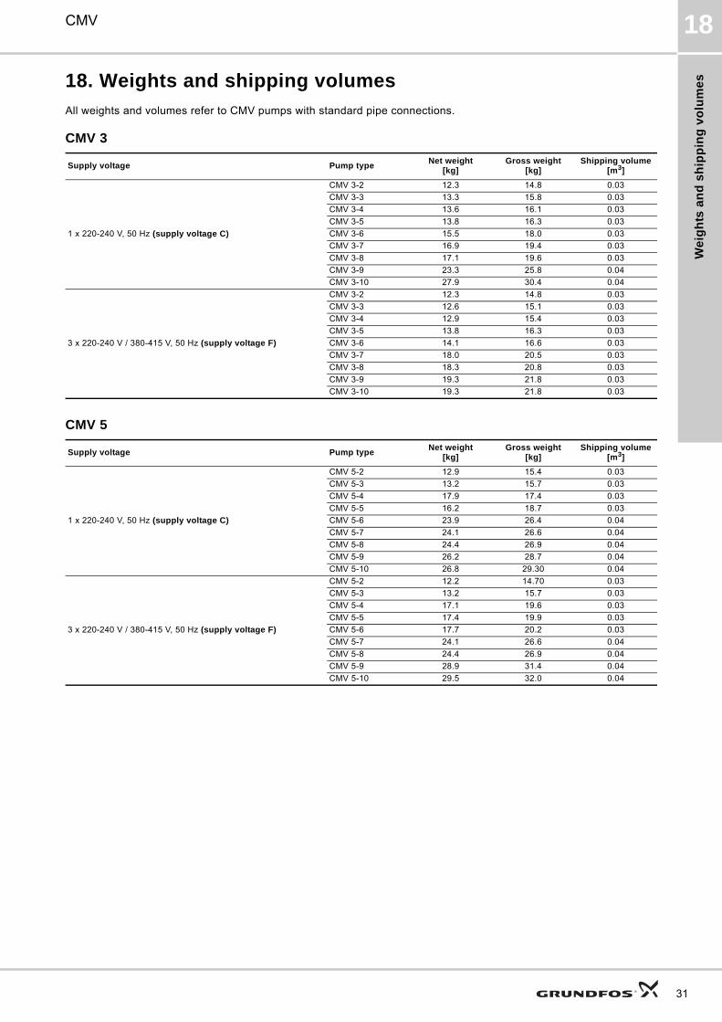
18. Weights and shipping volumes
All weights and volumes refer to CMV pumps with standard pipe connections.
CMV 3
CMV 5
Supply voltage Pump typeNet weight
[kg]Gross weight
[kg]Shipping volume
[m3]
1 x 220-240 V, 50 Hz (supply voltage C)
CMV 3-2 12.3 14.8 0.03
CMV 3-3 13.3 15.8 0.03
CMV 3-4 13.6 16.1 0.03
CMV 3-5 13.8 16.3 0.03
CMV 3-6 15.5 18.0 0.03
CMV 3-7 16.9 19.4 0.03
CMV 3-8 17.1 19.6 0.03
CMV 3-9 23.3 25.8 0.04
CMV 3-10 27.9 30.4 0.04
3 x 220-240 V / 380-415 V, 50 Hz (supply voltage F)
CMV 3-2 12.3 14.8 0.03
CMV 3-3 12.6 15.1 0.03
CMV 3-4 12.9 15.4 0.03
CMV 3-5 13.8 16.3 0.03
CMV 3-6 14.1 16.6 0.03
CMV 3-7 18.0 20.5 0.03
CMV 3-8 18.3 20.8 0.03
CMV 3-9 19.3 21.8 0.03
CMV 3-10 19.3 21.8 0.03
Supply voltage Pump typeNet weight
[kg]Gross weight
[kg]Shipping volume
[m3]
1 x 220-240 V, 50 Hz (supply voltage C)
CMV 5-2 12.9 15.4 0.03
CMV 5-3 13.2 15.7 0.03
CMV 5-4 17.9 17.4 0.03
CMV 5-5 16.2 18.7 0.03
CMV 5-6 23.9 26.4 0.04
CMV 5-7 24.1 26.6 0.04
CMV 5-8 24.4 26.9 0.04
CMV 5-9 26.2 28.7 0.04
CMV 5-10 26.8 29.30 0.04
3 x 220-240 V / 380-415 V, 50 Hz (supply voltage F)
CMV 5-2 12.2 14.70 0.03
CMV 5-3 13.2 15.7 0.03
CMV 5-4 17.1 19.6 0.03
CMV 5-5 17.4 19.9 0.03
CMV 5-6 17.7 20.2 0.03
CMV 5-7 24.1 26.6 0.04
CMV 5-8 24.4 26.9 0.04
CMV 5-9 28.9 31.4 0.04
CMV 5-10 29.5 32.0 0.04
31

Mo
tor d
ata
32
CMV19
19. Motor data
Mains-operated motors, 50 Hz
1 x 220-240 V, 50 Hz (supply voltage C)
3 x 220-240 V / 380-415 V, 50 Hz (supply voltage F)
Frame size P2[kW]
I1/1[A]
Cos φ1/1Istart[A] Speed [min-1]
71B 0.5 3.1 - 2.8 0.97 - 0.99 16 - 15 2730 - 274080A 0.7 4.4 - 4.0 0.99 - 0.99 17 - 16 2720 - 280080B 0.9 5.4 - 5.0 0.98 - 0.98 23 - 22 2750 - 279090SA 1.3 8.4 - 8.0 0.98 - 0.98 29 - 27 2710 - 271090SB 1.9 11.0 - 10.0 0.99 - 0.98 41 - 37 2755 - 2770
Frame size P2[kW]
I1/1[A]
Cos φ1/1Istart[A] Speed [min-1]
71A 0.5 2.0 -2.2 / 1.0 - 1.2 0.83 - 0.75 10 - 12 / 5 - 6 2770 - 2820 71B 0.7 2.8 -3.1 / 1.6 - 1.8 0.82 - 0.82 16 - 19 / 9 - 11 2770 - 2820 80BA 0.9 3.5 - 3.8 / 2.0 - 2.2 0.77 - 0.68 21 - 25 / 12 - 14 2840 - 287080C 1.2 4.8 - 5.2 / 2.8 - 3.0 0.79 - 0.70 39 - 42 / 22 - 24 2820 - 286090SB 1.6 5.6 - 5.4 / 3.3 - 3.0 0.88 - 0.84 46 - 44 / 27 - 25 2880 - 291090SC 2.2 8.2 - 8.5 / 4.7 - 4.9 0.83 - 0.75 68 - 73 / 39 - 42 2900 - 2920

Cu
sto
mis
ati
on
CMV 20
20. Customisation
Although the Grundfos CMV product range offers a number of pumps for different applications, customers require specific pump solutions. Below are the options available for customising the CMV pumps. Contact Grundfos for further information or for requests other than the ones mentioned below.
Motors
Motor with multi-plug connectionMains-operated motors fitted with a Harting® 10-pin multi-plug connection, HAN 10 ES, enable easy connection to the mains.The purpose of a multi-plug connection is to facilitate the electrical installation and service of the pump. The multi-plug functions as a plug-and-pump device.
Fig. 22 Multi-plug logo
Plug connections
Fig. 23 Plug connection from motor
Fig. 24 Plug connection for star connection
Fig. 25 Plug connection for delta connection
Note: Wire bridges for connections are located in the plug.
Motor with anti-condensation heater
Fig. 26 Mains-operated motor with anti-condensation heater
In applications where condensation in the motor may occur, we recommend to install a motor with an anti-condensation heater on the stator coil ends. The heater keeps the motor temperature higher than the ambient temperature and prevents condensation.
TM
02
04
70
07
00
TM
01
87
02
07
00
TM
01
87
03
07
00
6 7 8 9 10
1 2 3 4 5
W2 U2 V2
U1 V1 W1
1 2 3 4 5
6 7 8 9 10
L1 L2 L3
TM
01
87
04
07
00
TM
03
24
40
43
05
1 2 3 4 5
6 7 8 9 10
L1 L2 L3
33

Cu
sto
mis
atio
n
34
CMV20
High humidity may cause condensation in the motor. Slow condensation occurs as a result of a decreasing ambient temperature; rapid condensation occurs as a result of shock cooling caused by direct sunlight followed by rain.In areas with ambient temperatures below 0 °C, it is advisable always to use motors with anti-condensation heater.Note: Rapid condensation is not to be confused with the phenomenon which occurs when the pressure inside the motor is lower than the atmospheric pressure. In such cases, moisture is sucked from the atmosphere into the motor through bearings, housings, etc.
In applications with constant humidity levels above 85 %, the drain holes in the drive-end flange must be open. This changes the enclosure class to IP34.If IP55 protection is required due to operation in dusty environments, it is advisable to install a motor with anti-condensation heater.
Figure 27 shows a typical circuit of a three-phase motor with anti-condensation heater.
Fig. 27 Three-phase motor with anti-condensation heater
Legend
Note: Connect the anti-condensation heater to the power supply so that it is on when the motor is switched off.
The following motor sizes are available with anti-condensation heater:
Motors with PTC sensors
Fig. 28 PTC sensor incorporated in windings
Built-in PTC sensors (thermistors) protect the motor against rapid as well as slow overheating.
We offer built-in PTC sensors to protect the motor.
Mains-operated three-phase motors with supply voltages C and F of 3 kW and up have PTC sensors as standard (UL-approved motors have no internal protection).
Note: PTC sensors must be connected to an external tripping unit.
Protection according to IEC 60034-11:
• TP 211 (slow and rapid overheating).
PTC sensors comply with DIN 44082. Maximum voltage at the terminals, Umax. = 2.5 VDC. All tripping units available for DIN 44082 PTC sensors meet this requirement.
Figure 29 shows a typical circuit of a three-phase motor with PTC sensors.
Fig. 29 Three-phase motor with PTC sensors
TM
03
40
58
14
06
Symbol Designation
K Contactor
M Motor
Motors, 50/60 HzPower of heating unit
[W]
Frame size 1 x 24 V 1 x 190-250 V
71/80
38
23
90 31
100 38
112/132 2 x 38 2 x 38
TM
02
70
38
24
03
TM
00
39
65
14
94
L1 L2 L3 N
K1
M3
N
3UN2 100-0 C
9896A2T2T1
K1
S1
KH2
95A1
H1

Cu
sto
mis
ati
on
CMV 20
Legend
Motors with thermal switches
Fig. 30 Thermal switch incorporated in windings
Built-in thermal switches protect the motor against rapid as well as slow overheating.
We offer mains-operated motors with bimetallic thermal switches in the motor windings.
Mains-operated three-phase motors with supply voltages C and F are available with built-in thermal switches.
Note: Thermal switches must be connected to an external control circuit to protect the motor against slow overheating. The thermal switches require no tripping unit.
Protection according to IEC 60034-11:
• TP 211 (slow and rapid overheating).
As protection against seizure, the motor must be connected to a motor-protective circuit breaker.
Thermal switches tolerate the following maximum loads:
Figure 31 shows a typical circuit of a three-phase motor with built-in bimetallic thermal switches.
Fig. 31 Three-phase motor with thermal switches
Legend
Symbol Designation
S1 On/off switch
K1 Contactor
+T PTC sensor (thermistor) in motor
M Motor
3UN2 100-0 C Tripping unit with automatic resetting
N Amplifier
K Output relay
H1 LED ‘Ready’
H2 LED ‘Tripped’
A1, A2 Connection for control voltage
T1, T2 Connection for PTC sensor loop
TM
02
70
42
24
03
Umax. 250 VAC
IN 1.5 A
Imax. 5.0 A (locked-rotor and breaking current)
TM
00
39
64
14
94
Symbol Designation
S1 On/off switch
K1 Contactor
t° Thermal switch in motor
M Motor
MV Motor-protective circuit breaker
35

Cu
sto
mis
atio
n
36
CMV20
Undersize and oversize motorsThe available motor sizes are shown in 19. Motor data on page 32.
Undersize and oversize motors are defined as the next kW size below or above the fitted standard motor.
Note: The CMV pumps cannot be combined with frame sizes 112 and 132.
It is advisable to use an oversize motor if the operating conditions fall outside the standard conditions.
We especially recommend oversize motors in these cases:
• The pump is installed at an altitude of more than 1000 metres above sea level.
• The viscosity or density of the pumped liquid is higher than that of water.
• The ambient temperature exceeds +55 °C.
It is advisable to use an undersize motor if the operating conditions do not at all reach the standard conditions.
We especially recommend undersize motors in these cases:
• The viscosity or density of the pumped liquid is lower than that of water.
• The duty point of the pump is constant, and the flow rate is significantly lower than the recommended maximum flow rate.
Pumps
Surface treatment
Cleaned and dried pumps
Cleaned and dried pumps are recommended for use in applications involving strict demands on cleanliness and surface quality, such as low content of silicone. Prior to assembly, all pump parts are cleaned in 60 to 70 °C water with a cleaning agent. All pump parts are then thoroughly rinsed in de-ionised water and air-dried. The pump is assembled without any use of silicone lubricants.
Cleaned and dried pumps are not performance-tested.
Alternative colouring
We offer custom-built pumps in any NCS- or RAL-specified colour to suit your requirements.
The used paint is water-based. Painted parts correspond to corrosion class III.
All pump types and sizes are available with alternative colouring.
Customised nameplateWe offer additional customised nameplates attached to the pump:
• A nameplate supplied by you.
• A Grundfos nameplate customised in terms of a specific duty point.
• A Grundfos nameplate with a tag number.
Note: The Grundfos standard nameplate is always fitted to the pump.
Shaft seal arrangementsThe shaft seal is developed with customisation in mind. Depending on media, you may combine the seal faces in any way.
Available stationary seal faces: Q, B.
Available rotating seal faces: Q, V.
Rubber: E and V.
Note: For further details about seal face material codes, see Type key on page 8.
Alternative connection positionsThe pump is available with various connection positions on special request.
Alternative pipe connectionsA wide range of pipe connections are available for the CMV pumps:
• Tri-Clamp®
• DIN, JIS, ANSI flange
• PJE coupling (Victaulic®)
• Whitworth thread Rp
• internal NPT thread.
Fig. 32 Pipe connections
TM
05
07
81
15
11

Ac
ce
ss
ori
es
CMV 21
21. Accessories
Pipework connectionsVarious sets of flanges and couplings are available for pipework connection.
Distance pieceThe distance piece is intended for mounting on the discharge port in order to improve the accessibility when connecting the pump to the piping system.
The distance piece is made of brass.
Flange sets for CMV (DIN/ANSI/JIS)All materials in contact with the pumped liquid are made of stainless steel, EN 1.4408/AISI 316.
* Length from outer edge of flange to pump suction or discharge port.
Counter flanges for CMVCounter flanges for CMV pumps are made of cast iron, EN-GJL-200.
A counter-flange set consists of one counter flange, one gasket, bolts and nuts.
Distance piece Pump typePipework
connectionPump thread
Product number
TM
04
58
00
40
09
CMV 3CMV 5
1" R 96587201
Flange Pump typePipework
connectionPump thread
L* [mm]Product numberFlange fitted to
pump inletFlange fitted to
pump outlet
TM
04
38
67
03
09
CMV 3
DN 32
Rp
49.0 78.0
96904693
NPT 96904705
CMV 5
Rp 96904696
NPT 96904708
Counter flange Pump type Description Rated pressurePipework
connectionProduct number
TM
03
04
00
37
05
CMV 3-ACMV 5-A
Threaded 16 bar, EN 1092-2 Rp 1 1/4 00419901
For welding 25 bar, EN 1092-2 32 mm, nominal 00419902
ø19
ø140ø100ø78
37

Ac
ce
ss
orie
s
38
CMV21
PJE/Victaulic® connections for CMV
* Length from outer edge of PJE connection to pump suction or discharge port.
Coupling, pipe stub and gasket for PJE connections
Parts in contact with the pumped liquid are made of stainless steel, EN 1.4401/AISI 316, and rubber.
A PJE coupling set consists of two coupling halves (Victaulic®, type 77), one gasket, one pipe stub (for welding or threaded), bolts and nuts.
* For discharge port. Note: Only one coupling set is required for the discharge port.
** For suction port.
Tri-Clamp® connections for CMV
* Length from outer edge of Tri-Clamp® connection to pump suction or discharge port.
PJE connection Pump typePump thread
D [mm] L* [mm]Product number
TM
04
38
65
03
09
CMV 3Rp
33.7 48.596904694
NPT 96904706
CMV 5Rp
33.7/42.4 48.596904697
NPT 96904709
Coupling and pipe stub Pump type Pipe stubPipework
connectionRubber parts
Number of coupling sets
required
Product number
TM
00
38
08
10
94
CMV 3CMV 5*
Threaded R 1EPDM 2 97575245
FKM 2 97575246
For welding DN 25EPDM 2 97575247
FKM 2 97575248
CMV 5**
Threaded R 1 1/4EPDM 1 00419911
FKM 1 00419905
For welding DN 32EPDM 1 00419912
FKM 1 00419904
Tri-Clamp® Pump type Pump threadD
[mm]L*
[mm]Product number
TM
04
38
66
03
09
CMV 3
Rp
50.4 40.3
96904695
NPT 96904707
CMV 5
Rp
50.4 35.3
96904698
NPT 96904710

Ac
ce
ss
ori
es
CMV 21
Clamping ring, pipe stub and gasket for Tri-Clamp® connections
The clamping ring is made of stainless steel, EN 1.4301/AISI 304.
The pipe stub is made of stainless steel, EN 1.4401/AISI 316.
The gasket is made of PTFE or EPDM.
Clamping ring Pipe stub Gasket
TM
03
46
45
24
06
TM
03
46
46
24
06
TM
03
46
47
24
06
Pump typeNominal diameter
[mm]A
[mm]B
[mm]A
[mm]B
[mm]C
[mm]D
[mm]A
[mm]B
[mm]
CMV 3, 5 38.0 92.0 59.5 21.5 50.5 35.6 38.6 35.3 50.5
Pump typePipework
connectionConnection material Gasket
Pressure[bar]
Number of coupling sets
required
Product number
CMV 3, 5 DN 32 Stainless steelEPDM
162 96515374
PTFE 2 96515375
39

Ac
ce
ss
orie
s
40
CMV21
MP 204 motor protector
Fig. 33 MP 204
The MP 204 is an electronic motor protector and data collecting unit. Apart from protecting the motor, it can also send information to a control unit via GENIbus, like for instance:
• trip
• warning
• energy consumption
• input power
• motor temperature.
The MP 204 protects the motor primarily by measuring the motor current by means of a true RMS measurement.
The pump is protected secondarily by measuring the temperature with a Tempcon sensor, a Pt100/Pt1000 sensor and a PTC sensor/thermal switch.
The MP 204 is designed for single- and three-phase motors.
Note: The MP 204 must not be used together with frequency converters.
Features
• Phase-sequence monitoring
• indication of current or temperature
• input for PTC sensor/thermal switch
• indication of temperature in °C or °F
• 4-digit, 7-segment display
• setting and status reading with the Grundfos R100 remote control
• setting and status reading via the Grundfos GENIbus fieldbus.
Tripping conditions
• Overload
• underload (dry running)
• temperature
• missing phase
• phase sequence
• overvoltage
• undervoltage
• power factor (cos φ)
• current unbalance.
Warnings
• Overload
• underload
• temperature
• overvoltage
• undervoltage
• power factor (cos φ)
• run capacitor (single-phase operation)
• starting capacitor (single-phase operation)
• loss of communication in network
• harmonic distortion.
Learning function
• Phase sequence (three-phase operation)
• run capacitor (single-phase operation)
• starting capacitor (single-phase operation)
• identification and measurement of Pt100/Pt1000 sensor circuit.
Product number
Cover for CMV motorThe cover protects the motor from ingress of liquid, especially if the pump is installed in a vertically tilted position with the motor end pointing upwards.
Product number
Angled cable gland
Fig. 34 Angled cable gland with O-ring and lock nut
TM
03
14
71
22
05
Description Product number
MP 204 motor protector 96079927
Description Product number
Cover for CMV motors, frame sizes 71 and 80 97528743
TM
05
07
29
14
11
Description Product number
Angled cable gland with O-ring and lock nut 97842998
Fu
rth
er
pro
du
ct
do
cu
me
nta
tio
n
CMV 22
22. Further product documentation
WebCAPSWebCAPS is a Web-based Computer Aided Product Selection program available on www.grundfos.com.
WebCAPS contains detailed information on more than 220,000 Grundfos products in more than 30 languages.
Information in WebCAPS is divided into six sections:
• Catalogue
• Literature
• Service
• Sizing
• Replacement
• CAD drawings.
Catalogue
Based on fields of application and pump types, this section contains the following:• technical data• curves (QH, Eta, P1, P2, etc.) which can be adapted to the
density and viscosity of the pumped liquid and show the number of pumps in operation
• product photos• dimensional drawings• wiring diagrams• quotation texts, etc.
Literature
This section contains all the latest documents of a given pump, such as• data booklets• installation and operating instructions• service documentation, such as Service kit catalogue and
Service kit instructions• quick guides• product brochures.
Service
This section contains an easy-to-use interactive service catalogue. Here you can find and identify service parts of both existing and discontinued Grundfos pumps.Furthermore, the section contains service videos showing you how to replace service parts.
41

Fu
rthe
r pro
du
ct d
oc
um
en
tatio
n
42
CMV22
WinCAPS
Fig. 35 WinCAPS CD-ROM
WinCAPS is a Windows-based Computer Aided Product Selection program containing detailed information on more than 220,000 Grundfos products in more than 30 languages.
The program contains the same features and functions as WebCAPS, but is an ideal solution if no internet connection is available.
WinCAPS is available on CD-ROM and updated once a year.
Sizing
This section is based on different fields of application and installation examples and gives easy step-by-step instructions in how to size a product:• Select the most suitable and efficient pump for your installation• Carry out advanced calculations based on energy
consumption, payback periods, load profiles, life cycle costs, etc.
• Analyse your selected pump via the built-in life cycle cost tool• Determine the flow velocity in wastewater applications, etc.
Replacement
In this section you find a guide to selecting and comparing replacement data of an installed pump in order to replace the pump with a more efficient Grundfos pump. The section contains replacement data of a wide range of pumps produced by other manufacturers than Grundfos.
Based on an easy step-by-step guide, you can compare Grundfos pumps with the one you have installed on your site. When you have specified the installed pump, the guide will suggest a number of Grundfos pumps which can improve both comfort and efficiency.
CAD drawings
In this section, it is possible to download 2-dimensional (2D) and 3-dimensional (3D) CAD drawings of most Grundfos pumps.
These formats are available in WebCAPS:
2-dimensional drawings:• .dxf, wireframe drawings• .dwg, wireframe drawings.
3-dimensional drawings:• .dwg, wireframe drawings (without surfaces)• .stp, solid drawings (with surfaces)• .eprt, E-drawings.
0 1
Subject to alterations.

43

GRUNDFOS A/S . DK-8850 Bjerringbro . DenmarkTelephone: +45 87 50 14 00www.grundfos.com
The name Grundfos, the Grundfos logo, and the payoff Be–Think–Innovate are registrated trademarks owned by Grundfos Management A/S or Grundfos A/S, Denmark. All rights reserved worldwide.
Being responsible is our foundationThinking ahead makes it possible
Innovation is the essence
97942071 0611 GBRepl. 97942071 0511
ECM: 1076991