gps moving vehicle experiment - nasa · gps moving vehicle experiment o. j. oaks ... (saias) gps...
TRANSCRIPT

I,
/
GPS MOVING VEHICLE EXPERIMENT
O. J. Oaks
Wilson Reid
Naval Research Laboratory
Washington, D.C. 20375-5000
Hugh Warren
SFA, Inc.
James Wright
Christopher Duffey
Charles Williams
Computer Sciences Raytheon
Tom Zeh
Naval Undersea Warfare Center
Detachment AUTEC
James Buisson
Antoine Enterprises
Abstract
The Naval Research Laboratory (NRL ), in the development of timing systems for remote locations,had a technical requirement for a Y code (SAIAS) GPS precise time transfer receiver (TTR) whichcould be used both in a stationary mode or mobile mode. A contract was awarded to the StanfordTelecommunication Corporation (STEL) to build such a device. The Eastern Range (ER) also had
a requirement for such a receiver and entered into the contract with NRL for the procurement ofadditional receivers. The Moving Vehicle Experiment (MVE) described in this paper is the Jlrst in
situ t_ of the STEL Model 5401C Time Transfer System in both stationary and mobile operation.The primary objective of the MVE was to test the timing accuracy of the newly developed GPS
TTR aboard a moving vessel. To accomplish this objective, a joint experiment was performed with
personnel from NRL and the ER at the Atlantic Undersea Test and Evaluation Center (AUTEC)Range at Andros Island. This range is under the direction of the Naval Undersea Warfare Center(NUWC), Newport, Rhode Island. The test was conducted through the West Palm Beach OVPB)Detachment of the NUWC.
Results and discussion of the test are presented in this paper.
BACKGROUND
The U.S. Naval Research Laboratory (NRL), in the development of timing systems for remotelocations, had a technical requirement for a Y code (SMAS) GPS precise time transfer receiver
(TTR) which could be used both in a stationary mode or mobile mode. A contract was awardedto the Stanford Telecommunication Corporation (STEL) to build such a device. The EasternRange (ER) also had a requirement for such a receiver and entered into the contract withNRL for the procurement of additional receivers. The Moving Vehicle Experiment (MVE)described in this paper is the first in situ test of the STEL Model 5401C Time Transfer Systemin both stationary and mobile operation.
397
https://ntrs.nasa.gov/search.jsp?R=19960042645 2019-02-03T10:22:23+00:00Z

OBJECTIVE
The primary objective of the MVE was to test the timing accuracy of the newly developed GPSTTR aboard a moving vessel. To accomplish this objective, a joint experiment was performedwith personnel from NRL and the ER at the Atlantic Undersea Test and Evaluation Center(AUTEC) Test Range at Andros Island. This range is under the direction of the Naval UnderseaWarfare Center (NUWC), Newport, Rhode Island. The test was conducted through the WestPalm Beach CWPB) Detachment of the NUWC.
PARTICIPANTS
The following personnel and their organizations participated in this experiment:
Name Organization Title
O. J. Oaks
James WrightChristopher DuffeyChauncey DunnCharles Williams
Hugh WarrenWilson Reid
Ernie MoodyJack CecilTom Zeh
Dave CooneyJeff ByrneLinda ToughLaurie RobinsonEd CoteGerald Phifer
Rick BeasleyChris HollyMike BoyleJames Buisson
Naval Research LaboratoryComputer Sciences RaytheonComputer Sciences RaytheonComputer Sciences Raytheon
Computer Sciences RaytheonSFA, Inc.
Naval Research LaboratoryNUWC, NewportAUTEC WPBAUTEC WPBAUTEC Andros IslandAUTEC WPBAUTEC Andros IslandAUTEC Andros IslandAUTEC Andros IslandAUTEC Andros IslandAUTEC Andros IslandAUTEC Andros IslandAUTEC Andros Island
Antoine Enterprises
Code 8153 , Head
Timing Systems, LeaderTiming Systems EngineerTiming Systems O&M, Mgr.Timing Systems O&M, Tech.EngineerCode 8153
Code 3891, HeadCode 3814, Head
Program ManagerProgram Test ConductorEngineerRange User CoordinatorData Analysis GroupLaunch Recovery Sys. Eng.Security EngineerR/V Ranger, CaptainR/V Ranger, 1st MateR/V Ranger, 2nd MateConsultant to SFA, Inc.
METHODOLOGY AND IMPLEMENTATION
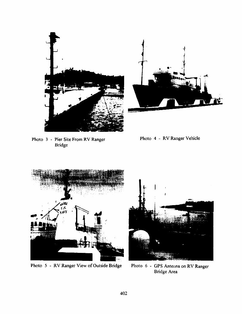
To begin the MVE, tests were first conducted in a stationary mode at a known location atthe AUTEC pier to assure calibration and initial data validation. The GPS TTR antenna was
located directly above a Defense Mapping Agency (DMA) benchmark survey point (Photo 1).Two receivers were used and configured as shown in Figure 1 and Photo 2. The GPS TTR(S/N15) was later removed from the shed on the pier (Photo 3) and used aboard the AUTEC
vessel, R/V Ranger. The ship is shown in Photos 4 and 5. While the test was performed onthe vessel, the GPS TTR antenna was mounted on the rail adjacent to the bridge of the ship,as shown in Photo 6.
The atomic frequency standards used in the experiment were supplied by Computer SciencesRaytheon (CSR), who is the ER contractor, from their Cape Canaveral Range OperationControl Center (ROCC). The HP 5061A cesium frequency standard (S/N 2383) was maintained
398

in the ROCC laboratory prior to the MVE. Timing data relative to UTC(USNO) were recordedfor ten days prior to its being transported. The 5061A was equipped with an external batterysupply, and continuous operation of the clock was maintained throughout the test. The testincluded a 2-hour drive from Cape Canaveral to West Palm Beach, a 45-minute plane ridefrom WPB to the AUTEC Andros Island Site, and movement from the pier shed to the ship
(Photos 7 and 8).
As shown in Figure 1, both STEL GPS TTRs were driven by the 5 MHz signal from theHP5061A (S/N 2383) frequency standard, to assure calibration of the complete system beforeremoving TTR (S/N 15) to the ship. Figures 2 and 3 depict the equipment configuration next
employed. Each of the TTRs was driven by independent frequency standards. The HP5061Afrequency standard supplied 5 MHz to TTR (S/N 15), and the FTS 4050 (S/N A167) cesiumfrequency standard supplied the required 5 MHz to TTR (S/N 20).
The FTS 4050 cesium frequency standard was shipped to AUTEC Andros, with no batterysupply, in a powered-down condition. Before being connected to the GPS TTR, its phase wasadjusted to within 1 nanosecond of that of the HP5061A. This was done so that at the end ofthe MVE onboard test, the HP frequency standard could again be compared to the FTS 4050to assure continuous operation of the HP 5061A clock during the test. The two clocks wereoperated during a 24-hour period to determine the frequency offset between the two clocks
prior to the transport of the HP clock onboard the R/V Ranger.
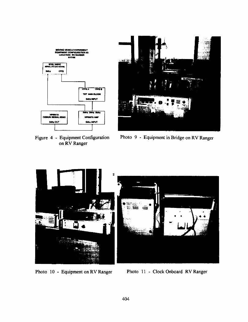
Figure 4 shows the equipment configuration for the STEL TTR S/N 15 driven by the HP5061Aas it was used during the MVE sea trial portion of the test. Photos 9, 10, and 11 show theequipment as it was configured on the bridge of the Ranger.
The AUTEC Andros Test Range was chosen because the Navy routinely performs tests usingships such as the Ranger, and NRL could easily procure space and time as a secondaryexperimenter at a minimum cost to conduct the MVE. The AUTEC Range performs both asurface radar tracking and in-water precise tracking of the Navy vessels. The precise in-watersystem uses hydrophone pingers. All tracking data of the ship during the MVE were suppliedto the experimenters at the conclusion of the test.
RESULTS
Data obtained on 14 May 1995, with the equipment configured as shown in Figure 1, arepresented in Figures 5 and 6. The plots show the phase difference between the HP5061Aclock and UTC(USNO), as measured through GPS using the two TTRs. The 9-nanosecond
quantization of the receiver output can easily be seen in the graph. Essentially no phaseoffset exists between the two receivers, and each receiver realized a peak-to-peak variance of
approximately 40 nanoseconds, with an rms deviation of 11.8 nanoseconds and 12.3 nanosecondsrespectively. This is considered excellent performance for receivers on a stationary platform.
The tests were repeated on 15 May 1995 in the same configuration, and the essentially identicalresults are presented in Figures 7 and 8. The rms deviation was 11.9 nanoseconds for TrR(S/N 20) and 10.2 nanoseconds for TTR (S/N 15).
The receivers were then configured as shown in Figures 2 and 3, that is, with each receiver onits own frequency standard. TI'R (S/N15) was driven by the HP clock, while TTR (S/N 20)was now driven by the FTS clock.
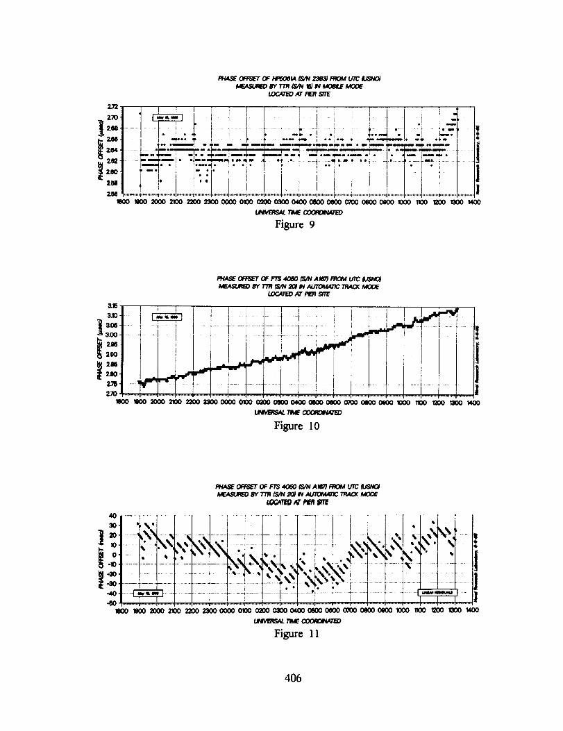
Results obtained during the period of 15 to 16 May are presented in Figures 9 and 10.
399

Immediately evident is a frequency offset of the FTS clock from the HP dock, as shown inFigure 10. The larger phase offset in Figure 10 can then be attributable to the accumulatedphase due to the frequency offset of the FTS clock, since the two clocks were synchronized on12 May. Figure 11 presents residuals to a linear fit using the data from Figure 10. The rmsdeviation of each receiver during this period was 15.3 nanoseconds for TrR (S/N 15) and 15.3
nanoseconds for TrR (S/N 20).
The final results were obtained during the sea trials after TrR (S/N 15) and the HP clock hadbeen placed aboard the RN Ranger. Figure 12 is the data obtained with Receiver 20 at theshed on the pier. The rms deviation of this data set was 10.7 nanoseconds. Figure 13 presentsresults obtained from the sea trials. During this period, the speed of the ship changed fromstationary to about 10 knots, with the heading varying 360 degrees. Because of the nature ofthe primary experiments, sudden shocks and vibrations were received by the test equipment. Ascan be seen in Figure 13, the results were excellent during the entire trial. The rms deviationduring the sea trial was calculated to be 14.8 nanoseconds.
CONCLUSIONS
Figures 14 and 15 are a succinct summary to the MVE. Depicted on Figure 14 is the measuredoffset of the HI' 5061A clock from UTC(USNO) for the entire period of the experiment.Figure 15 presents the residuals to a linear fit of the data and the accompanying statistics.Data for the first ten days were taken at the ROCC lab prior to deployment to AUTEC. Datafor the next six days were obtained at the pier in the AUTEC Andros Range. Data for the17th day were obtained during the sea trials. The final data points were obtained after theclock had been transported back to its original location at the ROCC. The overall closure hasan rms deviation of 13 nanoseconds using all the data collected. This is excellent performanceand is well within the system specification.
400

I1
Photo 1 - Initial Set Up on Pier
(2 antennas)
Photo 2 - Equipment in Pier Facility
MOVING VEHICLE EXPERIMENT
EQUIPMENT CONFIGURATION #1
LOCATION: PIER SITE
5/13/95 - 6/16/95
STEL 6401C
SERIAL #15
5Mhz 1PPS
HPE0eIA
CESIUM SERIAL #2383
5Mhz OUT
Figure 1
I I1PPS A 1PPS B
TST 6489 CLOCK
5Mhz INPUT
ill5Mhz 5Mhz 5Mhz
HPS087A AMP
5Mhz INPUT
]Initial Equipment Configuration Pier Site
8TEL 6401C
SERIAL #20
1PPS 6Mhz
401
i
Photo 3 - Pier Site From RV Ranger
Bridge
Photo 4 - RV Ranger Vehicle
Photo 5 - RV Ranger View of Outside Bridge Photo 6 - GPS Ante_ma on RV Ranger
Bridge Area
402

Photo 7 - CesiumClockonPier Photo 8 - Cesium Clock in Flight
N_m
Wm1_ #2
l ITIIL 14_C ]
inu¢ ell ¢Jo MOU)
Met IPPII
¢IUII_MI IXERUU. INI_IU
6MI_ OUT
I
I 11_11A 1111_ B
111T 1411 _1.1_1(
5111m _
_I_T.....HP(INTA AMP
6&t,I INPUT
I 1
Figure 2 - Equipment Configurationat Pier Site Prior to
Shipboard
MOVING VIEHICUE IUCPWqlMIU_
_ ¢_qGuFU_TION 12
LOCATION: _ 8/TIE
WlC_NI - Ib't 7AI4
I
IIIM, m INII_
FT8 40_
CESIUm _JVAL M,t(ff
6Mr_ OUT
[ ]
11RA AMP
I R IHI_¢ 1
Figure 3 - Final Equipment Configurationat Pier Site
403
N W laulmmlllttW I'llo_ I1_
LOGATION: RV
_1
- Immu
5MIz OUT
L
i1_Wlz al_e 6M_ r
WA NIP
_lhz NPUT
Figure 4 - Equipment Configuration
on RV Ranger
Photo
m
9 - Equipment in Bridge on RV Ranger
Photo 10 - Equipment on RV Ranger Photo 11 - Clock Onboard RV Ranger
404

• oi......... i ......... ,......... , ......... ;...... -
_ _ _ _ _ _-e,i e,i
....o -°
...... a......... _......... i......... _......... I
405
2.T_
2.70.
268,
2.(M.
_ 2.00,
2.M
2M
LOCATe) JO"PI_ ,gTE
1000 110020002100 22(X) 2300 O0(X) 01(X) O_C)O0_CX) 04000600 OeCX)0700 OeO0 oeO0 1000
_ 7'J_ c_
Figure 9
I f i i I i ! J _ 1 Y
' tt I_ I_ I , i ! , ..... -
...............................n * • i ........... 4 .............. _ i "**" i *i!_........ "_ ...... !.... _r '! _**_ ""f!! " ............. " I
"'** _" 1 ! " _' _' "*" " , **r*- "_ '_"_"_" "_" "T" 1! _** ,ml o _oo m _eim m i*_*,_m_.n * lln_luom_loni_ _m I
......... _.. *_--* _-,_--__ .... _..-- _ -- ........ ,...m.--.,----,_ 1.......
......._'"""I "_ "---_'--"_*"-" .,4......._,................... i.........._.- * .._ . . _..........'_--*._ .......I'='='_, ° • i F'"*M" !" " " i' T I I "'_" ; i , _ • I "| I II
_' _"'I ; I-- • * i ; .... '_ [ i , |
41'''] '• I IL,],, 1..........I.................................................................. _....................................................... I...........I...........i""'"'"' '"""'"''_ .......................................
1100 _00 1300 1400
R_IAS_ 0FFSET OF FT_ 40_0 _N A MT) FRt_ U'/C_SNt_MF.AStX_EDtr_TT_ _/N 20) W _ 7RAC_ MOOE
_ AT PIERS/TE
3"151 I I I ] _ l I I I i ;, [ I I I -" ,,,,,,_ r
_.oo] ,l_m .......i, i ........,,....................................................................I , ..... ] .... I ....................'..............+'......f __-' _..... ' ...... I
iI
Ii00 1000 2100 2200 13000000 0100 l_00 0100 0400 0600 0400 0700 OlO00_)O 1000 1100 _00 _ 1400
I,IVl4ttS_ 71M_ _
Figure 10
R_t4$E OFFSET OF r/S 4060 _S/NA _7) _;0_ t.n'CtUSN0_
_EASU_D 8Y _'/R_4 20)_ _ TRACX MOD_
Figure 11
406

|1
I
":-al,:I' J_• I,, I:_
• "l I i
" * * | _ .lu
!...............,!!iiiiiI°o•, . ..... ,e
_ 3SVH_
! | f,!
llut I
|,el 10 il,i / . . _
o_
_* 1 " o
i- • i!il
ill
| <-!'_................................,..... "Ill
(_llu) 1.qldlO livid
407
Questions and Answers
HAROLD CHADSEY (USNO): Chris and I had talked earlier about this, this is a loaded
question for him. When I gave my presentation, I said it was part of a much larger report. It
turns out that Chris's report is the final section that I was unable to do. The question is for
you: What type of processing did you do to get such smooth results; because, if you do it out
on six-second data points, the six-second data points will vary by more than 50 nanoseconds?
When you do your moving position, what was your offset standing still?
The receivers that I was using had offsets in latitude and longitude by approximately a meter;
and the altitude was approximately two to three meters, on average, but would exceed 20
meters on the six-second level. I'm just wondering, what did you see?
CHRISTOPHER S. DUFFEY (COMPUTER SCIENCES RAYTHEON): We didn't -
there's no processing done on this data to smooth it out or correct any - other than removal
of the frequency drift in that one cesium. In fact, we were quite surprised that the initial
results came up on the prediction for cesium because it's so close. Maybe we've got a couplegood receivers.
I haven't shown - we ditched the difference data of the lat, long and altitude of the AUTEC-
provided coordinates, they had finger data on our vessels during the whole time. And we
haven't quite finished crunching it all. But you do see some small offsets, less than 10 meters,for sure, and probably rms-positioning errors of around six meters difference.
HAROLD CHADSEY (USNO): Your results are obviously not six-second data points. Howdid you get the data points?
CHRISTOPHER S. DUFFEY (COMPUTER SCIENCES RAYTHEON): All of those
data points were out of RS-232 port of the receiver. And, I look back on it and they wereone-minute points.
HAROLD CHADSEY (USNO): One-minute averages?
CHRISTOPHER S. DUFFEY (COMPUTER SCIENCES RAYTHEON): Yes. The
receiver has a Kalman filter in it. So unless you disable that, you are going to get somzsmoothing in the operation.
HAROLD CHADSEY (USNO): Okay, that would be the difference between ours; because,I wasn't using the internal Kalman filtering; we avoided that and wired around it.
408