conceptual design of a moving belt radiator shuttle ... · nasa contractor report 185169 conceptual...
TRANSCRIPT
NASA Contractor Report 185169
Conceptual Design of a Moving Belt RadiatorShuttle-Attached Experiment
Final Report
Jerry L. Aguilar
Arthur D. Little, Inc.
June 1990
Prepared forLewis Research Center
Under Contract NAS3-25356
NASANational Aeronautics and
Space Administration
Arldur D Litlde
https://ntrs.nasa.gov/search.jsp?R=19900014158 2018-06-23T05:47:27+00:00Z

TABLE OF CONTENTS
1.0 SUMMARY ...................................................................................................................... 1
2.0 BACKGROUND ................................................................................................................ 12.1 MOVING BELT RADIATOR SYSTEM OPTIONS ...................................................... 32.2 SUMMARY OF PREVIOUS WORK ........................................................................... 4
3.0 OBJECTIVES AND SCOPE ............................................................................................. 53.1 MBR PROGRAM ...................................................................................................... 63.2 SHUTTLE EXPERIMENT .......................................................................................... 7
4.0 ANALYSIS ........................................................................................................................ 84.1 DYNAMIC ANALYSIS ................................................................................................ 84.2 THERMAL ANALYS LS ............................................................................................... 9
5.05.15.25.35.45.55.65.75.85.95.10
CONCEPTUAL DESIGN AND DESIGN CONSIDERATIONS ......................................... 13CARRIER AND EXPERIMENT MOUNTING ............................................................. 15THERMAL SYSTEM DESIGN ................................................................................... 17MAIN DRIVE SYSTEM .............................................................................................. 18DEPLOYM ENT/RETRACTION SYSTEM .................................................................. 19PERTURBATION SYSTEM ....................................................................................... 19BELT SELECTION ..................................................................................................... 20WORKING FLUID SELECTION ................................................................................. 21WORKING FLUID CONTAINMENT ........................................................................... 22REQUIRED MEASUREMENTS AND DATA HANDLING .......................................... 23GROUND SUPPORT ................................................................................................. 25
6.0 PAYLOAD CARRIERS ..................................................................................................... 266.1 POSSIBLE CARRIERS .............................................................................................. 266.2 SELECTED CARRIER ............................................................................................... 276.3 OPTIONAL CARRIER ................................................................................................ 27
7.0 REQUIREMENTS OF SHUTTLE ..................................................................................... 287.1 POWER .................................................................................................................... 287.2 ORBIT ........................................................................................................................ 287.3 TIME REQUIREMEHTS ............................................................................................ 297.4 MASS ESTIMATE ..................................................................................................... 297.5 VOLUME ESTIMATF ................................................................................................. 307.6 MISSION SPECIALIST INTERACTION ..................................................................... 307.7 EVA AND RMS REQUIREMENTS ............................................................................ 31
8.0 SAFETY ISSUES ............................................................................................................ 318.1 WORKING FLUID CONTAINMENT ........................................................................... 318.2 OPERATING CONDITIONS ...................................................................................... 328.3 BACKUP SYSTEMS .................................................................................................. 338.4 POSSIBLE MALFUNCTIONS AND RESULTS .......................................................... 33
9.0 TEST PLAN ..................................................................................................................... 339.1 REQUIRED GROUND TESTING .............................................................................. 339.2 DEPLOYMENT ......................................................................................................... 359.3 DYNAMIC TESTING IN SPACE ................................................................................ 359.4 THERMAL TESTING IN SPACE ............................................................................... 359.5 RETRACTION AND STORAGE ................................................................................ 38
10.0 PROGRAM PLAN ........................................................................................................... 3810.1 INTEGRATION RECUIREMENTS ............................................................................ 3810.2 REQUIRED TASKS AND MANPOWER ESTIMATES ............................................... 3810.3 SCHEDULE .............................................................................................................. 39
11.0 REFERENCES ................................................................................................................ 42
PRECEDING PAGE BLANK NOT FILMED

1.0 SUMMARY
The Moving Belt Radiator (MBR) In-Space Experiment is designed to demonstrate the dynamic,
the thermal, and the interface heat exchanger (IHX) sealing performance of a scaled down version
of a MBR system. The features of the MBR include a self-deploying radiator with no structural
supports, an efficient heat exchanger, potential for up to 200 MW of power dissipation, and mass
of one third to one fifth of current heat pipe technology.
The proposed testing will be divided into three stages - steady state, dynamic, and thermal test
phases - in addition to deployment and retraction sequences. The experiment will operate relatively
independently with the only interaction between crew and experiment being the manual switching
of the experiment from one phase to the next. During the dynamic testing, linear perturbations will
be imposed on the IHX in order to verify the damping of the belt and the effects on the belt motion.
The experiment is expected to verify the predicted dynamic characteristics of a MBR in a
microgravity environment, provide a basis for refining a computer model of the dynamics, verify
the predicted thermal performance of the MBR in a space environment, and demonstrate the
performance of the IHX seals in a vacuum environment. Once all of these characteristics are
demonstrated and models refined, then larger MBR systems can be designed with increasedconfidence.
The apparatus will contain eilght subsystems:
• Main drive system for driving the belt during testing and deployment;
• Deployment/Retraction system for storing the belt during ascent, descent and non-use
periods, and for use during the deployment and retraction sequences;
• Perturbation system wl" ich will provide linear accelerations to the experiment simulating
a docking type maneuver;
• Interface Heat Exchanger which will transfer the heat to the belt from the source;
• Fluid Storage and Transport system, used to store the working fluid during non thermal
test periods and to tran_,port the fluid to the IHX prior to thermal testing;
• Control system used to :)perate the experiment and to maintain proper tracking of the belt;
• Data and Communications systems which will provide for the recording of data and the
communication of instructions to the experiment.
2.0 BACKGROUND
As part of ongoing work with NASA Lewis Research Center since 1982, Arthur D. Little, Inc.
(ADL) has been developing the Moving Belt Radiator (MBR) System concept for use on spacecraft.
In this concept, shown in Figure 1, a belt is drawn through an interface heat exchanger (IHX)
containing a low vapor pressure working fluid which functions as the heat sink for the power
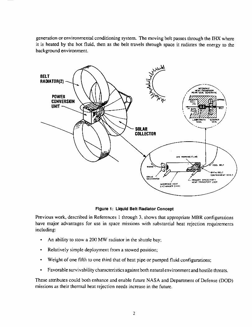
generationorenvironmentalconditioningsystem.Themovingbelt passesthroughtheIHX whereit is heatedby the hot fluid, then asthe belt travels through spaceit radiatesthe energyto thebackgroundenvironment.
BELTRADIATOR(2)
POWERCONVERSIONUNIT
SOLARCOLLECTOR
Figure 1: Liquid Belt Radiator Concept
Previous work, described in References 1 through 3, shows that appropriate MBR configurations
have major advantages for use in space missions with substantial heat rejection requirements
including:
• An ability to stow a 200 MW radiator in the shuttle bay;
• Relatively simple deployment from a stowed position;
• Weight of one fifth to one third that of heat pipe or pumped fluid configurations;
• Favorable survivability characteristics against both natural environment and hostile threats.
These attributes could both enhance and enable future NASA and Department of Defense (DOD)
missions as their thermal heat rejection needs increase in the future.
2.1 MOVING BELT RADIATOR SYSTEM OPTIONS
This effort initially focussed on liquid belt radiators (LBR) wherein a meniscus of the IHX fluid is
formed on a mesh structure, the. belt. This concept resulted in excellent heat transfer characteristics
in the IHX and could take adwmtage of the heat of fusion of the IHX liquid (tin, lithium, etc.). A
second option is the solid belt radiator (SBR) concept which consists of a flat solid belt being drawn
through a heat exchanger, the heat exchanger being either a liquid bath or a solid to solid contact.
The SBR has the advantage over the LBR in that no free liquid surface is exposed to space. Recently,
increased attention has been focussed on a unique hybrid belt radiator (HBR) design which retains
the excellent heat transfer characteristics of the LBR in the IHX and also does not result in a free
liquid surface exposed to space while increasing the thermal capacity over that of a SBR concept.
The HBR consists of a phase change material that is encased within the belt. Again the belt is drawn
through a heat exchanger, liquid bath or solid-solid contact, then radiates the thermal energy to
space. The three concepts, LBR, SBR, and HBR, are collectively referred to as the MBR system.
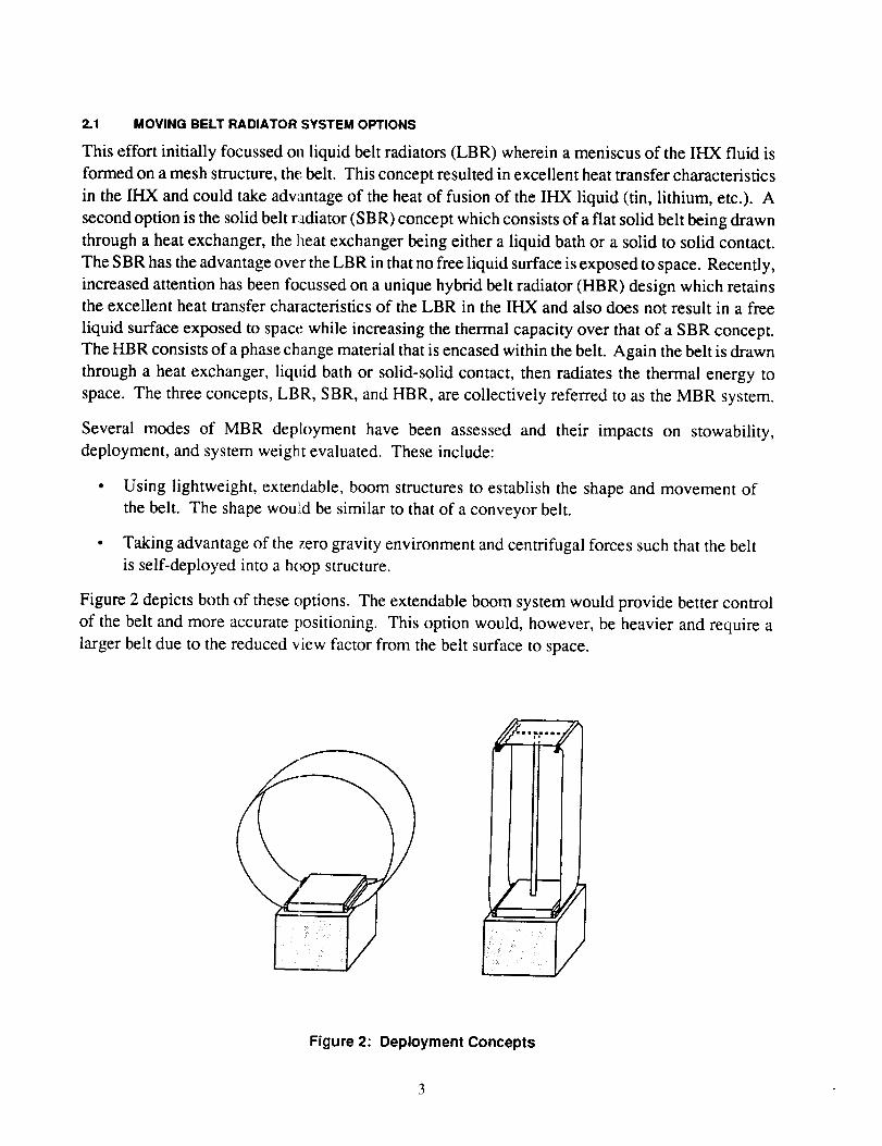
Several modes of MBR deployment have been assessed and their impacts on stowability,
deployment, and system weight evaluated. These include:
• Using lightweight, extendable, boom structures to establish the shape and movement of
the belt. The shape would be similar to that of a conveyor belt.
• Taking advantage of the zero gravity environment and centrifugal forces such that the belt
is self-deployed into a hoop structure.
Figure 2 depicts both of these options. The extendable boom system would provide better control
of the belt and more accurate positioning. This option would, however, be heavier and require a
larger belt due to the reduced view factor from the belt surface to space.
<J J
/
Figure 2: Deployment Concepts
The alternative, and preferred, configuration does not use any deployment structure and is predicted
to produce a circular shape due to the centrifugal forces. If a circular shape is formed then the best
view factoris also achieved. Both of these advantages decrease the system weight. The disadvantage
to the self-deployed configuration is that the dynamics are very difficult to predict and testing must
be conducted in a reduced gravity and vacuum environment.
2.2 SUMMARY OF PREVIOUS WORK
Past efforts have included:
• Development of benchtop experiments to assess the heat transfer capabilities, dynamics
of a rotating ribbon, and sealing of a heat exchanger.
• Development of computer code which will simulate belt dynamic behavior given belt
properties and acceleration fields.
• Studies on expected performance and trade-offs of full scale MBR systems.
• Experiments on a KC- 135 which were designed to demonstrate the dynamic characteristics
of a small rotating ribbon. Tests were conducted in April 1989 and January 1990.
Benchtop tests included:
• The examination of the efficiency of the IHX using gallium.
• The verification of sealing performance using scraper seals with gallium as the working
fluid.
• The containment of the wetted area using a mesh belt was controlled to a desired width.
• The dynamic performance of small belts in a 1-g environment with high rotational speeds
imposed. The axis of rotation was varied from perpendicular to parallel with the local
gravity field. The belts never achieved a cylindrical shape in the 1-g environment.
In order to verify the basic dynamic characteristics of a MBR, a 120 cm (48 in) diameter belt was
tested aboard the KC-135 test bed in April of 1989. This test only addressed the dynamics of the
belt with no testing of the heat transfer system. The data that was collected was primarily in the
form of video and 16 mm film. Preliminary results confirm that some belts do form a cylindrical
shape in a reduced gravity environment when driven in a circular fashion. Further investigation
will be conducted in order to determine why some belts did not form cylindrical shapes. From this
series of tests the major characteristics that were demonstrated were:
• Belts made from the proper material and thickness will form a hoop;
• Belts, when stowed, can be deployed and will assume a cylindrical shape;
• Belts which are not moving can be started in reduced gravity and will form a hoop.
4
A second series of KC-135 tests were completed in January 1990. The data from this second series
of tests had not been analyzed as of the publication date for this report. Reference 3 will detail the
findings of the KC-135 tests. For the second series of tests the test matrix provided for additional
belt materials and different be It widths. In addition to the Mylar and Teflon-glass belts, aluminum
and virgin Teflon were included. Additional measurements were obtained by locating a three-axis
accelerometers on the experiment so that the actual acceleration fields could be measured.
Although the information ga:Lned from testing aboard the KC-135 is valuable, there are some
problems associated with this test bed when testing the dynamics of a moving belt such as:
• The limitation on size and time spent in a reduced gravity environment limits the types of
experiments that can be conducted on the KC-135.
In order to test a working model of a MBR, a vacuum chamber would have to be installed
in the KC-135, and this is not feasible while trying to maintain a belt diameter on the order
of 120 cm (48 in).
The period of reduced g,ravity is limited to 20 seconds, which limits the belt materials to
those that will damp oul within 5 to 10 seconds (this allows for the required time to enter
the reduced gravity environment, achieve some form of steady state, perturb the belt, and
return to steady state).
Within the 20 second reduced gravity period, acceleration level is constantly varying up
to _+0.1 g. From past _nalysis it has been determined that this level of acceleration is
sufficient to prevent the formation of a steady cylindrical shape.
Added to the varying gr_ vity level are air currents as people move around, air currents from
air conditioners, and the vibrations from the KC-135, all of which will tend to produce
sufficient noise to disturb the "soft" belts.
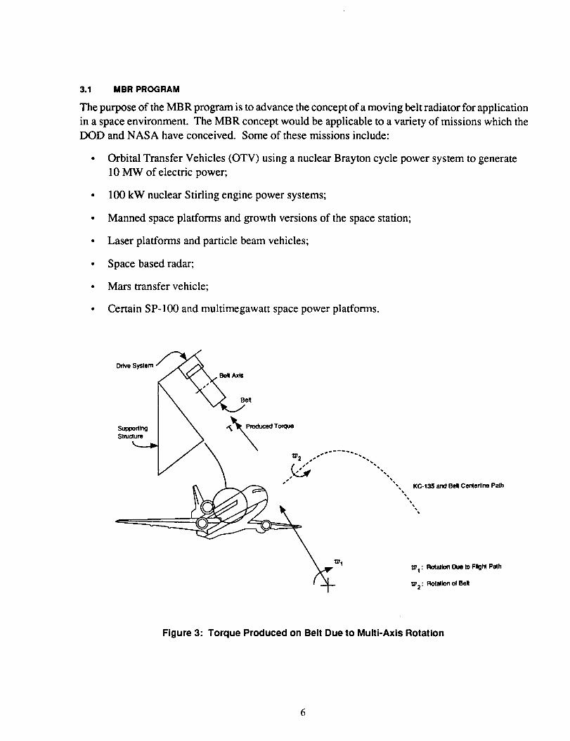
• Due to the size limitatic,ns of the KC-135, the belt was oriented with the axis of the belt
parallel to the axis of the aircraft; this orientation allowed for the positioning of cameras
without using wide angle lenses which would distort the image. From this orientation a
gyroscopic torque is produced due to the rotation of the belt and the rotation of aircraft
transverse to its flight path, as shown in Figure 3. This torque produces second or third
order effects (twisting of the belt about its local vertical axis) which may combine with the
other low level forces to produce sufficient noise to prevent the accurate demonstration of
a MBR in zero gravity.
3.0 OBJECTIVES AND SCOPE
This document will describe ;t shuttle experiment which will demonstrate the dynamic, thermal,
and IHX characteristics/performance of a scaled down MBR system.
3.1 MBR PROGRAM
The purpose of the MBR program is to advance the concept of a moving belt radiator for application
in a space environment. The MBR concept would be applicable to a variety of missions which the
DOD and NASA have conceived. Some of these missions include:
• Orbital Transfer Vehicles (OTV) using a nuclear Brayton cycle power system to generate
10 MW of electric power;
• 100 kW nuclear Stifling engine power systems;
• Manned space platforms and growth versions of the space station;
• Laser platforms and particle beam vehicles;
• Space based radar;
• Mars transfer vehicle;
• Certain SP-100 and multimegawatt space power platforms.
Stmport_gStmclure
Belt
_ztIZ_ 1 : Rc4atlon Due Io FIIgM Path
._ : Rolallon of Bell_2
Figure 3: Torque Produced on Belt Due to Multi-Axis Rotation
6
The development of this type of radiator still requires considerable work in order to fully understand
the capabilities and the characteristics of a moving belt. The thermal characteristics are relatively
well understood, although some additional testing is required in order to verify the predicted energy
transfer to space. The dynamic characteristics are much more complex and require additional testing
and refinement of analysis. The evaluation of the dynamic characteristics are made more difficult
by utilizing a self-deployed belt with no support structure, which allows the belt to deviate from
the desired circular shape when accelerations are imposed.
Other aspects also must be cor sidered when looking at the feasibility of building MBRs which can
dissipate up to 200 MW, such as:
• The issues involved with the manufacture of the various components such as large belts
over 300 cm (120 in) width with the accompanying rollers and seals.
• Extensive testing of belt materials and working fluids is required. This testing should
include the determination of belt mechanical properties (modulus of elasticity, density,
bending stiffness, damping, outgassing, etc.) and fluid properties (wettability, surface
tension, density, thermai conductivity, vapor pressure, etc.). The compatibility of various
belt materials, working fluids, and structural materials should also be examined. Initial
belt and fluid property measurements have been completed at ADL (Reference 3) for a
select group of candidat,_ materials.
• Improved configuration,', of the belts may be possible, and alternatives should be evaluated.
Configurations such as modular units, using inflatable belts to produce stiffer systems, and
using phase change materials within the belts both to improve the thermal characteristics
and to stiffen the system are options.
• The best approach to defending against natural or hostile attacks are key issues especially
for DOD applications. Should a belt be retracted if an attack is detected or is it best to use
evasive maneuvers? How much damage will occur in the event of a hit by micrometeorites
or meteoroids? It is exp,_cted that, although the belt may be punctured, the system should
still continue to operate with a slight reduction in capacity. But testing and the impact on
the tracking and drive system are open issues.
• During maneuvers the available options are retraction of the belt or allowing the belt to
deform and then return to its original shape. If the belt is retracted then the spacecraft must
be able to store or reduce the generation of waste energy during the maneuver. By leaving
the belt deployed durini_, a maneuver the acceleration will be limited by the allowable
deformation of the belt or the strength of the belt.
3.2 SHUTTLE EXPERIMENT
The shuttle experiment is a continuation of the work which has been completed by ADL. The
primary purpose of this experiment will be to demonstrate the dynamic characteristics of a MBR
system, with secondary goals of demonstrating the thermal behavior and the sealing of an IHX
containingfluid. Theverificationof thedynamiccharacteristicswill alsoallow for refinementsinthe Belt RadiationSimulation (BERS)computercodeso that thebehaviorof larger beltscanbepredictedmoreaccuratelywith lessexperimentation.
Noneof the work which hasbeencompletedindicatesthat thereareanymajor technicalbarriersin thedevelopmentof a full scaleMBR system. Theexperimentson the KC-135 indicate thatastablebelt shapeis possibleif thedynamicnoiseproducedby theKC-135 environmentis reduced.The problemsassociatedwith testingin the KC-135 which werelisted in Section2.2 would, in aspaceshuttle,bereducedto secondor thirdordereffects. Also, theaerodynamiceffectswouldbereducedsignificantly in a shuttle flight. Therefore,a shuttle experiment would endeavortodemonstratethedynamicandthermalcharacteristicsin anenvironmentwhich is morerealisticofthe true operating environmentof a fully operationalMBR system. The featuresof a shuttleexperimentwould include:
• No influencefrom air currents;
• KC-135 variablegravity levelsreducedsignificantly;
• Belt diametersbetween120and300cm (48 to 120in) possible;
• A very flexible belt which requiresmore than20 secondsto dampout perturbationscanbeexamined;
• A completeworking modelof a MBR canbedemonstrated.
4.0 ANALYSIS
4.1 DYNAMIC ANALYSIS
The dynamics of the MBR are complex, particularly during deployment and when perturbed by
short or long term acceleration fields. In recognition of this, ADL has developed a unique computer
modeling program which allows for the dynamic analyses of rotating belts as a function of their
physical characteristics and imposed acceleration fields along several selected axes. The BERS
program simulates the dynamics of a ribbon rotating in a given acceleration field while being
constrained over a prescribed arc length (the drive system). This model uses a lumped-parameter
representation of the MBR structure. A discussion on the development of the equations is presented
in References 3 and 4. The results of this model indicate that:
• The equilibrium shape of the MBR structure is a hoop with the stiffness determined by belt
materials, physical dimensions, and angular velocity.
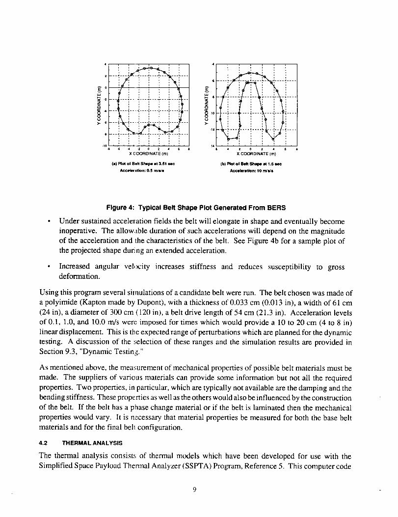
A short term physical disturbance, such as that resulting from a docking maneuver, should
damp out after a few belt revolutions. See Figure 4a for a sample plot of the predicted
shape during the short term acceleration.
4
2
A 0
-6
-t0-8
- ! i ' i !
i i _ i i i i
• i _ i * i
i , t _ J i
L ....
p i , t i i i, i , t i i i
• ! . ! . ! . ! . ! . ! , ! .
_6 4 -2 0 2 4 6
X (;OORDINATE (m)
(a) I=1ol of Bt4t Shape at 3.51 sec
Accelerltk)n: 0,5 m/s/s
-4 _ n i
_ -10 .............
-12 .... • .... L
* i
141L- 4 0 4
X COORDINATE (m)
ii
i
ii!!i iiiiii ....
i
(b) Plot ol Belt Shape at 1.5 sec
Acceleration: 10 nVs/s
Figure 4: Typical Belt Shape Plot Generated From BERS
Under sustained acceleration fields the belt will elongate in shape and eventually become
inoperative. The allowable duration of such accelerations will depend on the magnitude
of the acceleration and the characteristics of the belt. See Figure 4b for a sample plot of
the projected shape du_ ng an extended acceleration.
• Increased angular velocity increases stiffness and reduces susceptibility to gross
deformation.
Using this program several simulations of a candidate belt were run. The belt chosen was made of
a polyimide (Kapton made by Dupont), with a thickness of 0.033 cm (0.013 in), a width of 61 cm
(24 in), a diameter of 300 cm (120 in), a belt drive length of 54 cm (21.3 in). Acceleration levels
of 0.1, 1.0, and 10.0 rn/s were imposed for times which would provide a 10 to 20 cm (4 to 8 in)
linear displacement. This is tl_e expected range of perturbations which are planned for the dynamic
testing. A discussion of the .';election of these ranges and the simulation results are provided in
Section 9.3, "Dynamic Testing."
As mentioned above, the measurement of mechanical properties of possible belt materials must be
made. The suppliers of varieus materials can provide some information but not all the required
properties. Two properties, in particular, which are typically not available are the damping and the
bending stiffness. These prope rties as well as the others would also be influenced by the construction
of the belt. If the belt has a phase change material or if the belt is laminated then the mechanical
properties would vary. It is necessary that material properties be measured for both the base belt
materials and for the final bell configuration.
4.2 THERMAL ANALYSIS
The thermal analysis consist.,; of thermal models which have been developed for use with the
Simplified Space Payload Thermal Analyzer (SSPTA) Program, Reference 5. This computer code
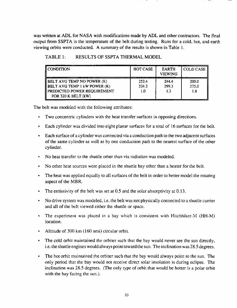
waswritten atADL for NASA with modificationsmadeby ADL andothercontractors.Thefinaloutput from SSPTA is thetemperatureof the belt during testing. Runsfor a cold,hot, andearthviewing orbits wereconducted. A summaryof theresultsis shownin Table 1.
TABLE 1: RESULTSOF SSPTATHERMAL MODEL
CONDITION
BELT AVG TEMP NO POWER (K)
BELT AVG TEMP 1 kW POWER (K)
PREDICTED POWER REQUIREMENT
FOR 320 K BELT [kW]
HOT CASE
252.4
324.3
1.0
EARTH
VIEWING
244.4
299.3
1.3
COLD CASE
200.0
275.0
1.8
The belt was modeled with the following attributes:
• Two concentric cylinders with the heat transfer surfaces in opposing directions.
• Each cylinder was divided into eight planar surfaces for a total of 16 surfaces for the belt.
Each surface of a cylinder was connected via a conduction path to the two adjacent surfaces
of the same cylinder as well as by one conduction path to the nearest surface of the other
cylinder.
• No heat transfer to the shuttle other than via radiation was modeled.
• No other heat sources were placed in the shuttle bay other than a heater for the belt.
• The heat was applied equally to all surfaces of the belt in order to better model the rotating
aspect of the MBR.
• The emissivity of the belt was set at 0.5 and the solar absorptivity at 0.13.
• No drive system was modeled, i.e. the belt was not physically connected to a shuttle carrier
and all of the belt viewed either the shuttle or space.
• The experiment was placed in a bay which is consistent with Hitchhiker-M (HH-M)
location.
• Altitude of 300 km (160 nmi) circular orbit.
• The cold orbit maintained the orbiter such that the bay would never see the sun directly,
i.e. the shuttle engines would always point toward the sun. The inclination was 28.5 degrees.
The hot orbit maintained the orbiter such that the bay would always point to the sun. The
only period that the bay would not receive direct solar insolation is during eclipse. The
inclination was 28.5 degrees. (The only type of orbit that would be hotter is a polar orbit
with the bay facing the sun.).
10
The earth viewing (ba_, facing earth) orbit which is one of the most common shuttle
orientations provides a less hostile temperature environment. The inclination was 28.5
degrees.
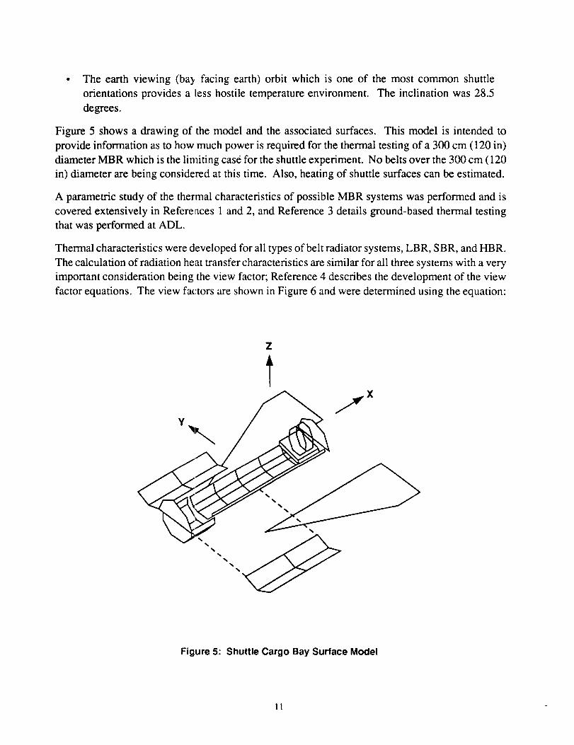
Figure 5 shows a drawing of the model and the associated surfaces. This model is intended to
provide information as to how much power is required for the thermal testing of a 300 cm (120 in)
diameter MBR which is the limiting case for the shuttle experiment. No belts over the 300 cm (120
in) diameter are being considered at this time. Also, heating of shuttle surfaces can be estimated.
A parametric study of the thermal characteristics of possible MBR systems was performed and is
covered extensively in References 1 and 2, and Reference 3 details ground-based thermal testing
that was performed at ADL.
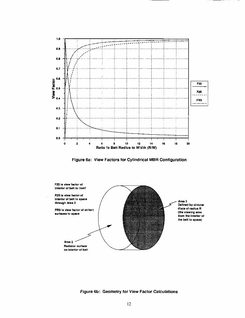
Thermal characteristics were developed for all types of belt radiator systems, LBR, SBR, and HBR.
The calculation of radiation heat transfer characteristics are similar for all three systems with a very
important consideration being the view factor; Reference 4 describes the development of the view
factor equations. The view factors are shown in Figure 6 and were determined using the equation:
Y
J
%
%%
Figure 5: Shuttle Cargo Bay Surface Model
11
1.0
O.9
0.8
0.7
_. 0.6
14. 0.5
!:) 0.4
0.3
0.2
0.1
0.0
: : : _"_ __ __..___ __..._;.-------_ _
. ..-f'T.'" ..:. ..... T--- !--;';,.': ........ ": " ! ! i/i .-" i i i
"'"/..... i;.......... _............ "........... i........... _........... _............t,
J lI ;
II :
i I
I
...... 1 ................................................ _"........... t ............ ',
2 4 6 8 10 12 14 16 18
Ratio fo Belt Radius to Width (R/W)
F22
F2S
FRS
2O
Figure 6a: View Factors for Cylindrical MBR Configuration
F22 is view factor o!
Interior of belt to itself
F2S is view factor of
interior of belt to space
through Area 3
FRS Is view factor of all belt
surfaces to space
Area 3
Defined by circulardiscs of radius R
(the viewing area
from the interior of
the belt to space)
Area 2
Radiator surface
on interior of belt
Figure 6b: Geometry for View Factor Calculations
12
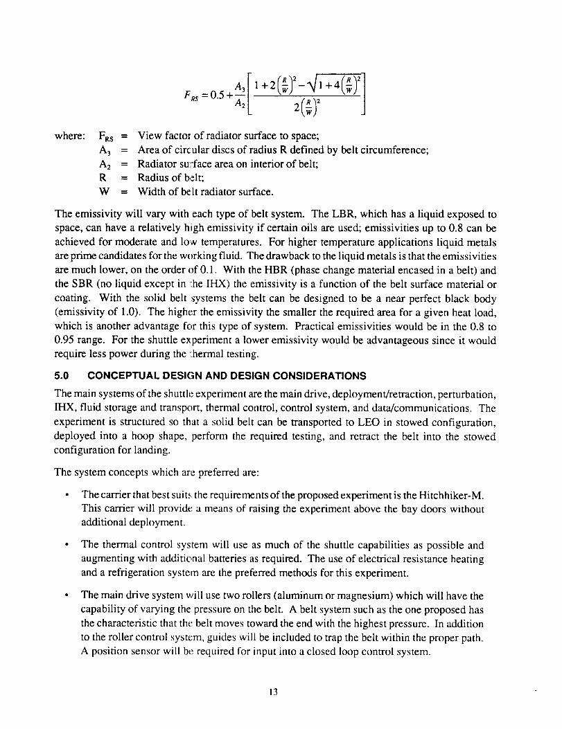
[ 2]+,43 1+2 _ - +4
FRs =0.5 A2 2(_)
where: FRS =
A3 =
A 2 =
R =
W =
View factor of radiator surface to space;
Area of circular discs of radius R defined by belt circumference;
Radiator su:,-face area on interior of belt;
Radius of belt;
Width of be It radiator surface.
The emissivity will vary with each type of belt system. The LBR, which has a liquid exposed to
space, can have a relatively high emissivity if certain oils are used; emissivities up to 0.8 can be
achieved for moderate and low temperatures. For higher temperature applications liquid metals
are prime candidates for the working fluid. The drawback to the liquid metals is that the emissivities
are much lower, on the order of 0.1. With the HBR (phase change material encased in a belt) and
the SBR (no liquid except in _:he IHX) the emissivity is a function of the belt surface material or
coating. With the solid belt systems the belt can be designed to be a near perfect black body
(emissivity of 1.0). The higher the emissivity the smaller the required area for a given heat load,
which is another advantage for this type of system. Practical emissivities would be in the 0.8 to
0.95 range. For the shuttle experiment a lower emissivity would be advantageous since it would
require less power during the ,:hermal testing.
5.0 CONCEPTUAL DESIGN AND DESIGN CONSIDERATIONS
The main systems of the shuttle experiment are the main drive, deployment/retraction, perturbation,
IHX, fluid storage and transport, thermal control, control system, and data/communications. The
experiment is structured so that a solid belt can be transported to LEO in stowed configuration,
deployed into a hoop shape, perform the required testing, and retract the belt into the stowed
configuration for landing.
The system concepts which are preferred are:
The carrier that best suit_,, the requirements of the proposed experiment is the Hitchhiker-M.
This carrier will provide" a means of raising the experiment above the bay doors without
additional deployment.
The thermal control system will use as much of the shuttle capabilities as possible and
augmenting with additic,nal batteries as required. The use of electrical resistance heating
and a refrigeration system are the preferred methods for this experiment.
The main drive system will use two rollers (aluminum or magnesium) which will have the
capability of varying the pressure on the belt. A belt system such as the one proposed has
the characteristic that the belt moves toward the end with the highest pressure. In addition
to the roller control system, guides will be included to trap the belt within the proper path.
A position sensor will bc required for input into a closed loop control system.
13
The deployment/retraction(D/R) systemwill consistof two rollers (identical to the main
drive rollers), a storage box, and a drive motor. During the deployment and operation of
the experiment the D/R system will not have any function except for providing idler rollers.
During the retraction of the belt the D/R motor and rollers will act as the drive system
which will stuff the belt into the storage box.
The belt material will be either Kapton or Teflon. Kapton and Teflon are relatively isotropic
which is an advantage for these materials. Kapton can be made in a maximum thickness
of 5 mils and any thicker sections would be laminates of 5 mil strips which could pose
problems of delamination. Further examination of Kapton and Teflon will have to be
completed, such as testing of mechanical properties, compatibility to possible working
fluids, resistance to permanent folds, and effects of a laminate structure on the mechanical
properties.
• The belt diameter should be in the 120 to 185 cm (48 to 72 in) range. This would allow
the belt to be contained within the shuttle bay.
Gallium is the prime candidate for the IHX fluid but other liquids should be examined for
applicability to this experiment. This type of research would be completed in Phase B of
the proposed experiment.
The conceptual design of the MBR experiment is shown in Figure 7. This design is still relatively
generic in that it will accommodate a variety of belt sizes and materials, a variety of working fluids,
and a variety of operating conditions.
The primary features that are desired in this experiment are the capability for dynamic testing with
minimal risks for the shuttle and crew. The addition of thermal testing would allow for the
demonstration of an operating MBR. The criteria for selecting components and materials are:
• Compatibility with low earth orbit environment (atomic oxygen, high ultraviolet radiation,
other cosmic radiation, vacuum, etc.);
• Meets the shuttle safety requirements (approved materials, operation within shuttle
capabilities, etc.)
• Meets all shuttle vibration and stress conditions (during lift-off, orbit, and re-entry);
• Redundancy in mechanical systems when feasible;
• Redundancy in data collection systems when feasible;
• Ability to operate within the thermal limits of the specific shuttle mission;
• Power, cooling, mass, and size limitations of an experiment using the specified carrier.
14
Belt StorageContainer
Drive Motors
Electronic
Working FluidStorage Tank
Belt Travel
Belt
- Primary Drive Rollers
Heal Exchanger
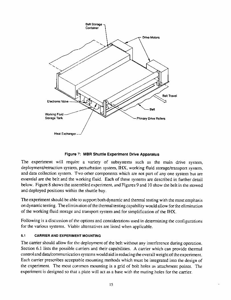
Figure _': MBR Shuttle Experiment Drive Apparatus
The experiment will require a variety of subsystems such as the main drive system,
deployment/retraction system, perturbation system, IHX, working fluid storage/transport system,
and data collection system. Two other components which are not part of any one system but are
essential are the belt and the working fluid. Each of these systems are described in further detail
below. Figure 8 shows the assembled experiment, and Figures 9 and 10 show the belt in the stowed
and deployed positions within the shuttle bay.
The experiment should be able to support both dynamic and thermal testing with the most emphasis
on dynamic testing. The elimination of the thermal testing capability would allow for the elimination
of the working fluid storage and transport system and for simplification of the IHX.
Following is a discussion of the options and considerations used in determining the configurations
for the various systems. Viable alternatives are listed when applicable.
5.1 CARRIER AND EXPERIMEHT MOUNTING
The carrier should allow for the deployment of the belt without any interference during operation.
Section 6.1 lists the possible c;trriers and their capabilities. A carrier which can provide thermal
control and data/communicatio_a systems would aid in reducing the overall weight of the experiment.
Each carrier prescribes acceptable mounting methods which must be integrated into the design of
the experiment. The most common mounting is a grid of bolt holes as attachment points. The
experiment is designed so that a plate will act as a base with the mating holes for the carrier.
15
ar IliI
"'--I
IilI:I
U L_J
_(I!
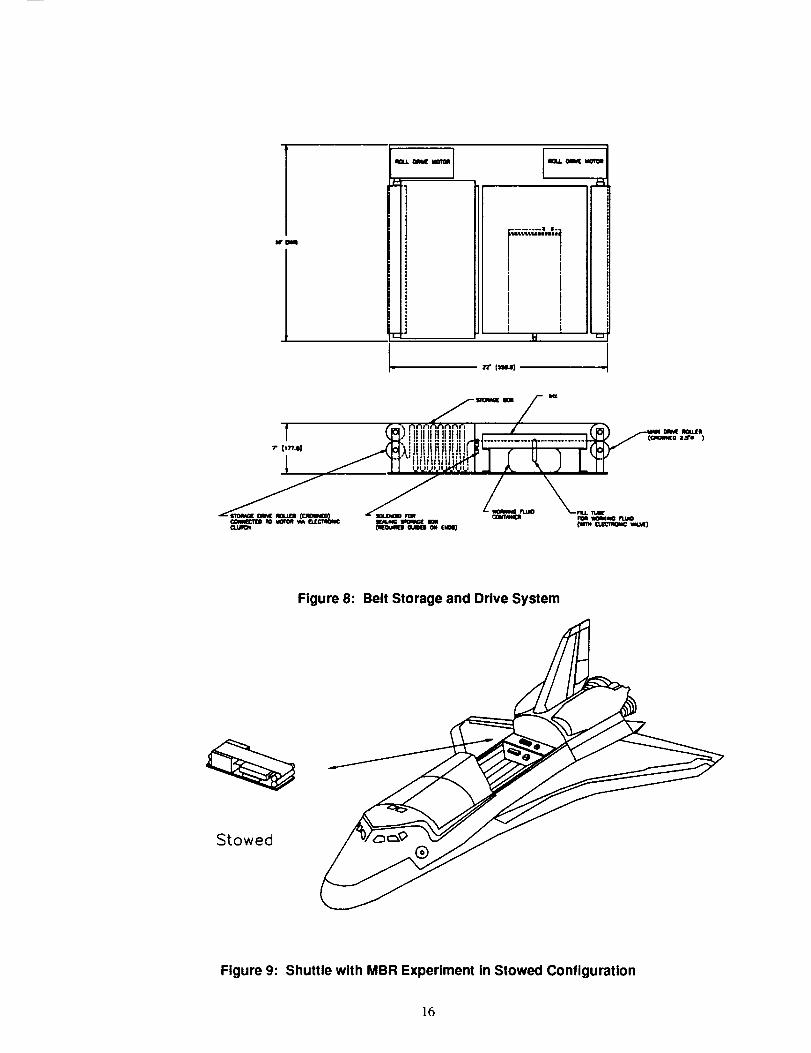
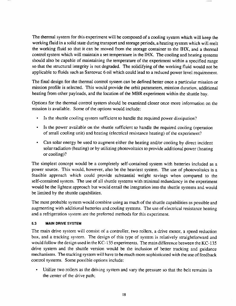
Figure 8: Belt Storage and Drive System
Stowed
Figure 9: Shuttle with MBR Experiment in Stowed Configuration
[6
Deployed
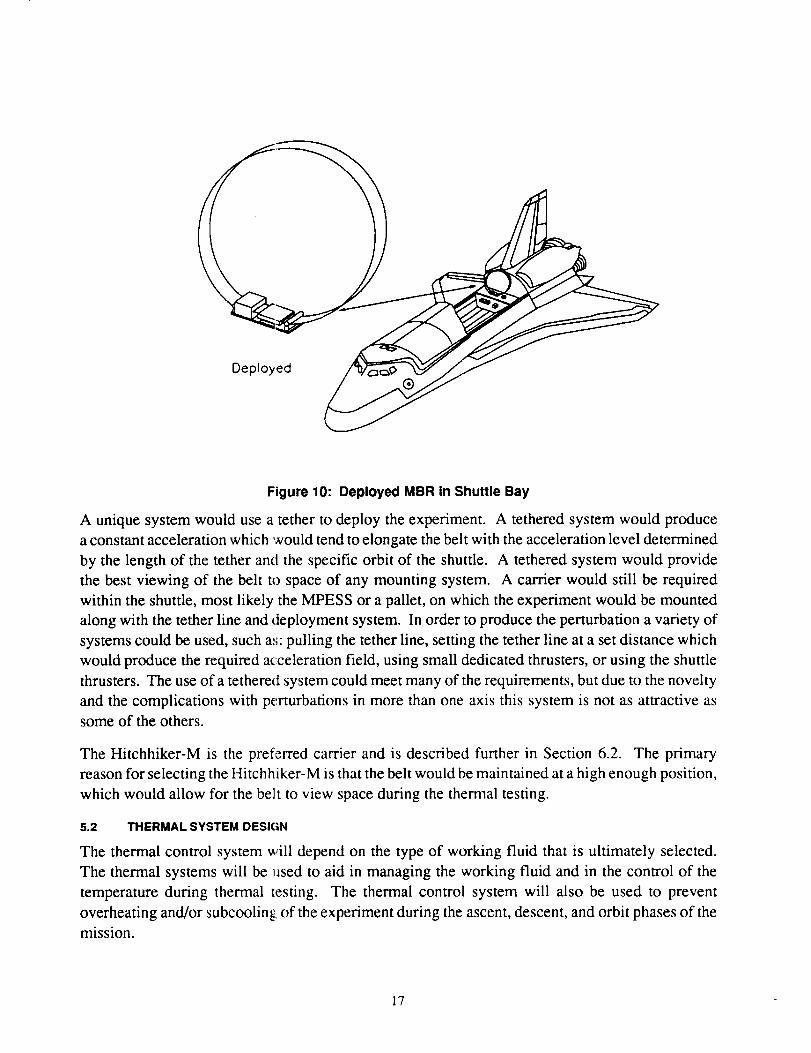
Figure 10: Deployed MBR in Shuttle Bay
A unique system would use a tether to deploy the experiment. A tethered system would produce
a constant acceleration which would tend to elongate the belt with the acceleration level determined
by the length of the tether and the specific orbit of the shuttle. A tethered system would provide
the best viewing of the belt to space of any mounting system. A carrier would still be required
within the shuttle, most likely the MPESS or a pallet, on which the experiment would be mounted
along with the tether line and deployment system. In order to produce the perturbation a variety of
systems could be used, such as: pulling the tether line, setting the tether line at a set distance which
would produce the required acceleration field, using small dedicated thrusters, or using the shuttle
thrusters. The use of a tethered system could meet many of the requirements, but due to the novelty
and the complications with perturbations in more than one axis this system is not as attractive as
some of the others.
The Hitchhiker-M is the preferred carrier and is described further in Section 6.2. The primary
reason for selecting the Hitchhiker-M is that the belt would be maintained at a high enough position,
which would allow for the belt to view space during the thermal testing.
5.2 THERMAL SYSTEM DESIGN
The thermal control system will depend on the type of working fluid that is ultimately selected.
The thermal systems will be used to aid in managing the working fluid and in the control of the
temperature during thermal testing. The thermal control system will also be used to prevent
overheating and/or subcoolingl of the experiment during the ascent, descent, and orbit phases of the
mission.
17
The thermal system for this experiment will be composed of a cooling system which will keep the
working fluid in a solid state during transport and storage periods, a heating system which will melt
the working fluid so that it can be moved from the storage container to the IHX, and a thermal
control system which will maintain a set temperature in the IHX. The cooling and heating systems
should also be capable of maintaining the temperature of the experiment within a specified range
so that the structural integrity is not degraded. The solidifying of the working fluid would not be
applicable to fluids such as Santovac 6 oil which could lead to a reduced power level requirement.
The final design for the thermal control system can be defined better once a particular mission or
mission profile is selected. This would provide the orbit parameters, mission duration, additional
heating from other payloads, and the location of the MBR experiment within the shuttle bay.
Options for the thermal control system should be examined closer once more information on the
mission is available. Some of the options would include:
• Is the shuttle cooling system sufficient to handle the required power dissipation?
• Is the power available on the shuttle sufficient to handle the required cooling (operation
of small cooling unit) and heating (electrical resistance heating) of the experiment?
Can solar energy be used to augment either the heating and/or cooling by direct incident
solar radiation (heating) or by utilizing photovoltaics to provide additional power (heating
or cooling)?
The simplest concept would be a completely self-contained system with batteries included as a
power source. This would, however, also be the heaviest system. The use of photovoltaics is a
feasible approach which could provide substantial weight savings when compared to the
self-contained system. The use of all shuttle systems with minimal redundancy in the experiment
would be the lightest approach but would entail the integration into the shuttle systems and would
be limited by the shuttle capabilities.
The most probable system would combine using as much of the shuttle capabilities as possible and
augmenting with additional batteries and cooling systems. The use of electrical resistance heating
and a refrigeration system are the preferred methods for this experiment.
5.3 MAIN DRIVE SYSTEM
The main drive system will consist of a controller, two rollers, a drive motor, a speed reduction
box, and a tracking system. The design of this type of system is relatively straightforward and
would follow the design used in the KC- 135 experiments. The main difference between the KC- 135
drive system and the shuttle version would be the inclusion of better tracking and guidance
mechanisms. The tracking system will have to be much more sophisticated with the use of feedback
control systems. Some possible options include:
• Utilize two rollers as the driving system and vary the pressure so that the belt remains in
the center of the drive path;
18
• Utilize two setsof drive rollerswhichcanrotateindependentlyof eachotherandvary thedriving speedsof eachc,f theroller sets,i.e. oneroller atv_andthe secondat v2;
• Useacrownedroller to reducethemisalignmentof thedriving roller set;
• Relyon the IHX, storage; box, and other guides to lock the belt in place; this would require
that the rollers be aligned very accurately.
The preferred system would be to use a crowned roller with a closed loop control system which
would adjust the pressure as needed to maintain the belt in the center of the drive path. The IHX,
storage box, and other guides will be included as the baseline tracking system with the closed loop
control system to improve the overall tracking.
All of the mechanical parts will have to meet stringent weight and low earth orbit compatibility
requirements. The ability to lock all rollers will be required in order to prevent the belt from
deploying prematurely or after storage.
5.4 DEPLOYMENT/RETRACTION SYSTEM
The deployment/retraction system will have a drive system separate from the main drive system,
this primarily for reduction of gearing and clutches. Figure 8 shows the deployment/retraction
system. This system consists of a storage box, a set of drive rollers, a motor, and a clamping system
for the exit of the storage box During ascent all the rollers would be locked and the storage box
would be closed off. The operation of the deployment/retraction system is described in Section
9.2. The clamping system is used to close off the exit of the storage box so that the belt will not be
pushed out during storage.
The rollers should be free to rotate with only the belt driving them. Minimal sliding should occur
between the rollers and belt sc that static electricity will not build up. A system for removing any
residual static electricity could be incorporated into the design. The static electricity could be
removed by a series of electrically conducting and grounded brushes or by relying on contact with
the metal components of the e_periment.
5.5 PERTURBATION SYSTEM
The perturbation system which will provide the required accelerations will be one of three types:
a mechanical system; the shuttle attitude thrusters; or small dedicated thrusters. The use of shuttle
thrusters must be discussed with NASA personnel and integrated into the specific mission. The
control of the thrusters should be fine enough so that very accurate pulses can be imposed (on the
order of 0.2 to 5 seconds with accelerations of 0.1 to 10.0 m/s2).
The mechanical system would,zonsist of some type of linear motion system, possibly an air cylinder
or electronic solenoid, which would connect the experiment platform to the carrier. This type of
system would be heavier but may impact less on a shuttle mission. A possibility might be to use a
combination of the shuttle thrusters and a mechanical system to provide the most efficient use of
power for the perturbations. The impact on the dynamics of the experiment must be analyzed for
resonant frequencies, etc.
19
If a tetheredsystemwere to beusedthensmall thrusters,possiblyusingnitrogen,argon,or someothergas,could be implemented. The accelerationswould be limited by theeffectsof the tetherradius. Additional accelerationscould beprovidedby varyingthetetherlength.
5.6 BELT SELECTION
The belt selection criteria will include:
Compatibility with low earth orbit environment, i.e. exposure to atomic oxygen, resistance
to ultraviolet energy, resistance to outgassing, and effects of temperature extremes;
Compatibility with working fluid;
• Mechanical properties, i.e. modulus of elasticity, density, strength, and maximum allowable
bending;
• An isotropic material would be preferred since this would eliminate the need for additional
parameters in the dynamic analysis of the belt;
• The thermal/optical properties, i.e. the emissivity, transmissivity, and reflectivity.
A desirable, but not necessary, criteria for belt material selection would be that the same type of
material is a candidate for use in actual MBR systems. This would allow not only for the testing
of the thermal and dynamic characteristics of a scaled down version of a MBR but also for a scaled
down version of the belt itself. Some materials such as polyimides would be best suited for non-LEO
missions due to the interaction with the earth's atmosphere. Other materials would be well suited
for both LEO and non-LEO missions. The basic list of potential belt materials includes: polyimides
(Kapton® made by Dupont and Alcar® made by Allied-Signal), Teflon®, Lexan®, nylon, Vespel®,
tantalum, aluminum, and titanium.
One of the most important criteria which will limit the materials that can be used for the belt will
be the compatibility with the low earth environment. This will be the first criteria that all candidates
must meet and from this a handful of possible materials should emerge. Some of the materials that
should meet this criteria are listed above. The most likely candidates would be the polymeric
materials since these would tend to be the lightest and pose the least danger. The polymers will,
however, be affected more by the ultraviolet radiation, molecular oxygen, and outgassing. The
allowable temperature of a polymer also tends to be more restrictive than that of a metal.
The compatibility of the belt with the working fluid will eliminate some combinations such as an
aluminum belt and gallium as the working fluid. Additional research and compatibility tests will
be required during the final design. The compatibility requirement need only be that the two
materials can coexist for approximately one hour with minimal degradation of the belt or
contamination of the working fluid. The belt cannot disassociate, tear, fracture, or otherwise become
separated or weakened after only one hour of use. If the working fluid does degrade the belt, then
its ends would be loose in the shuttle bay; they would, however, remain tethered to the experiment
and the retraction system would still be able to stow the belt and avoid the possibility of loose ends
in the shuttle bay during landing.
20
The properties which are preferred in the belt material are primarily limited by the dynamic response
that is desired for the experiment. Although similarity to a full scale system is desired, this could
be achieved by varying the belt speed. The belt material that is chosen for the experiment would
be the same that could potentially be chosen for a full scale system. In order to increase the response
time (natural frequency) of the belt to a perturbation, the modulus of elasticity should be decreased
and the density increased, with the reverse holding true for a decrease in time response.
The strength should be sufficient, at operating temperatures, to maintain the integrity of the belt
due to the tensile forces produced by the centrifugal loads. The optical/thermal properties are of
prime interest in determining the power requirement during thermal testing and would have no
primary influence in the dynamic testing. The lower the emissivity, the lower the power requirement
will be during thermal testing;. With an extremely low emissivity the temperature may be too low
during non-thermal testing periods. A careful analysis and optimization is required to specify the
acceptable range of emissivities.
In relation to the mechanical properties, an isotropic material would be desired since this would
eliminate the complications of having a material which is stiffer in one direction than the other.
The effects of an anisotropic material would further complicate any analysis if the primary axes of
the material were not perpendicular and parallel to the belt edges.
For the shuttle experiment the leading candidate for a belt material is a polyimide such as Kapton.
Kapton will not be a candidate for long term LEO missions but could be used for non-LEO missions.
Kapton is relatively isotropic, which is another advantage of this material. Some of the disadvantages
are that Kapton can only be made in a maximum thickness of 5 mils and any thicker sections would
be laminates of 5 mil strips. Further examination of Kapton® will have to be completed, such as
testing of mechanical properti,_s, compatibility with possible working fluids, resistance to permanent
folds, and effects of a lamina:e structure on the mechanical properties.
A second alternative would be Teflon. Teflon provides an isotropic material which may be better
suited for LEO mission and would be a candidate for non-LEO missions. However, Teflon is more
likely to permanently crease _,nd would retain the folds which are formed during transport to LEO.
5.7 WORKING FLUID SELEC'r'ION
The working fluid should hav,: low vapor pressure, be nonwetting, and have relatively high thermal
conductivity.
The two primary criteria to be: evaluated, wettability and surface tension, are aimed at defining the
required sealing system. A fluid with a high surface tension requires either a larger pressure
difference or a larger leak site in order for the fluid to flow out. The high surface tension maintains
a meniscus which traps the fluid within the IHX. The nonwetting and high surface tension attributes
provide some important features:
• If the fluid is nonwetting and has high surface tension, then the seal design is simplified.
21
• If the fluid is nonwetting, then the probability of having fluid flow out of the IHX on the
belt is virtually eliminated.
• The other mode of leakage would be through an opening, but if the surface tension is high
then the allowable openings could be larger.
Some tests of fluid properties were conducted with the results presented in Reference 3.
The evaporation of the working fluid in space must be considered. A fluid with a low vapor pressure
reduces the evaporation rate at the low operating pressures in a space environment. Therefore, with
the low vapor pressure the need of maintaining a significant pressure difference between the IHX
interior and the local space environment (a vacuum) is eliminated. The use of gallium would negate
any effects of evaporation, while the use of other fluids, such as Santovac 6 oil, would require that
a sufficient replacement fluid be available to keep the IHX full. The weight of the experiment
would be affected and a series of trade-offs would be required. The trade-offs would include overall
weight, complexity of the experiment, reliability, safety, contamination, and simulation of possible
final configuration.
Gallium and Santovac 6 meet many of the requirements and are, therefore, prime candidates. Other
liquids, such as mercury (an unlikely choice), should be examined for applicability to this
experiment. Santovac 6 does not have the required vapor pressure or nonwetting attribute and
would, therefore, require a resupply of fluid and a more complicated seal design. Gallium has a
safety issue which must be addressed. Gallium attacks aluminum and must be contained with
sufficient safeguards to prevent leakage. The amount of gallium is small and any leakage would
most likely not compromise the structural integrity of the shuttle. The use of gallium on the shuttle
will be a key issue and will have to be discussed with NASA personnel.
5.8 WORKING FLUID CONTAINMENT
The seals that will be used would be similar to those tested in a previous task, namely, scraper seals.
The scraper seals will float on springs which will continuously apply pressure between the seals
and the belt. This type of seal will provide the most positive sealing system. The seals should be
compatible with the space environment and the working fluid. Some possible seal materials include
Rulon, Teflon, or some other type of elastomeric material. The detailed design depends on the fluid
which is selected--if a nonwetting fluid with high surface tension is used, then a soft seal would be
sufficient, while if a wetting fluid with low surface tension is used, the sealing becomes much more
difficult.
If the life of the seals proves to be an issue then a labyrinth seal can be used. These seals would
tend to increase the life of the sealing system since no constant and direct force is applied between
the seals and the belt. The labyrinth seals are not preferred for the shuttle experiment since life is
not a limiting factor and scraper seals provide a seal and clean the belt. For a final and full scale
design labyrinth seals may be required. Figure 11 shows possible configurations of labyrinth and
scraper seals.
22
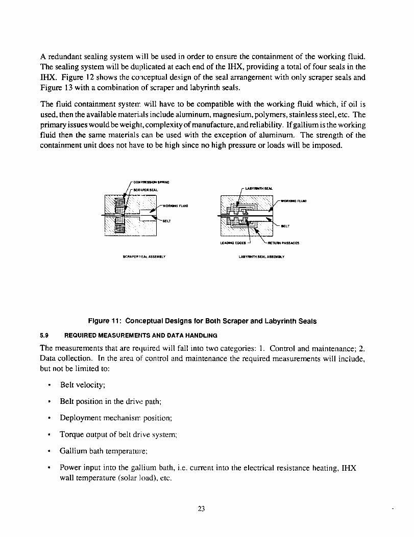
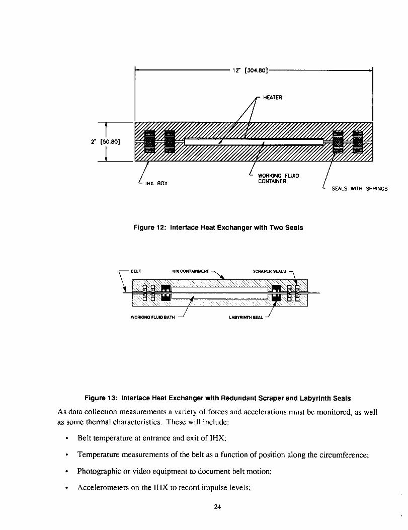
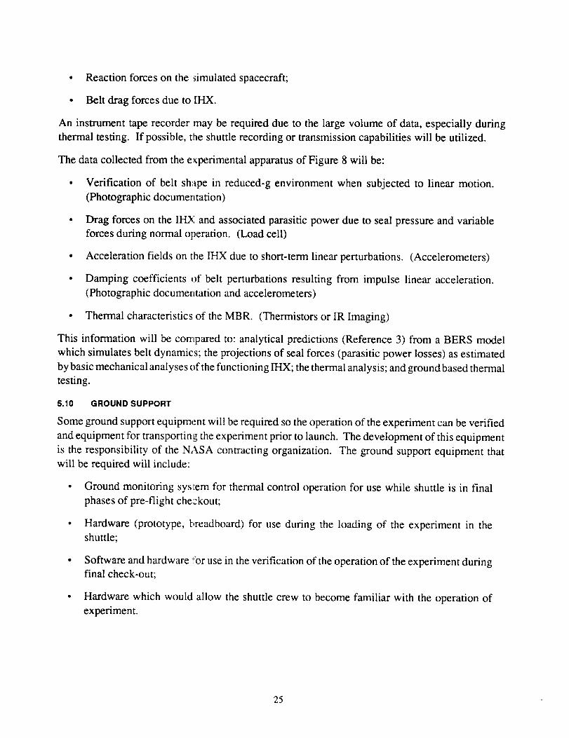
A redundant sealing system _ill be used in order to ensure the containment of the working fluid.
The sealing system will be duplicated at each end of the IHX, providing a total of four seals in the
IHX. Figure 12 shows the co aceptual design of the seal arrangement with only scraper seals and
Figure 13 with a combination of scraper and labyrinth seals.
The fluid containment systerr will have to be compatible with the working fluid which, if oil is
used, then the available materials include aluminum, magnesium, polymers, stainless steel, etc. The
primary issues would be weight, complexity of manufacture, and reliability. If gallium is the working
fluid then the same materials can be used with the exception of aluminum. The strength of the
containment unit does not have to be high since no high pressure or loads will be imposed.
s COU I_qESSION SPRINGSCR kPtER SEAL
_,_ i woRmoFLUm
...... BELT
SCRAPER_EALASSEMBLY
_ WORlaNG FLUIO
LABYRINTH SEAL ASS I[_1BLY
Figure 11 : Con(-eptual Designs for Both Scraper and Labyrinth Seals
5.9 REQUIRED MEASUREMEtiTS AND DATA HANDLING
The measurements that are required will fall into two categories: 1. Control and maintenance; 2.
Data collection. In the area of control and maintenance the required measurements will include,
but not be limited to:
• Belt velocity;
• Belt position in the drive path;
• Deployment mechanisrc position;
• Torque output of belt drive system;
• Gallium bath temperatu]e;
• Power input into the ga]lium bath, i.e. current into the electrical resistance heating, IHX
wall temperature (solar ]oad), etc.
23
- _2" [:3o4.8o] ,_
2"1
[50.80]
HEATER
NWORKING FLUID
HX BOX CONTAINER / SEALS WITH SPRINGS
Figure 12: Interface Heat Exchanger with Two Seals
-- BELT IHX CONTAINMENT SCRAPER SEALS
WORKING FLUID BATH LABYRINTH SEAL
Figure 13: Interface Heat Exchanger with Redundant Scraper and Labyrinth Seals
As data collection measurements a variety of forces and accelerations must be monitored, as well
as some thermal characteristics. These will include:
• Belt temperature at entrance and exit of IHX;
• Temperature measurements of the belt as a function of position along the circumference;
• Photographic or video equipment to document belt motion;
• Accelerometers on the IHX to record impulse levels;
24
• Reaction forces on the simulated spacecraft;
• Belt drag forces due to IHX.
An instrument tape recorder may be required due to the large volume of data, especially during
thermal testing. If possible, the shuttle recording or transmission capabilities will be utilized.
The data collected from the e_perimental apparatus of Figure 8 will be:
• Verification of belt shape in reduced-g environment when subjected to linear motion.
(Photographic documentation)
• Drag forces on the IHX and associated parasitic power due to seal pressure and variable
forces during normal operation. (Load cell)
• Acceleration fields on the IHX due to short-term linear perturbations. (Accelerometers)
• Damping coefficients of belt perturbations resulting from impulse linear acceleration.
(Photographic documerltation and accelerometers)
• Thermal characteristics of the MBR. (Thermistors or IR Imaging)
This information will be compared to: analytical predictions (Reference 3) from a BERS model
which simulates belt dynamics; the projections of seal forces (parasitic power losses) as estimated
by basic mechanical analyses of the functioning IHX; the thermal analysis; and ground based thermal
testing.
5.10 GROUND SUPPORT
Some ground support equipment will be required so the operation of the experiment can be verified
and equipment for transporting the experiment prior to launch. The development of this equipment
is the responsibility of the NASA contracting organization. The ground support equipment that
will be required will include:
• Ground monitoring system for thermal control operation for use while shuttle is in final
phases of pre-flight checkout;
• Hardware (prototype, breadboard) for use during the loading of the experiment in the
shuttle;
• Software and hardware for use in the verification of the operation of the experiment duringfinal check-out;
• Hardware which would allow the shuttle crew to become familiar with the operation of
experiment.
25
In addition to the hardware,manpowerat GoddardSpaceFlight Center(GSFC) and at JohnsonSpaceCenter(JSC)prior to launchandduringthemissionwill berequired.ThepersonnelatGSFCwill berequiredto aidin theproperinstallationof theexperimenton theshuttle/cartier,while thoseinvolved at JSCwill beusedeither to help in conductingtheexperimentor to provide technicalguidanceduring theexperimentoperation.
6.0 PAYLOAD CARRIERS
6.1 POSSIBLE CARRIERS
Due to the small mass (under 8000 Ibm) and the minimal number of requirements, this class of
payload is considered a secondary payload and should have minimal impact on a shuttle mission.
The amount of time, both for Mission Specialist and shuttle control, are limited to hours as opposed
to days, and the shuttle maneuvering must be limited such that other payloads are not affected.
The carriers which the shuttle typically accommodates are: the Hitchhiker-G (HH-G) and
Hitchhiker-M (HH-M) out of GSFC; Get Away Special (GAS) out of GSFC; Spartan Freeflyer out
of GSFC; pallets out ofJSC; Spacelab; and middeck experiments. Each of these carriers has unique
capabilities with some overlap in specific characteristics. The specific characteristics of each of
these carders are covered in References 4 and 5.
The two Hitchhiker carriers share similar constraints for the associated payloads. The mounting
surfaces are the differentiating factor; HH-M uses the Multi-Purpose Experiment Support Structure
(MPESS) while the HH-G uses an orbiter beam. The experiments can be mounted either by GAS
canisters, plate mounting, direct mounting, or combination mounting. Each of the different
mounting techniques allows for a maximum mass and mass distribution. The MPESS is a structure
which lies across the shuttle bay which can accommodate multiple payloads.
The GAS carrier system is self-contained and consists of an aluminum canister which completely
encapsulates the experiment. The integration of a GAS canister is one of the simplest, but is primarily
for experiments which are small and require no crew interaction.
The middeck experiments fit in lockers located in the crew compartments. The safety and size
constraints require that the experiment be small, provide no hazards for the crew, and only require
a reduced gravity environment. The experiment would not be exposed to a vacuum environment
since it would remain in the crew compartment.
The Spacelab provides a laboratory in space in which all of the shuttle services are available. The
Spacelab module is placed in the cargo bay and connected to the crew compartment via a tunnel.
Experiments can be deployed outside of the module or experiments can be conducted within. The
Mission Specialist is on hand to monitor these experiments.
The pallets are the general carders which provide a mounting surface which mates with the shuttle.
Pallets are typically used for primary cargos or for those which require full use of most of the shuttle
capabilities.
26
The Spartan Freeflyer is a system which is mounted on the MPESS during launch, but is deployed
using the RMS. The Spartan provides some limited attitude control and data recording capabilities.
6.2 SELECTED CARRIER
The carder that should provide the best compatibility with the objectives of this experiment while
minimizing the required space is the HH-M. This carrier uses the MPESS as a mounting structure
for multiple experiments. By using this carder, additional experiments could share the MPESS.
The HH-M uses the Small Payload of Opportunity Carrier (SPOC), originally developed for the
HH-G program. The HH-M ,,arrier can be considered either as a Small Payload Accommodation
(SPA) or as a Standard Mixed Cargo (SMC). In order for the MBR experiment to fly, as outlined
in this document, it will be required that the experiment fly as a SPA. This will allow the use of
more power, data communications, Mission Specialist time, and mission time. The disadvantages
would be less opportunity for manifesting and longer lead times (19 months) prior to launch. The
lead time is taken from the titre the Customer Payload Requirements (CPR) Document is filed until
the scheduled launch date. As a secondary payload, which all Hitchhiker systems are considered,
the operation of the experime_t must have limited impact on the overall mission. Requirements of
shuttle pointing and maneuw:ring must be limited to hours, not days, which is in line with the
proposed requirements of this experiment.
As a SMC the carrier would use the Standard Mixed Cargo Harness (SMCH). The HH-M can
provide the following support systems and capabilities:
• 12.5 kw-hr/day of energy;
• 1750 W of power at 28 VDC;
• 545 kg (1200 Ibm) ofrrLass:
• Cooling capability
• Data and communicaticn capability
6.3 OPTIONAL CARRIER
Spacelab would be the second choice for a carrier since the benefit of direct access by the Mission
Specialist exists. By providing for direct access any problems that may arise in the operation of
the system can be dealt with without any chance of EVA. The Mission Specialist would be trained
on the operation, assembly, and performance of the experiment which would allow for immediate
repair of any malfunctioning system. The redundancy in the operating systems could be eliminated
which would simplify the experiment design. The disadvantages are that the size would be limited
and no thermal testing could be accomplished within Spacelab. An option to deploy the experiment
from Spacelab may be viable and could be examined further.
27
7.0 REQUIREMENTS OF SHUTTLE
7.1 POWER
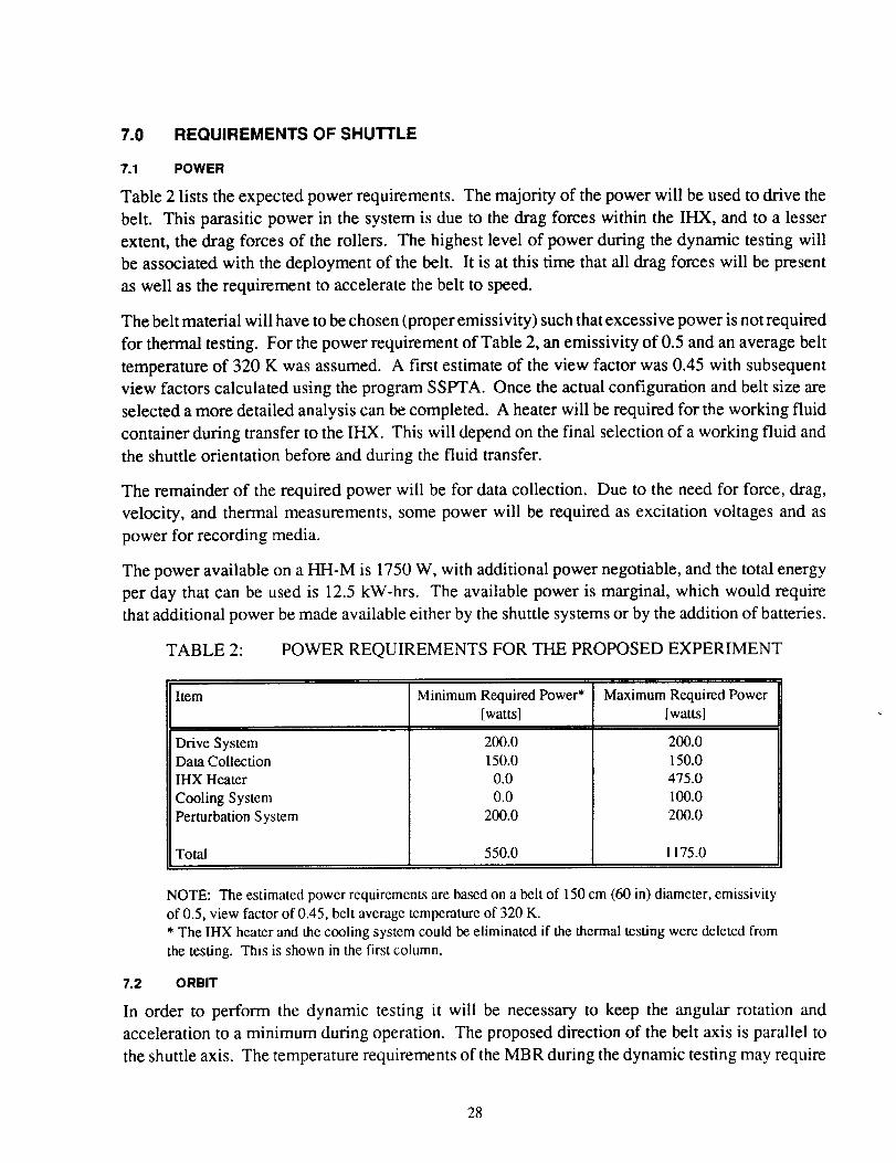
Table 2 lists the expected power requirements. The majority of the power will be used to drive the
belt. This parasitic power in the system is due to the drag forces within the IHX, and to a lesser
extent, the drag forces of the rollers. The highest level of power during the dynamic testing will
be associated with the deployment of the belt. It is at this time that all drag forces will be present
as well as the requirement to accelerate the belt to speed.
The belt material will have to be chosen (proper emissivity) such that excessive power is not required
for thermal testing. For the power requirement of Table 2, an emissivity of 0.5 and an average belt
temperature of 320 K was assumed. A first estimate of the view factor was 0.45 with subsequent
view factors calculated using the program SSPTA. Once the actual configuration and belt size are
selected a more detailed analysis can be completed. A heater will be required for the working fluid
container during transfer to the IHX. This will depend on the final selection of a working fluid and
the shuttle orientation before and during the fluid transfer.
The remainder of the required power will be for data collection. Due to the need for force, drag,
velocity, and thermal measurements, some power will be required as excitation voltages and as
power for recording media.
The power available on a HH-M is 1750 W, with additional power negotiable, and the total energy
per day that can be used is 12.5 kW-hrs. The available power is marginal, which would require
that additional power be made available either by the shuttle systems or by the addition of batteries.
TABLE 2: POWER REQUIREMENTS FOR THE PROPOSED EXPERIMENT
Item
Drive SystemData CollectionIHX Heater
Cooling System
Perturbation System
Total
Minimum Required Power*[watts]
200.0150.0
0.00.0
200.0
550.0
Maximum Required Power[watts]
200.0
150.0475.0
I00.0
200.0
1175.0
NOTE: The estimated power requirements are based on a belt of 150 cm (60 in) diameter, emissivityof 0.5, view factor of 0.45, belt average temperature of 320 K.
* The IHX heater and the cooling system could be eliminated if the thermal testing were deleted from
the testing. This is shown in the first column.
7.2 ORBIT
In order to perform the dynamic testing it will be necessary to keep the angular rotation and
acceleration to a minimum during operation. The proposed direction of the belt axis is parallel to
the shuttle axis. The temperature requirements of the MBR during the dynamic testing may require
28
that the shuttle rotate during its orbit or that a constant attitude be maintained (facing the earth) in
order to maintain a moderate temperature environment. The rotation rate must be kept low in order
to avoid unwanted accelerations on the belt.
During the thermal testing the radiator surface should have minimal incident or reflected solar
energy. This would require taat the shuttle bay be facing away from the earth and the sun.
7.3 TIME REQUIREMENTS
In order to conduct a comprehensive test at least two hours will be required. The test should include
as a minimum:
• Extended periods in steady state operation at various conditions (operating time of
approximately 30 minutes);
• Periods of perturbations and return to steady state (operating time of approximately one
hour);
• Thermal testing at various power levels (operating time of approximately one hour).
In addition to these phases of testing, a deployment and retraction sequence will have to be
performed. These two steps should not require more than ten minutes total. Finalization of the test
plan and required time must be negotiated with NASA personnel.
7.4 MASS ESTIMATE
The expected mass of the experiment is detailed in Table 3. Two estimates are listed in Table 3,
one for a system which will test a 150 cm (60 in) diameter belt and thermal testing with a second
estimate for a belt of the same size without thermal testing.
The mass estimates do not include the carrier and additional power supply (batteries). The listed
mass is only for the operating portion of the experiment. The additional power sources may not be
required, and if possible, will not be added to this experiment.
The mass estimates were calculated with the following assumptions:
• The belt is made of Ka?ton or a material of similar density with a thickness of 0.33 mm
(0.013 in);
• The drive system uses the lightest available motors and reduction boxes;
• All components are made of aluminum or a lighter material;
• The dimensions are tho_e shown in Figure 8.
The carrier mass of the MPESS is 815 kg (1800 Ibm) and that of the required attachment hardware
is approximately 180 kg (400 Ibm). The attachment hardware mass will vary depending on which
bay the carrier is mounted. The MPESS can carry up to 545 kg (1200 Ibm), which indicates that a
shared structure would be economically attractive.
29
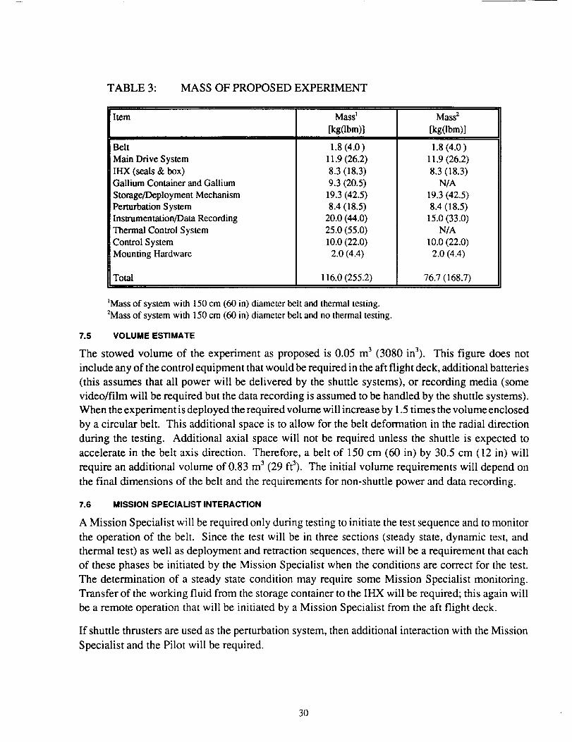
TABLE 3: MASS OF PROPOSED EXPERIMENT
Item
Belt
Main Drive SystemIHX (seals & box)Gallium Container and Gallium
Storage/Deployment MechanismPerturbation System
Instrumentation/Data RecordingThermal Control System
Control System
Mounting Hardware
Total
Mass 1
[kg(lbm)]
1.8 (4.0)
11.9 (26.2)8.3 (18.3)9.3 (20.5)
19.3 (42.5)8.4 (18.5)
20.0 (44.0)25.0 (55.0)
lO.O(22.0)2.0 (4.4)
116.0 (255.2)
Mass 2
[kg(lbm)l
1.8 (4.0)
11.9 (26.2)8.3 (18.3)
N/A19.3 (42.5)8.4 (18.5)
15.0 (33.0)N/A
lO.O(22.0)2.0 (4.4)
76.7 (168.7)
_Mass of system with 150 cm (60 in) diameter belt and thermal testing.2Mass of system with 150 cm (60 in) diameter belt and no thermal testing.
7.5 VOLUME ESTIMATE
The stowed volume of the experiment as proposed is 0.05 m 3 (3080 in3). This figure does not
include any of the control equipment that would be required in the aft flight deck, additional batteries
(this assumes that all power will be delivered by the shuttle systems), or recording media (some
video/film will be required but the data recording is assumed to be handled by the shuttle systems).
When the experiment is deployed the required volume will increase by 1.5 times the volume enclosed
by a circular belt. This additional space is to allow for the belt deformation in the radial direction
during the testing. Additional axial space will not be required unless the shuttle is expected to
accelerate in the belt axis direction. Therefore, a belt of 150 cm (60 in) by 30.5 cm (12 in) will
require an additional volume of 0.83 m 3 (29 ft3). The initial volume requirements will depend on
the final dimensions of the belt and the requirements for non-shuttle power and data recording.
7.6 MISSION SPECIALIST INTERACTION
A Mission Specialist will be required only during testing to initiate the test sequence and to monitor
the operation of the belt. Since the test will be in three sections (steady state, dynamic test, and
thermal test) as well as deployment and retraction sequences, there will be a requirement that each
of these phases be initiated by the Mission Specialist when the conditions are correct for the test.
The determination of a steady state condition may require some Mission Specialist monitoring.
Transfer of the working fluid from the storage container to the IHX will be required; this again will
be a remote operation that will be initiated by a Mission Specialist from the aft flight deck.
If shuttle thrusters are used as the perturbation system, then additional interaction with the Mission
Specialist and the Pilot will be required.
30
In the event of a system failure within the experiment, some Mission Specialist time will be required
to either correct the problem or to bypass the area of concern, thereby allowing for additional testing
and/or securing the experiment for the landing.
7.7 EVA AND RMS REQUIREMENTS
The use of the RMS and/or _ny EVA are not foreseen except in the event that the drive or belt
storage systems and all of the backups fail. Redundancy will be incorporated into every system to
minimize the chance that EVA will be required. The only system which, if failure occurred, would
require EVA is the belt storage system. The probability of the storage system not functioning
properly is unlikely since the _ystem will be tested extensively on the ground to prove the concept
and the operation/reliability.
In the event that the storage system and the backup does not function, then either the belt would
have to be left to float in the sauttle bay still tethered to the experiment or EVA would be required
to either stow the belt or to remove the belt. The tasks associated with any foreseen possible
malfunction will be outlined and discussed with the proper personnel, i.e. Mission Specialist in
charge of experiment operatic.n.
8.0 SAFETY ISSUES
8.1 WORKING FLUID CONTAINMENT
The working fluid containment will consist of a storage container for use during ascent and
pre-thermal testing, and a redundant sealing system in the IHX for use during thermal testing and
descent. The sealing system is shown in Figure 12 and the working fluid container in Figure 14.
The possibility of using three seals, one being a labyrinth seal, should be considered. Figure 13
shows this concept. This type of system would provide triple redundancy with the advantage of
having two different types of :;eals.
The working fluid could be a variety of substances, some of which are not compatible with direct
exposure to humans and others that would affect the shuttle construction materials, two examples
being mercury and gallium. Other substances would be more of a nuisance if any leakage occurred,
such as oil. Although the use of oil would not permanently damage most equipment, it could affect
the deployment or operation of some equipment.
The use of gallium as the working fluid reduces the opportunity of leakage due to the high surface
tension and the tendency to nonwetting. A fluid with a high surface tension would require a larger
opening (leak site) or a greater pressure difference to drive the fluid through a leak site. Also, by
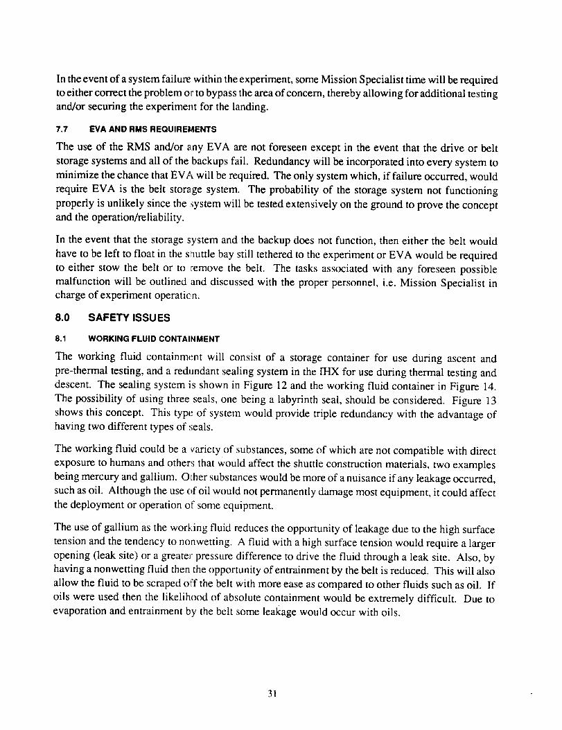
having a nonwetting fluid then the opportunity of entrainment by the belt is reduced. This will also
allow the fluid to be scraped off the belt with more ease as compared to other fluids such as oil. If
oils were used then the likelihood of absolute containment would be extremely difficult. Due to
evaporation and entrainment by the belt some leakage would occur with oils.
31
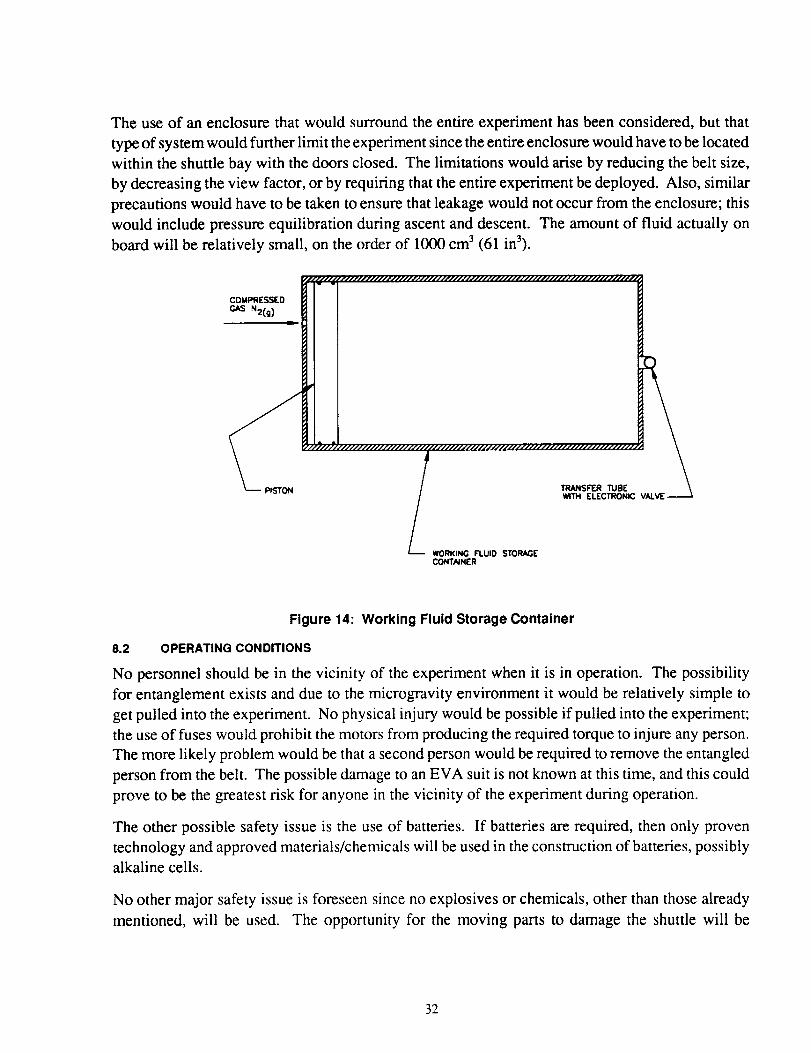
The use of an enclosure that would surround the entire experiment has been considered, but that
type of system would further limit the experiment since the entire enclosure would have to be located
within the shuttle bay with the doors closed. The limitations would arise by reducing the belt size,
by decreasing the view factor, or by requiring that the entire experiment be deployed. Also, similar
precautions would have to be taken to ensure that leakage would not occur from the enclosure; this
would include pressure equilibration during ascent and descent. The amount of fluid actually on
board will be relatively small, on the order of 1000 cm 3 (61 in3).
_llllllllllillllllll_ww
COMPRESSED
GAS N2(g )
¢
r/, _///////////////////#
TRANSFER TUnE
WITH ELECTRONIC
_-WORKING FLUID STORAGECONTAINER
Figure 14: Working Fluid Storage Container
8.2 OPERATING CONDITIONS
No personnel should be in the vicinity of the experiment when it is in operation. The possibility
for entanglement exists and due to the microgravity environment it would be relatively simple to
get pulled into the experiment. No physical injury would be possible if pulled into the experiment;
the use of fuses would prohibit the motors from producing the required torque to injure any person.
The more likely problem would be that a second person would be required to remove the entangled
person from the belt. The possible damage to an EVA suit is not known at this time, and this could
prove to be the greatest risk for anyone in the vicinity of the experiment during operation.
The other possible safety issue is the use of batteries. If batteries are required, then only proven
technology and approved materials/chemicals will be used in the construction of batteries, possibly
alkaline cells.
No other major safety issue is foreseen since no explosives or chemicals, other than those already
mentioned, will be used. The opportunity for the moving parts to damage the shuttle will be
32
minimized by encasing all drive system moving parts. The only moving part that will not be
completely encased will be the belt, however, since it will be rotating at a relatively low angular
velocity and will be made of a polymeric material, no serious damage to the shuttle is foreseen.
8.3 BACKUP SYSTEMS
The main safety issue is the presence of a fluid and the possibility of leakage. The backup seals
are incorporated into the design of the IHX and should provide adequate protection. With the
additional ground testing that would be conducted, a single sealing system could be proven to be
sufficient, but as is shown in Figure 12, a redundant sealing system is to be used. The potential for
a triple redundancy in the sealing system should be considered. If a triple redundancy is used then
at least one set of seals should be of a different type, such as a labyrinth seal. The likeliest leakage
points in the storage container would be the seams and connections between the various components.
These connection points would be welded or otherwise sealed to provide adequate containment.
No additional enclosures surrounding the entire experiment are incorporated into the design to catch
any fluid in the event of leakalge.
Unless a catastrophic failure occurs the leakage should be small, especially if a nonwetting fluid
such as gallium is used. The leak site would have to be substantial to allow the passage of gallium
out. The enclosure thickness would be selected to protect the system from micrometeroid damage.
Additional precautions are taken by maintaining the fluid in a solid state, if gallium is used, when
not in use so that leakage is not possible, although solid sublimation would still be possible. If an
oil is used then freezing the fluid would not be possible and the opportunity for leakage would be
present during non-use period:_.
8.4 POSSIBLE MALFUNCTIONSAND RESULTS
The possible malfunctions thai are envisioned at this time are as listed in Table 4; also included are
the possible results and corrections. Some of the malfunctions would not impair the operation of
the experiment or provide any dangerous situations, while others may force the shut down of the
experiment. One scenario which could require EVA is if both the main retraction system and its
backup were to fail. Additionzl safeguards could be incorporated into the experiment to reduce the
chance of EVA or RMS requirements.
9.0 TEST PLAN
9.1 REQUIRED GROUND TESTING
The testing that will be required prior to launch should include extensive testing of the IHX seals,
deployment and retraction sequences, and thermal testing of the system.
The seals should be tested in _t vacuum chamber using a vibration system, thermal extremes, and
thermal shock. The seals sho,ld be tested as a single set (two seals total, no redundancy) and in
the final configuration (four seals, redundancy)
33
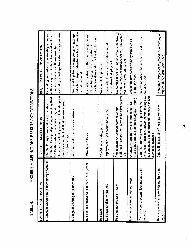
Z0
0
Z<
Z0
Z
IT.,
<
©
,<
I_ o
__
_!'_•- _
_ _r_
._
oe_
Z E
0 o
".._ 0
_o__
° " N-._
._., ,_
_.'_ _.
._ _ .- • _
_'___ _°= -'' _:_ _ _i
.=.
o
--' o_1 ,.lz
._--Z °
•.'.'_ ¢)
•._ ,: _._ _ "_ _•= . _ ._ =2 a
'-- ,,_
_-_ ,. ,,o -,:__ ._
_ _ Z • _ "__ _ _-_ _ o _. " ._ ._ .8 I•.- .,-:2 _ ,_
E
._ f_
._ _ _ o o
-g -g -g -g =
-ao
o
o
E
-i
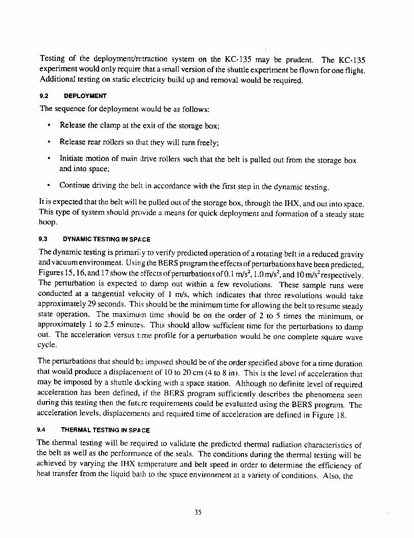
Testing of the deployment/retraction system on the KC-135 may be prudent. The KC-135
experiment would only require that a small version of the shuttle experiment be flown for one flight.
Additional testing on static electricity build up and removal would be required.
9.2 DEPLOYMENT
The sequence for deployment would be as follows:
• Release the clamp at the exit of the storage box;
• Release rear rollers so that they will turn freely;
• Initiate motion of main drive rollers such that the belt is pulled out from the storage box
and into space;
• Continue driving the belt in accordance with the first step in the dynamic testing.
It is expected that the belt will be pulled out of the storage box, through the IHX, and out into space.
This type of system should provide a means for quick deployment and formation of a steady statehoop.
9.3 DYNAMIC TESTING IN SP,_,CE
The dynamic testing is primaril y to verify predicted operation of a rotating belt in a reduced gravity
and vacuum environment. Usi_ g the BERS program the effects of perturbations have been predicted,
Figures 15, 16, and 17 show the effects of perturbations of 0.1 m/s 2, 1.0 m/s 2, and 10 m/s 2respectively.
The perturbation is expected to damp out within a few revolutions. These sample runs were
conducted at a tangential velocity of 1 m/s, which indicates that three revolutions would take
approximately 29 seconds. This should be the minimum time for allowing the belt to resume steady
state operation. The maximum time should be on the order of 2 to 5 times the minimum, or
approximately 1 to 2.5 minutes. This should allow sufficient time for the perturbations to damp
out. The acceleration versus t:me profile for a perturbation would be one complete square wavecycle.
The perturbations that should b_ imposed should be of the order specified above for a time duration
that would produce a displacement of 10 to 20 cm (4 to 8 in). This is the level of acceleration that
may be imposed by a shuttle docking with a space station. Although no definite level of required
acceleration has been defined, if the BERS program sufficiently describes the phenomena seen
during this testing then the futere requirements could be evaluated using the BERS program. The
acceleration levels, displacements and required time of acceleration are defined in Figure 18.
9.4 THERMAL TESTING IN SPACE
The thermal testing will be required to validate the predicted thermal radiation characteristics of
the belt as well as the performance of the seals. The conditions during the thermal testing will be
achieved by varying the IHX temperature and belt speed in order to determine the efficiency of
heat transfer from the liquid bath to the space environment at a variety of conditions. Also, the
35
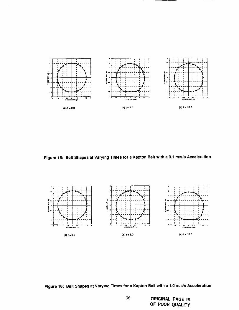
11
_- ns
I i I I I t
o o I I o o
+iii7
I I I I I I
_J
!°.
I I I I ! I
I I I I I I
•.__LI
• I
I I I I
:-r-q .... T--I ....
• I hi l I I I I
• I I I
I I I I
I I I I I I• + . : . A . , - , - , •
I C_ORDtNA_ lml
Z
_S
Kos
_°
.1
I I * I I I
I i I t I I
I I I I ,I
'--I -r-'l .... T--I .....
i i i i i
.-_- _-_ ........., , ,
I I t I I I
.is .i 4)i =s i 11
x clX_O+_wl_ (m)
(a)t =o.o (b) I : S.O (c)t =10.0
Figure 15: Belt Shapes at Varying Times for a Kapton Belt with a 0.1 m/s/s Acceleration
11
EOS
_s
I i I I I I
* I I I i I
...........+iiS-.os
I I i I I I
I i I I i I
, _ I i ii I + l
- -r-_ .... T--t ....
I I t t
i i I i I I. , , . , • , . ,
+s os , ,s
x COOR_N_ TE Ira)
,S
EOII
i ou<l_l
+
i I I l i l
l n l I + I
I I I I
--_ -r--i-- -T--I-- -
I I I I I
--_- _-, ........., , ,-- i I i --.
;s _ os 1 is
(a) t = 0.0 (b) t : 5.0 (c) t : 10,0
Figure 16: Belt Shapes at Varying Times for a Kapton Belt with a 1.0 m/s/s Acceleration
36 ORIGINAL PAGE ISOF POOR QUALITY
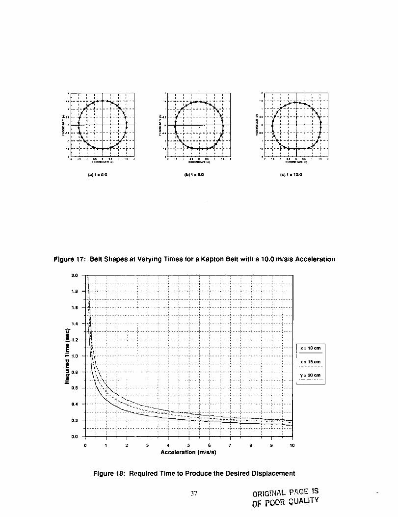
I I I
.... -:-- _-,I I I
I I I
_,, -,,-;--
_ ' ,I I
°i , ,_lI I
I I *
2.1 .11 .i 41 ol
x C(X3RDINA TE (mI
i i i
.-_-- -L-i
Illi
II"-T--I--
Ill
I I
It
ill
,s
_as
I
+s
I I I I I I
I I I I I I
] i i = L
j .... [I I I I
- _,-f-l'- -_-'--_-
.--,-'-':_"_-_........ ' r"I I I I I I
_s , el oi _s
i C_lllgt _ Ira)
_s
1
_o,!o
!'i
l I I I II I I I I I
I I I I I I
• _s _ 4s os 1 _s
x COQRO_NA I_ 1_}
(a) t = o,o (b) t = S,O (c) t = I0.0
Figure 17: Belt Shapes at Varying Times for a Kapton Belt with a 10.0 m/sis Acceleration
2.0
1.8
1.6
1.4
O
_- 1.o
_. 0.8Q
1£
0.6
0.4
0.2
0.0
., ..._. ...... _ ..... _ ..... _ .... : ....... _ ..... : ..... _ ...... _ ..... : ..... . ...... . ..... : ..... . ...... . ..... : ..... ; ..... _, ...... : .....
-I.--i......i .....!.....!....!......!.....!.....!......!.....i.....!......i.....!.....!......i .....!.....i.....i......!....._i...i......i .....:......i.... i......i .....:.....i......i .....i ....._......i .....i.....i......i .....i.....i .....i ......i ......t..i......_.....i.....i....i.....i.....i.....i......i.....i.....i......i.....i....i......_.....i.....i....._......i.....',t_ ::
-",!'-i......f .....i .....!:.... ]......i .....::.....]......f.....i .....]......i .....i....._......f .....i .....i.....]......_.....-_t"i ......_.....i ....._..... _......._.....i ....._......!.....i .....i......_.....i.....i......_.....i .....i.....i......_.....- . '_.-_...... i...... i ..... i ..... i....... i ..... i ..... -...... _..... i ..... _...... - ..... i .... i ...... i...... i ..... i ...... !...... _.....
_._.i......i......i.....i....i.....i.....i.....i......i.....i.....i......i.....i....i......i......i.....i.....i......i.....-li_" +................. !.......... ! ................ iF.......... !!IT!...... ..... .... ............ ! !..... ............ ! ..... X_=__10 cm
-t_i ......::...... i.....i..... i......i .....i ......:......i .....+.....i......::......i.... i......::......i .....i......:.......i .....--._-;i......::...... :,.....i.... :..... _.....i ......i .... _.....i....._......::......;.... _......:......:,.....i......::......::..... ,:_scm
--..t,-t_,-...i...... _..... _..... i..... i..... i......i...... _..... +..... +......._-..... +.... _......i...... _..... _......!...... +......\!_\ : : : : : : : : : : ', : : : : : : : y = 20 cm
-----_',,-_-i......i .....!..... i......i .....!......]......i .....i.....i......i......i .... !......i......i .....i......::......i ........................_._ "..,:_...._..... i..... i...... i..... i..... J......i..... ;..... i...... L....._.... i......i...... , ..... i......i...... _.....
i\ <\.i i : i i i i i i i i i ] i i : ',
......]]]]!]_".!_ii"..... :"_'_<_ .... _......_.... i ....._......_.....i....._.......:....._.... _......._....._.....i.....i......i ........... i ...... i.... i - >-- b ::="<-:-.;.:- -_..... i ..... _...... _...... i ..... -:...... ._..... i .... i ...... ._..... _..... i ..... _...... _.....i i : : "+_- :'_-_. : : i i : i i i i i : :
::::::::::::::::::::::::::::::0 1 2 3 4 5 6 7 8 10
Acceleration (m/s/s)
Figure 18: Required Time to Produce the Desired Displacement
3"7 ORIG_N&L P_,GE !S
OF POOR_UALiTY
effects of a perturbed belt on the heat transfer characteristics can be measured. The operating
temperature of the liquid bath will depend on the working fluid, on the belt material, on the belt
surface emissivity, and on the placement within the shuttle bay.
If gallium were to be used as the working fluid then the operating temperature range would be in
the 310 K to 350 K range. The maximum temperature would depend on the amount of power
available during the thermal testing. The lower end of the temperature range would be dictated by
the melting point of the working fluid. It would be desirable to remain approximately 10 K above
the melting temperature of the working fluid to assure that the working fluid is liquid during the
testing. The belt speed would be determined by the power input, the belt surface emissivity, and
the desired IHX bath temperature. These calculations are outlined in Reference 3.
9.5 RETRACTION AND STORAGE
The sequence of retraction and stowing the test fixture after completion of the test is as follows:
• Disengage main drive system;
• Activate clamp at exit of storage box, thereby sealing the exit of the storage box;
• Engage rear rollers so that the belt is pushed into the storage box;
• Lock all rollers so that belt will not move during remainder of mission;
• Verify that the working fluid is in a solid state (use of a thermal control system is required
to solidify the working fluid which will provide additional assurance that the working fluid
does not leak out during the landing procedure).
The proposed deployment/retraction system could be used for multiple deployments and retractions,
but it is not envisioned that this will be done during this experiment. The storage of the belt will
be in a random fashion, but in a final version the belt should have a means by which it can be folded
up neatly within the storage box. Attention will have to be paid to the required pressure of the
rollers on the belt so that the belt can be pushed into the storage box.
10.0 PROGRAM PLAN
10.1 INTEGRATION REQUIREMENTS
The final location of the experiment aboard the shuttle would have to be negotiated with NASA
personnel and would depend on requirements for all the payload and the required mass distribution
for the payload. The optimum location would be at the center of the shuttle bay, this being in line
with the best field of view for the belt. The HH-M can accommodate this position but it is unlikely
that a complete payload would allow this position.
10.2 REQUIRED TASKS AND MANPOWER ESTIMATES
The major tasks and the predicted manpower estimates that will be required for the project outlined
in this document are listed in Table 5.
38
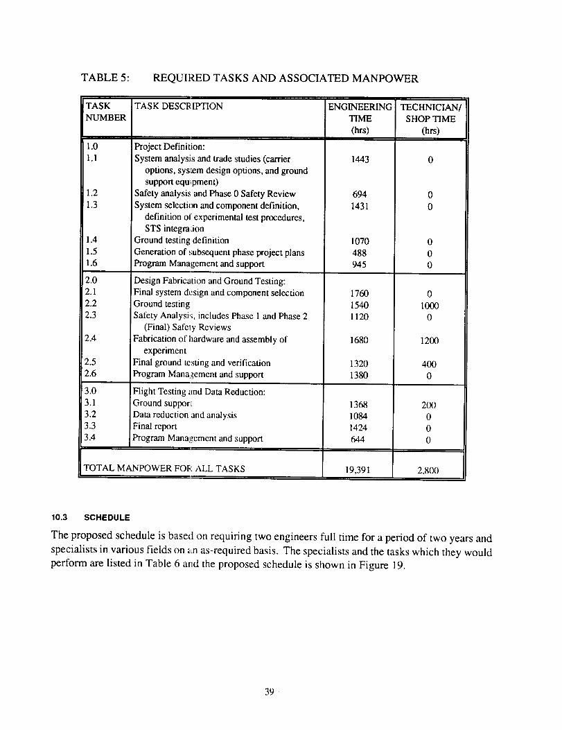
TABLE 5" REQUII:_D TASKS AND ASSOCIATED MANPOWER
TASK
NUMBER
1.0
1.1
1.2
1.3
1.4
1.5
1.6
2.0
2.1
2.2
2.3
2.4
2.5
2.6
3.0
3.1
3.2
3.3
3.4
TASK DESCRII:rHON
Project Definition:
System analysis and trade studies (carrier
options, system design options, and ground
support equ_pmen0
Safety analysis and Phase 0 Safety Review
System selection and component definition,
definition of experimental test procedures,
STS integm:ion
Ground testing definition
Generation of subsequent phase project plans
Program Management and support
Design Fabrication and Ground Testing:
Final system design and component selection
Ground testing
Safety Analysi:;, includes Phase 1 and Phase 2
(Final) Safely Reviews
Fabrication of hardware and assembly of
experiment
Final ground testing and verification
Program Management and support
Flight Testing and Data Reduction:
Ground suppor_
Data reduction and analysis
Final report
Program Management and support
TOTAL MANPOWER FOI;" ALL TASKS
ENGINEERING
TIME
(hrs)
1443
694
1431
1070
488
945
1760
1540
1120
1680
1320
1380
1368
1084
1424
644
19,391
TECHNICIAN/
SHOP TIME
(hrs)
0
0
0
0
1000
0
1200
400
0
200
0
0
0
2,800
10.3 SCHEDULE
The proposed schedule is based on requiring two engineers full time for a period of two years and
specialists in various fields on _Ln as-required basis. The specialists and the tasks which they would
perform are listed in Table 6 and the proposed schedule is shown in Figure 19.
39 ¸
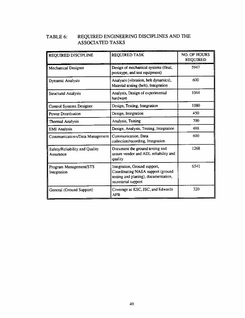
TABLE 6: REQUIREDENGINEERING DISCIPLINESAND THEASSOCIATED TASKS
REQUIRED DISCIPLINE
Mechanical Designer
Dynamic Analysis
Structural Analysis
Control Systems Designer
Power Distribution
REQUIRED TASK
Design of mechanical systems (final,
_rototype, and test equipment)
NO. OF HOURS
REQUIRED
5947
Analyses (vibration, belt dynamics), 600
Material testing (bei0, Integration
Analysis, Design of experimental 1044hardware
Design, Testing, Integration 1080
Design, Integration 450
'Thermal Analysis Analysis, Testing 700
EMI Analysis Design, Analysis, Testing, Integration 488
Communications/Data Management Communication, Data 600
collection/recording, Integration
1268Safety/Reliability and Quality
Assurance
Document the ground testing and
assure vendor and ADL reliability and
quality
Integration, Ground support,
Coordinating NASA support (ground
testing and planing), documentation,
secretarial support
Coverage at KSC, JSC, and EdwardsAFB
Program Management/STS
Integration
General (Ground Support)
6541
320
40
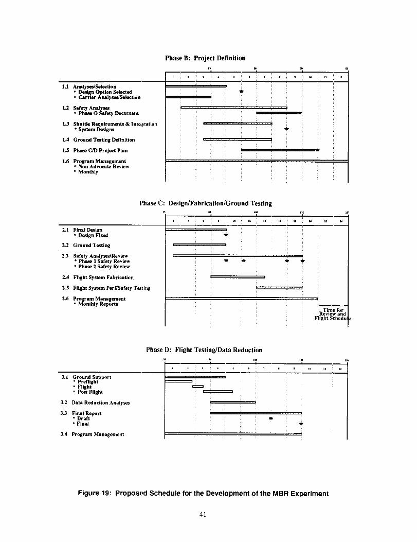
1.1 Analyses/Selection• Design Option Selected• Carrier Analyses/Selection
1.2 Safety Analyses
Phase B: Project Definition
i z : _ :i • | i _ :: |
i i i t
• ,' ' ' ' _ i,• Phase O Safety Document
1.3 Shuttle Requirements & Intel_ration• System Designs
1.4 Ground Testing Definition
1.$ Phase C/D Project Plan
1.6 Program Management• Non Advocate Review
• Monthly
m
! ,
i i . J ,,, , !
r
Phase C: Design/Fabrication/Ground Testing
", '72 i • 8 l* I1 n4
2.1 Final Design• Design Fixed
2.2 Ground Testing
2.3 Safety Analys_/Revlew• Phase I Safety Review• Phase 2 Safety Review
2.4 Flight System Fabrication
2.5 Flight System Perf/Safety T_ting
2.6 Pro_am Management• Monthly Reports
, |
u m
i
!
i la I¢
rT I
_:_Time for.: Kevlew ano
Flight Schedul
3.1 Ground Support• Preflight• Flight• Post Flight
3.2 Data Reduction Analyses
3.3 Final Report• Draft• Final
3.4 Program Management
Phase D: Flight Testing/Data Reduction
] a i _ 4 j t _
w m
'7
!
Figure 19: Propos_._d Schedule for the Development of the MBR Experiment
41
11.0 REFERENCES
The experimental design has just recently been initiated with preliminary results indicated in this
report. The background analyses leading to the development of MBR designs and understanding
of deployment and operational issues are contained in a series of reports prepared by ADL for
NASA Lewis. These reports are:
1. "Preliminary Evaluation of a Liquid Belt Radiator for Space Applications," NASA CR- 174807,
December, 1984.
2. Teagan, W.P. and Fitzgerald, K., "Liquid Belt Radiator Design Study," NASA CR-174901,
January, 1986.
3. "Moving Belt Radiator Technical Development, Final Report," to be published as NASA
CR-xxx, for NASA Contract NAS3-24650, 1990.
4. Aguilar, J.L., "Conceptual Design of MBR Shuttle-Attached Experiment, Technical
Requirements Document," NASA CR- 185168, 1989.
5. "The Simplified Space Payload Thermal Analyzer (SSPTA), Program Manual," Arthur D.
Little, NAS5-27606, October, 1986.
6. "STS Investigators Guide," Teledyne Brown Engineering under the direction of the Spacelab
Payload Project Office, Marshall Space Flight Center.
7. "Hitchhiker Shuttle Payload of Opportunity Carrier Customer Accommodations and
Requirements Specification," HHG-730-1503-04, Reissued July 1988, Preliminary Copy.
42

This page intentionally left blank.
PAGE.D(XZ l
National Aeronauhcs and
_ I)Ice AcIm_nlsl r &Iron
1. Report No.
NASA CR-185169
4. Title and Subtitle
Report Documentation Page
2, Government Accession No. 3. Recipient's Catalog No.
5. Report Date
June 1990Conceptual Design of MBR Shuttle-Attached Experiment
Final Report
7. Author(s)
Jerry L. Aguilar
9. Performing Organization Name and Address
Arthur D. Little, Inc.20 Acorn Park
Cambridge, MA 02140
12. Sponsoring A_ncy Name and Add_
NASA Lewis Research Center
6. Performing Organization Code
8. Performing Organization Report No.
10. Work Unit No.
506-48-4A
11. Contract or Grant No.
NAS3-25356
13. Type of Report and Period Covered
Contractor Report
Final
14. Sponsoring Agency Code
15. Supplementaw Not_
Project Manager, Alan White, Power Technology Division, Nasa Lewis Research Center
In-Space Experiments Focal Point, Olga Gonzales-Sanabria
16. Abstract
The conceptual design of a shuttle-attached Moving Belt Radiator (MBR) experiment
is presented. The MBR is an advanced radiator concept in which a rotating belt
is used to radiate thermal energy to space. The experiment is developed with the
primary focus being the verification of the dynamic characteristics of a rotating
belt with a secondary objective of proving the thermal and sealing aspects in a
reduced gravity, vacuum environment. The mechanical design, selection of the belt
material and working fluid, a preliminary test plan, and program plan are
presented. The strategy used for selecting the basic sizes and materials of the
components are discussed. Shuttle and crew member requirements are presented with
some options for increasing or decreasing the demands on the STS. An STS carrier
and the criteria used in the selection process are presented. The proposed
carrier for the Moving Belt Radiator experiment is the Hitchhiker-M. Safety
issues are also listed with possible results. This experiment is designed so
that a belt can be deployed, run at steady state conditions, run with dynamic
perturbations imposed, verify the operation of the interface heat exchanger and
seals, and finally be retracted into a stowed position for transport back to earth
17, Key Words (Suggested by Authors))
Moving Belt Radiator
Advanced Space Radiator
Space Power
Shuttle Experiment
18. Distribut_n Statement
Unclassified-Unlimitted
Subject Category 20
19. _curi_ Classif. (of this report) _. S_ud_ Cla_f. (of this page)
Unclassified Unclassified
21. No of pages
48
NASA FORM 1626 OCT 86 "For sate by the National Technical Information Service, Springfield, Virginia 22161
22, Price"
A03