conceptual design of a moving belt radiator shuttle-attached … · 2013-08-30 · nasa contractor...
TRANSCRIPT
NASA Contractor Report 185168
Conceptual Design of a Moving Belt RadiatorShuttle-Attached Experiment
Technical Requirements Document
Jerry L. Aguilar
Arthur D. Little, Inc.
November 1989
Prepared forLewis Research Center
Under Contract NAS3-25356
NASANational Aeronautics and
Space Administration
(_A,__A-C -16ql 6_3) CqNCEPTUAL DESI n,N OF A
MgVING _ELT RADIATJR SHUTTLE-ATTACHEO
! EXP_RIHF_NT3: TECH_,ICAL REQUIREMFNT DUCU MENT
i (Little (Art|Pug O.)) 63 p CSCL I0_
I_ , I'I UI" '=,
N90- 1.5 q'_5
Uncl as
G31ZO 0260745
1
https://ntrs.nasa.gov/search.jsp?R=19900006680 2020-04-21T10:01:27+00:00Z

_ . _ ±_ _i _I _i_
NASA Contractor Report 185168
Conceptual Design of a Moving Belt RadiatorShuttle-Attached Experiment
Technical Requirements Document
Jerry L. Aguilar
Arthur D. Little, Inc.
November 1989
Prepared forLewis Research Center
Under Contract NAS3-25356
NASANational Aeronautics and
Space Administration
Artlur D Little

TABLE OF CONTENTS
1.0 SUMMARY ........................................................................................................................... I
2.0 INTRODUCTION ................................................................................................................. 22.1 BACKGROUND ............................................................................................................. 22.2 JUSTIFICATION FOR SPACE SHUTTLE TESTING ................................................. 32.3 DEPLOYMENT .............................................................................................................. 42.4 DYNAMIC ANALYSIS ................................................................................................. 52.5 THERMAL ANALYSIS ................................................................................................. 5
3.0 OBJECTIVES AND SCOPE ................................................................................................. 6
4.0 RELATIONSHIP TO NASA MISSIONS ............................................................................. 7
5.0 TECHNOLOGY BENEFITS ................................................................................................. 8
6.0 RELATIONSHIP TO OTHER AGENCIES AND CENTERS ............................................. 8
7.0 TECHNICAL DESCRIPTION .............................................................................................. 97.1 SYSTEM DESCRIPTION .............................................................................................. 97.2 EXPERIMENT SEQUENCE .......................................................................................... 117.3 REQUIRED MEASUREMENTS ................................................................................... 127.4 DATA COLLECTION AND REDUCTION .................................................................. 12
8.0 PAYLOAD INTEGRATION ................................................................................................ 138.1 TECHNICAL REQUIREMENTS ................................................................................... 138.2 REQUIRED POWER ...................................................................................................... 138.3 REQUIRED SUPERVISION .......................................................................................... 158.4 ORBIT REQUIREMENTS ............................................................................................. 15
9.0 SUPPORTING DATA/REFERENCES ................................................................................. 15
APPENDIX A ................................................................................................................................ 16A. 1 STEADY-STATE MOTION_ .......................................................................................... 16A.2 DYNAMIC RESPONSE ISSUES_ .................................................................................. 17A.3 DYNAMIC MODEL OF IN-PLANE MOTION ........................................................... 21A.4 COMPUTER PROGRAM SUMMARY ........................................................................ 25
APPENDIX B ................................................................................................................................ 27B.1 RADIATIVE HEAT TRANSFER EQUATIONS .......................................................... 27B.2 MBR GEOMETRICAL RELATIONSHIPS .................................................................. 28B.3 BELT SPEED DETERMINATION ............................................................................... 31B.4 INTERFACE HEAT EXCHANGER SIZING ............................................................... 31B.5 PARASITIC POWER LOSSES ..................................................................................... 32B.6 ORBITAL AERODYNAMIC DRAG ............................................................................ 33B.7 REFERENCES TO APPENDIX B ................................................................................. 34
APPENDIX C ................................................................................................................................ 35
FIGURES ....................................................................................................................................... 37
PRECEDING PAGE BLANK NOT FILMED
• t
e -.ZL-.JN (nrloj BtJ

i
z
1.0 SUMMARY
This document describes a proposed experiment which will demonstrate the dynamic and thermal
characteristics of a Moving Belt Radiator. This type of radiator, along with the Liquid Droplet and
Rotating Bubble Membrane Radiators, are classified as advanced concepts currently under devel-
opment. The Moving Belt Radiator is predicted to have a weight one fifth to one third that of the
current baseline heat pipe system in addition to higher survivability, options for retraction, better
maneuverability, and extremely high heat rejection levels (5 to 200 MW). This level of heat rejection
would permit many missions and technologies currently being considered. These would include
use of nuclear power in space, Mars transfer mission, manned space platforms, and burst power
systems.
The moving belt radiator system is one in which the waste energy from a spacecraft, space station,
or satellite, is transported to the belt (a closed hoop) via an interface heat exchanger. In this heat
exchanger, a fluid bath provides a direct path for the energy to transfer to the belt. The belt is drawn
through the bath and then exposed to space, where the energy is radiated out. Various concepts
have been considered for the belt, including a mesh structure in which fluid menisci are formed on
the belt and become the radiating surface, and a belt which encases a phase change material storing
the thermal energy. The shape of all belts is assumed to be the same, a cylindrical hoop. The shape
is attained through the use of centrifugal forces of a rotating belt, i.e. with no other forces dominating,
the centrifugal forces will cause the belt to stretch until a taut hoop is formed. The speed and
material properties will determine how stiff a hoop is ultimately formed.
Arthur D. Little, Inc. has been developing the Moving Belt Radiator concept with the NASA Lewis
Research Center. During the past few years various studies and laboratory experiments have been
conducted at Arthur D. Little. These include dynamic analysis and testing, heat exchanger sealing,
measurement of candidate belt material properties, and wettability testing of candidate workingfluids.
The most recent experiment was a test of the dynamic characteristics aboard the NASA KC-135
research aircraft in which it was demonstrated that, in a reduced gravity environment, the belt would
form a hoop under certain conditions. Also, it was shown that the belt would form a hoop after
being deployed from a stowed configuration, and that after a perturbation the belt would deform
and then return to the original shape. One more series of flights is scheduled for early 1990, in
which new belt materials will be tested. Further experimentation is required with larger belts and
in an environment free from air currents, KC-135 vibrations, and variable gravity levels. Thermal
testing must also be included. The thermal testing could be accomplished in vacuum chambers but
the dynamic testing requires a space based platform. The KC- 135 cannot accommodate larger belts
than have already been tested and no simultaneous dynamic and thermal testing is possible unless
a large vacuum chamber is installed in the KC-135. It is therefore necessary to develop a shuttle
flight experiment which would allow an integrated test to be conducted.
The primary focusof the spaceflight experimentshouldbe the verificationof dynamiccharac-teristics. A thermaltestcould be integratedinto theapparatussuchthata working versionof aMovingBelt Radiator could be demonstrated. An added feature of the proposed experiment is that
retraction of the belt would be demonstrated.
The belt would be between 2.4 m and 3.7 m (8 ft. and 12 ft.) diameter, which is at least twice the
size of the article tested on the KC-135. The physical integration of the experiment into a shuttle
payloadwould be relatively straightforward. The experiment would be located on the Hitchhiker-M
carder in the shuttle bay, i _
The requirements for an experiment of this type would include a minimum of two hours of testing,
orienting the shuttle bay away from the sun for thermal testing, and approximately 1500 W of
power. The required supervision w0uldq_e minimal and no extravehicular activity or remote
manipulator system use would be necessary.
2.0 INTRODUCTION
2.1 BACKGROUND
As part of ongoing work with NASA Lewis Research Center since 1982, Arthur D. Little, Inc.
(ADL) has been developing the Moving Belt Radiator (MBR) concept for use on spacecraft. In
this concept, shown in Figure 1, a belt is drawn through an interface heat exchanger (IHX) containing
a low vapor pressure working fluid which functions as the heat sink for the power generation or
environmental conditioning system. The moving belt passes through the IHX where it is heated
by the hot fluid; then as the belt travels through space it radiates the energy to the background
environment. This effort initially focussed on liquid belt radiators (LBR) wherein a meniscus of
the IHX fluid formed on a mesh structure, the belt. This concept resulted in excellent heat transfer
characteristics in the IHX and could take advantage of the heat of fusion of the IHX liquid (tin,
lithium, etc.). Recently, increased attention has been focussed on a unique hybrid belt radiator
(HBR) design which retains the excellent heat transfer characteristics of the LBR in the IHX but
does not result in a free liquid surface exposed to space.
This work, described in References 1 - 3, shows that appropriate MBR configurations have major
advantages for use in space missions with substantial heat rejection requirements including:
• An ability to stow 200 MW radiators in the shuttle bay;
• Relatively simple deployment from a stowed position;
• Weight of one fifth to one third that of heat pipe or pumped fluid configurations;
• Favorable survivability characteristics against both natural environment and hostile threats.
These attributes could both enhance and enable future NASA and Department of Defense (DOD)
missions as their thermal heat rejection needs increase over the coming decades.
In order to verify the basic dynamic characteristics of a MBR, a 1.2 m (4 ft.) belt was tested aboard
the KC-135 test bed in April of i989. This test only addressed the dynamics of the belt with no
testing of the heat transfer system. The data that was collected is primarily in the form of video
and 16 mm film. Preliminary results confirm that some belts do form a cylindrical shape in a reduced
gravityenvironmentwhendrivenin acircularfashion. Furtherinvestigationwill beconductedinorderto determinewhy somebeltsdid not form cylindrical shapes.From this seriesof tests,themajorcharacteristicsdemonstratedwere:
• Beltsmadefrom thepropermaterialandthicknesswill form a hoop;
• Belts,whenstowed,canbedeployedandwill assumeacylindrical shape;
• Beltswhicharenot movingcanbestartedin reducedgravityandwill form ahoop.A secondseriesof KC-135testsis scheduledfor early in 1990. This secondseriesof testswillendeavorto providemoredataon specificbelt characteristicswhich arefavorableto MBR appli-cations.
2.2 JUSTIFICATION FOR SPACE SHUTTLE TESTING
This document describes the essential features of a space flight experiment which can verify essential
dynamic and thermal characteristics of a MBR system during deployment and operation, thereby
allowing for refinement of the analytical projections of the overall MBR performance. A comparison
of MBR performance with alternative radiator concepts can then be performed for advanced mis-
sions having substantial heat rejection requirements.
A small scale MBR has been tested on two KC-135 flights in April 1989. On these KC-135 flights
reduced-g can be achieved for approximately 20 seconds. For small and relatively stiff belts,
verification of the dynamic characteristics can be accomplished on the KC- 135. If larger and more
flexible belts are to be tested, then extended time in reduced-g is required. This can only be achieved
in a space flight experiment. Also, this experiment will provide an environment in which to test
the dynamics with no influence from earth's atmosphere, i.e. no air induced perturbations. As with
any thin and flexible material, an air gust could influence the shape of the belt. In a KC- 135 flight,
the actual period of reduced-g varies from parabola to parabola. During the 20 second parabola, a
reduced gravity environment of varying g-level is provided. The gravity field can vary from +0.1
g to -0.1 g. Past dynamic analysis of belts has predicted that these acceleration levels can be too
high for some belts, which was evident in the first series of KC- 135 flights.
One of the key issues now requiring resolution as part of an overall program is to verify exper-
imentally, in a reduced-g environment, the dynamic characteristics during deployment and oper-
ation, thus providing a basis for comparison of these characteristics with analytical projections.
Only limited information can be generated experimentally using ground based facilities for the
required reduced-g test due to inherent time limitations imposed by such facilities (maximum of
20 seconds). Confirmation of dynamic characteristics will, therefore, require a larger test bed and
longer term testing in a space environment.
The dynamic characteristics that should be examined during a space flight experiment are:
• Deployment to a cylindrical shape with no support structure;
• Required deployment time;
• Required time to damp out perturbations;
• Allowable acceleration levels;
• Retractioncapability.
Additionally,a spaceflight experimentwill allow thethermalcharacteristicsto be testedin aspaceenvironment.TheIHX will befilled with theworkingfluid andadditionaldatawill begainedfromtestingaworkingmodelof aMBR. Theoptionto removetheworking fluid from theexperiment,therebyeliminatingthethermaltesting,canbeexercisedatany time. Thisdocumentwill, however,describeanexperimentwhictiwill includetheWorkingfluid andthermaltesting.Thethermalcharacteristicsthat-will beexaminedin thespaceflight experimentare:
• Theproposedsealingapparatus;• Theheattransfercharacteristics;
• Thevaporizationrateof theworking fluid.
The informationgainedin the KC-135flights is a goodbaseon which to build. The additionaltesting that can only be accomplishedin a longer durationmicrogravity environment will beextremelyvaluableto the progressof MBR technology. The proposedshuttleexperimentwill,therefore,provideuswith theablqitytotest-a-beltsuchthat:
• No influencefrom air currentsispresent;• KC-135 variablegravity levelsareeliminated;
• Belt diametersbetween2.4and3.7meters(8 to 12feet)arepossible;
• A very flexible beltwhich requiresmorethan20secondsto dampout perturbationscanbeexamined;
• A completeworking modelof aMBR canbedemonstrated.
2.3 DEPLOYMENT
Several modes of MBR deployment have been assessed and their impacts on stowability, deploy-
ment, and system weight evaluated. These include:
• Using lightweight, extendable, boom structures to establish the shape and movement of
the belt.
• Taking advantage of the zero gravity environment and centrifugal forces such that the belt
can self deploy into a hoop structure (Figure 1).
Previous work at ADL has indicated that both approaches result in attractive mechanical, thermal,
and weight characteristics (Reference 1). The self deployed option, however, has the potential for
very low weight by virtue of eliminating the need for structural deployment components. However,
this option produces a complex dynamic system which must be analyzed and tested.
4
2.4 DYNAMIC ANALYSIS
The dynamics of the MBR are complex, particularly during deployment and when perturbed by
short or long term acceleration fields. In recognition of this, ADL has developed a unique computer
modeling program referred to as BERS, which allows for the dynamic analyses of such "floppy
structures" as a function of their physical characteristics and imposed force fields. This model uses
a lumped-parameter representation of the MBR structure. The formulation of the equations of
motion and the interactions between the nodes are described in Appendix A. The results of this
model indicate that:
• The equilibrium shape of the MBR structure is a hoop with the stiffness determined by
belt materials, physical dimensions, and angular velocity.
• A short term physical disturbance, such as that resulting from a docking maneuver, should
dampen out after a few belt revolutions. See Figure 2 for a sample plot of the projected
shape during the short term acceleration.
• Under sustained acceleration fields the belt will elongate in shape and eventually become
inoperative. The allowable duration of such accelerations will depend on the magnitude
of the acceleration and the characteristics of the belt. See Figure 3 for a sample plot of the
projected shape during an extended acceleration.
• Increased angular velocity increases stiffness and reduces susceptibility to gross defor-
mation.
The experimental design will endeavor to allow verification of these characteristics.
2.5 THERMAL ANALYSIS
A parametric study of the thermal characteristics of possible MBR systems was performed and is
covered extensively in References 1 and 2. Reference 3 details ground based thermal testing that
was performed at ADL. Appendices B and C contain the development of the equations required to
complete the parametric studies. Following is a brief description of the assumptions, procedures,
and results of the thermal analysis.
Thermal characteristics were developed for all types of belt radiator systems, namely the LBR,
HBR, and MBR. The calculation of radiation heat transfer characteristics are similar for all three
systems, with a very important consideration being the view factor; Appendix B describes the
development of the view factor equations.
The emissivities will vary with each type of belt system. The LBR, which has a liquid exposed to
space, can have a relatively high emissivity if certain oils are used. Emissivities up to 0.8 can be
achieved for moderate and low temperatures. For higher temperature applications, liquid metals
are prime candidates for the working fluid. The drawback of liquid metals is that the emissivities
are much lower, on the order of 0.1. With the HBR (phase change material encased in a belt) and
the MBR (no liquid except in the IHX) the emissivity is a function of the belt material. With the
solidbelt systemthebelt canbedesignedto beanearperfectblackbody(emissivityof 1.0). Thehighertheemissivity,thesmallertherequiredareafor agivenheatloadwhich isanotheradvantagefor this typeof system.Practicalemissivitieswouldbe in 0.8to 1.0range.Theequationsandmethodologyusedtoanalyzeabeltsystemaredescribedin AppendixC. AlthoughtheinformationinAppendixCwaswrittenspecificallyforthe75kW pointdesignstudyof Reference2, theequationscanbeappliedto anybelt radiatorsystem.
3.0 OBJECTIVES AND SCOPE
The overall objective of this program is to design a space flight experiment which would:
• Demonstrate that the belt radiator can be deployed from a stowedposition and will assume
the shape indicated in Figure 1 within a reduced-g environment;
• Measure belt dynamic response to low level acceleration fields and to impulse forces which
might result from a docking maneuver or other sudden change in spacecraft position;
• Verify the computer dynamic models used to predict belt motion as a function of belt
physical parameters, operating parameters, and spacecraft motion;
• Verify the predicted thermal characteristics of the MBR;
• Demonstrate retraction capabilities of a MBR system.
The flight experiment will be designed under conditions of belt speed, belt physical parameters,
etc. which are consistent with those that would be used in full size working radiator systems. This
is in contrast to the ground based reduced-g experiments where belt speeds and dimensions have
to be adjusted to provide meaningful responses in the limited time periods allowed by the test
facilities (2 to 25 seconds).
The flight experiment will be designed such that dimensions and belt dynamic characteristics are
scaled equally. Some of the important items to be scaled are:
• DimenSions of the belt and IHX;
• Mass of belt and IHX;
• Damping properties of the system;
• Stiffness properties of the system.
The experimental apparatus will be designed to allow a high level of flexibility in the range of
experiments to be conducted, i.e., to allow variation in operating conditions during the experiment.
The experimental design and associated data acquisition will be consistent with safe operation on
one of the space shuttle experimental test beds.
A functioning MBR will require a low vapor pressure liquid (gallium being the prime candidate)
in the IHX. If no technical or safety issues preclude the use of an IHX liquid, then it would be
desirable to include this capability in the experiment. Insight into the thermal characteristics would
be gained as well as verification of seal performance in reduced-g and vacuum. A sealing system
must be designed and tested in order to assure that no working fluid will contaminate any other
experiment or the shuttle itself. Ground testing will be conducted in order to verify that the seals
will withstandthevibration,thermal,andvacuumenvironmentsthatarepresentin low earthorbitandduringshuttleascentanddecent.Thesealingarrangementwill allow for redundancy;in theeventthatonesealfalls,aback-upwill maintainoverallintegrity. Theexpectedvolumeof workingfluid is approximatelyoneliter. Theproposedgroundtestsinclude:
• Vacuumchambertests;
• Vibration tests;• Thermalshocktests.
Theverificationof thedynamiccharacteristicswill beof primeimportanceandthethermalchar-acteristicsof secondaryimportance.The thermaltestingcanbeeliminatedfrom thedesignat anytime without delayingthe work on theMBR experiment. Also, the working fluid will be in aseparatecontainerandneedneverbeintroducedinto theIHX if apossibledangerarisesduring theflight.
4.0 RELATIONSHIP TO NASA MISSIONS
Many types of missions would potentially benefit from an MBR, such as NASA and DOD missions
which require:
• Burst power: During low power consumption periods the MBR could dissipate any excess
power.
• Storage of cryogenic fuels: Using an MBR system the cryogenic fuels could be maintained
at very low temperatures.
• High maneuverability: The relative ease with which an MBR can be deployed allows high
maneuverability missions to be considered. Two methods can be employed during
maneuvers: retract the MBR and redeploy when the maneuver is completed; or limit the
maneuver accelerations such that the belt will not fail.
For certain DOD missions, a large area conventional radiator would be an inviting target for hostile
threats. The MBR may be less susceptible to such threats since puncture of the belt surface would
not necessarily impair overall MBR operation.
The MBR has many of the weight and deployability attributes of the Liquid Droplet Radiator (LDR)
also under development for similar applications. For this class of radiator, major weight and
deployment advantages exist in applications such as:
• Orbital Transfer Vehicles (OTV) using a nuclear Brayton cycle power system to generate
10 MW of electric power;
• 100 kW nuclear Stirling engine power systems;
• Manned space platforms and growth versions of the space station;
• Laser platforms and particle beam vehicles;
• Space based radar;
• Mars transfer vehicle;
• Certain SP-100 and multimegawatt space power platforms.
SuccessfulMBR developmentwould, therefore,eitherenhanceor enableabroadrangeof NASAand DOD missions. In particular, missionswith relatively large heat rejection requirements(>200kW)canbeenhancedsignificantly,particularlywhenthestowedvolumeof aheatpiperadiatorsystembecomessubstantial.
5.0 TECHNOLOGY BENEFITS
Although of simpledesign, the space fl_gh_experiment which will be developed during this program
will have major benefits to the development of advanced radiator systems and to the broader issue
of Understanding the dynamic characten_stics of "floppy" space structures. Specific benefits Will
include:
• Verification of critical elements of MBR dynamic characteristics, which will allow con-
tinued development of this concept with a high level of confidence that the constraints
imposed by dynamic considerations are well understood;
• Refinement of dynamic models used to project the dynamic characteristics of MBR systems
both in normal operational modes and when subjected to acceleration fields. Theseimproved models will make it possible to design a more reliable and effective advanced
radiator system and determine constraints on spacecraft motion;
• Improvedunderstanding of the dynamic characteristics of the whole category of "floppy"
structures. Understanding of the dynamics of these "floppy" structures will be required to
implement a broad range of advanced radiator systems (LDR, etc.) and solar collector
systems with large lightweight area requirements;
• Improved understanding of sealing specific fluids in a space environment. This is also
applicable to other advanced radiator concepts:.
In short, the space experiment is a key step in the development of MBR systems. Such systems
show particularly g_d:potential, resulting in stowable,lightweight radiators required for future
NASA and DOD missions having substantial power requirements.
6.0 RELATIONSHIP TO OTHER AGENCIES AND CENTERS
The work on the MBR is part of a comprehensive investigation of advanced radiator systems.
Various NASA centers such as Lewis, Johnson Space Center (JSC), and Goddard Space Flight
Center (GSFC), are managing the research in these new technologies. NASA, in cooperation wlth
the DOD, is coordinating the direction of research which is best suited for possible future missions.
The main DOD centers which are interested in advanced radiator systems include the Air Force
Astronautics Lab (AFAL) and Air Force Wright Aeronautical Labs (AFWAL) at Wright Patterson
AFB. Currently the NASA effort is dividedas follows:
• Lewis is involved with advanced heat pipes, LDR, and the MBR technologies;
• JSC is involved with advanced heat pipes, advanced heat exchangers (evaporators, con-
densers), two phase pumped loops, and the Rotating Bubble Membrane Radiator (RBMR)
concept;
• Goddardprimarily is involvedwithadvancedheatexchangersandtwophasepumpedloops.
With NASA investigatingthepossibleoptionsfor futurespaceradiatorconceptssuchastheMBR,LDR,andtheRBMR,manysimilartechnicalobstaclesexistandadvancementwith anyoneconceptcouldalsobenefittheothers,TheMBR spaceflight experimentrelatesdirectlyto otherprogramswithin NASA, DOD, industry,andacademiadirectedtowardthedevelopmentof advancedradiatortechnologies.Theseinter-relationshipsinclude:
• The participationof multiple NASA centersand the OAST Office in establishingtheinterfaceandsafetycriteriawhichwill guidethedesignof theexperiment.
• Inclusion of the experienceof DOD programsdirectedtoward MBR applicationsasexemplifiedby theseveralMBR developmentefforts sponsoredby AFAL.
• Disseminationof experimentalresultsto companiesassessingthepotentialfor advancedradiatorsto enablefuturecivilian andmilitary missions.
• Thedevelopmentof adatabaseallowing for improvementof theanalyticalmethodsforpredictingthedynamicresponseof "floppy" structuresoperatingin aspaceenvironment.Suchacapabilityis centralto theevaluationanddesignof largespacestructuresin generalandspecificallyfor severalof theadvancedradiatorconceptsunderconsideration.
Dueto theinterestof thespacecommunityin thisandrelatedtechnology,theprogramparticipantswill endeavorto ensurethattheexperimentaldesignis consistentwith hardwarethat will addressmostof thekey issuesassociatedwith dynamiccharacteristicsof this technology.
7.0 TECHNICAL DESCRIPTION
7.1 SYSTEM DESCRIPTION
A preliminary design of the basic experimental apparatus is shown in Figures 4, 5, and 6. The
components which have been identified to date are:
• An IHX with the working fluid and the required seals;
• A reservoir which will contain the working fluid during transport to low earth orbit;
• A belt made of a polymeric material which will be drawn through the IHX; the belt will
be between 2.4 and 3.7 meters (8 and 12 feet) in diameter, depending on spacecraft inte-
gration requirements;
• A motor-roller arrangement which will drive the belt;
• A load cell system which will measure the forces produced by the belt and the IHX on the
simulated spacecraft;
• A linear actuator which can perturb the belt so as to simulate a docking maneuver or other
short term acceleration;
• A camera system which will allow photographic documentation of belt motion during
deployment, normal operation, and when subjected to linear perturbations;
• A deploymentmechanismwhichwill form thebelt intoaroughlycylindrical shapebeforeengagingthebelt drive system;
• A retractionsystemwhichwill stowthebelt aftertestingis completed.The list of the components must be expanded and specific items identified. Most of the components
will be selected due to their survivability, reliability, and the space constraints dictated by the shuttle
mission. Following are some of the considerations for the primary components.
• Belt Material: The belt must be chosen such that the dynamic response will be similar to
that of a full size syste m. The material having the bes t thermal characteristics and com-
patibility with the space environment will be sought. Some possible belt materials include
nylon, polyimides, Teflon, polypropylene, polyethylene, mylar, tantalum, and aluminum.
• Seals for the IHX: The seals that wiqlbe used should be similar to those used in previous
bench-top testing (see Reference 3). The seals should be compatible with the space
environment and the working fluid. Some possible seal materials include: rulon, Teflon,
or some type of elastomeric compound.
• Working Fluid: A low vapor pressure fluid with relatively high thermal conductivity is
essential. If the fluid is nonwetting and has high surface tension, then the seal design is
simplified. Gallium meets the requirements and is, therefore, a prime candidate. Other
liquids, such as mercury, will be examined for applicability to this experiment.
• Drive System: The drive motor and rollers must all be chosen based on weight, compat-
ibility to the space environment, and performance in a MBR system. Reliability of the
components must be extremely high to ensure proper operation over extended periods of
operation and multiple starts and stops.
• Deployment and Retraction Mechanism: The criteria for this system are similar to that of
the drive system.
• LinearPerturbati0n System: This will be comprised of multiple linear actuators which will
have the power to accelerate the MBR to the required levels. Also, the distance that the
linear actuator can displace the MBR must be sufficient to accurately model the predicted
displacements that would occur in a final design, on the order of 5 to 15 cm (2 to 6 inches).
The reliability must again be very high. Also, consideration will be given to the influence
that the linear actuators have on the dynamic behavior of the overall MBR system.
• Measurement Equipment: Redundancy will be employed but a high reliability will still be
expected of this equipment. Compatibility with the space environment and the capacity
to measure the expected loads will be prime considerations. All of the equipment should
be able to handle some overload due to unexpected influences, including those from shuttle
launch. The effects that any measurement device has on the MBR operation should be
minimized or eliminated.
10
All of the equipment that is selected must be able to withstand the accelerations due to shuttle take
off. These are not trivial and must be accounted for both in the equipment and in the structural
integrity of the experiment. In addition to these considerations, safety and weight will influence
all component selections.
Operating temperatures for the linear actuators and drive system will be an important factor in
deciding whether or not a heating/cooling system is required in order to maintain proper operating
temperature during this experiment.
7.2 EXPERIMENT SEQUENCE
The sequence that will lead to a successful experiment is as follows:
• Deployment of Belt: When the MBR experiment is ready for operation the deployment
system will be actuated, allowing the belt to form a cylindrical shape due to the centrifugal
forces. The deployment of the belt will require that the motor to the storage drive rollers
be disconnected via a clutch; the main drive motor will then pull the belt out of the storage
box and through the IHX, feeding it out to space. This would allow the belt to deploy into
a cylindrical shape.
• Operation of the MBR: The belt will be operated in its normal deployed shape for an
extended period of time, the duration depending on overall mission requirements. During
this period the belt speed and IHX seal forces will be varied over a predetermined range
to verify the effects of these operating parameters on belt dynamics.
• Linear Perturbations: Once steady state dynamic characteristics have been measured, the
actuator will move through a preestabl!shed sequence to verify belt dynamic response when
subjected to linear accelerations. A range of both displacements and acceleration levels
will be explored in order to test the capabilities of the analytical models to accurately assess
the impact of imposed motion. The photographic record of the belt dynamics will be
particularly important during this experimental sequence.
• Thermal Testing: Thermal characteristics of the MBR would then be measured. The IHX
would be filled with the working fluid and the belt would be operated under a steady state
condition for a variety of gallium bath temperatures, belt speeds, etc.
• The final steps would include retracting the belt and securing the experiment for the return
to earth. The retraction of the belt would require (refer to Figure 5) that the main drive
motor be switched off and that the solenoid clamping system at the exit of the storage box
be activated, thereby sealing the storage box. The motor connected to the storage drive
rollers would then be activated and engaged via the clutch and the belt would be fed into
the storage box. No internal mechanism for storing the belt in an orderly fashion is planned
for the shuttle experiment; therefore, the belt would stow away in a random fashion.
11
7.3 REQUIRED MEASUREMENTS
The measurements that are required will fall into two categories: 1. Control and maintenance; 2.
Data collection. In the area of control and maintenance the quantities to be measured will include,
but not be limited to:
• Belt velocity;
• Deployment mechanism position;
• Torque output of belt drive system;
• Gallium bath temperature;
• Power input into the gallium bath, i.e. current into the electrical resistance heating, IHX
wall temperature (solar load), etc.
As data collection measurements, a variety of forces and accelerations must be monitored, as well
as some thermal characteristics. These will include:
• Belt temperature at entrance and exit of IHX;
• Belt motion and shape;
• IHX impulse acceleration levels;
• Reaction forces on the simulated spacecraft;
• Belt drag forces due to IHX.
An instrument tape recorder may be required due to the large volume of data, especially during
thermal testing. If possible, the shuttle recording capabilities will be utilized.
7.4 DATA COLLECTION AND REDUCTION
The data collected from the experimental apparatus of Figure 5 will be:
• Verification of belt shape in the reduced gravity environment when subjected to linear
motion. (Photographic documentation)
• Drag forces on the IHX and associated parasitic power due to seal pressure and variable
forces during normal operation. (Load cell)
• Force fields on the IHX due to short-term linear accelerations. (Load cell)
• Damping coefficients of belt pe_urbations resulting from impulse linear acceleration.
(Photographic documentation and accelerometers)
• Thermal characteristics of the MBR. (Thermistors)
This information will be compared to: analytical predictions (Reference 3) from alumped parameter
model which simulates belt dynamics; the projections of seal forces (parasitic power losses) as
estimated by basic mechanical analyses of the functioning IHX; the thermal analysis; and ground
based thermal testing.
12
8.0 PAYLOAD INTEGRATION
8.1 TECHNICAL REQUIREMENTS
The proposed experiment is to be conducted in the shuttle bay. This would allow for the use of a
pallet, hitchhiker carrier, or spacelab module as the experiment carrier. Figure 7 shows a possible
mounting configuration within the shuttle using the Hitchhiker-M platform.
The deployment of the experiment within the shuttle bay area will allow a larger belt to be tested.
Figure 8 shows the deployed unit in the shuttle bay. The radiator surface should view space with
minimal incident solar energy. In order to have the maximum view of space, the entire radiator
surface should be above the shuttle bay doors. The view factor for the belt will have to be calculated
once the elevation above the shuttle opening is known.
It is expected that at least two hours will be required to conduct a comprehensive test. The testshould include as a minimum:
• Extended periods in steady state operation at various conditions (operating time of
approximately 30 minutes);
• Periods of perturbation and return to steady state (operating time of approximately 1 hour);
• Thermal testing at various power levels (operating time of approximately 1 hour).
In addition to these phases of testing, a deployment and retraction sequence will have to be per-
formed. These two steps should not require more than ten minutes total. Finalization of the test
plan and required time must be negotiated with NASA personnel.
The expected mass of the experiment is detailed in Table 1. Two estimates are listed in Table 1,
one for a system which will test a 3 m (10 ft.) diameter belt, and a second for a 3.7 m (12 ft.) diameter
belt.
8.2 REQUIRED POWER
Table 2 lists the expected power requirements. The majority of the power will be used to drive the
belt. This parasitic power in the system is due to the drag forces within the IHX, and to a lesser
extent, the drag forces of the rollers. The highest level of power during the dynamic testing will
be associated with the deployment of the belt. It is at this time that all drag forces will be present
as well as the requirement to accelerate the belt to speed.
A specific temperature (approximately 320 K) will be required within the bath so that evaluation
of the thermal characteristics can be achieved. One option for heat input would be to use an electrical
resistance heating element in the bath with a control system. Another possible option is the use of
solar heating as the power input for the gallium bath, thereby reducing the requirement for onboard
power. The power required for electrical resistance heating is relatively high and may require
additional battery packs. The most straightforward approach would be to use shuttle power with,
if required, additional battery packs. The belt material will have to be chosen (proper emissivity)
13
TABLE 1"
Item
MASS OF PROPOSED EXPERIMENT "
Belt
Main Drive System
IHX (seals & box)
Gallium Container and
Gallium
Storage/Deployment
Mechanism
Total 3
Mass l
kg (Ibm.)
2.5 (5.5)11.9 (26.2)8.3 (18.3)9.3 (20.5)
19.3 (42.5)
51.3 (113.0)• r
Mass 2
kg (Ibm.)
3.6 (7.9)
13.9 (30.6)
10.0 (22.0)
10.8 (23.8)
19.9 (43.8)
58.2 (128.1)
_Mass of system with 3 meter (i0 foot) diameter belt and thermal testing.2Mass of system with 3.7 meter(i_ foot) diameter belt and thermal testing.3No carrier has been included in this total.
TABLE 2: POWER REQUIREMENTS FOR THE PROPOSED
EXPERIMENT
Item
Drive System
Maintenance Data
Test Data
IHX Heated
Total
Required Power _
(watts)
150.0
100.0
100.0
1000.0
1350.0
Required Power z
(watts)
150.0
100.0
100.0
1400.0
1750.0
_Power requirement of system with 3 meter (10 foot) diameter belt and thermal
testing.2Power requirement of system with 3.7 meter (12 foot) diameter belt and thermal
testing._lot required if thermal testing is eliminated.
such that excessive power is not required for thermal testing. For the power requirement estimate
of Table 2, an emissivity of 0.5 and an average belt temperature of 320 K was assumed. A first
estimate of the view factor from the entire belt surface area to space was 0.45. Once the actual
configuration and belt size are selected, a more detailed analysis can be completed. A heater may
be required for the working fluid container to ensure that the fluid remains melted while being
transferred to the IHX. This will depend on the final selection of a working fluid and on the shuttle
orientation before and during the fluid transfer.
14
The remainder of the required power will be for data collection. Due to the need for force, drag,
velocity, and thermal measurements, some power will be required as excitation voltages and as
power for recording media.
8.3 REQUIRED SUPERVISION
The experiment is expected to require minimal direct supervision. Transfer of the working fluid
from the storage container to the IHX will be required. All measurements and deployment sequences
can be automatic once out of storage and activated, but some basic manual switching may be
required. Monitoring by mission specialists will be required to ensure that the experiment progresses
as planned. No extravehicular activity is expected since all switching can be completed from the
aft flight deck.
8.4 ORBIT REQUIREMENTS
In order to perform the dynamic testing it will be necessary to keep the angular rotations and
accelerations to a minimum during operation. The temperature requirements of the MBR during
the dynamic testing may require that the shuttle rotate during its orbit in order to maintain a moderate
temperature environment.
During the thermal testing the radiator surface should have minimal incident solar energy. This
would require that the shuttle bay be facing away from the earth and the sun.
9.0 SUPPORTING DATA/REFERENCES
The experimental design has been initiated with preliminary results indicated in Section 7.0. The
background analyses leading to the development of MBR designs and understanding of deployment
and operational issues are contained in the following reports prepared by ADL for NASA Lewis:
1. "Preliminary Evaluation of a Liquid Belt Radiator for Space Applications," NASA CR- 174807,
December, 1984.
2. Teagan, W.P. and Fitzgerald, K., "Liquid Belt Radiator Design Study," NASA CR-174901,
January, 1986.
3. "Moving Belt Radiator Technical Development, Final Report," to be published as NASA
CR-xxx, for NASA Contract NAS3-24650, 1990.
Aguilar, J.L., "Conceptual Design of MBR Shuttle-Attached Experiment, Final Report," NASA
CR-185169, 1989.
4
15
APPENDIX A
DYNAMIC ANALYSIS OF MOVING BELT RADIATOR
This appendix discusses the analysis and computer model developed at Arthur D. Little to model
the dynamics of the belt.
A.1 STEADY-STATE MOTION
As shown in Figure 9, the steady-state shape of the belt will be cylindncai i and alle]ements in force
equilibrium. Thus, for a segment dx, a force balance in the radial direction yields:
F = T_sinO+T2sin 0
where F is the centrifugal force on the element defined as:
F = pAdx V2/R
R = Belt Radius p = Density
V = Tangential Velocity
A = Belt Cross Sectional Area
If no tangential acceleration is assumed' a force balance in the tangential direction yields:
0 0
cos5 = cos5
or T l = T 2 = T
substituting 0 = -_
and assuming sin 0 ___-0
we finally obtain: T = 9AV 2
This does not take into account (i) any tension force caused by an imbalance between thecentrifugal force and gravitational force (important for a large belt circulating in the radialdirection), (ii) variations in belt properties due to liquid phase change and (iii) the effects ofCoriolis acceleration. These are discussed below.
16
indicating the tension in the belt is proportional to mass per unit length velocity squared.
A.2 DYNAMIC RESPONSE ISSUES
As mentioned earlier, the objective of the dynamic analysis is to study the response of the belt to
external effects and spacecraft generated forces. These forces can generate in-plane or out-of-planemotion of the belt as discussed next.
A.2.1 External Effects
Two of the external effects to be considered are:
• The acceleration generated by gravity/centrifugal force imbalance.
• The Coriolis acceleration effects.
A.2.1.1 The Force Imbalance
The acceleration generated by gravity, centrifugal force imbalance is explained in Figure 10. As
shown in the figure, we have assumed that the center of gravity (cg) of the spacecraft/belt system
lies in the spacecraft. Now, if we assume that the spacecraft is in a circular orbit at distance rcgfrom the center of earth, then the force balance dictates:
centrifugal force = gravitational force
2 = MM, G/r_g (A.I)Mo3 rcg
where M
M,
G
From Equation (A. 1), 602
= mass of the system
= mass of the earth
= gravitational constant
= angular velocity of spacecraft
= M,G/r_, (A.2)
17
Now, Point A on belt will also rotate around earth at the same angular velocity co, however, since
Point A is at radius r,, which may not be the same as radius rcs of the center of gravity, the gravitational
force will not cancel the centrifugal force 2. For r, > rcs, the centrifugal force will be higher than the
gravitational force. (The reverse will be true for r, < rcs.) The acceleration due to this imbalance,
ai will be
Substituting the value of co
a, = co2r,-M,G/r2, (A.3)
from Equation (A.2) and rearranging
ai - 2 - 1 (A.4)r,;
For typical values of ra, rcg, M_ and G, the value of ai is indeed quite small -- of the order of 2 x 10.5
rn/sec 2. Thus, this effect must be considered only for very large belts.
A.2.1.2 The Coriolis Ac¢_l_roliQn
Coriolis acceleration will exist any time a point within a rotating frame of reference has a relative
velocity with respect to the frame of reference. This acceleration is given by:
Coriolis acceleration = a¢ = 2o) x Vr_
where co is the angular velocity of the frame with respect to the inertial frame and Vrel is the relative
velocity.
Now, every point in the belt has a relative velocity with respect to the spacecraft which is rotating
around earth. Assuming spacecraft rotation once every hour and V,_ equal to 1 rn/sec, the magnitude
of the Coriolis acceleration is 0.00174 rn/sec 2. For a belt with radius 6.49m, the centripetal
acceleration on belt is 0.154 rn/sec 2, which is 88 times the Coriolis acceleration. Thus, the effects
of the Coriolis acceleration can be neglected in the initial analysis.
A_2.2 St_acecraft Motion
The spacecraft can translate or rotate along any of the three axes shown in Figure 9. Also, it can
execute a motion which includes any combination of these. For this initial investigation, we restrict
ourselves to the uncoupled motions.
2 The centrifugal force due to belt rotation is cancelled out by the belt tension force and notincluded in this analysis.
18
Also, at this point, it is important to make distinction between vibrations and gross deformations.
A relatively small motion of the spacecraft can set up vibrations in the belt. For example, a motion
in Y direction can start bending vibrations in the belt, as shown in Figure 1 l(a). A study of these
vibrations; their modes, frequencies and damping constants; is useful while preparing a final design
of the belt. At this stage, however, it may be more important to study the gross deformation of belt
due to large displacements of spacecraft such as that shown in Figures 1 l(b) and (c).
Such deformations can cause a permanent crease in the belt or harm its structural integrity. If this
happens while the spacecraft is executing a realistic motion, the integrity of the whole radiator will
be in jeopardy. The same cannot be said about the vibrations in the belt. They may lead to certain
temporary performance deterioration, but generally not to a system failure. Thus, we have put
emphasis on studying the gross motion in this task.
We next make qualitative observations about gross deformation in belt due to spacecraft motions
along the three axes and rotation along each axes.
A.2.2.1 In-Plane Motion
The translation of spacecraft along the X, Y axes and rotation around the Z axis will produce in-plane
motion of belt. This motion is somewhat less complex to analyze than the out-of-plane motion
produced by the other three types of spacecraft motion. As discussed above, translation along the
Y axis will produce motion such as that shown in Figure 11. A large acceleration along the X axis
will probably produce a belt shape as shown in Figure 12(a) leading to a crease type failure near
entry or exit from the spacecraft. Rotation around the Z axis will still produce in-plane motion of
the belt, but now the danger may be a crease type failure at spacecraft entry or exit, or belt wrapping
on itself (see Figure 12(b)).
A computer program has been developed to understand the in-plane motion of the belt which will
be described later. Thus, the discussion of this type of belt behavior is deferred until then.
A.2.2.2 Out-of-Plane Motion
As discussed earlier, we have not analyzed the out-of-plane motion in any great depth. However,
some observations about this can be made. The motion of the spacecraft along the Z axis will
produce a somewhat complicated response in the belt. The belt will resist motion because of inertia
and that will in effect produce a shear force and torque along the X axis near spacecraft entry and
exit points. This will cause a twist in the belt and, potentially, a damaging crease, as shown in
Figure 13(a).
That torque on the belt near the spacecraft can be expressed as:
Torque = MbZRb
19
Where Mb
Rb
Z
= Belt mass
= Belt radius
- Belt cg acceleration along the Z axis
Now, if xc = torque needed to cause permanent damage, the critical value of acceleration will be:
Z_.ac,a = xc / (MbRb) = X_ / (MbRb) (A.5)
As long as the spacecraft motion keeps the belt cg acceleration under this value, the belt will not
be darnaged. Laboratory data on belt compliance in twist and torque required to cause permanent
damage are needed to obtain acceleration threshold along the Z axis.
However, to get a very rough estimate on critical Z axis acceleration, we made the following
assumptions:
The belt fails in twist because the peak shear stress in the belt at belt edges exceeds
the shear yield limit, assumed to be 1 x 10⁸ N/m 2 (15,000 psi).
Shear stress at any location in the belt is proportional to its distance from belt
mid-line.
Then, the following equation holds well:
z_ = shear yield limit x 0.5W 2 x t x 0.667 (A.6)
Where W = belt width
t = belt thickness
For a belt composed of fabric with 0.02" (0.05mm) dia. strands, 10 strands per inch, t equals 8 x
10sin. Assuming belt width to be 3.3m, belt mass to be 82 kg and radius to be 6.5m,
x¢ = 1.4 x 10⁴ N-m
and Z_r,i,I = 27.2 m/sec 2 = 2.8 g
Rememberl this is a very rough estimate based on an assumption that the "weakest link in the chain"
in Z axis acceleration is shear failure at belt outer edge near spacecraft entry or exit which may not
be true; the belt may get tangled at a much lower acceleration level. However, this analysis indicates
that the belt can take substantial acceleration levels along the Z direction. This is important to note
when the in-plane acceleration levels are examined.
20
r
|
The rotational acceleration along the X axis will produce an effect on the belt similar to that produced
by the translational acceleration along the Z axis (see Figure 13(b)). Torque created by such motion
on the belt at spacecraft entry-exit points will be:
Torque =
=
t_ IAA (A.7)
Belt moment of inertia along an axis passing through the spacecraft and
parallel to the X axis.
If the critical torque level is assumed to be 1.4 x 10⁴, and IAA tO be 5200 kg-m 2, peak angular
acceleration along the X direction is:
ot = 14000/5200 -- 2.7 rad/sec 2
This is a very high acceleration level and we believe that the belt will fail because of some other
mode (e.g., getting tangled) prior to failure due to shear stress when the spacecraft is rotated alongthe X axis.
Finally, the rotation of the spacecraft along the Y axis produces a complex response in the belt,
particularly if the rotational acceleration is significant. The failure mode in this case could be
buckling on the belt sides. Some laboratory tests are needed to determine buckling limits of the
belt and hence the critical acceleration levels. Our engineering judgment is, however, that the belt
will be able to take relatively large rotational acceleration levels along the Y axis.
A.3 DYNAMIC MODEL OF IN-PLANE MOTION
While selecting the best way of modeling the in-plane motion of the belt, we considered various
options.
We decided very early in the project not to attempt to develop a distributed closed-form model of
the belt. Lallman of Langley Research Center has performed a detailed analysis of vibration
characteristics of a steadily rotating slender ring 3. As it is, this analysis is very complex. The MBR
incorporates additional complications of (i) constraints to the motion due to travel inside the
spacecraft and (ii) nonlinear characteristics of a two-phase belt. These would make any search for
a closed form solution prohibitively complicated, and very likely, futile.
Thus, we decided, instead, to use a lumped parameter approximation. Figure 14 shows the lumped
parameter representation of the MBR belt for investigating the in-plane motion. As can be seen,
the belt is divided into lumped masses connected by:
3 Lallman, F.J., "Vibration Characteristics of a Steadily rotating Slender Ring", NASA Techni-cal Paper 1775, NASA, December 1980.
21
Linear springs and dampers representing belt elasticity and damping in the ten-
sion/compression mode.
• Rotational springs and dampers representing belt stiffness and damping in the
bending mode.
The dynamic equations of motion of the belt then are nothing but a collection of equations of motion
for each lumped mass in X and Y direction, i.e.:
_ , = ,ZFyi/M i (A.8)
_, = ZFx,/M , (A.9)
Where Z Fri and Z Fx, are, respectively, summations of the Y and X direction components of forces
acting on the ith mass_
Mi = mass of the ith mass
Note that all displacements, velocities and accelerations are referred to the inertial frame.
The forces on the masses can arise from the bending or linear springs and dampers (shown in Figure
14) Or from the spacecraft. 4 The spacecraft provides forces necessary to impart a velocity to the
belt so that it can perform its function as a radiator. Additional forces are imparted when the
spacecraft moves (beyond its steady rotation around earth). The spacecraft imparted forces,
however, depend on the detailed designs of bath and drive mechanism which are not yet finalized.
In tile model developed, we bypassed the problem of having to specify the forces that would act
on the belt inside the spacecraft by assuming that the spacecraft imposes displacement and velocity
constraints on the part of the belt inside the spacecraft, with forces assumed to be such that these
constraints are observed.
I7_ Y direction of the ith mass
_ X direction of the ith mass
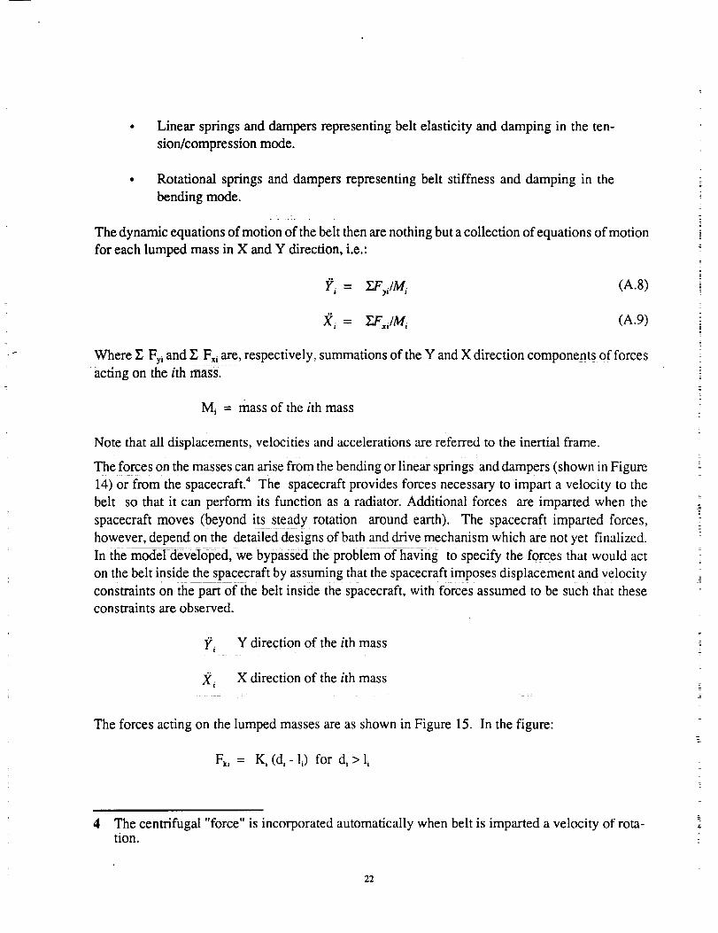
The forces acting on the lumped masses are as shown in Figure 15. In the figure:
Fki = Ki (di- li) for di > li
4 The centrifugal "force" is incorporated automatically when belt is imparted a velocity of rota-tion.
22
where
and
= 0 for _<li
li = initial length of link i,
ki - linear stiffness (elasticity) of link i,
Fki = linear stiffness force in link i,
-- stretched length of link i.
I
di = ((Xi ÷, _ Xi)2 +(y, ÷, _ yi)2)z
where X_, Yi = coordinates of mass i
Ki = E, A/1 i
where Et = belt modulus of elasticity in tension
A = area of cross section of belt
Similarly, the damping force in link i, FDi, is given by
FDi = V i B/I;
where B = damping coefficient of a one meter long belt in stretching
V_ = stretching velocity of link i
Vi = (V_i+l - V_i) cos 0i + (Vri.l - Vyi) sin 0i
where V_,, Vr, = X and Y direction velocities of mass i
B = 2r_ Aff_,_
where _ = damping ratio of first natural frequency in
stretching
= linear mass density of belt (kg/m).
Similarly, the forces acting on the lumped masses due to belt bending are given by:
Fl; = (K;;_, +B;,_t;)/d;_;
F2_ = (Kt,_; + B;,W_)/4
where
(A.10)
(A.11)
(A.12)
(A.13)
(A.14)
(A.15)
(A. 16)
(A .17)
23
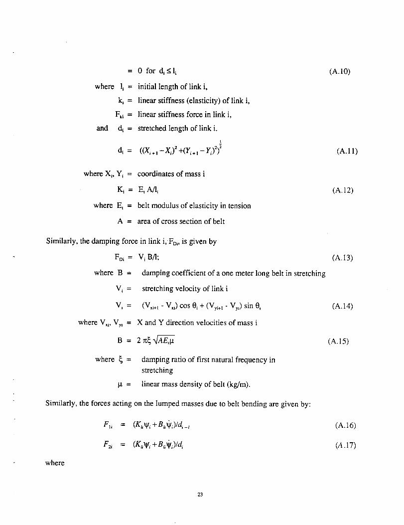
Ka = belt bending stiffness at mass i
Ba = belt bending damping coefficient at mass i
Xlti = O_-Oi_t = bendingangle (A.18)
_t_ = rate of bending angle change
Ku = EbI/li (A.19)
Bu = Bt/li (A.20)
where Eb = modulus of elasticity in bending
I = belt section modulus
B_ = damping coefficient for one meter long belt in bending
Also, for a belt made out of a mesh material,
B_ = 4 Brr/3r_ (A.21)
where rf = strand radius
The forces given by Equations (A.10), (A.13), (A.16) and (A.17) are decomposed into X and Y
components and added together so that mass accelerations in the X and Y directions can be obtained
using Equations (A.8) and (A.9).
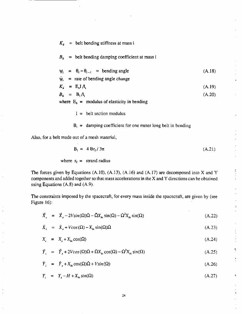
The constraints imposed by the spacecraft, for every mass inside the spacecraft, are given by (see
Figure 16):
X, = X, - 2Vsin(f_)_ - (2Xb, sin(Q) - _22X_, sin(Q) (A.22)
f(,, = f_, + Vcos(Q) --Xbi sin(Q)_ (A.23)
X_ = X,+Xb, cos(f_) (A.24)
Yi = Y, + 2Vcos(f2)O + D.Xb, cos(Q)- _2Xbi sin(O) (A.25)
I?_ = I_, +Xb, cos(Q)_+ Vsin(Q) (A.26)
Y, = Y, -n +Xb, sin(Q) (A.27)
24
where
X/, X,, g, = displacement, velocity and acceleration along inertial X axis
for mass i
Y_, I;"i, I?_ = the above along inertial Y axis
f2, _, _ = spacecraft angular displacement, velocity and acceleration
around inertial Z axis
X,, _'s, Xs = spacecraft displacement, velocity and acceleration along
inertial X axis
Y,, I;',, I?, = the above along inertial Y axis
Xbz = distance of lumped mass i from spacecraft center
H = height of belt center above liquid bath inside spacecraft
V = belt velocity.
This model was coded and converted into a computer simulation which generates snapshots of the
belt starting from an initial condition to any desired time subsequent to application of spacecraftmotion.
At this point it should be noted that the belt designs under consideration incorporate materials which
are quite inelastic. This causes a problem in performing computer simulations: the time required
for calculations is quite small, thus a significant amount of computer time is needed to perform
simulations. We tried to address this problem by developing a model which assumes the belt to be
made up of inelastic, rigid links connected with each other by hinges bending stiffness and damping.
This model, however, is quite complex and requires detailed information on forces acting on the
belt while inside the spacecraft. Such forces cannot be provided while the designs of bath and
drive mechanism are under development. Therefore, we had to abandon, at least temporarily, this
other model and continue using the model discussed above which, while slow and time consuming,
is appropriate for this stage of belt development.
A.4 COMPUTER PROGRAM SUMMARY
A computer program, titled Belt Radiator Simulation Program (BERS), was developed to simulate
the in-plane dynamic performance of the belt radiator. This program incorporated the lumped-
parameter model, described in the preceding subsection, and used a Runge-Kutta fourth order
integration algorithm to generate plots of belt shape for a variety of belt parameters and spacecraftmotions.
25
The input parameters for the program include:
• Number of lumped masses (N),
• Belt width (W),
• Belt drive length (2 max XBi),
• Belt length (unstretched) (Nli),
• Belt material density (mass per area) (g/W),
• Modulus of elasticity of belt material in tension (Et),
• Modulus of elasticity of belt material in bending (Eb),
• Belt area of cross section (A),
• Belt section modulus (I),
• Damping ratio for first stretching vibration mode (_),
• Radius of strand (for mesh type belt) (rf),
• Velocity of rotation (V), and
• Spacecraft motion parameters (acceleration magnitude, direction, duration)
The output of the program can include, if desired, a printout of displacements, velocities and
acceleration of any lumped mass, plus the forces acting on any mass. However, the preferred output
includes plots, similar to that shown in Figure 2, of belt shape at any time.
26
APPENDIX B
POINT DESIGN EQUATION DEVELOPMENT AND ANALYSIS METHODOLOGY
The development of the point design Equations is presented in this appendix. Although applied to
the particular mission defined in Reference 1, the formulations given here are sufficiently general
to be of use in any Moving Belt Radiator design.
B.1 RADIATIVE HEAT TRANSFER EQUATIONS
For this analysis, the initial assumptions which are made are: 1) the radiator is shaped like a
cylindrical hoop; 2) the radiator surfaces are edge on to the sun; and 3) no net exchange between
radiator elements that view each other are made. The radiative exchange between a radiative element
having a projected area dA s and its equivalent black-body surroundings is given by the relation:
['°_RST4 ]dQ_,=-26FRseR T_- dA s (B.1)-g-where:
eR is the total hemispherical emissivity of the radiator surfaces;
O_RS
FRs
is the absorptivity of the radiator surface to the radiation from its surroundings;
is the combined view factor of the radiator surface element 2dAR to its surroundings
(same for all elements);
is the temperature of the radiator element;
Ts is the equivalent black-body temperature of the surroundings;
is the Stefan-Boltzmann constant.
Making the further assumption that the spectral character and the radiant flux emitted by the
surroundings is that of a black-body having a temperature near that of the radiator and evoking
Kirchoff's Law, O_Rs/eR is approximately unity. Therefore Equation (B. 1) reduces to:
dQ,,,, _- 2 O FRseR [T_ - T,4] dAs (B.2)
The radiation actually coming from the surroundings may include that in the visible range (reflected
sunlight from the earth and spacecraft) as well as that in the infrared range (emitted from the earth
and spacecraft). A refined analysis would consider the spectral character of the radiation from the
surroundings incident on the radiator and its absorptivity to it. For example, assume that the sur-
roundings have an incident flux equal to that of a black-body at 250K but has 30 percent of the
energy due to reflected sunlight (Earth's albedo) and the remainder resulting from radiation from
nearby bodies at 300K. In this example a radiator using vacuum oil would have an absorptivity to
the long wavelength radiation near unity and an absorptivity/emissivity ratio in the visible band
near 0.1, resulting in an effective tXRs /eR = 0.73 and an effective black-body temperature of 23iK.
27
This lower effective temperature of the surroundings reduces the radiator area required to reject a
specified amount of heat by 8 percent from that calculated on the basis of Equation (B.1) with T s
= 250K. Similarly, a Liquid Belt Radiator using gallium operating in the sensible heat mode has
an estimated absorptivity/emissivity ratio in the visible band of 3, an effective O_Rs/eR = 1.6, and
an effective black-body temperature of 281K. In this case, Equation (B.2) underestimates the
required radiator area by 11 percent.
B.2 MBR GEOMETRICAL RELATIONSHIPS
To further simplify, Equation (B.2) was iinearized about the maximum operating temperature. This
linearization was assumed valid for the temperature ranges and variations considered in this analysis.
The quartic temperature difference (TR4 - Ts 4) may be expressed as:
_ - Ts = (T_ + T_) (TR - Ts) (Tk + Ts)
or in the final form:
TR _ T 4 _ T 3• s -'R(b) (T R-T s)
In this case:
a=1+ +tr .) tr .)where TR 3 is the linearized constant term fixed at the maximum belt radiating temperature occurring
at the exit of the bath heat exchanger. Thus, the net differential radiative exchange equation may
be rewritten in linear form as:
dQ,,,, = 20FRs eR b (TRMAX)3 (TR - Ts) dA, (B.3)
Where TR is the radiating temperature of the differential area dA s
Figure 17 portrays this differential area. This segment may be used to determine the energy transfer
for the entire MBR system. Using a differential form of the first law, we may write:
cpdTR =-QR" (w-dx) (B.4)
where:
W
dx
dTR
rh
QR"
is the width of the radiator belt (Figure 17);
is the differential length in the direction of belt travel;
is the temperature variation across the differential control volume;
is the mass flow of the belt material;
dQN_/dA s, or the net energy flux rate from the differential element.
Since the material flow rate can be written as:
m=pVtw
28
where:
9
V
t
w
is the density of the working fluid;
is the tangential belt speed;
is the belt thickness;
is the belt width.
Equation (B.3) can be reformulated to:
dTR 2FRsCeRb (TRMAX)3(TR--Ts)
dx - t 9 V cp (B.5)
The variation of the radiator temperature over the length of the belt expressed in the above equation
may now be easily solved by the separation of variables technique. (Assuming the properties e, Cp,
9, t and FRs do not vary with position x.) If the initial condition is given as:
T R(x = O) = TRMaX
The solution of the differential equation, expressing belt temperature as a function of position, maybe written as:
TR(x) - Ts = [TRMAX-- Ts] e -w (B.6)
where:
2 FRs _ et_b (TRMAX)3
_ll = 9 V cp t
however may be written in such a way as to greatly simplify Equation (B.5). Since an overall
first law balance on the radiator implies:
QR = P V c_ t ATea o
then
QR9Vcpt -
w (ATe,ao)
where:
ATRao
Q.
This allows _ to be re-expressed as:
2FRs 6eR b w (T_Max)3 (AT_o)
_¢= QR
or
is the temperature difference over the entire length of the belt.
is the total net radiative heat transfer.
29
v/=kw
This causes Equation (B.6) to become:
-kwxTR(x ) - Ts = [T_o,x - Ts] e
or over the entire length of the belt:
TR(I) - Ts = [TRMAX--TS] e -*w' (B.7)
Since, w.l = A,
where A_ is the single sided radiator area, Equation (B.6) may be used to generate this area directly.
Thus:
A =IIn(TRMax-T,1 (B.8)where:
k
2 FRs t_eR b (TRMAX) 3 (TRMAX-- TRMIN )
OR
and:
TRMIN = T R (I)
It must be noted that all of the above terms are either given or derived properties based on such
specific criteria as minimum evaporation mass loss, etc. This is true except for the view factor of
the radiator with respect to space, F_s, which must be selected. For the cylindrical hoop LBR design,
the selection of a view factor defined a particular geometrical relationship between the diameter
and width of the cylindrical structure. For example, a view factor of 0.9 resulted in a ratio of the
diameter to width of four. From the single sided area, A_ derived in Equation (B.8), the diameter,
width, and circumference of the cylindrical LBR may be determined. Specifically:
A, =l-w =n.D.w (B.9)
where now D and w (the diameter and width of the LBR) are interrelated by the view factor.
The mass of the LBR follows quite readily from this formulation, since:
M/.,R = t9 .A,. t (B.10)
The density of the LBR only includes that of the working fluid, with any screen mass effects ignored.
Analysis has shown this approximation to be reasonable in the case when an oil is usedin conjunction
with a plastic mesh structure. Different material combinations, metals and plastics for example,
must be carefully examined to determine their individual effects on the mass of cylindrical ribbon
structure. A similar equation can be used for a solid belt radiator, the only difference being that 9
is now the density of the belt material.
30
B.3 BELT SPEED DETERMINATION
The speed of the belt may be determined from the first law relation applied over the length of the
belt. In this case:
QR = P V cv _Sw
or
OR
V - (B.11)p t cp w (Tva_x - Tv_m)
For the point design (QR_ = 75 kwt), the belt speed was determined to be 0.8 m/s (2.5 fps).
B.4 INTERFACE HEAT EXCHANGER SIZING
An important component of the LBR system design was the interface heat exchanger. This heat
exchanger was to provide the means for the transfer of Brayton power cycle reject heat to the LBR
working fluid for eventual dissipation in space. It is predicted that both heat and mass transfer will
act as energy transfer modes in this system. For purposes of analysis, however, the former phe-
nomenon only was used as a basis for design thus resulting in more conservative exchanger size
estimates.
The heat exchanger design was based on compact heat exchanger theory (Reference 2). The device
was a counter flow model with the Brayton power cycle fluid being pumped through tubes in a
direction opposite to the direction of belt travel. Figure 18 schematically portrays this component.
From this figure it may be seen that there are two sides available for heat exchange.
Using the general form for convective heat transfer, we may write:
Q = UA AT (B.12)
where:
Q
AT
is the amount of heat to be transferred;
is a temperature difference which accounts for the temperature variation of each
stream as it moves through the exchanger;
is the overall heat transfer coefficient;
is the area available for heat transfer.
U
A
In order to account for the change of temperature of a stream as it moves through the exchanger,
the log mean temperature difference concept was used (Reference 3). This is defined as:
ATo-LMTD - (B. 13)
In (AT, / ATb)
For the point design conditions specified, Figure 19 depicts the temperature differences AT_ and
AT b occurring at the interface heat exchanger.
Evaluation with respect to these values gives:
31
LMTD = 52.7 K
The overall heat transfer coefficient U was assumed to be 567.6 W/M2"K (approximately 100
Btu/hr,ft2°°F). This value was believed readily attainable and in fact somewhat conservative for
the interface heat exchanger.
Employing these results and assumptions allows a heat exchanger area to be calculated. This area
however may be re-expressed as:
Anx = 2 w Lnx
where:
w is the width of the heat exchanger (assumed to be the same as the width of the belt
determined in Section B.2)
LHx is the length of the heat exchanger in the direction of belt travel.
The "2" in the above formulation accounts for the two sides available for energy transfer. Employing
these many results leads to the relationship:
Q (B.14)LHX = 2 U w (LMTD )
or more specifically:
a [kw]. 103
Lrtx(m) = 59825 w [m]
For the point design, this equation was used to calculate a heat exchanger length of 0.37 m (1.21
ft) corresponding to a total area of 2.51 m 2 (27.0 ft2).
B.5 PARASmC POWER LOSSES
The parasitic power refers to the rate of energy required to overcome the drag forces encountered
as the belt moves through the bath. This analysis assumes the existence of Couette flow with a
linear velocity distribution across the gap of the interface heat exchanger. The power required to
overcome viscous drag was written as:
_V 2,,P =--zwLnx
a
where:
kt is the viscosity of the working fluid;
V
w
L.xa
(B.15)
is the speed of the belt;
is the width of the belt;
is the length of the heat exchanger as calculated in Section B.4;
is the single sided gap distance from the top heat exchanger plate to the surface
of the belt structure.
32
To account for other drag forces including bath containment seals (i.e. wipers), beating drag, etc.,
the viscous drag defined in Equation (B.15) was doubled. Thus the total system power required to
overcome all sources of drag may be written as:
P =l'tV-----_24wLt_ (B.16)a
For the purposes of this analysis, the viscosity I.t was assumed to be a logarithmic function of
temperature (Figure 20). The value used in the calculations was determined from the arithmetic
mean temperature of the bath for particular inlet and outlet conditions.
For the point design, temperatures of 330K at the outlet and 300K at the inlet resulted in an average
viscosity for the working fluid of 1.75 Nos/m (0.0365 lbt°s/ft2). Employing this result along with
the other relations determined in this appendix, a gap width of 0.56cm (0.22 inch) resulted in a
total parasitic loss of less than 1 kw. The actual power required to overcome this 1 kw would be
at most 33% higher depending on the efficiency of the motor(s) used to drive the belt. It should be
noted that alternative interface heat exchanger designs are possible which not only provide the
required heat transfer but minimize drag losses.
B.6 ORBITAL AERODYNAMIC DRAG
An estimate of the aerodynamic drag force on the LBR can be gained by considering a model
consisting of a normal plane area travelling through a rarefied atmosphere at orbital velocity.
Attention is focused on aerodynamic conditions at an orbital altitude of 270 nautical miles, where
(Reference 4):
orbital velocity, Vo
mean molecular weight of atmosphere, M
average particle mass, m
mean free-path of particle
average particle velocity
particle concentration, n
= 7.9 km/s
= 18.3 (principally atomic and molecular
oxygen and nitrogen)
= 3.04 x 10.23 g
= 104 m
= 1.4 km/s
= 10S/cm 3
As the mean free path is much greater than any radiator dimension, the radiator operates in the
free-molecular flow regime. The drag force can be computed by considering the momentum
exchange of particles colliding with the radiator surface. As the orbital velocity is much larger
(approximately 8 times) than the particle velocity, the pressure at the radiator surface is determined
by the orbital speed. Assuming that the collisions of particles with the surface are elastic and
reflected diffusely, the pressure on the front face of the normal area is:
(V°) 4+--_-e =nmVo V o =-_nmV 2 (B.17)
33
and the pressure on the back surface is insignificant. Accordingly, an estimate of the drag force on
the LBR is given by:
4
F D = PAp = "_A,nmVo
where:
FD
Ap
(B.18)
is the aerodynamic drag force;
is the area projected normal to the orbital velocity other quantities as previously
defined.
Substituting the appropriate numerical values, we get
F° = 2.53 x lO-SN/m 2Ap
It may be of interest to note that the drag in free-molecular flow (calculated from Equation (B. 18))
is 2.67 times that appropriate to a bluff body (drag coefficient equal to unity) in a continuum flow
having the same density and approach velocity.
B.7 REFERENCES TO APPENDIX B
1) Preliminary Evaluation of a Liquid Belt Radiator for Space Applications, NASA Contractor
Report 174807, December, 1984.
2) Kays and London, Compact HeatExchanger_, Figure 2-i 2.
3) Rohsenow, W and H. Choi, Heat Mass and Momentum Transfer, 1961, page 310.
4) Santeler, D.J., Et AI, "Vacuum Technology and Space Simulation," NASA SP-105, 1966.
34
APPENDIX C
VIEW FACTOR RELATIONSHIP FOR CYLINDRICAL MBR
The MBR point design, a 75 kW radiator which is discussed in Reference 1, is based on the
assumption that the radiator is in a cylindrical configuration of radius R, and axial dimension (or
width), W. For purposes of this analysis, the outside surface of the radiator will be called surface
1 and the inside surface 2. It will be assumed that the portion of the MBR surface area that passes
through the bath can be neglected as small compared to the full MBR surface. Therefore, an analysis
for a full open cylinder will be assumed.
The key parameter required in the analysis is the total view factor of the entire radiator to space,
F_. It is composed of: (1) the view factor of the outer surface to space, F_s, which is always unity;
and (2) the view factor of the inner surface to space Fzs. The three view factors are related accordingto the relation:
A a FRS = 0.5 A s Fts + 0.5 A B F2s (C. 1)
where: AB = 2As = inner and outer belt surface area.
Equation (C. 1) reduces to:
FRs = 0.5 (1 + F2s ) (C.2)
F2s is calculated by referring to equations previously derived in Reference 2. The view factor F34 ,
of two cylindrical discs (3 and 4) of radius R spaced a distance W apart is given as follows and is
illustrated in Figure 21.
4(R'] 2
Equation (C.3) is related to the view factor of the inner surface of a cylinder, surface 2, to space (in
this case the ends of the cylinder) via the following relationships.
Since it may be proved that:
F23 = F_
the expression:
/'22 = 1-/'23-F24
may be rewritten as:
['22 = I - 2 ['23 (C.4)
Furthermore, since
A3F32 = A2F23
and:
35
F32= 1 -F34
or we may write:
A3
F23=_22 (1 -F34)
By substitutingEquation (C.5)into(C.4),the usefulexpression:
F22 = 1-2[_(1-F34) ]
can be derived. F_ is calculated from Equation (C.3).
Finally, the view factor to space of the inner surface of the cylindrical belt array is given by:
F2s = 1 - F22
Fzs = 2 (1 - F34
(C.5)
(C.6)
(C.7)
The calculation of the full MBR view factor to space is completely derived by substituting Equation
(C.7) into (C.2) to give:
A3
FRs = O.5 + -_2(1- F34) (C.8)
The results of a parametric evaluation of Equations (C.6), (C.7), and (C.8) are plotted in Figure 22.
Rfffrences to Ao0endix C
(1) _i]rninary Evaluation of a Liquid Belt Radiator for Space Applications, NASA Contractor
Report 174807, December, 1984.
(2) Jacob, M., Heat Transfer, Vol. II, John Wiley & Sons, New York, 1957.
36
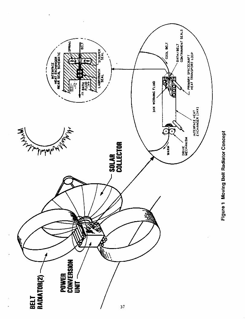
37
\
/
e_
0
0
!._
0
,m
n-
o3,m
>0
O3
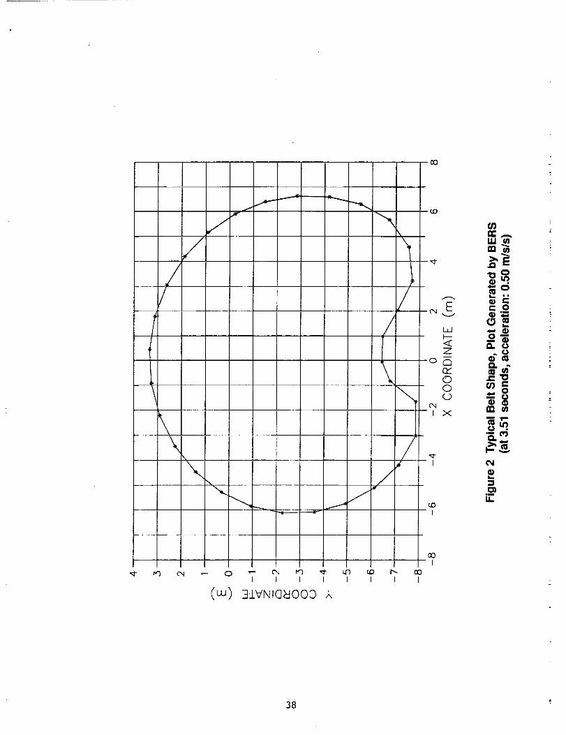
//
//
\\
'\\
f.I
f
..... L
/
\
\
/
\
/
c.o
_Ev
i.i
Zor'-_
rY00c_)
c_t X
I
c.oI
I.IJ
"_"0,,e"
_" 0
_o_11. o
m
ffl o
_ •"_. cO
IN
_ ¢N ,,-- ,,'- c'_ _ ._-0 I I I I
(w) 3J_VNla_o00 ,k
r..OI I I
COI
COI
38
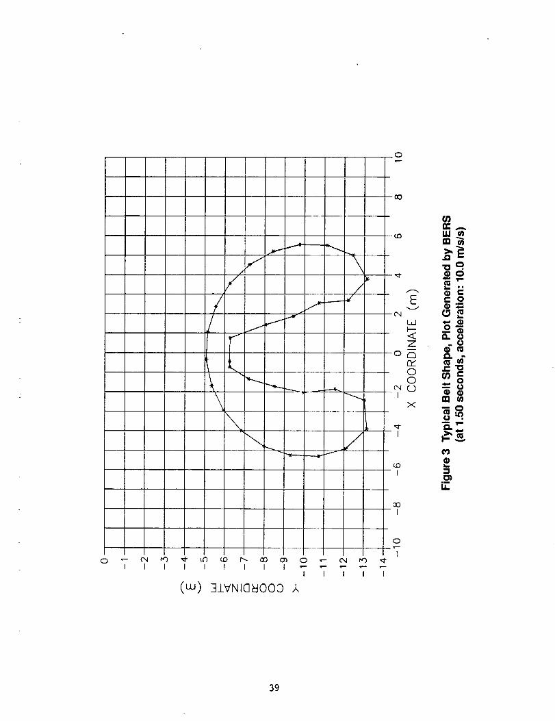
0
,i- \/
7._____,,,,A
\\
00
8
L._
<CZ
P_00
1
X
I
I
00I
_A
-0o
C 0
_U
m_
mmOm
i!
I1_
0 "- 0,,I I'_ _ LC) _0 I'_ O0 O_ 0 ','- C_ I_)I I I I I I I I .....
I I I I I
(cu) 3J.VNI@_IOOO ,k
o
I
39
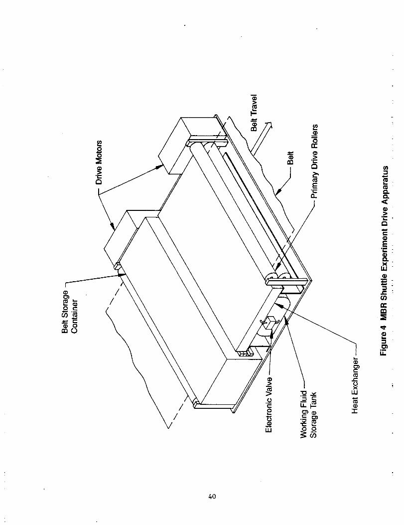
//
//
40
D.O.,<O)
CO)
l,IJObmmdmlm(ml
,,C
n-
_)I.i
0%mm
LL
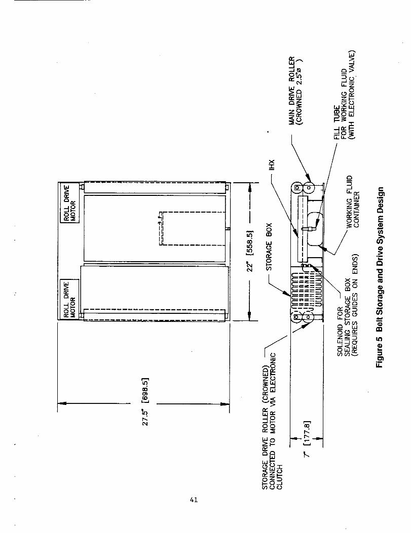
. oo o I-.........................IIIU_
m
0_
O0n-_E
i
0oo_
v
uF)
_4
OOt_
C4
X0
Z
Ib-ZO
O0r,.._
,,,!I---
.._1
Z o
L_
,m
E
ffl
im
e-
o
II1
,m
41
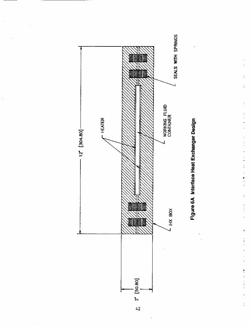
0GO
0
.I-
Ci
_C_D
_DL_
0_ii
LL
rml
oood
42
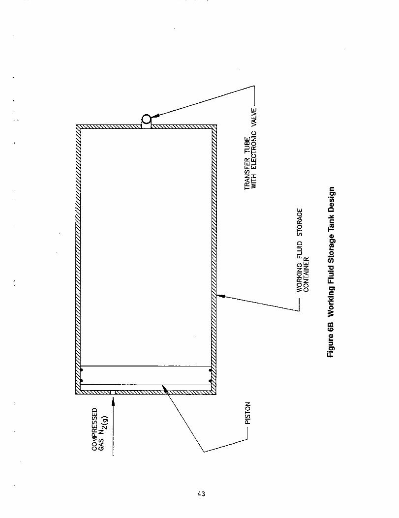
43
C
0
,m
m
LL
e"Jw
0
lu
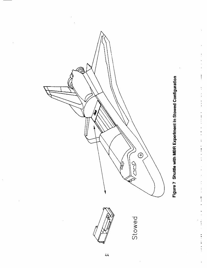
¥
44
g
0
!._=
iI_.
9_
u_
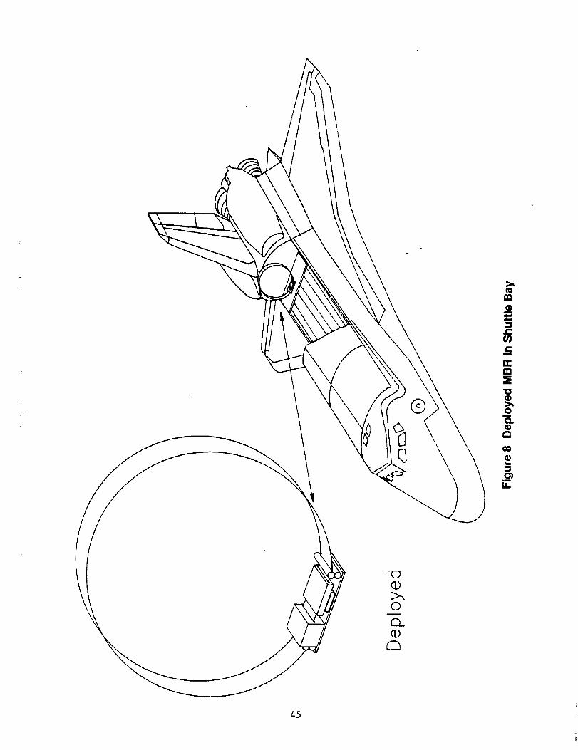
c_
i,omp
cm
n.m_E
Omm
co
Im
ill
IL
-U©
©
Q_CD
45
/
IRII
V
TI
\
Tx. T2 = Tension Forces
F - Centrifugal'Force
Y
_X
Z
Inertial Frame
T4
©©
Figure 9 Steady-State Condition of the Belt
46
A_ C_ntrifugalForceGravitationalForce
_m__ Belt
¢g
Earth Center
Figure 10 An Imbalance in Centrifugal and Gravitational Forces
47
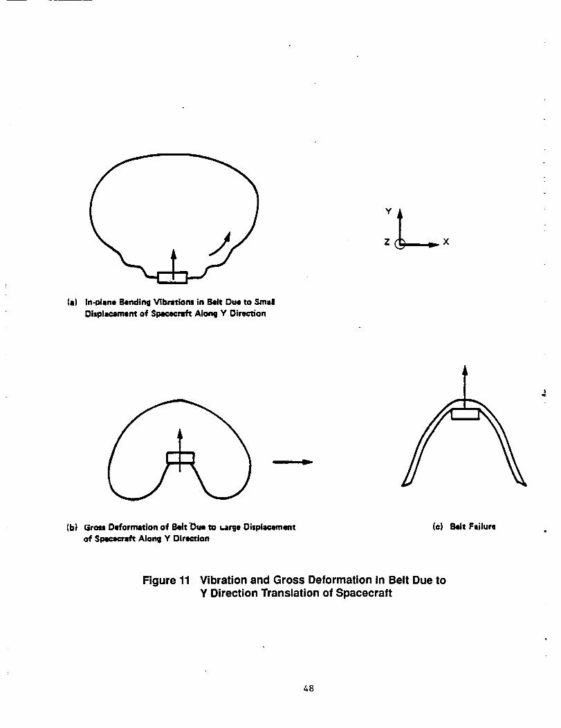
(a) In-Mane BendingVibratiom in Belt Due to StudDisplacement of SpacecraftAlong Y Oirection
|
(b) GrossDeformation of Bett-Oueto _arge Displacementof Spacecxz_Along Y Direction
(c) Belt Failure
Figure 11 Vibration and Gross Deformation in Belt Due toY Direction Translation of Spacecraft
48
tential Region for Belt Crease
;...-
Z
(a) TremJadon Along X Axis
/Potential Region for Belt Crease
(b) Rotation Around Z Axis
(For translation alon(j Y axis, see Figure 2.3 (b).)
Figure 12 Gross Deformation in Belt Due to In-Plane Motion of Spacecraft
49
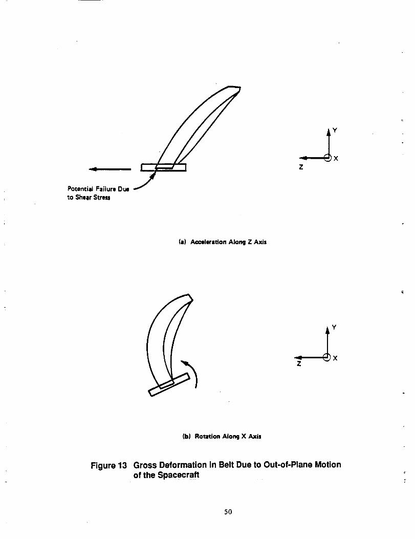
II
Potendal Failure Due
to Shear Stress
Z
(a) Acceleration Along Z Axis
A
Z
(b) Rotation Along X Axis
Figure 13 Gross Deformation in Belt Due to Out-of-Plane Motionof the Spacecraft
5O
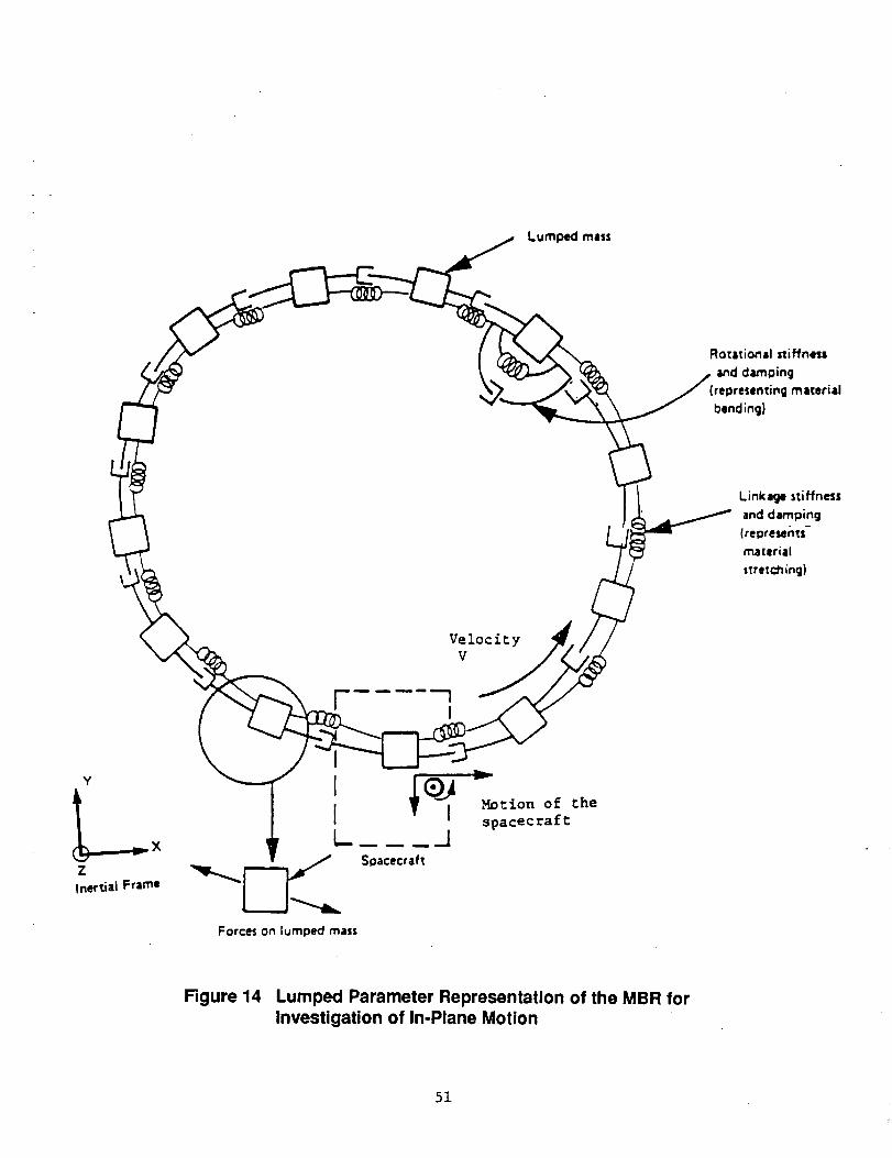
Ro_i:ionil stif'fness
and damoing
(rel_resenting material
bending)
Linkage stiffness
and damping
(re_resents-
materiil
stretch ;ng)
I
VelocityV
Y
ZInertial Frame
Forces on lumped mass
Figure 14 Lumped Parameter Representation of the MBR forInvestigation of In-Plane Motion
51
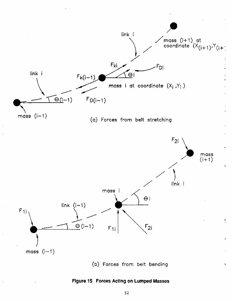
link i
mass (i- 1)
linki
_ ..__.....--FDi
Fk(i-_ i
mass i at coordinate (X i ,Yi )
/ mass (i+1) .at
coordinate (X(i +l),Y(i+.
FD(i-I)
(a) Forces from belt stretching
mass i
link (i-I)
(9 (i-I)
)mass (i-I)
/
F1i
//
F2i\
//
link i
mass(i+I)
(b) Forces from belt bending
Figure 15 Forces Acting on Lumped Masses
52
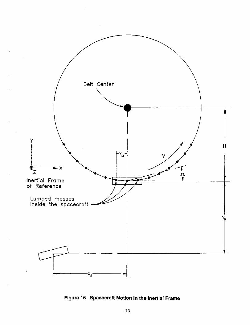
Y IZ
Inertial Frame _-_
of Reference ___l _Lumped massesinside the spacecraft
H
Ys
X_
Figure 16 Spacecraft Motion in the Inertial Frame
53
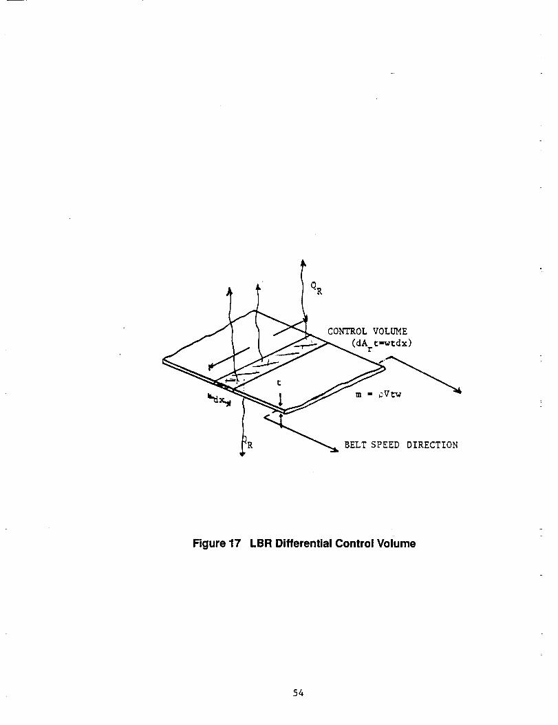
_ CONTROL VOLUME
wtdx)
--7 IR_ BELT SPEED DIRECTION
Figure 17 LBR Differential Control Volume
54
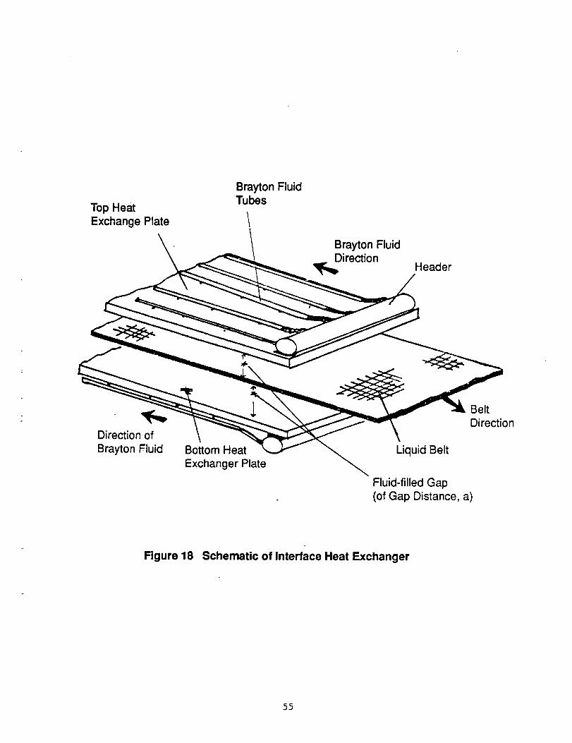
Top HeatExchange Plate
Brayton FluidTubes
Brayton Fluid
irection Header
Direction of
Brayton Fluid Bottom Heat
Exchanger Plate
Belt
Direction
Liquid Belt
Fluid-filled Gap
(of Gap Distance, a)
Figure 18 Schematic of Interface Heat Exchanger
55
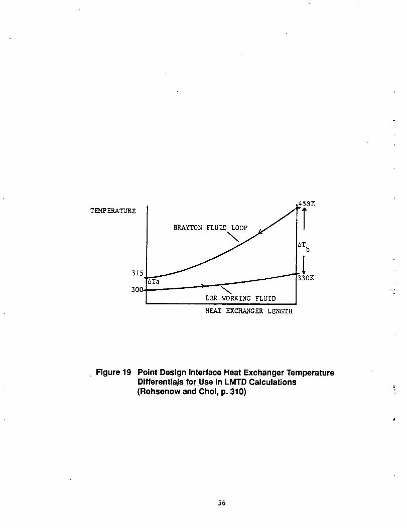
TEMPERATURE
315
300.
BRAYTON FLUID<0:/_" _418///_i
X
laTb
LBR WORKING FLUID
HEAT EXCHANGER LENGTH
Figure 19 Point Design Interface Heat Exchanger TemperatureDifferentials for Use in LMTD Calculations
(Rohsenow and Choi, p. 310)
56
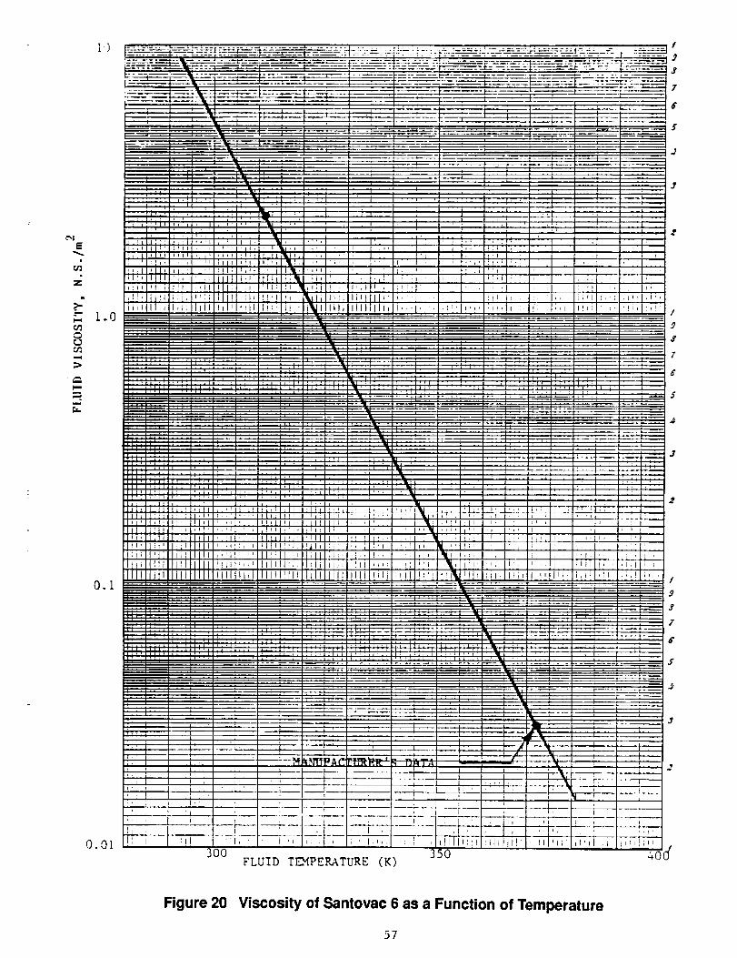
[ ()
+.,.;.¢
a
>-" l.O
:>
l.m
=+m
r.z,.
O.l
o.ot !_i
Figure 20 Viscosity of Santovac 6 as a Function of Temperature
57
C_
iiiC_
iirr
Z0
Iiiu.J_
LL_fro
C_Orn
iiia
zz
T,- C'_I
Will
LLllrrrr
c_
im
L.
0
L_
E0
q_
lIB
i!
IJL
5B
L__IJ_b_
IIi
_t_t
\
(D
\
\%
J
<_
<>
<>
Ir
Y
/
6 c$ o d o
_o_aoA M_!A
0
r_
0
ry
r'n
o
o
or_
C0
tm
"',1
,m
00
...Im
0,!
c,mD
0
i,......
00
o
0
,!
59
Report Documentation Page
1. RenoctNo. 2. GovernmentAccessionNo.
NASA CR-185168
4.Ti,erandSub_e
Conceptual Design of MBR Shuttle-Attached Experiment
Technical Requirements Document
7. A,_,,(,)
Jerry L. Aguilar
9. Performl_O_gsnlz_lonNemelindAddre_
Arthur D. Little, Inc.
20 Acorn Park
Cambridge, MA 02140
12. ,._onsod_ AgencyNameandAddm_
NASA Lewis Research Center
21000 Brookpark Road
Cleveland, OH 44135
3. R_'s CatalogNo.
5. Repo_Date
November 1989
6. Performi_ Orga.izatlo. Code
8. PedormlngOrgantzalio.ReportNo.
lO. WorkUnitNo.
506-48-4A
11. Contr_ o¢GrantNo.
NAS3-25356
13. Typeof ReportandPeriodCovered
Contractor Report Final
14. ,_soriflg AgencyCode
15. SupplementaryNotes
Project Manager, Alan White, Power Technology Division, NASA Lewis Research Center
In-Space Experiments Focal Point, Olga Gonzalez-Sanabrla
16. Abstract
The technical requirements for a shuttle-attached Moving Belt Radiator (MBR)
experiment are defined. The MBR is an advanced radiator concept in which a rotating
belt radiates thermal energy to space. The requirements for integrating the MBR
experiment in the shuttle bay are discussed. Requirements for the belt material and
working fluid are outlined along with some possible options. The proposed size and
relationship to a full scale Moving Belt Radiator are defined. The experiment is
defined with the primary goal of dynamic testing and a secondary goal of
demonstrating the sealing and heat transfer characteristics. A perturbation system
which will simulate a docking maneuver or other type of short term acceleration is
proposed for inclusion in the experimental apparatus. A deployment and retraction
capability which will aid in evaluating the dynamics of a belt during such a
maneuver is also described. The proposedtest sequence for the experiment is
presented. Details of the conceptual design are not presented herein, but rather
in a separate Final Report.
17. KeyWords(Suggesl__ Aut_s))
Moving Belt Radiator
Advanced Space Radiator
Space Power
Shuttle Experiment
lg. Securi_ Classif, (_ th_ re_d)
Unclassified
18. Dt_i_tion Statem_t
Unclasslfied-Unlimited
Subject Category 20
_. ,_cufi_ Clusif. (ofthis page)Unclassified
21. Noofpages 22. Pr_'e"
59 A04
._a FOAMte_ OCTM "For sate by the National Technical Information Service, Spnngfv.=td,Virginia 22161