gladiator - hawk measure · overview principle of operation the gladiator acoustic switch uses...
TRANSCRIPT

Sultan Sonar Manual Rev 1.0
A Higher Level of Performance
For more information, please visit >
GladiatorAcoustic Switch
Manual
Non-contact Self Cleaning Blocked Chute Detection

Table of Contents
2
Contents
Overview 3
Principle of Operation 3Typical Uses 3Function 3Features 3
System Components 4
Dimensions 5
Gladiator Remote Amplifier 5AWRT-JB Junction Box 5Remote Transducer 6Mounting Flange 6Remote Transducer with Spray Cleaner 6
Wiring 7
Gladiator Remote Amplifier 7AWRT-JB Junction Box 7Transducer Cable Extension 8
Mounting Dimensions & Instructions 9
Remote Transducer 9Remote Transducer with Spray Cleaner 9
System Overview 10
GAWC-SYS1 Acoustic Cleaner Components 10GAWC-SYS2 Acoustic Cleaner Components 11
Mounting Dimensions & Instructions 12
Application Examples 12
User Interface 13
Facia Controls 13
Power Up Sequence 14
Powering The System For The First Time 14
Commissioning 15
Blocked Chute Applications 15Level Switch Applications 16
Software 17
Displayed Diagnostics 17Main Menus 18Quickset Menu 18App Types 19App Types 20Advanced Menu 21
Relay 2 Functions 22
Relay 2 Functions 22Gain Based Maintenance / Spray Cleaner Setup Examples 23Time Based Spray Cleaner Setup Example 23
Transducer Initialization 24
Troubleshooting 25
Error Codes 25
Software Flow Chart 26
Part Numbering 30
Remote Amplifier 30Remote Transducer 30Junction Box 30Extra Cable 30Mounting Flange 30
Part Numbering / Specifications 31
Cleaning System (GAWC-SYS1) 31Cleaning System Mounting Flange 31Spray Cleaner Specifications 31Solenoid coil MD-2-24VDC-PC - #549903 31Cleaning System (GAWC-SYS2) 31
Specifications 32
Gladiator Acoustic Switch Series
Software v7.46 onwards
Overview
Principle of Operation
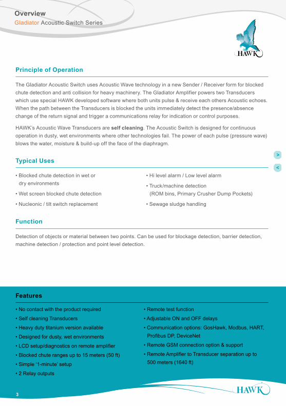
The Gladiator Acoustic Switch uses Acoustic Wave technology in a new Sender / Receiver form for blocked chute detection and anti collision for heavy machinery. The Gladiator Amplifier powers two Transducers which use special HAWK developed software where both units pulse & receive each others Acoustic echoes. When the path between the Transducers is blocked the units immediately detect the presence/absence change of the return signal and trigger a communications relay for indication or control purposes.
HAWK’s Acoustic Wave Transducers are self cleaning. The Acoustic Switch is designed for continuous operation in dusty, wet environments where other technologies fail. The power of each pulse (pressure wave) blows the water, moisture & build-up off the face of the diaphragm.
• No contact with the product required
• Self cleaning Transducers
• Heavy duty titanium version available
• Designed for dusty, wet environments
• LCD setup/diagnostics on remote amplifier
• Blocked chute ranges up to 15 meters (50 ft)
• Simple ‘1-minute’ setup
• 2 Relay outputs
• Remote test function
• Adjustable ON and OFF delays
• Communication options: GosHawk, Modbus, HART, Profibus DP, DeviceNet
• Remote GSM connection option & support
• Remote Amplifier to Transducer separation up to 500 meters (1640 ft)
Typical Uses
• Blocked chute detection in wet or dry environments
• Wet screen blocked chute detection
• Nucleonic / tilt switch replacement
• Hi level alarm / Low level alarm
• Truck/machine detection (ROM bins, Primary Crusher Dump Pockets)
• Sewage sludge handling
Features
3
Gladiator Acoustic Switch Series
Function
Detection of objects or material between two points. Can be used for blockage detection, barrier detection, machine detection / protection and point level detection.

System Components
4
Gladiator Acoustic Switch Series
CAL
RUN
Acoustic Switch 15kHz Remote Transducers with UHMW sleeve and Flange
Junction Box
RED
BLAC
KBL
UEW
HITE
RED
BLAC
KBL
UEW
HITE
RED
BLAC
KBL
UEW
HITE
or
Acoustic Switch 15kHz Remote Transducers with Spray Sleeve and Flange
RED
BLAC
KBL
UEW
HITE
RED
BLAC
KBL
UEW
HITE
RED
BLAC
KBL
UEW
HITE
RED
BLK
BLUE
WHI
T
RED
BLK
BLUE
WHI
T
RED
BLK
BLUE
WHI
T
AMP TX1 TX2
4x4mm
Open
170mm (6.7”)
3 x M20 x 1.5or 3/4” NPT adaptor
TopBottom
87m
m (3
.4”)
Closed (side)
Hawk AWRT-JB Junction Box Dimensions
150mm (5.9”)
60m
m (2
.4”)
80m
m (3
.1”)
System Components
Gladiator Remote Amplifier

Dimensions
5
Gladiator Acoustic Switch Series
Gladiator Remote Amplifier
14 mm (0.6”)
74 mm (2.9”)
78 mm (3.1”)
107
mm
(4.2
”)111.5 mm (4.4”)
4 mm (0.2”)
50 mm (2”)
131.
5 m
m (5
.2”)
7.5
mm
(0.3
”)
192.5 mm (7.6”)
141.
5 m
m (5
.6”)
190
mm
(7.5
”)
182.5 mm (7.2”)
147 mm (5.8”)
167.
5 m
m (6
.6”)
147 mm (5.8”)
30.7
mm
(1.2
”)158 mm (6.2”)
108
mm
(4.3
”)
190
mm
(7.5
”)
174 mm (6.9”)192.5 mm (7.6”)
182.5 mm (7.2”)
30.0 20.2
33.029.029.033.0
16.2
AWRT-JB Junction Box
RED
BLK
BLUE
WHI
T
RED
BLK
BLUE
WHI
T
RED
BLK
BLUE
WHI
T
AMP TX1 TX2
8mm
Open
170mm
80m
m
3 x M20 x 1.5or 3/4” NPT adaptor
Top
87m
m
Closed (side)
Hawk AWRT-JB Junction Box Dimensions
4mm
Bottom
150mm
60mm
RED
BLK
BLUE
WHI
T
RED
BLK
BLUE
WHI
T
RED
BLK
BLUE
WHI
T
AMP TX1 TX2
8mm
Open
170mm
80m
m
3 x M20 x 1.5or 3/4” NPT adaptor
Top
87m
m
Closed (side)
Hawk AWRT-JB Junction Box Dimensions
4mm
Bottom
150mm
60mm

6
DimensionsGladiator Acoustic Switch Series
Remote Transducer
With GAWSLV-3-X and FA4A-4 Flange
Mounting Flange
C
A B
STANDARD 4” ANSI FLANGE DIMENSIONS
FLANGE A (PCD) B (OD) TYPE mm in. mm in.
C (Hole)mm in.
FA4 190.5 7.5 228 9.0 19 0.75
SIZE
4”
No. Holes
8
100m
m (3
.9”)
102m
m (4
.0”)
123mm (4.8”)Flange
3 x O-rings
100m
m (3
.9”)
min. 95mm (3.7”)
max. 165mm (6.5”)
102m
m (4
.0”)
ID 100-102mm (3.9-4”)Pipe with 4” ANSI interface
Adjustable Flange Range
ID 100-102mm (3.9-4”)Pipe with 4” ANSI interface
350m
m13
.8”
350mm13.8”
100mm 100mm (3.9”)
4” ANSI FLANGE
UHMW Sleevewith O-ring
100.00mm
(3.9”)102.00m
m (4.0”)
min. 95mm (3.7”)
Locking RingPipewith4” ANSIinterface
min.
95mm
(3.7”)
max. 165m
m (6.5”)
35mm (1.4”)
Remote Transducer with Spray Cleaner
With FA4A-4-ASC Flange
ISOVIEW FOR REFERENCE ONLY
100mm (3.9”)
Spray Sleeve
102mm (4.0”)
123mm
(4.8”)240m
m (9.4”)
Flange
Sensor face threadedto end of steel thread(10mm cavity)
3 x O-rings
ISOVIEW FOR REFERENCE ONLY
100mm (3.9”)
Spray Sleeve
102mm (4.0”)
123mm
(4.8”)240m
m (9.4”)
Flange
Sensor face threadedto end of steel thread(10mm cavity)
3 x O-rings

Wiring
7
Gladiator Remote Amplifier
Gladiator Acoustic Switch Series
AWRT-JB Junction Box
Relay 1 - Output RelayRelay 2 - FailSafe Relay
TRANSDUCER 1 TRANSDUCER 2AMPLIFIER
Connect colour to colour
RED
BLAC
KBL
UEW
HITE
RED
BLAC
KBL
UEW
HITE
RED
BLAC
KBL
UEW
HITE
+ – A 1L+– NBRED
BLAC
K
BLUE
WHI
TEIs
SENSOR DC-In AC-In*4-20mA (N/A) COMMS
SLA
VE
IN
MA
STE
R O
UT
TEST
IN
RELAY 1N
C
CO
M
NO
RELAY 2
NC
CO
M
NO
1 2 3 4 5 6 7 8 9 10 11 12 13 14 15
16 17 18 19 20 21 22 23 24 25 26 27 28 29 30
Use long nose pliers toextract terminals
*AC-In is replaced by 36-60VDC with Power Input Option ‘C’.
Relay 1 - Output RelayRelay 2 - FailSafe/Cleaner Relay
+ – A 1L+– NBRED
BLAC
K
BLUE
WHI
TEIs
SENSOR DC-In AC-In*4-20mA* COMMS
SLA
VE
IN
MA
STE
R O
UT
TEST
IN
RELAY 1
NC
CO
M
NO
RELAY 2
NC
CO
M
NO
1 2 3 4 5 6 7 8 9 10 11 12 13 14 15
16 17 18 19 20 21 22 23 24 25 26 27 28 29 30
+24V
1N4004 Diode
1 2
SOLENDOID
*Model dependant
Solenoid wiring for Spray Cleaner
Relay 1 - Output RelayRelay 2 - FailSafe Relay
TRANSDUCER 1 TRANSDUCER 2AMPLIFIER
Connect colour to colour
RED
BLAC
KBL
UEW
HITE
RED
BLAC
KBL
UEW
HITE
RED
BLAC
KBL
UEW
HITE
+ – A 1L+– NBRED
BLAC
K
BLUE
WHI
TEIs
SENSOR DC-In AC-In*4-20mA (N/A) COMMS
SLA
VE
IN
MA
STE
R O
UT
TEST
IN
RELAY 1
NC
CO
M
NO
RELAY 2N
C
CO
M
NO
1 2 3 4 5 6 7 8 9 10 11 12 13 14 15
16 17 18 19 20 21 22 23 24 25 26 27 28 29 30

OptionalJunction
Box(for cable extension)
Cable Shield
Connect cable shield to ‘Black’Terminal atGladiatorRemoteAmplfier
Cable TypeBELDEN 3084ADEKORON IED183AA002or quality shielded instrumentation cable
RED
BLK
BLUE
WHI
T
RED
BLK
BLUE
WHI
T
RED
BLK
BLUE
WHI
T
AMP TX1 TX2
To Transducers 1 & 2Max. 30m cable lengthIf extending / replacing Transducer cable terminate cable shielding at TX BLK terminals
SHLD
RED
BLK
BLUE
WHI
TE
RED
BLAC
K
BLUE
WHI
TE
SENSOR
4 5 6 7
WiringGladiator Acoustic Switch Series
8
Transducer Cable Extension
Cable extension should only be the single cable run between AWRT-JB Junction Box 'Amplifier' terminal and the Remote Gladiator Amplifier.
Cable length between Transducer and AWRT-JB HAWK Junction must never exceed 30m.
AWRT-JB Junction Box
Gladiator Remote Amplifier

9
Mounting Dimensions & InstructionsGladiator Acoustic Switch Series
C
A B
STANDARD 4” ANSI FLANGE DIMENSIONS
FLANGE A (PCD) B (OD) TYPE mm in. mm in.
C (Hole)mm in.
FA4 190.5 7.5 228 9.0 19 0.75
SIZE
4”
No. Holes
8
100m
m (3
.9”)
102m
m (4
.0”)
123mm (4.8”)Flange
3 x O-rings
100m
m (3
.9”)
min. 95mm (3.7”)
max. 165mm (6.5”)
102m
m (4
.0”)
ID 100-102mm (3.9-4”)Pipe with 4” ANSI interface
Adjustable Flange Range
ID 100-102mm (3.9-4”)Pipe with 4” ANSI interface
General Mounting Instructions
• The mounting location must be away from the material flow path.
• Sleeve face should be flush with vessel wall interior
• O-rings form both a steal and act as acoustic de-coupling with the vessel. If required use a cavity filler (such as a silicone) to prevent material ingress around the sleeve.
• Material ingress between the sleeve and mounting can create acoustic coupling which can reduce sensor performance
• If there is potential for sensor face wear, the titanium version must be used
• If there is potential for high volume rock impact, consider a protective hood above (not in front of) sensor face location.
• Avoid mounting close to perpendicular walls where material build up can bridge to the Transducers.
• Avoid mounting close to perpendicular walls where material build up can bridge to the Transducers.
C
A B
STANDARD 4” ANSI FLANGE DIMENSIONS
FLANGE A (PCD) B (OD) TYPE mm in. mm in.
C (Hole)mm in.
FA4 190.5 7.5 228 9.0 19 0.75
SIZE
4”
No. Holes
8
100m
m (3
.9”)
102m
m (4
.0”)
123mm (4.8”)Flange
3 x O-rings
100m
m (3
.9”)
min. 95mm (3.7”)
max. 165mm (6.5”)
102m
m (4
.0”)
ID 100-102mm (3.9-4”)Pipe with 4” ANSI interface
Adjustable Flange Range
ID 100-102mm (3.9-4”)Pipe with 4” ANSI interface
Remote Transducer
With GAWSLV-3-X and FA4A-4 Flange
Remote Transducer with Spray Cleaner
With FA4A-4-ASC Flange
• Transducers should be aligned as accurately as possible for optimum performance.
• Never use the connection cable to carry or extract the Transducer
Spray Kit Mounting Instructions
• Solenoid and 4 way pipe converter should be mounted securely.
• Recommend 4 way pipe converter is kept close to mounting position on transducer - use 1” single pipe for as much distance as possible.
• Use a converter if required to interface with 1” HAWK recommended pipe connection.
ChuteWidth
AppStart Dist
AppEnd Dist
Live Measured Range
Distance BetweenTransducers
Min. 400mm (15.7")
Minimum Range

10
GAWC-SYS1 Acoustic Cleaner Components
A
C
B
D1
D2
1” BSP INT THD on SolenoidWater connection size determined by end user
Detail A
Solenoid Plug Socket
C1 C2
Detail C
Ø12mm Tube
Ø6mm Tube
Detail B
D1
D2
Part Description Part Number
C1 Hawk TransducerC2 Cleaner Sub-assembly GAWC-X
AWRT15_______AS*
SolenoidA
0.5” to 4 x 1/4” connecterB
GAWC-SL
GAWC-4P
D1 Ø 12mm tubeSupplied in single pieceTotal length = distance of part A to part B x 2(one length per transducer)
D2 Ø 6mm tubeSupplied in single pieceTotal length = distance of part B to part C x 8(Four equal lengths per transducer)
GAWC-12MMLz
GAWC-06MMLz
z = Specify length in metres*Consult Acoustic Switch datasheetfor full transducer part numbering
1
2
1N4004 DiodeWiring Diagram for Solenoid Plug Socket
Max. water pressure 14bar (1400kpa)Min. water pressure 1bar (100kpa)
Note: Full cleaner package GAWC-SYS1 includes all converters, reducers, connecters, 30m of 12mm tube, 20m of 6mm tube, solenoid and FA4A-4-ASC flanges. It does not include other eletronics (transducers, amplifier, junction box).
System OverviewGladiator Acoustic Switch Series
11
System OverviewGladiator Acoustic Switch Series
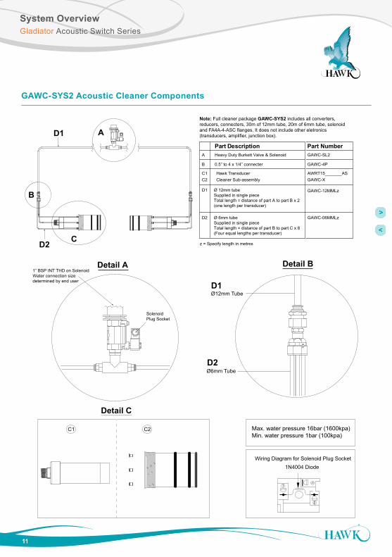
GAWC-SYS2 Acoustic Cleaner Components
A
C
B
D1
D2
1” BSP INT THD on SolenoidWater connection size determined by end user
Detail A
Solenoid Plug Socket
C1 C2
Detail C
Ø12mm Tube
Ø6mm Tube
Detail B
D1
D2
Part Description Part Number
C1 Hawk TransducerC2 Cleaner Sub-assembly GAWC-X
AWRT15_______AS
Heavy Duty Burkett Valve & SolenoidA
0.5” to 4 x 1/4” connecterB
GAWC-SL2
GAWC-4P
D1 Ø 12mm tubeSupplied in single pieceTotal length = distance of part A to part B x 2(one length per transducer)
D2 Ø 6mm tubeSupplied in single pieceTotal length = distance of part B to part C x 8(Four equal lengths per transducer)
GAWC-12MMLz
GAWC-06MMLz
z = Specify length in metres
1
2
1N4004 DiodeWiring Diagram for Solenoid Plug Socket
Max. water pressure 16bar (1600kpa)Min. water pressure 1bar (100kpa)
Note: Full cleaner package GAWC-SYS2 includes all converters, reducers, connecters, 30m of 12mm tube, 20m of 6mm tube, solenoid and FA4A-4-ASC flanges. It does not include other eletronics (transducers, amplifier, junction box).

12
Mounting Dimensions & InstructionsGladiator Acoustic Switch Series
Application Examples
CAL
RUN
CAL
RUN
RED
BLK
BLUE
WHI
T
RED
BLK
BLUE
WHI
T
RED
BLK
BLUE
WHI
T
AMP TX1 TX2
RED
BLK
BLUE
WHI
T
RED
BLK
BLUE
WHI
T
RED
BLK
BLUE
WHI
T
AMP TX1 TX2
CAL
RUN
RED
BLK
BLUE
WHI
T
RED
BLK
BLUE
WHI
T
RED
BLK
BLUE
WHI
T
AMP TX1 TX2

User InterfaceGladiator Acoustic Switch Series
13
Facia Controls
Gladiator Amplifier
CAL
RUN
RELAY 1 RELAY 2 STATUS A STATUS B
1
2
3
4
6 75
1234567
Calibrate button
Down button
Up button
Relay LEDs 1 and 2
Run button
Display (LCD with backlight)
Status LEDs A and BStatus A blinking indicates units are pulsing correctly. Status B is not used
In Run Mode(A) Press and hold - interrupts normal operations and allows access to software menu headings.
In Calibrate Mode(B) Steps into a menu selection to allow editing (down one level) (C) Saves selected value and moves onto the next menu item.
In Run Mode(A) Hides diagnostics if they are in view and returns to the standard running display.
In Calibrate Mode(B) Steps out of a menu or selection (up one level). Parameter value will be stored automatically when stepping up. (C) Returns to running mode from the top level menu.
In Run Mode(A) Scrolls through operating diagnostics on display LCD.
In Calibrate Mode(B) Scrolls through software parameters when browsing the menus. (C) Changes display value when editing a parameter.
All software adjustments can be made by the push buttons on the amplifier facia.

Power Up SequenceGladiator Acoustic Switch Series
14
Powering The System For The First Time
Upon power up the system scrolls through system information including software revisions, model types, serial numbers and device ID.
The first power up of an entirely new system will require Transducer Initialization. See 'Transducer Initialization ' section for details.
After this sequence is complete the unit will begin pulsing and display Sensor Value% on the display.
The system is now ready for Commissioning.

15
CommissioningGladiator Acoustic Switch Series
• Ensure system is mounted as suggested (see Mounting Dimensions & Instructions)
• Check where the actual level or target is relative to the sensors. Make sure that the material is not blocking the path between the Transducers.
Blocked Chute Applications
Parameter Instruction
1. Set App TypeThe system comes pre-set to Blocked Chute. To configure re-select the App Type. You will be prompted to 'Re-Configure', Select 'Yes'.
2. Set ModeAdvanced or Standard. Advanced is recommended for Blocked Chute applications.
3. Set ChuteWidthYou will be prompted to enter the width of the chute (this should also be the distance between each Transducer face). An accurate value is critical to system performance.
4. Set Back Chute Cutoff The default Back Chute Cutoff Distance is +350mm (13.7") of the ChuteWidth value. This parameter allows for additional refections to be accepted as a good reading by the system.
6. Set Switch Point%Set the Sensor Value% the unit must pass before triggering Relay 1. The Default value is acceptable for most applications. It can be increased to provide stability in difficult applications.
7. Set Relay Delay Timer Set the On and Off Delay timers for Relay 1.
8. RUN System Press RUN several times to commence unit operation.

CommissioningGladiator Acoustic Switch Series
16
• Ensure system is mounted as suggested (see Mounting Dimensions & Instructions)
• Check where the actual level or target is relative to the sensors. Make sure that the material is not blocking the path between the Transducers.
Level Switch Applications
Parameter Instruction
1. Set App Type Set App Type to 'Switch'.
2. Set ModeAdvanced or Standard. Advanced is recommended for Level Switch applications.
2. Set Application WidthSet Start Distance and End Distance. This span should encompass the distance to the opposing Transducer.
3. Set Sensitivity%For simple / clean applications, set the unit to a high Sensitivity% value. For difficult / dirty applications, set a low Sensitivity% value.
4. Set Switch Point%Set the Sensor Value% the unit must pass before triggering Relay 1. The Default value is acceptable for most applications. It can be increased to provide stability in difficult applications.
4.Set Relay Delay Timer Set the On and Off Delay timers for Relay 1.
5. RUN System Press RUN several times to commence unit operation.

17
SoftwareGladiator Acoustic Switch Series
Displayed Diagnostics
Use the buttons to cycle through Diagnostics on the top line of the Display.
Diagnostic DescriptionSensor Value Default Display. 2nd Line indicates actual % value.
Sensor Will display 1 or 2.for Transducer 1 or 2. Press UP and DOWN buttons at the same time to cycle between each Transducer.
E DistanceDisplays pulse by pulse echo distance. This may be space between sensors or Acoustic Modulated Tracking distance depending on application conditions.
Signa1Echo Signal Size in Volts. This value corresponds to the Sensor Value. 2V+ is good signal (Sensor Value of 0%). 1V is half signal (Sensor Value 50%) and 0V is no signal (Sensor Value 99-100%).
Recov1Recover Gain applied. Recover Gain is used to retain incoming Echoes. It is normal for this value to fluctuate rapidly.
Noise1Acoustic Noise detected. Enclosed spaces will have residual acoustics present. It is normal to have a constant and fluctuating Noise% value.
Gain1Total amount of Gain used by the system (includes Recover). It is normal for this value to fluctuate rapidly.
SignalAverage Echo Signal size between both Transducers (see Signal above for more information).
NormalFailedRecover
Unit operating normallyUnit in failsafe conditionsUnit searching for level / attempting to amplify signal.
Temperature Ambient temperature at Transducer.
Delay Relay 1 Delay timer. It is normal for this value to fluctuate rapidly.
Min Lowest recorded Sensor Value%.
Max Highest recorded Sensor Value%.
SW on Relay 1 Sensor Value switch on%.
SW off Relay 1 Sensor Value switch off%.
Diagnostics
__mA
Normal or Recover or Failed CAL
Level 2
Level 1
(Interface units only)
(Interface units only)
0.00%R: 55%
Quickset
Advanced
0.00%R: 55%
Quickset
Advanced
Unlock 0
CAL
The bottom line will always show the Sensor Value%
Diagnostic
Sensor Value %Note: Diagnostics with 1 at the end indicate Transducer 1, and 2 indicates Transducer 2.

18
SoftwareGladiator Acoustic Switch Series
All units are programmed by default with Unlock Code 0 (zero). This can be adjusted in the Advanced menu.
Main Menus
Quickset Menu
Diagnostics
__mA
Normal or Recover or Failed CAL
Level 2
Level 1
(Interface units only)
(Interface units only)
0.00%R: 55%
Quickset
Advanced
0.00%R: 55%
Quickset
Advanced
Unlock 0
CAL
Parameter Description Options
App TypeSee 'Programming App Types' on next page for detailed information.
• Blocked Chute• Switch
Switch PointSet Relay 1 trigger Sensor Value%. Default is 75%. When the Sensor Value exceeds this % the unit will commence the delay timer and then switches Relay 1.
• 1-99%
On Delay Relay 1 on delay timer. • Adjustable in seconds
Off Delay Relay 1 off delay timer. • Adjustable in seconds
Relay1 Action
Set default Relay 1 status. Failsafe High is Energized (EN) during normal operations and De-energized (DEN) when switches. Failsafe Low is De-energized (DEN) during normal conditions and Energized (EN) when switched.
• Failsafe High• Failsafe Low
Lock Code Adjust system Unlock code. Default is 0. 0-200
SoftwareGladiator Acoustic Switch Series
19
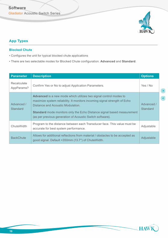
App Types
Parameter Description Options
Recalculate AppParams?
Confirm Yes or No to adjust Application Parameters. Yes / No
Advanced /Standard
Advanced is a new mode which utilizes two signal control modes to maximize system reliability. It monitors incoming signal strength of Echo Distance and Acoustic Modulation.
Standard mode monitors only the Echo Distance signal based measurement (as per previous generation of Acoustic Switch software).
Advanced / Standard
ChuteWidthProgram to the distance between each Transducer face. This value must be accurate for best system performance.
Adjustable
BackChuteAllows for additional reflections from material / obstacles to be accepted as good signal. Default +350mm (13.7") of ChuteWidth.
Adjustable
Blocked Chute
• Configures the unit for typical blocked chute applications
• There are two selectable modes for Blocked Chute configuration. Advanced and Standard.

SoftwareGladiator Acoustic Switch Series
20
Parameter Description OptionsRecalculate AppParams?
Confirm Yes or No to adjust Application Parameters. Yes / No
Advanced /Standard
Advanced is a new mode which utilizes two signal control modes to maximize system reliability. It monitors incoming signal strength of Echo Distance and Acoustic Modulation.
Standard mode monitors only the Echo Distance signal based measurement (as per previous generation of Acoustic Switch software).
Advanced / Standard
Start DistSet Start of Echo Filter Window distance.Typical setup for Start distance should be either equal to or slightly less than the distance between the Transducers.
Adjustable
End DistSet End of Echo Filter Window distance.Typical setup for End distance should be Start Distance +350mm (11.8").
Adjustable
Sensitivity
Set Sensitivity to media. A high value will make the unit more sensitive to switching and responding to lighter materials. A low value is suitable for most switch applications and will make the unit more resilient to false switching.
1-99%
Switch
• Configures the unit for typical level switch applications and Chute applications where Blocked Chute mode is too resilient (eg for light materials or narrow chutes) .
• There are two selectable modes for Blocked Chute configuration. Advanced and Standard.
App Types
Software
21
Gladiator Acoustic Switch Series
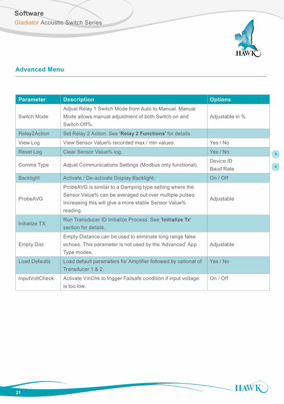
Advanced Menu
Parameter Description Options
Switch ModeAdjust Relay 1 Switch Mode from Auto to Manual. Manual Mode allows manual adjustment of both Switch on and Switch Off%.
Adjustable in %
Relay2Action Set Relay 2 Action. See 'Relay 2 Functions' for details.
View Log View Sensor Value% recorded max / min values. Yes / No
Reset Log Clear Sensor Value% log. Yes / No
Comms Type Adjust Communications Settings (Modbus only functional).Device IDBaud Rate
Backlight Activate / De-activate Display Backlight. On / Off
ProbeAVG
ProbeAVG is similar to a Damping type setting where the Sensor Value% can be averaged out over multiple pulses. Increasing this will give a more stable Sensor Value% reading.
Adjustable
Initialize TXRun Transducer ID Initialize Process. See 'Initialize Tx' section for details.
Empty DistEmpty Distance can be used to eliminate long range false echoes. This parameter is not used by the 'Advanced' App Type modes.
Adjustable
Load Defaults Load default parameters for Amplifier followed by optional of Transducer 1 & 2.
Yes / No
InputVoltCheck Activate VinChk to trigger Failsafe condition if input voltage is too low.
On / Off

Relay 2 FunctionsGladiator Acoustic Switch Series
22
Relay 2 has several functions available to support the system & installation.
Relay 2 Functions
Parameter Description
FailsafeRelay 2 is triggered in the event of a Failsafe condition. This includes insufficient input voltage, missing / faulted Transducers, Corrupt communications between Transducer / Amplifier and other general hardware faults.
Relay2 Mirrors Relay 1 functionality as level switch / alarm.
Maintenance Alarm
Relay 2 will be triggered when the Transducers Gain% value exceeds the programmed value CleanGainHigh%.
Relay 2 will de-activate when Transducer Gain% alls below the programmed CleanGainLow%.
Transducers using higher Gain% over time indicates that less signal is being received and is a symptom of build up within the chute.
GainOptClean
Gain based Cleaning function triggers Relay 2 to activate the Acoustic Spray Cleaner.
When the Transducer Gain% exceeds the programmed CleanGainHigh% value Relay 2 is triggered for the duration of 1/2 of the Relay 1 On Delay timer.
It will repeat the spray at the Clean Timer interval until the Transducer Gain% falls below the programmed CleanGainLow% value.
Transducers using higher Gain% over time indicates that less signal is being received and is a symptom of build up within the chute.
TimeOptCleanTime based Cleaning function triggers Relay 2 to activate the Acoustic Spray Cleaner. Relay 2 is triggered for the duration of 1/2 of the Relay 1 On Delay timer and will repeat at the selected interval for the selected duration.

23
Relay 2 FunctionsGladiator Acoustic Switch Series
Gain Based Maintenance / Spray Cleaner Setup Examples
The Gain based trigger averages the total used Gain of both transducers to activate and de-activate Relay 2. The system uses Gain to amplify the incoming signal.
The live Gain% value is accessible as a Diagnostic on the display. Press the UP or DOWN arrow until it is displayed on the top line:
When the system begins to use higher than normal Gain% this is an indication of potential problems within the application, most often material build up in the chute. High volumes of build up increase the risk of a blocked chute event.
Both modes use CleanGainHigh% to Activate Relay 2, and CleanGainLow% to de-activate Relay 2.
Setup Example - Maintenance Check Mode• Under Relay 2, select 'Maint'ce Chk', program CleanGainHigh% to 80% and then CleanGainLow% to 60%. The unit will switch Relay 2 when total Gain% is greater than 80%. The operator can examine the chute in this condition and take suitable action. The system will un-switch when Gain% returns below 60%.
Setup Example - Gain Option Cleaning Mode
• In ‘Quickset’ Set ‘On Delay’ to 4.0 seconds - this will provide a 2.0 second water blast.
• In ‘Advanced’ set ‘Relay2Action to ‘GainOptCln’ with a ‘CleanGainHi’ of 80%, ‘CleanGainLo’ of 70% and ‘Clean Timer’ to 5.0min.
• This will trigger the water spray for 2 seconds when Gain goes above 80%.
• The spray will repeat every 5 minutes until Gain goes below 70%.
• You can view Gain while the unit is running by using the arrow key to locate the diagnostic display.
Time Based Spray Cleaner Setup Example
The Time based trigger activates Relay 2 at every Clean Time interval for duration of 1/2 of the Relay 1 On Delay time.
Setup Example - Time Option Cleaning Mode• In ‘Quickset’ Set ‘On Delay’ to 4.0 seconds - this will provide a 2.0 second water blast.
• In ‘Advanced’ set ‘Relay2Action to ‘TimeOptCln’ with a ‘Clean Timer’ to 60min.
• The water spray will trigger every 60 minutes for a total of 2 seconds.

Transducer InitializationGladiator Acoustic Switch Series
24
Error 01 - Error 11• If the LCD is displaying ‘Error 01 or Error 11 after installing a single transducer or full system you may need to re-initialize a transducer.
• If your system is displaying Error 01 or Error 11 after the system has been working correctly it is possible there is a hardware problem.
• If Comm Err is displayed while navigating menus check your wiring, terminals, junction boxes and transducers for damage or connection problems.
Initializing a Transducer• If you need to re-initialize the transducer address you can run this program.
• You will have the option to clear each & initialize transducer address.
• First - Disconnect Transducer 2• Press and hold CAL to force the unit to open the ‘unlock’ menu.
• Navigate to the Initialize TX menu as per below:
After selecting ‘Yes’, you will see one of these messages:
T’ducer1 Initialize?• Transducer 1 is detected and has not been initialized.
• Press CAL to edit, press UP until you see ‘Yes’.
• Press CAL to select.
• Re-connect Transducer 2 and press RUN several times to re-activate the unit.
T’ducer 1 Ready• Press CAL to edit, press UP twice to display ‘Clear? Yes’.
• Press CAL.
• The unit will cycle to T’ducer 2 displaying ‘Ready’.
• Re-connect Transducer 2 and press RUN several times to re-activate the unit.
Plz connect Transducer 1• Press RUN firmly until it moves to 2nd Transducer.
• Display should read ‘T’ducer 2 Ready’ (if this does not occur, skip to below note).
• Press CAL to edit, press UP twice to display ‘Clear? Yes’. Press CAL.
• The unit will not have returned to the advanced menu.
• Press UP and re-enter TX initialize.
• You should now be prompted with T’ducer1 Initialize, refer to relevant steps.
*Note*: • If the unit menu does not scroll to ‘T’ducer 2 Ready’ you will need to perform a ‘Load Defaults’ routine (located in Advanced Menu). This will prompt you to load defaults and confirm selection followed by resetting the sensor - do not reset the sensors.
• After the load default press RUN to re-start the unit. Next, perform a power cycle of the entire system.
• When prompted to connect Wire Tx 1, Press CAL. When prompted to connect Transducer 1, press RUN.
• ‘T’ducer 2 Ready’ should now be displayed. Press UP arrow to display ‘Clear’. Press CAL. The unit will now re-start.
• Follow on-screen instructions to complete setup.
Initilize TX
Unlock 0CAL
x3
AdvancedCAL
CAL *edit* Yes CAL
Plz connect Transducer 1
T’ducer 1READY
T’ducer1Initiliz? No
T’ducer1 Initialize?
Plz connect Transducer 1
T’ducer 1 Ready
During the boot sequence of the amplifier information about each transducer is cycled on the LCD. Each transducer will pulse once during this phase confirming power is present.
If both transducers pulse at the same time they have been assigned the same TX ID. You will need to re-initialize one of them.

TroubleshootingGladiator Acoustic Switch Series
25
Error Codes
Too Many Transducers
• This code can be displayed if both transducers are already correctly initialized when run the Initialize TX program. Press and hold the RUN button to exit this code loop.
Com Retry
• Unit is attempting to communicate with a transducer.
Failed
• Unit has failed to communicate with both transducers.
• Check amplifier & junction box wiring connections.
• Pull each wire to ensure they are locked in correctly.
Error No 01:
• Amplifier cannot communicate with transducer 1.
Error No 11:
• Amplifier cannot communicate with transducer 2.
Existing installation• For both error codes 1 and 11 the first thing to check is the amplifier & junction box wiring connections, both HAWK and customer supplied if applicable.
• Pull each wire to ensure they are locked in correctly. • Check sensor for damage.
New installations• You may need to re-initialize the transducers.
• The re-initialization sequence assigns each an ID which the amplifier is looking to communicate with.
• The re-initialize program is in the ‘Advanced’ Menu.
• While an error code is on the screen you will need to push and firmly hold the CAL button to access the unlock screen. This may take 5-10 seconds.
Error 02:
• Amplifier can talk to transducer but transducer gives incorrect response.
• This can indicate a communication data corruption between Amplifier and Transducer.
• It can be a result of noise in data lines or one of data lines (blue or white) being open circuit.
Error 03:
• A communications option in output adjustment has been selected (eg Profibus, FF) but the module is not present, connected or responding.
Error 04:
• Amplifier is programmed with incorrect software.
Error 08:
• Incorrect transducer - ensure connected transducer is Acoustic Switch (AS).
Power Supply
• LCD / LEDs / Relays dimming or dropping out in non-blocked conditions.
• The GSASUS when powered by AC will output a DC voltage from the DC +/- terminals.
• You should read approx 16V stable from DC +/- while under AC power. If your AC power is stable and the DC is outputting a lower or unstable value there is likely a problem with the internal AC power supply.
• You can use a 24DC regulator and power the unit via DC terminals.
• High / Inconsistence switch % after calibration.
• See ‘setting maximum range’.

Software Flow ChartGladiator Acoustic Switch Series
26
Advanced
Switch Mode
Diagnostics
BlockedChute
Sensor Value
Sensor 1
E1Distance
Signa1
Recov1
Noise1
Recov2
Signal
Normal
Temp
Delay
Min
Max
SW Off
SW On
QuickSet
Relay1 Action
App Type
Switch Point
On Delay Adj
Off Delay Adj
CAL
CAL Blocked Chute
Switch
CAL
CAL
CAL
Sensitivity
Recalculate App type? No
Yes
Failsafe High
Failsafe Low
Advanced
CAL
CAL Auto
Manual
Relay2Action CAL Failsafe
Relay2
YesView Log CAL
YesReset Log CAL
Profibus
Comms Type CAL
DeviceNet
Modbus
HART
Baud Rate
Device ID
ProbeAVG
Initilize TX NoCAL
Yes
Empty Dist
LoadDefaults NoCAL
Yes
(Blocked Chute) (Switch)
App Start
App End
Chute Width
BackChute
CAL CAL
CAL
Lock Code
Not
Fun
ctio
nal
CAL
Back Light CAL On
Off
Maintnce Chk
GainOptClng
TimeOptClng
CleanGainHi
CleanGainLo
Clean Timer
CAL
Clean TimerCAL
No
CAL
Yes
Confirm Sel?
CAL
CAL ResetSensor1 ResetSensor2CAL
QuickSet

Software Flow ChartGladiator Acoustic Switch Series
27
Advanced
Switch Mode
Diagnostics
BlockedChute
Sensor Value
Sensor 1
E1Distance
Signa1
Recov1
Noise1
Recov2
Signal
Normal
Temp
Delay
Min
Max
SW Off
SW On
QuickSet
Relay1 Action
App Type
Switch Point
On Delay Adj
Off Delay Adj
CAL
CAL Blocked Chute
Switch
CAL
CAL
CAL
Sensitivity
Recalculate App type? No
Yes
Failsafe High
Failsafe Low
Advanced
CAL
CAL Auto
Manual
Relay2Action CAL Failsafe
Relay2
YesView Log CAL
YesReset Log CAL
Profibus
Comms Type CAL
DeviceNet
Modbus
HART
Baud Rate
Device ID
ProbeAVG
Initilize TX NoCAL
Yes
Empty Dist
LoadDefaults NoCAL
Yes
(Blocked Chute) (Switch)
App Start
App End
Chute Width
BackChute
CAL CAL
CAL
Lock Code
Not
Fun
ctio
nal
CAL
Back Light CAL On
Off
Maintnce Chk
GainOptClng
TimeOptClng
CleanGainHi
CleanGainLo
Clean Timer
CAL
Clean TimerCAL
No
CAL
Yes
Confirm Sel?
CAL
CAL ResetSensor1 ResetSensor2CAL
QuickSet

Software Flow ChartGladiator Acoustic Switch Series
28
Advanced
Switch Mode
Diagnostics
BlockedChute
Sensor Value
Sensor 1
E1Distance
Signa1
Recov1
Noise1
Recov2
Signal
Normal
Temp
Delay
Min
Max
SW Off
SW On
QuickSet
Relay1 Action
App Type
Switch Point
On Delay Adj
Off Delay Adj
CAL
CAL Blocked Chute
Switch
CAL
CAL
CAL
Sensitivity
Recalculate App type? No
Yes
Failsafe High
Failsafe Low
Advanced
CAL
CAL Auto
Manual
Relay2Action CAL Failsafe
Relay2
YesView Log CAL
YesReset Log CAL
Profibus
Comms Type CAL
DeviceNet
Modbus
HART
Baud Rate
Device ID
ProbeAVG
Initilize TX NoCAL
Yes
Empty Dist
LoadDefaults NoCAL
Yes
(Blocked Chute) (Switch)
App Start
App End
Chute Width
BackChute
CAL CAL
CAL
Lock Code
Not
Fun
ctio
nal
CAL
Back Light CAL On
Off
Maintnce Chk
GainOptClng
TimeOptClng
CleanGainHi
CleanGainLo
Clean Timer
CAL
Clean TimerCAL
No
CAL
Yes
Confirm Sel?
CAL
CAL ResetSensor1 ResetSensor2CAL
QuickSet

Software Flow ChartGladiator Acoustic Switch Series
29
Advanced
Switch Mode
Diagnostics
BlockedChute
Sensor Value
Sensor 1
E1Distance
Signa1
Recov1
Noise1
Recov2
Signal
Normal
Temp
Delay
Min
Max
SW Off
SW On
QuickSet
Relay1 Action
App Type
Switch Point
On Delay Adj
Off Delay Adj
CAL
CAL Blocked Chute
Switch
CAL
CAL
CAL
Sensitivity
Recalculate App type? No
Yes
Failsafe High
Failsafe Low
Advanced
CAL
CAL Auto
Manual
Relay2Action CAL Failsafe
Relay2
YesView Log CAL
YesReset Log CAL
Profibus
Comms Type CAL
DeviceNet
Modbus
HART
Baud Rate
Device ID
ProbeAVG
Initilize TX NoCAL
Yes
Empty Dist
LoadDefaults NoCAL
Yes
(Blocked Chute) (Switch)
App Start
App End
Chute Width
BackChute
CAL CAL
CAL
Lock Code
Not
Fun
ctio
nal
CAL
Back Light CAL On
Off
Maintnce Chk
GainOptClng
TimeOptClng
CleanGainHi
CleanGainLo
Clean Timer
CAL
Clean TimerCAL
No
CAL
Yes
Confirm Sel?
CAL
CAL ResetSensor1 ResetSensor2CAL
QuickSet

Part NumberingGladiator Acoustic Switch Series
30
AWRT-JB-01 HAWK multi purpose junction box for dual transducer applications
AWRT-JB-06 HAWK multi purpose junction box for dual transducer applications with 6m cable
Junction BoxRemote Amplifier
GSA Remote Gladiator System Amplifier Housing S Standard polycarbonate electronics housing
Power Supply B 12-30VDC C 36-60VDC U 12-30VDC and 90-260VAC
Output Options S Switch. 1 level relay, 1 failsafe relay, with Modbus
Other Options A22 ATEX Grp II Cat 3 GD T85°C IP67 Tamb -40°C to 70°C
GSA S U S
Extra Cable
CA-TXCC-R-C15 15m (49ft 2.5")CA-TXCC-R-C30 30m (94ft 5.1")CA-TXCC-R-C50 50m (164ft 0.5")CA-TXCC-R-C100 100m (328ft 1")
FA4A-4 HAWK 4” ANSI flange with decoupled connection flange for acoustic switch sleeve
FA4A-4-ASC HAWK 4” ANSI flange with decoupled connection flange for spray cleaner sleeve
Mounting Flange
Hazardous area approvals and intrinsically safe options available, contact your local distributor or head sales office for further information.
AWRT Acoustic Wave Remote Transducer 15 15kHz for applications with heavy duty self cleaning requirements Transducer Diaphragm / Sleeve Material T Teflon / UHMW (applications suitable for Teflon (no sensor face wear)) Y Titanium face / UHMW (applications with possible sensor face wear eg crushers) Transducer Housing Material 4 Polypropylene Thread Standards for End cap X Not Available Mounting Thread X 15kHz - GAWSLV-3-X sleeve mounted (3.5” BSP thread to suit FA4A-4 flange) Approval Standard X Not Required A22 ATEX Grp II Cat 3 GD T85°C IP67 Tamb -40°C to 70°C Connection C IP68 Sealed unit with cable Cable Length 15 15m cable (standard) 30 30m cable Accessories X UHMW sleeve Software Options AS Gladiator Acoustic Switch
AWRT 15 Y 4 X X X C 15 X AS
Remote Transducer

Part Numbering / SpecificationsGladiator Acoustic Switch Series
31
Water Pressure• Maximum: 14bar (1400kpa) • Minimum: 1bar (100kpa).
Water Quality• System requires good water quality. Install filter if required.
Solenoid coil MD-2-24VDC-PC - #549903
Feature Values
Assembly position Any
Switching position indicator No
Duty cycle 100%
Characteristic coil data 24V DC: 6,8W
Permissible voltage fluctuation +/- 10%
Protection class IP65
Ambient temperature -20...50oC
Max. tightening torque for fitting 0.5 Nm
Product weight 110 g
Electrical connection Per DIN EN 175301-803
Mounting type With knurled nut
Material information, solenoid coil Duroplast, Copper, Steel
Material information, coil Copper
GAWC-SYS1 cleaner package consists of GAWC-X GAWC-SL GAWC-4P GAWC-12MMLZ
GAWC-06MMLZ
Cleaning System (GAWC-SYS1) Cleaning System (GAWC-SYS2)
GAWC-SYS2 cleaner package consists of GAWC-X GAWC-SL2 GAWC-4P GAWC-12MMLZ GAWC-06MMLZ
Z = specify pipe length in metres
FA4A-4-ASC
Cleaning System Mounting Flange
Water Usage• Approximately 200ml per second per transducer (water pressure dependent).
Spray Cleaner Specifications

SpecificationsGladiator Acoustic Switch Series
Operating Voltage
• 12-30VDC (residual ripple no greater than 100mV) • 90-260VAC • 36-60VDC.
Power Consumption
• <0.8W @ 24VDC • <6W @ 48VDC • <5VA @ 240VAC • <3VA @ 115VAC.
Communications
• GosHawk, Modbus • Multidrop mode can address 1-250 units over 4 wires.
Relay Outputs: (2) Remote
• Form ‘C’ (SPDT) contacts, rated 5A at 240VAC resistive • Remote fail-safe test facility for one relay.
Operating Temperature
• Remote Electronics -40°C (-40°F) to 80°C (176°F) • Remote Transducers -20°C (-4°F) to 80°C (176°F).
Fail-Safe
• Selectable - presence or absence of material.
Maximum Range
• Blocked Chutes: Maximum: 15m (50ft) Minimum: 400mm (32”).
Junction Box to Amplifier Separation
• Up to 500m (1640ft) using specified extension cable (Belden 3084A).
Junction Box to Transducer Separation
• Up to 30m (98.5ft) using specified extension cable (Belden 3084A).
Maximum Operating Pressure
• 2 BAR.
Display
• 2 line x 12 character alphanumeric LCD • Backlight standard.
Memory - Remote
• Non-Volatile (No backup battery required) • >10 years data retention.
Enclosure Sealing
• Remote Electronics IP67 (NEMA 4x) • Remote Sensors IP68 • Junction Box IP67.
Cable Entries
• 4 x 20mm (0.8”), 1 x 16mm (0.6”) knock outs. • 1 x M20 Gland / 3/4” NPT threaded adapter.
Mounting
15kHz Blocked Chute • Transducer 4” ANSI flange with decoupled thread piece • Pipe Specification: 4-00” Z40 ID = 100mm Black Pipe • Remote Amplifier Back mount, DIN rail mount.
Typical Weight kg lb
• 15kHz Transducer 8 17.6 • Remote Amplifier 1 2.2
All
com
pany
or p
rodu
ct n
ames
are
regi
ster
ed tr
adem
arks
or
trade
mar
ks o
f the
ir re
spec
tive
owne
rs.
DO
C-A
CO
US
TIC
+AS
C-M
AN
v2.
0
0817
Hawk Measurement Systems(Head Office)15 - 17 Maurice Court Nunawading VIC 3131, AUSTRALIA
Phone: +61 3 9873 4750Fax: +61 3 9873 [email protected]
Hawk Measurement 90 Glenn Street Suite 100B, Lawrence, MA 01843, USA
Phone: +1 888 HAWKLEVEL (1-888-429-5538)Phone: +1 978 304 3000Fax: +1 978 304 [email protected]
For more information and global representatives: www.hawkmeasure.com