geri nursing manikin instructions.pdf · nasal lavage, gavage, and suctioning procedures cannot be...
TRANSCRIPT

GERi™/KERi™ the nURsing sKiLL mAniKins
the ideal manikin for all oBRA required training!
GERi™– LF04040U, LF04001U, LF04030U, LF04003UKERi™– LF04021U, LF04020U, LF04022U, LF04023U
instRUCtion mAnUAL
products by nascoCOPYRIGHT © NASCO 2007 PRINTED IN U.S.A. NP 081-07
other Available simulatorsLF00698U Adult Injectable Arm (White) LF00856U Female CatheterizationLF00885U Male Catheterization LF00901U Prostate Examination LF00906U Ostomy Care LF00929U Surgical Bandaging LF00957U Enema Administration LF00958U Pediatric Injectable Arm LF00961U Intramuscular Injection LF00984U Breast Examination LF00995U Arterial Puncture Arm LF00997U Adult Injectable Arm (Black) LF00999U Pediatric Injectable Head LF01008U Intradermal Injection Arm LF01012U Heart Catheterization (TPN) LF01019U Ear Examination LF01027U Peritoneal Dialysis LF01028U Suture Practice Arm LF01034U Suture Practice LegLF01036U Spinal Injection LF01037U Hemodialysis Arm LF01038U Episiotomy SuturingLF01042U Suture KitLF01062U Pelvic, Normal & Abnormal LF01063U Stump Bandaging, Upper LF01064U Stump Bandaging, Lower LF01069U Cervical Effacement LF01070U Birthing Station LF01082U Cricothyrotomy LF01083U Tracheostomy Care LF01084U Sigmoidoscopic
Examination LF01087U Central Venous Cannulation LF01095U Blood Pressure Arm LF01108U Infant Intraosseous Infusion
Simulator LF01121U Advanced IV Arm LF01131U Venipuncture and Injection ArmLF01139U Advanced IV Hand LF01142U Auscultation TrainerLF01143U Testicular ExamLF01152U Male & Female CatheterLF01155U CPR Dog
LF01162U Venatech IV Trainer LF01174U NG Tube & Track SkillsLF01184U Venatech IM & Sub Q LF01193U Special Needs BabyLF03000U CPARLENE® Series LF03601U Adult Airway Management Trainer with Stand LF03602U Adult Airway Management on Manikin LF03609U Child Airway Management Trainer with StandLF03616U Child CRiSis™ ManikinLF03617U Deluxe Child CRiSis™ Manikin with Arrhythmia TutorLF03620U PALS Update KitLF03623U Infant Airway Management Trainer with standLF03632U Child Intraosseous Infusion/ Femoral Access Leg on a StandLF03633U Child Airway Management Trainer with TorsoLF03693U Basic Buddy CPR ManikinLF03699U “Airway Larry” Airway Management TrainerLF03709U Infant CRiSis™ManikinLF03720U Baby Buddy Infant CPR ManikinLF03750U Fat Old FredLF03760U Airway Management/Cricoid Pressure TrainerLF03770U Chest TubeLF03953U CRiSis™ Manikin, completeLF03955U Deluxe CRiSis™ ManikinLF03965U Deluxe “Plus” CRiSis™ ManikinLF04200U Adult Sternal Intraosseous InfusionLF06001U CPR Prompt™ Adult/Child ManikinLF06012U CPR Prompt™ Infant ManikinLF06200U CPR Prompt™ Keychain Rescue AidLF06204U CPR Prompt™ Rescue and Practice Aid
901 Janesville Avenue, P.O. Box 901Fort Atkinson, Wisconsin 53538-0901
1-800-558-9595www.eNasco.com • E-mail: [email protected]
Fort Atkinson
the nURsing
GERi™ KERi™
NP 081-07 Geri/Keri Manikins.ind1 1 9/13/07 7:52:07 AM
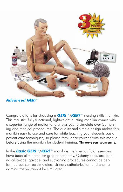
Congratulations for choosing a GERi™/KERi™ nursing skills manikin. This realistic, fully functional, lightweight nursing manikin comes with a superior range of motion and allows you to simulate over 35 nurs-ing and medical procedures. The quality and simple design makes this manikin easy to use and care for while teaching your students basic patient care techniques, so please familiarize yourself with this manual before using the manikin for student training. three-year warranty.
In the Basic GERi™/KERi™ manikins the internal fluid reservoirs have been eliminated for greater economy. Ostomy care, oral and nasal lavage, gavage, and suctioning procedures cannot be per-formed but can be simulated. Urinary catheterization and enema administration cannot be simulated.
Advanced GERi™
LF04051(N)UShoulder Injection Site
LF04056(N)UUpper Arm
LF04089(N)UStoma Set
LF04059(N)UWrist
LF04077(N)UHand (Left)
LF04062(N)UUpper Leg
(Left)
LF04067(N)ULower Leg
LF04045(N)UFoot (Left)LF04076(N)U
Female Organs
LF04072UComplete Set Replacement Hardware
LF04046(N)UFoot (Right)
LF04069(N)UAnkle
LF04066(N)UUpper Leg
(Right)
LF04052(N)ULeg Injection
Site
LF04078(N)UHand (Right)
LF04058(N)UForearm
LF04057(N)UElbow
LF04051(N)UShoulder
Injection Site
LF04085UDentures
LF04086UKeriTM Female Wig
LF04087UGeriTM Female Wig
LF04061(N)UHip
LF04082(N)UHip
Injection Site
LF04075(N)UMale Organs
LF04060(N)UHip Joint (Left)
LF04065(N)UHip Joint (Right)
LF04055(N)UShoulder (Left)
LF04070(N)UKeriTM Upper
Torso
LF04047(N)UGeriTM Upper
Torso
LF04083(N)UKeriTM Head
LF04088(N)UGeriTM Head
LF04073(N)UKeriTM Lower
Torso
LF04048(N)UGeriTM Lower
Torso
LF04063(N)URight Shoulder Joint
LF04054(N)ULeft Shoulder
Joint
LF04064(N)UShoulder (Right) LF04092(N)U
Complete Left Arm
LF03136URegular Pupil
LF03135UDialated Pupil
LF04090UHearing Aid
LF04093(N)UComplete Right Leg
Geri™/Keri™ The NursiNg skills MaNikiNComponent Replacement Parts
LF04091(N)UComplete Right
Arm
LF04094(N)UComplete Left Leg
Lavage,Gavage
NP 081-07 Geri/Keri Manikins.ind2 2 9/13/07 7:52:22 AM

Basic GERi™ LF04040UBasic KERi™ LF04021UList oF Components
Male genitaliaFemale genitaliaWigDenturesHearing Aid12 cc syringeREN cleanerLubricant spraySerial number — located under the
skin at the back of the neck
Advanced GERi™ LF04030UAdvanced KERi™ LF04022UList oF Components
Male genitaliaFemale genitaliaWigDenturesHearing Aid12 cc syringeREN cleanerLubricant sprayFluid drainage basinCatheter bag with fitting and pres-
sure sleeveRight iV training ArmLeft Blood pressure training ArmSerial number — located under the
skin at the back of the neck
VisUAL inspeCtion FeAtUResCancerous Mole ComparisonDecubitus Sacral Ulcer — Stage 1Dilated Pupil ComparisonSkin Wrinkles and FoldsElderly Appearance (GERi™ only)
1
Complete GERi™ LF04001UComplete KERi™ LF04020UList oF Components
Male genitaliaFemale genitaliaWigDenturesHearing Aid12 cc syringeREN cleanerLubricant sprayFluid drainage basinCatheter bag with fitting and pres-
sure sleeveSerial number — located under the
skin at the back of the neck
Auscultation GERi™ LF04003UAuscultation KERi™ LF04024UList oF Components
Male genitaliaFemale genitaliaWigDenturesHearing Aid12 cc syringeREN cleanerLubricant sprayFluid drainage basinCatheter bag with fitting and pres-
sure sleevesmart scope™ with single and dual
headpiecesRemote Control with LCD
displaytwo “AA” and two “AAA” batteriesSerial number — located under the
skin at the back of the neck
pAtient CARe simULAtionBandaging Finger and Toe — Flexible
and Individually MoldedBandaging and Wound DressingBed BathsBlood Pressure Arm Attachment
(optional on Basic, Complete, and Auscultation)
Clothing ChangesDenture Removal — Upper and
Lower
the Remote ContRoL CAn Be pRogRAmmeD to these heARt ConDitions:
01 Normal
02 Aortic regurgitation
03 Pulmonary stenosis
04 Mitral stenosis
05 Holosystolic
06 Mid-systolic
07 S3 Gallop
08 S4 Gallop
09 Systolic click
10 Atrial septal defect
11 PDA
12 VSD
the Remote ContRoL CAn Be pRogRAmmeD to these LUng ConDitions:
01 Normal lung
02 Normal Vesicular
03 Wheezes
04 Mono wheeze
05 Fine crackle
06 Coarse crackle
07 Ronchi crackle
08 Stridor
09 Cavernous
10 Bronchovesicular
11 Bronchial
12 Pulmonary edema
13 Infant
14 Friction rub
15 Egophony
16 Pectoriloquy
ConsULt the enCLoseD LAminAteD CARD FoR LUng AnD heARt soUnD site LoCAtions
To listen to the selected sounds, place the earpieces in ears angled in a for-ward position. Place the diaphragm of the SmartScope™ over one of the appropriate sites on the manikin (see diagram on back).
As an alternative, an amplified speaker (SB20146U) can be used allowing an entire classroom to hear at the same time. To connect the speaker, plug the speaker cord into the speaker jack on the top of the SmartScope™ box. When a speaker is connected to the SmartScope™, the ear pieces will not work. Place the diaphragm of the SmartScope™ over the appropriate sites on the manikin.
Note: The remote has a battery saver that shuts the unit down after eight min-utes if the remote is left on the same setting. To prevent if from shutting down, select a different heart or lung sound within the eight minute period of time.
AVAiLABLe sUppLies
LF01144U Additional SmartScope™
LF01148U Replacement Remote Control
sB20146U Amplified Speaker
16
NP 081-07 Geri/Keri Manikins.ind3 3 9/13/07 7:52:22 AM

Enema Administration — FemaleEye IrrigationGastrostomy Care, Lavage, Gavage
(only on Complete, Advanced, and Auscultation)
Hair Care — Washing, CombingHearing Aid Removal and Insertion
TechniquesInjection Sites — 4 IntramuscularIntramuscular Injection Sites — Arms,
Thigh, and ButtockIV Arm Attachment (optional
on Basic, Complete, and Auscultation)
Oral HygieneOstomy Care — Ileostomy and
Colostomy, Lavage and Suctioning
Pap Smears and Douching Patient Positioning — Superior Range
of MotionPatient Transfer TechniquesProstate Exam — Stage B — MaleTracheostomy Care — Lavage and
SuctioningUrinary Catheterization — Female
and Male (Uncircumcised)
sUpeRioR RAnge oF motionGERi™/KERi™ manikins offer the most complete and realistic range of motion with no pinch points. This allows for correct patient positioning. The manikin’s articulation includes:trunk — rotation, hyperextensionshoulder — abduction, adduction,
rotation, hyperextensionelbow — extension, flexion, pronation,
supinationWrist — flexion, hyperextension, radial
flexion, ulnar flexionFingers — abduction, adduction,
flexion (soft, lifelike material)neck — rotation, hyperextension,
lateral flexionhip — abduction, adduction, rotation,
hyperextensionKnee — extension, flexionAnkle — eversion, inversion, dorsiflexion,
plantarflexiontoes — abduction, adduction, flexion
(soft, lifelike material)
ARmsArms can be removed by bending the elbows backward approximately 90˚ to align the keyholes at the shoulders, pull outward away from shoulder of the manikin. Reverse this procedure to reas-semble. (See figure 1.)
LegsThe legs detach from the body at the hips by bending the legs backward approximately 150˚ so that the feet are near the shoulders and the keyholes are aligned. The legs can now be pulled outward away from the body. Reverse these procedures to reassemble. (See figure 2.)
heADThe head may be removed by rotating it 180˚ backwards to align with the key-holes, and pull up. Reverse this proce-dure to reassemble.JointsAll other joints may be disassembled with a flat-head screwdriver. Hold the opposite end of the connector pin to prevent unproductive rotation.
Figure 1
Figure 2
152
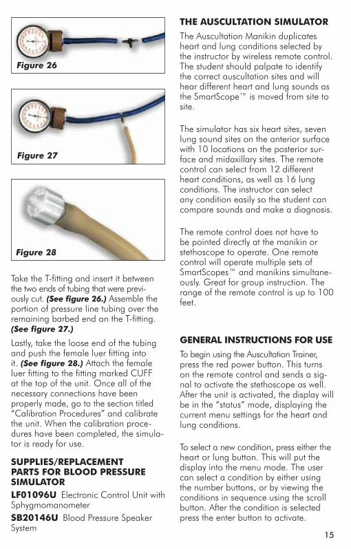
Take the T-fitting and insert it between the two ends of tubing that were previ-ously cut. (See figure 26.) Assemble the portion of pressure line tubing over the remaining barbed end on the T-fitting. (See figure 27.)
Lastly, take the loose end of the tubing and push the female luer fitting into it. (See figure 28.) Attach the female luer fitting to the fitting marked CUFF at the top of the unit. Once all of the necessary connections have been properly made, go to the section titled “Calibration Procedures” and calibrate the unit. When the calibration proce-dures have been completed, the simula-tor is ready for use.
sUppLies/RepLACement pARts FoR BLooD pRessURe simULAtoRLF01096U Electronic Control Unit with SphygmomanometersB20146U Blood Pressure Speaker System
Figure 26
Figure 27
Figure 28
the AUsCULtAtion simULAtoR
The Auscultation Manikin duplicates heart and lung conditions selected by the instructor by wireless remote control. The student should palpate to identify the correct auscultation sites and will hear different heart and lung sounds as the SmartScope™ is moved from site to site.
The simulator has six heart sites, seven lung sound sites on the anterior surface with 10 locations on the posterior sur-face and midaxillary sites. The remote control can select from 12 different heart conditions, as well as 16 lung conditions. The instructor can select any condition easily so the student can compare sounds and make a diagnosis.
The remote control does not have to be pointed directly at the manikin or stethoscope to operate. One remote control will operate multiple sets of SmartScopes™ and manikins simultane-ously. Great for group instruction. The range of the remote control is up to 100 feet.
geneRAL instRUCtions FoR Use
To begin using the Auscultation Trainer, press the red power button. This turns on the remote control and sends a sig-nal to activate the stethoscope as well. After the unit is activated, the display will be in the “status” mode, displaying the current menu settings for the heart and lung conditions.
To select a new condition, press either the heart or lung button. This will put the display into the menu mode. The user can select a condition by either using the number buttons, or by viewing the conditions in sequence using the scroll button. After the condition is selected press the enter button to activate.
NP 081-07 Geri/Keri Manikins.ind4 4 9/13/07 7:52:27 AM
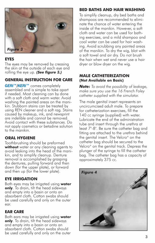
Figure 3
eyesThe eyes may be removed by creasing the skin at the outside of each eye and rolling the eye up. (See figure 3.)
geneRAL instRUCtion FoR CAReGERi™/KERi™ comes completely assembled and is simple to take apart if needed. Most cleaning can by done with a soft cloth and warm water. Avoid washing the painted areas on the mani-kin. Stubborn stains can be treated by using REN cleaner and a soft rag. Stains caused by makeup, ink, and newsprint are indelible and cannot be removed. Avoid contact with these substances. Do not apply cosmetics or betadine solution to the manikin.
oRAL hygieneToothbrushing should be preformed without water or any cleaning agents to avoid leaking into the head of the mani-kin, and to simplify cleanup. Denture removal is accomplished by grasping the dentures, pulling forward and then down (for the upper plate), or forward and then up (for the lower plate).
eye iRRigAtionBoth eyes may be irrigated using water only. To drain, tilt the head sideways and empty into a basin or onto an absorbent cloth. Cotton swabs should be used carefully and only on the outer ear.
eAR CAReBoth ears may be irrigated using water only. To drain, tilt the head sideways and empty into a basin or onto an absorbent cloth. Cotton swabs should be used carefully and only on the outer
BeD BAths AnD hAiR WAshingTo simplify cleanup, dry bed baths and shampoos are recommended to elimi-nate the chance of water entering the inside of the manikin. However, a soft cloth and water can be used for bath-ing exercises, and a mild shampoo and cool water can be used for hair wash-ing. Avoid scrubbing any painted areas of the manikin. To dry the wig, blot with a soft towel and air dry. Do not brush the hair when wet and never use a hair dryer or blow dryer on the wig.
mALe CAtheteRizAtion (not Available on Basic)
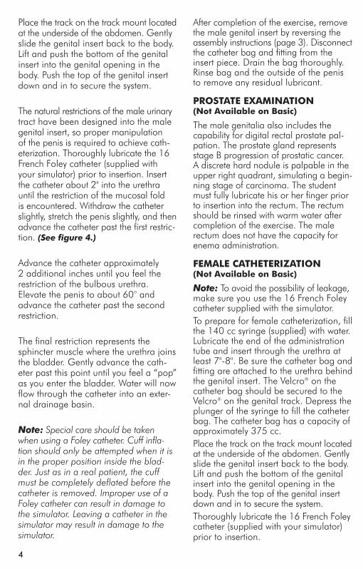
Note: To avoid the possibility of leakage, make sure you use the 16 French Foley catheter supplied with the simulator.
The male genital insert represents an uncircumcised adult male. To prepare for catheterization exercises, fill the 140 cc syringe (supplied) with water. Lubricate the end of the administration tube and insert through the urethra at least 7"-8". Be sure the catheter bag and fitting are attached to the urethra behind the genital insert. The Velcro® on the catheter bag should be secured to the Velcro® on the genital track. Depress the plunger of the syringe to fill the catheter bag. The catheter bag has a capacity of approximately 375 cc.
Figure 4
314
The Nasco Blood Pressure Simulator is programmed to demon-strate the five Korotkoff phases, includ-ing an auscultatory gap, which can be heard during auscultation of a subject, while measuring the subject’s blood pressure. Each is distinctly different and present for only a portion of the mea-surement sequence.
LoW BAtteRy inDiCAtoR
When the battery supply diminishes to a level near the point that the unit will no longer function properly, the “low batt” segment of the systolic pressure display will activate when the pressure in the sphygmomanometer cuff reaches above 20 mmHg. At this point, the batter-ies should be replaced as soon as pos-sible in order to insure proper operation of the unit. Refer to the section titled “Installing the Batteries.”
CALiBRAtion pRoCeDURes
To calibrate the simulator, set the unit up as described in the section titled “Using The Blood Pressure Simulator.” Apply the cuff to the simulated arm. Set the control box systolic pressure to 150 mmHg and set the diastolic pres-sure to 70 mmHg. Proceed with a simulated blood pressure measurement. Note the discrepancy in the readings between the gauge and the control box. Set the systolic “offset.” example: If the blood pressure reading was taken and the sounds started at 148 mmHg, then the offset is +2. If the sounds started at 152 mmHg, the offset is –2. For this example, assume that the sounds started at 148 mmHg. Press and hold the Calibration key until the systolic cor-rection window appears. (See figure 23.) Using the arrow up key set the cor-rection to +2. Set the diastolic offset. example: If the blood pressure read-ing was taken and the sounds stopped at 72 mmHg, the offset is –2; or if the sounds stopped at 68 mmHg, the offset is +2.
For this example, assume that the sounds stopped at 72 mmHg. From the systolic window, press the Menu key to change the diastolic window. (See figure 24.) With the arrow down key, set the correction to –2. Press the Menu key again and the message “CALIBRATION COMPLETE” will appear. The main menu window will be displayed.
pRepARing yoUR eqUipment FoR Use With the nAsCo BLooD pRessURe simULAtoRTo adapt your sphygmomanometer for use with the simulator, it is first necessary to obtain the luer fitting and the T-fit-ting included with the simulator, which is also available through your Nasco catalog sales office. Using a wire cutting pliers or similar instrument, carefully cut the pressure line of the sphygmoma-nometer about 2" from the gauge. (See figure 25.)
Figure 24
Figure 23
Figure 25
NP 081-07 Geri/Keri Manikins.ind5 5 9/13/07 7:52:30 AM
Place the track on the track mount located at the underside of the abdomen. Gently slide the genital insert back to the body. Lift and push the bottom of the genital insert into the genital opening in the body. Push the top of the genital insert down and in to secure the system.
The natural restrictions of the male urinary tract have been designed into the male genital insert, so proper manipulation of the penis is required to achieve cath-eterization. Thoroughly lubricate the 16 French Foley catheter (supplied with your simulator) prior to insertion. Insert the catheter about 2" into the urethra until the restriction of the mucosal fold is encountered. Withdraw the catheter slightly, stretch the penis slightly, and then advance the catheter past the first restric-tion. (See figure 4.)
Advance the catheter approximately 2 additional inches until you feel the restriction of the bulbous urethra. Elevate the penis to about 60° and advance the catheter past the second restriction.
The final restriction represents the sphincter muscle where the urethra joins the bladder. Gently advance the cath-eter past this point until you feel a “pop” as you enter the bladder. Water will now flow through the catheter into an exter-nal drainage basin.
Note: Special care should be taken when using a Foley catheter. Cuff infla-tion should only be attempted when it is in the proper position inside the blad-der. Just as in a real patient, the cuff must be completely deflated before the catheter is removed. Improper use of a Foley catheter can result in damage to the simulator. Leaving a catheter in the simulator may result in damage to the simulator.
After completion of the exercise, remove the male genital insert by reversing the assembly instructions (page 3). Disconnect the catheter bag and fitting from the insert piece. Drain the bag thoroughly. Rinse bag and the outside of the penis to remove any residual lubricant.
pRostAte exAminAtion (not Available on Basic)
The male genitalia also includes the capability for digital rectal prostate pal-pation. The prostate gland represents stage B progression of prostatic cancer. A discrete hard nodule is palpable in the upper right quadrant, simulating a begin-ning stage of carcinoma. The student must fully lubricate his or her finger prior to insertion into the rectum. The rectum should be rinsed with warm water after completion of the exercise. The male rectum does not have the capacity for enema administration.
FemALe CAtheteRizAtion (not Available on Basic)
Note: To avoid the possibility of leakage, make sure you use the 16 French Foley catheter supplied with the simulator.To prepare for female catheterization, fill the 140 cc syringe (supplied) with water. Lubricate the end of the administration tube and insert through the urethra at least 7"-8". Be sure the catheter bag and fitting are attached to the urethra behind the genital insert. The Velcro® on the catheter bag should be secured to the Velcro® on the genital track. Depress the plunger of the syringe to fill the catheter bag. The catheter bag has a capacity of approximately 375 cc.Place the track on the track mount located at the underside of the abdomen. Gently slide the genital insert back to the body. Lift and push the bottom of the genital insert into the genital opening in the body. Push the top of the genital insert down and in to secure the system.Thoroughly lubricate the 16 French Foley catheter (supplied with your simulator) prior to insertion.
134
Figure 21
Figure 22
The arrow up and down keys also control the volume of the sounds that are present in the arm. From the main menu, press the up arrow key to increase the volume, press the down arrow key to decrease the volume. The volume levels can be adjusted from level 1 (the lowest volume) to level 7 (the highest volume).
Using the BLooD pRessURe simULAtoRFirst, verify that the pressure line tubing from the sphygmomanometer and the audio line coming from the simulated arm assembly are properly connected to the blood pressure simulator unit, as previously described in the set up pro-cedures. Apply the sphygmomanometer cuff and gauge to the simulated arm assembly in the usual manner. Apply the stethoscope to the simulated arm also in the usual manner. Set the systolic and diastolic controls to the desired levels. Select the auscultatory gap if desired. Finally, adjust the pulse rate control to the desired setting.
To proceed with the simulated blood pressure measurement, first close the valve on the sphygmomanometer bulb tightly and begin pumping air into the
cuff until the gauge reads higher than the preset systolic level chosen. Once this point is reached, loosen the valve on the bulb slightly to allow the gauge pressure reading to decrease slowly. While monitoring the arm assembly with the stethoscope, note the point on the sphygmomanometer gauge when the first Korotkoff sound is heard. This will be the systolic blood pressure. Allow the pressure in the cuff to continue to decrease until the point at which the last pulse is heard, noting the reading on the gauge. This is the diastolic blood pressure.
Compare the results of reading the systolic and diastolic blood pressures on the gauge with the respective set-tings on the simulator. If the readings were accurate they should compare favorably with the preset values. If the auscultatory gap had been selected, then an absence of an audible pulse would have been noticed during what would have been the phase 2 Korotkoff sound. It is this lack of an audible pulse that is considered an auscultatory gap. Note that in reality the auscultatory gap can be present in either the phase 1 or phase 2 Korotkoff sounds. If it is desired to demonstrate the sounds heard while measuring a subject’s blood pressure to the trainee or group of trainees, an auxiliary blood pressure speaker amplifier system is available (SB20146U). If the auxiliary speaker is used, the speaker is plugged into the EXT AUDIO AMP jack located next to the ARM output jack at the top of the unit. Adjust the volume control to increase the output of the auxiliary speaker amplifier, and proceed with the blood pressure measurement sequence as it would normally be per-formed except that the stethoscope need not be used. Instead, listen to the sounds as they emanate from the speak-er amplifier, noting the differences in the Korotkoff phases being presented.
NP 081-07 Geri/Keri Manikins.ind6 6 9/13/07 7:52:32 AM
Note: Special care should be taken when using a Foley catheter. Cuff infla-tion should only be attempted when it is in the proper position inside the blad-der. Just as in a real patient, the cuff must be completely deflated before the catheter is removed. Improper use of a Foley catheter can result in damage to the simulator. Leaving a catheter in the simulator may result in damage to the simulator.
enemA ADministRAtionEnema administration can be practiced on the female genital insert only. To pre-pare the manikin for enema exercises, be sure the enema reservoir is securely attached to the inside of the rectum.Position the manikin on its left side in the Simm’s Position. Lubricate the appli-cator liberally and gently insert through the anus. Administer water only into the rectum. To simplify cleanup, you may choose to leave the applicator in place while positioning the manikin over a drainage basin. The rectum will drain via gravity as soon as the manikin leaves the left Simm’s position. Be sure to have a basin under the manikin.Rinse the anus and internal rectal reser-voir to remove any residual lubricant.
DoUChing, pAp smeARs, AnD VAginAL inspeCtionThe female genitalia also allows for douching, but extreme care should be taken to lubricate the applicator thor-oughly. Only water should be used as a douching agent. Pap Smear procedures and visual inspection of the vagina and cervix may be demonstrated on GERi™/KERi™ but, again, extreme care should be taken to thoroughly lubricate any instrument of insertion. Use the smallest possible speculum and avoid exerting too much pressure on the vaginal walls. Overexertion will damage the simulator just as it would cause tissue damage in an actual patient. The speculum must be thoroughly lubricated prior to inser-tion. The vagina should be rinsed with warm water after completion of the exer-cise to remove any residual lubricant.
gAstRostomy CARe: LAVAge AnD gAVAgeA flanged hole simulating an abdominal incision for the insertion of a feeding tube is included on the upper torso for performing lavage and gavage. Inside the upper torso is a reservoir (bag) with a maximum capacity of 500 cc which is attached to the gastrostomy open-ing with a two-part coupler. The bag is removed by pushing in on the clear L-shaped button and pulling it straight away. To attach, simply push the coupler body (with bag attached) onto the cou-pler insert (part with a black O-ring) that is protruding from inside the torso. You will hear a slight snap when the con-nection is complete. With extensive use, these two coupler parts may no longer snap, so the clear L-shaped button will have to be manually pulled all the way out after connecting the two parts. Test the connection by pulling on the cou-pler body to ensure that it is locked. This gastrostomy feature is designed for use with a 16 French feeding tube. It is recommended that the tip of the feed-ing tube be lubricated before inserting. Make sure the reservoir is straight and flat before attempting to simulate actual feeding with a liquid.
ostomy CAReColostomy and ileostomy care can be practiced on GERi™/KERi™, includ-ing stoma dilation, irrigation, cleaning, and ostomy bag changing procedures. Irrigation tubes should be well lubri-cated prior to insertion, and the stomas should be rinsed with warm water after completion of the exercise to remove any residual lubricant. The fluid capacity of the stoma reservoirs is 20 cc. Removal of the internal stoma reservoirs can be achieved by removing the genitalia, and reaching through the genital cavity. The reservoir bags are attached directly to the underside of the stomas. To remove, pull the reservoir fittings down and disconnect from the stomas. Then pull the reservoir bags from the Velcro® attachments.
512
Figure 16
Figure 17
Figure 18
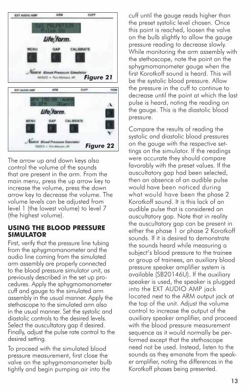
pALpABLe pULse FeAtUReThe Nasco Blood Pressure Simulator also incorporates a palpable pulse at the radial location. (See figure 20.) Palpations can be felt upon start-up of the unit or after blood pressure set-tings have been made. Press the Menu key repeatedly until “Set PALPATION” menu appears. “Pulse ON” is defaulted and enables the palpation feature. Palpations continue during inflation until the cuff pressure reaches the systolic set point, and resumes when the cuff pres-sure reaches the systolic set point during the deflation of the cuff.
A pulseless condition can be simulated by switching your unit to the “pulseless” mode. Press the Menu key repeatedly until “Set PALPATION” menu appears. By pressing the down arrow at this point, palpations can be disabled causing the
Figure 19
simulator to be pulseless. When in the “pulseless” mode, all settings are auto-matically reset to 0 and all blood pres-sure sounds are disabled.The pulseless setting will also turn off the sounds in the arm. The pulse will always be on unless the pulseless feature is activated or if the systolic or heart rate levels are set to zero. To do this, press the Menu key four times. The down arrow key will set the pulse to pulseless. Press the arrow up key to turn the pulse back on. (See figure 21.) Located to the right of the Menu key is the auscula-tory Gap key. (See figure 22.) This key is included to simulate the ausculatory gap that is sometimes present between phase 1 and phase 2 sounds in which no audible sound is noted during this portion of ausculation. This control func-tion is included so that the trainee can become familiar with this phenomenon.
Pressing the Gap key simply turns the gap function off or on. When the key is pressed, a message will briefly appear that the ausculatory gap is enabled or disabled. Also the main display will show (at the bottom right of the display) either AGap:Y (for on) or AGap:N (for off).
Figure 20
pulse Location
NP 081-07 Geri/Keri Manikins.ind7 7 9/13/07 7:52:33 AM
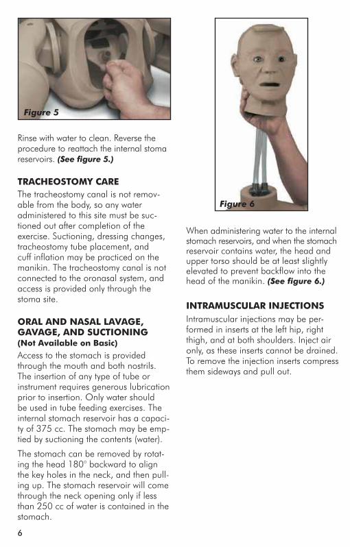
Figure 5
Rinse with water to clean. Reverse the procedure to reattach the internal stoma reservoirs. (See figure 5.)
tRACheostomy CAReThe tracheostomy canal is not remov-able from the body, so any water administered to this site must be suc-tioned out after completion of the exercise. Suctioning, dressing changes, tracheostomy tube placement, and cuff inflation may be practiced on the manikin. The tracheostomy canal is not connected to the oronasal system, and access is provided only through the stoma site.
oRAL AnD nAsAL LAVAge, gAVAge, AnD sUCtioning (not Available on Basic)
Access to the stomach is provided through the mouth and both nostrils. The insertion of any type of tube or instrument requires generous lubrication prior to insertion. Only water should be used in tube feeding exercises. The internal stomach reservoir has a capaci-ty of 375 cc. The stomach may be emp-tied by suctioning the contents (water).
The stomach can be removed by rotat-ing the head 180° backward to align the key holes in the neck, and then pull-ing up. The stomach reservoir will come through the neck opening only if less than 250 cc of water is contained in the stomach.
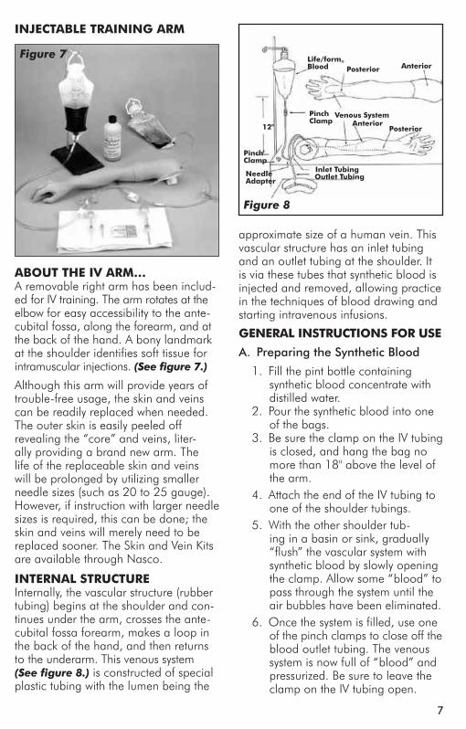
When administering water to the internal stomach reservoirs, and when the stomach reservoir contains water, the head and upper torso should be at least slightly elevated to prevent backflow into the head of the manikin. (See figure 6.)
intRAmUsCULAR inJeCtionsIntramuscular injections may be per-formed in inserts at the left hip, right thigh, and at both shoulders. Inject air only, as these inserts cannot be drained. To remove the injection inserts compress them sideways and pull out.
Figure 6
116
Install 6 “AA” batteries as indicated by the orientation diagram embossed in the bottom of the bracket. It is recommend-ed that alkaline batteries be used for increased battery life. After the batteries have been properly installed, reassemble the Blood Pressure Simulator by simply reversing the disassembly procedures. Place the unit face up on the work sur-face and turn it on by pressing the on/off switch on the top right of the unit. (See figure 13.) Observe the display and verify that a readable display is present, indicat-ing proper battery installation.
Note: The control box has a battery saving feature which will turn the unit off after about 8-10 minutes if no keys are used within that period of time.
The next step is to connect the simu-lated arm and speaker assembly along with the sphygmomanometer cuff and gauge assembly included with the unit. First, locate the end of the pressure line attached to the sphygmomanometer that has the female luer fitting attached to it. Attach this to the male luer fitting at the top of the unit marked CUFF. (See figure 14.) After the pressure line fitting has been properly installed, locate the plug that is at the end of the wire which extends from the simulated arm assembly. Insert the plug from the arm into the jack at the top of the unit marked ARM. (See figure 15.)
At this point the Blood Pressure Simulator is ready for use. The unit has been facto-ry calibrated for use with the accessories included in the kit. No further calibra-tion adjustments should be necessary at this time. If the unit is to be used with a sphygmomanometer other than that supplied with the unit, or if recalibration is necessary at a later date, then see the section titled “Calibration Procedures.”
on/oFFsWitCh
Figure 13
Figure 14
Figure 15
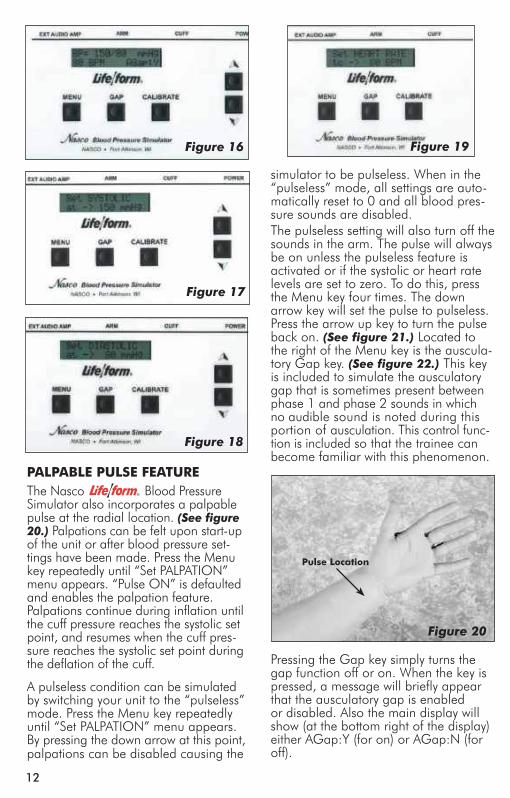
FAmiLiARizing yoURseLF With the nAsCo BLooD pRessURe simULAtoR ContRoL pAneLUnder the display window are three buttons: Menu, Gap, and Calibrate. (See figure 16.) The systolic pressure is set by pressing the Menu key once. The pressure is adjusted up or down using the up or down arrow keys. (See figure 17.) The diastolic pressure is set by pressing the Menu key a second time. Adjust the set-ting up and down with the arrow up or down keys. (See figure 18.) The heart rate is set by pressing the Menu key a third time, and adjusting the rate with the arrow up and down keys. The pulse rate can be set from 0 beats per minute to 300 beats per minute. (See figure 19.) The palpation can be set to either on or pulseless. When the pulseless set-ting is used, the diastolic and systolic pressures will automatically be set to 0.
NP 081-07 Geri/Keri Manikins.ind8 8 9/13/07 7:52:37 AM
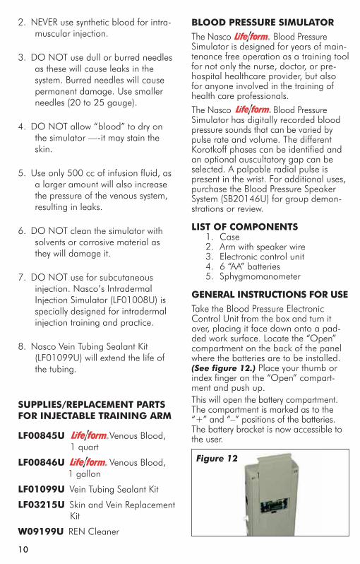
ABoUt the iV ARm…A removable right arm has been includ-ed for IV training. The arm rotates at the elbow for easy accessibility to the ante-cubital fossa, along the forearm, and at the back of the hand. A bony landmark at the shoulder identifies soft tissue for intramuscular injections. (See figure 7.)
Although this arm will provide years of trouble-free usage, the skin and veins can be readily replaced when needed. The outer skin is easily peeled off revealing the “core” and veins, liter-ally providing a brand new arm. The life of the replaceable skin and veins will be prolonged by utilizing smaller needle sizes (such as 20 to 25 gauge). However, if instruction with larger needle sizes is required, this can be done; the skin and veins will merely need to be replaced sooner. The Skin and Vein Kits are available through Nasco.
inteRnAL stRUCtURe Internally, the vascular structure (rubber tubing) begins at the shoulder and con-tinues under the arm, crosses the ante-cubital fossa forearm, makes a loop in the back of the hand, and then returns to the underarm. This venous system (See figure 8.) is constructed of special plastic tubing with the lumen being the
pinchClamp
outlet tubinginlet tubing
pinch Clamp
12"
Life/form® Blood
Venous systemAnterior
posterior
needleAdapter
posterior Anterior
approximate size of a human vein. This vascular structure has an inlet tubing and an outlet tubing at the shoulder. It is via these tubes that synthetic blood is injected and removed, allowing practice in the techniques of blood drawing and starting intravenous infusions.
geneRAL instRUCtions FoR Use
A. Preparing the Synthetic Blood
1. Fill the pint bottle containing synthetic blood concentrate with distilled water.
2. Pour the synthetic blood into one of the bags.
3. Be sure the clamp on the IV tubing is closed, and hang the bag no more than 18" above the level of the arm.
4. Attach the end of the IV tubing to one of the shoulder tubings.
5. With the other shoulder tub-ing in a basin or sink, gradually “flush” the vascular system with synthetic blood by slowly opening the clamp. Allow some “blood” to pass through the system until the air bubbles have been eliminated.
6. Once the system is filled, use one of the pinch clamps to close off the blood outlet tubing. The venous system is now full of “blood” and pressurized. Be sure to leave the clamp on the IV tubing open.
inJeCtABLe tRAining ARm
Figure 7
Figure 8
710
2. NEVER use synthetic blood for intra-muscular injection.
3. DO NOT use dull or burred needles as these will cause leaks in the system. Burred needles will cause permanent damage. Use smaller needles (20 to 25 gauge).
4. DO NOT allow “blood” to dry on the simulator —-it may stain the skin.
5. Use only 500 cc of infusion fluid, as a larger amount will also increase the pressure of the venous system, resulting in leaks.
6. DO NOT clean the simulator with solvents or corrosive material as they will damage it.
7. DO NOT use for subcutaneous injection. Nasco’s Intradermal Injection Simulator (LF01008U) is specially designed for intradermal injection training and practice.
8. Nasco Vein Tubing Sealant Kit (LF01099U) will extend the life of the tubing.
sUppLies/RepLACement pARts FoR inJeCtABLe tRAining ARm
LF00845U Venous Blood, 1 quart
LF00846U Venous Blood, 1 gallon
LF01099U Vein Tubing Sealant Kit
LF03215U Skin and Vein Replacement Kit
W09199U REN Cleaner
BLooD pRessURe simULAtoRThe Nasco Blood Pressure Simulator is designed for years of main-tenance free operation as a training tool for not only the nurse, doctor, or pre-hospital healthcare provider, but also for anyone involved in the training of health care professionals.
The Nasco Blood Pressure Simulator has digitally recorded blood pressure sounds that can be varied by pulse rate and volume. The different Korotkoff phases can be identified and an optional auscultatory gap can be selected. A palpable radial pulse is present in the wrist. For additional uses, purchase the Blood Pressure Speaker System (SB20146U) for group demon-strations or review.
List oF Components 1. Case 2. Arm with speaker wire 3. Electronic control unit 4. 6 “AA” batteries 5. Sphygmomanometer
geneRAL instRUCtions FoR Use Take the Blood Pressure Electronic Control Unit from the box and turn it over, placing it face down onto a pad-ded work surface. Locate the “Open” compartment on the back of the panel where the batteries are to be installed. (See figure 12.) Place your thumb or index finger on the “Open” compart-ment and push up.This will open the battery compartment. The compartment is marked as to the “+” and “–” positions of the batteries. The battery bracket is now accessible to the user.
Figure 12
NP 081-07 Geri/Keri Manikins.ind9 9 9/13/07 7:52:39 AM

7. After filling the venous system according to instructions, the arm is now ready for you to practice drawing blood. Blood can be drawn anywhere along the pathway of the vein. Distilled water, rather than alcohol, should be used to prepare the sites. Synthetic blood will actually be aspirated once the vein is prop-erly punctured.
8. Small diameter needles (20 to 25 gauge) should be used.
B. Preparing the Arm for Intravenous Infusions
1. Close the clamp at the end of IV bag A tube, then fill with water (distilled water is recommended), and hang not more than 18" above the arm. (See figure 9.)
2. Appropriate intravenous infusion needles (or butterflies) should be used; distilled water is recom-mended as an infusion.
3. IVs can be started anywhere along the pathway of the simulated vein. Cleanse the sites with distilled water only.
4. Attach the adapter end of the IV tubing into one of the shoulder tubing ends.
Figure 9
5. Place the other shoulder tub-ing end in a basin or jar, and “flush” the vascular system by opening the clamp. Allow infusion (water) to pass through the system until air bubbles are eliminated. Shut off the flow with a pinch clamp. The venous system is now full and pressurized.
6. Insert an IV needle or butterfly in the vein. “Flashback” will indicate proper insertion.
7. Close the clamp on IV bag A tube and remove pinch clamp from shoulder tubing.
8. Attach latex needle adapter to IV needle and IV tubing. (See figure 10.)
Proof of proper procedure will then be evidenced by the flow of infusion fluid from IV bag B. Control flow rate with clamp on IV set B. This fluid can be used over. If more realistic experience is desired with “blood flashback” instead of water when inserting butterfly into lumen of vein, use next procedure C.
Figure 10
Figure 11
98
C. Recommended Procedure for Simultaneous IV Infusions and Drawing Blood
Using two IV bag kits, hook up and install with IV bag A and IV bag B. (See figure 11.) Remove air vent from bag B.
1. Begin with synthetic blood in IV bag.
2. Open clamps on both A and B to pressurize system. “Flush” system by allowing “blood” to flow into container B until bubbles in tubing disappear, then regulate blood flow from bag A (using clamp). System is now full of “blood” and pressurized. “Blood” can now be drawn anywhere along the path-way of the vein.
3. Intravenous infusion — insert but-terfly into lumen of vein. Proof of correct insertion is evidenced by flashback of “blood.” Insert end of IV tubing into butterfly. Adjust flow to desirable rate with clamp. With this arrangement the IV bag B, when full, may be easily switched with A.
Note: Always regulate flow of “blood” from the raised bag, and open the other clamp.
D. Intramuscular InjectionsThe procedure for administering intra-muscular injections can be practiced in the area of the deltoid. Prep the site with distilled water only. These injections can be done utilizing the appropriate needle and syringe. 1/2 cc of distilled water may be injected, however, we recommend utilizing air as injectant since the dis-tilled water cannot be drained, but must evaporate from the arm. Synthetic blood must NEVER be used for injections.
tRoUBLeshootingIf “blood” cannot be aspirated during the blood drawing procedure: 1. The clamp is not opened.
2. There are kinks in the tubing of IV sets.
3. Tubing has been pinched shut by constant pressure of pinch clamps. Lumen remains pinched occasion-ally even if pinch clamps are loos-ened. Slide clamp to new position and with fingers manipulate tubing at pinched site to restore lumen. In heavy use, slide clamp to new position on tubing from time to time to prevent the “permanent pinch” caused by constant clamp pressure. Replace IV kit.
4. If these measures do not unclog the venous system, try using a large 50 cc syringe to force fluid through the tubing.
5. If none of these measures work, peel back the skin (soap up arm and skin generously with Ivory® liquid detergent) of the arm to the knuck-les (do not remove from fingers), and examine all tubing for possible kinks. Soap up arm and skin gener-ously with Ivory® liquid detergent, and return skin over arm.
CARe oF simULAtoRAfter each class use, disconnect “blood” and flush the venous system. Return synthetic blood to the storage bottle. Remove pinch clamps and IV sets from arm. Use tap water to flush the venous system and wash the outside of the arm with Ivory® liquid detergent and water. Excess water may be removed from the arm by raising the hand, lowering the shoulder, and draining it into a sink or basin. Always remove the pinch clamps from shoulder tubing and drain excess water from veins before storing.
CAUtions1. This synthetic blood is specially for-
mulated to be compatible with the self-sealing veins and plastics used in manufacturing the arm.
NP 081-07 Geri/Keri Manikins.ind10 10 9/13/07 7:52:40 AM
ABoUt the iV ARm…A removable right arm has been includ-ed for IV training. The arm rotates at the elbow for easy accessibility to the ante-cubital fossa, along the forearm, and at the back of the hand. A bony landmark at the shoulder identifies soft tissue for intramuscular injections. (See figure 7.)
Although this arm will provide years of trouble-free usage, the skin and veins can be readily replaced when needed. The outer skin is easily peeled off revealing the “core” and veins, liter-ally providing a brand new arm. The life of the replaceable skin and veins will be prolonged by utilizing smaller needle sizes (such as 20 to 25 gauge). However, if instruction with larger needle sizes is required, this can be done; the skin and veins will merely need to be replaced sooner. The Skin and Vein Kits are available through Nasco.
inteRnAL stRUCtURe Internally, the vascular structure (rubber tubing) begins at the shoulder and con-tinues under the arm, crosses the ante-cubital fossa forearm, makes a loop in the back of the hand, and then returns to the underarm. This venous system (See figure 8.) is constructed of special plastic tubing with the lumen being the
pinchClamp
outlet tubinginlet tubing
pinch Clamp
12"
Life/form® Blood
Venous systemAnterior
posterior
needleAdapter
posterior Anterior
approximate size of a human vein. This vascular structure has an inlet tubing and an outlet tubing at the shoulder. It is via these tubes that synthetic blood is injected and removed, allowing practice in the techniques of blood drawing and starting intravenous infusions.
geneRAL instRUCtions FoR Use
A. Preparing the Synthetic Blood
1. Fill the pint bottle containing synthetic blood concentrate with distilled water.
2. Pour the synthetic blood into one of the bags.
3. Be sure the clamp on the IV tubing is closed, and hang the bag no more than 18" above the level of the arm.
4. Attach the end of the IV tubing to one of the shoulder tubings.
5. With the other shoulder tub-ing in a basin or sink, gradually “flush” the vascular system with synthetic blood by slowly opening the clamp. Allow some “blood” to pass through the system until the air bubbles have been eliminated.
6. Once the system is filled, use one of the pinch clamps to close off the blood outlet tubing. The venous system is now full of “blood” and pressurized. Be sure to leave the clamp on the IV tubing open.
inJeCtABLe tRAining ARm
Figure 7
Figure 8
710
2. NEVER use synthetic blood for intra-muscular injection.
3. DO NOT use dull or burred needles as these will cause leaks in the system. Burred needles will cause permanent damage. Use smaller needles (20 to 25 gauge).
4. DO NOT allow “blood” to dry on the simulator —-it may stain the skin.
5. Use only 500 cc of infusion fluid, as a larger amount will also increase the pressure of the venous system, resulting in leaks.
6. DO NOT clean the simulator with solvents or corrosive material as they will damage it.
7. DO NOT use for subcutaneous injection. Nasco’s Intradermal Injection Simulator (LF01008U) is specially designed for intradermal injection training and practice.
8. Nasco Vein Tubing Sealant Kit (LF01099U) will extend the life of the tubing.
sUppLies/RepLACement pARts FoR inJeCtABLe tRAining ARm
LF00845U Venous Blood, 1 quart
LF00846U Venous Blood, 1 gallon
LF01099U Vein Tubing Sealant Kit
LF03215U Skin and Vein Replacement Kit
W09199U REN Cleaner
BLooD pRessURe simULAtoRThe Nasco Blood Pressure Simulator is designed for years of main-tenance free operation as a training tool for not only the nurse, doctor, or pre-hospital healthcare provider, but also for anyone involved in the training of health care professionals.
The Nasco Blood Pressure Simulator has digitally recorded blood pressure sounds that can be varied by pulse rate and volume. The different Korotkoff phases can be identified and an optional auscultatory gap can be selected. A palpable radial pulse is present in the wrist. For additional uses, purchase the Blood Pressure Speaker System (SB20146U) for group demon-strations or review.
List oF Components 1. Case 2. Arm with speaker wire 3. Electronic control unit 4. 6 “AA” batteries 5. Sphygmomanometer
geneRAL instRUCtions FoR Use Take the Blood Pressure Electronic Control Unit from the box and turn it over, placing it face down onto a pad-ded work surface. Locate the “Open” compartment on the back of the panel where the batteries are to be installed. (See figure 12.) Place your thumb or index finger on the “Open” compart-ment and push up.This will open the battery compartment. The compartment is marked as to the “+” and “–” positions of the batteries. The battery bracket is now accessible to the user.
Figure 12
NP 081-07 Geri/Keri Manikins.ind9 9 9/13/07 7:52:39 AM
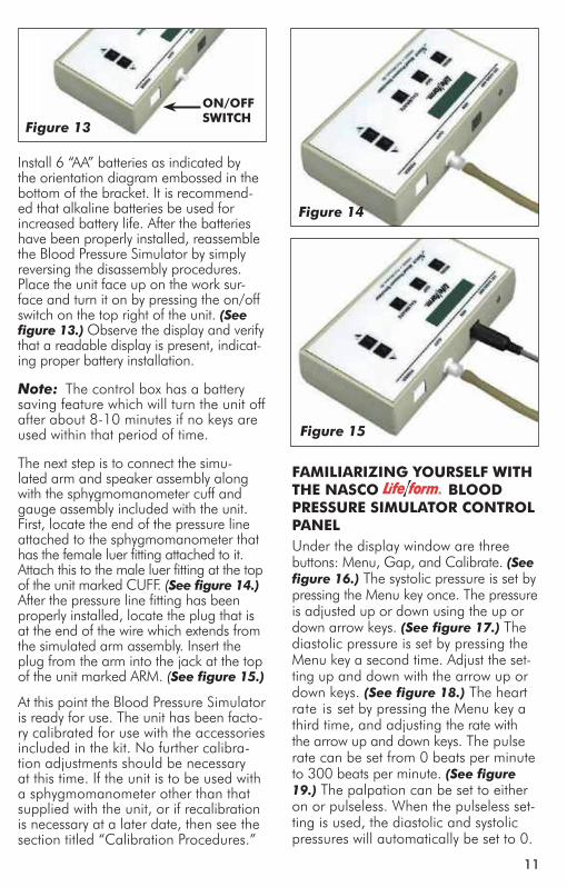
Figure 5
Rinse with water to clean. Reverse the procedure to reattach the internal stoma reservoirs. (See figure 5.)
tRACheostomy CAReThe tracheostomy canal is not remov-able from the body, so any water administered to this site must be suc-tioned out after completion of the exercise. Suctioning, dressing changes, tracheostomy tube placement, and cuff inflation may be practiced on the manikin. The tracheostomy canal is not connected to the oronasal system, and access is provided only through the stoma site.
oRAL AnD nAsAL LAVAge, gAVAge, AnD sUCtioning (not Available on Basic)
Access to the stomach is provided through the mouth and both nostrils. The insertion of any type of tube or instrument requires generous lubrication prior to insertion. Only water should be used in tube feeding exercises. The internal stomach reservoir has a capaci-ty of 375 cc. The stomach may be emp-tied by suctioning the contents (water).
The stomach can be removed by rotat-ing the head 180° backward to align the key holes in the neck, and then pull-ing up. The stomach reservoir will come through the neck opening only if less than 250 cc of water is contained in the stomach.
When administering water to the internal stomach reservoirs, and when the stomach reservoir contains water, the head and upper torso should be at least slightly elevated to prevent backflow into the head of the manikin. (See figure 6.)
intRAmUsCULAR inJeCtionsIntramuscular injections may be per-formed in inserts at the left hip, right thigh, and at both shoulders. Inject air only, as these inserts cannot be drained. To remove the injection inserts compress them sideways and pull out.
Figure 6
116
Install 6 “AA” batteries as indicated by the orientation diagram embossed in the bottom of the bracket. It is recommend-ed that alkaline batteries be used for increased battery life. After the batteries have been properly installed, reassemble the Blood Pressure Simulator by simply reversing the disassembly procedures. Place the unit face up on the work sur-face and turn it on by pressing the on/off switch on the top right of the unit. (See figure 13.) Observe the display and verify that a readable display is present, indicat-ing proper battery installation.
Note: The control box has a battery saving feature which will turn the unit off after about 8-10 minutes if no keys are used within that period of time.
The next step is to connect the simu-lated arm and speaker assembly along with the sphygmomanometer cuff and gauge assembly included with the unit. First, locate the end of the pressure line attached to the sphygmomanometer that has the female luer fitting attached to it. Attach this to the male luer fitting at the top of the unit marked CUFF. (See figure 14.) After the pressure line fitting has been properly installed, locate the plug that is at the end of the wire which extends from the simulated arm assembly. Insert the plug from the arm into the jack at the top of the unit marked ARM. (See figure 15.)
At this point the Blood Pressure Simulator is ready for use. The unit has been facto-ry calibrated for use with the accessories included in the kit. No further calibra-tion adjustments should be necessary at this time. If the unit is to be used with a sphygmomanometer other than that supplied with the unit, or if recalibration is necessary at a later date, then see the section titled “Calibration Procedures.”
on/oFFsWitCh
Figure 13
Figure 14
Figure 15
FAmiLiARizing yoURseLF With the nAsCo BLooD pRessURe simULAtoR ContRoL pAneLUnder the display window are three buttons: Menu, Gap, and Calibrate. (See figure 16.) The systolic pressure is set by pressing the Menu key once. The pressure is adjusted up or down using the up or down arrow keys. (See figure 17.) The diastolic pressure is set by pressing the Menu key a second time. Adjust the set-ting up and down with the arrow up or down keys. (See figure 18.) The heart rate is set by pressing the Menu key a third time, and adjusting the rate with the arrow up and down keys. The pulse rate can be set from 0 beats per minute to 300 beats per minute. (See figure 19.) The palpation can be set to either on or pulseless. When the pulseless set-ting is used, the diastolic and systolic pressures will automatically be set to 0.
NP 081-07 Geri/Keri Manikins.ind8 8 9/13/07 7:52:37 AM
Note: Special care should be taken when using a Foley catheter. Cuff infla-tion should only be attempted when it is in the proper position inside the blad-der. Just as in a real patient, the cuff must be completely deflated before the catheter is removed. Improper use of a Foley catheter can result in damage to the simulator. Leaving a catheter in the simulator may result in damage to the simulator.
enemA ADministRAtionEnema administration can be practiced on the female genital insert only. To pre-pare the manikin for enema exercises, be sure the enema reservoir is securely attached to the inside of the rectum.Position the manikin on its left side in the Simm’s Position. Lubricate the appli-cator liberally and gently insert through the anus. Administer water only into the rectum. To simplify cleanup, you may choose to leave the applicator in place while positioning the manikin over a drainage basin. The rectum will drain via gravity as soon as the manikin leaves the left Simm’s position. Be sure to have a basin under the manikin.Rinse the anus and internal rectal reser-voir to remove any residual lubricant.
DoUChing, pAp smeARs, AnD VAginAL inspeCtionThe female genitalia also allows for douching, but extreme care should be taken to lubricate the applicator thor-oughly. Only water should be used as a douching agent. Pap Smear procedures and visual inspection of the vagina and cervix may be demonstrated on GERi™/KERi™ but, again, extreme care should be taken to thoroughly lubricate any instrument of insertion. Use the smallest possible speculum and avoid exerting too much pressure on the vaginal walls. Overexertion will damage the simulator just as it would cause tissue damage in an actual patient. The speculum must be thoroughly lubricated prior to inser-tion. The vagina should be rinsed with warm water after completion of the exer-cise to remove any residual lubricant.
gAstRostomy CARe: LAVAge AnD gAVAgeA flanged hole simulating an abdominal incision for the insertion of a feeding tube is included on the upper torso for performing lavage and gavage. Inside the upper torso is a reservoir (bag) with a maximum capacity of 500 cc which is attached to the gastrostomy open-ing with a two-part coupler. The bag is removed by pushing in on the clear L-shaped button and pulling it straight away. To attach, simply push the coupler body (with bag attached) onto the cou-pler insert (part with a black O-ring) that is protruding from inside the torso. You will hear a slight snap when the con-nection is complete. With extensive use, these two coupler parts may no longer snap, so the clear L-shaped button will have to be manually pulled all the way out after connecting the two parts. Test the connection by pulling on the cou-pler body to ensure that it is locked. This gastrostomy feature is designed for use with a 16 French feeding tube. It is recommended that the tip of the feed-ing tube be lubricated before inserting. Make sure the reservoir is straight and flat before attempting to simulate actual feeding with a liquid.
ostomy CAReColostomy and ileostomy care can be practiced on GERi™/KERi™, includ-ing stoma dilation, irrigation, cleaning, and ostomy bag changing procedures. Irrigation tubes should be well lubri-cated prior to insertion, and the stomas should be rinsed with warm water after completion of the exercise to remove any residual lubricant. The fluid capacity of the stoma reservoirs is 20 cc. Removal of the internal stoma reservoirs can be achieved by removing the genitalia, and reaching through the genital cavity. The reservoir bags are attached directly to the underside of the stomas. To remove, pull the reservoir fittings down and disconnect from the stomas. Then pull the reservoir bags from the Velcro® attachments.
512
Figure 16
Figure 17
Figure 18
pALpABLe pULse FeAtUReThe Nasco Blood Pressure Simulator also incorporates a palpable pulse at the radial location. (See figure 20.) Palpations can be felt upon start-up of the unit or after blood pressure set-tings have been made. Press the Menu key repeatedly until “Set PALPATION” menu appears. “Pulse ON” is defaulted and enables the palpation feature. Palpations continue during inflation until the cuff pressure reaches the systolic set point, and resumes when the cuff pres-sure reaches the systolic set point during the deflation of the cuff.
A pulseless condition can be simulated by switching your unit to the “pulseless” mode. Press the Menu key repeatedly until “Set PALPATION” menu appears. By pressing the down arrow at this point, palpations can be disabled causing the
Figure 19
simulator to be pulseless. When in the “pulseless” mode, all settings are auto-matically reset to 0 and all blood pres-sure sounds are disabled.The pulseless setting will also turn off the sounds in the arm. The pulse will always be on unless the pulseless feature is activated or if the systolic or heart rate levels are set to zero. To do this, press the Menu key four times. The down arrow key will set the pulse to pulseless. Press the arrow up key to turn the pulse back on. (See figure 21.) Located to the right of the Menu key is the auscula-tory Gap key. (See figure 22.) This key is included to simulate the ausculatory gap that is sometimes present between phase 1 and phase 2 sounds in which no audible sound is noted during this portion of ausculation. This control func-tion is included so that the trainee can become familiar with this phenomenon.
Pressing the Gap key simply turns the gap function off or on. When the key is pressed, a message will briefly appear that the ausculatory gap is enabled or disabled. Also the main display will show (at the bottom right of the display) either AGap:Y (for on) or AGap:N (for off).
Figure 20
pulse Location
NP 081-07 Geri/Keri Manikins.ind7 7 9/13/07 7:52:33 AM
Place the track on the track mount located at the underside of the abdomen. Gently slide the genital insert back to the body. Lift and push the bottom of the genital insert into the genital opening in the body. Push the top of the genital insert down and in to secure the system.
The natural restrictions of the male urinary tract have been designed into the male genital insert, so proper manipulation of the penis is required to achieve cath-eterization. Thoroughly lubricate the 16 French Foley catheter (supplied with your simulator) prior to insertion. Insert the catheter about 2" into the urethra until the restriction of the mucosal fold is encountered. Withdraw the catheter slightly, stretch the penis slightly, and then advance the catheter past the first restric-tion. (See figure 4.)
Advance the catheter approximately 2 additional inches until you feel the restriction of the bulbous urethra. Elevate the penis to about 60° and advance the catheter past the second restriction.
The final restriction represents the sphincter muscle where the urethra joins the bladder. Gently advance the cath-eter past this point until you feel a “pop” as you enter the bladder. Water will now flow through the catheter into an exter-nal drainage basin.
Note: Special care should be taken when using a Foley catheter. Cuff infla-tion should only be attempted when it is in the proper position inside the blad-der. Just as in a real patient, the cuff must be completely deflated before the catheter is removed. Improper use of a Foley catheter can result in damage to the simulator. Leaving a catheter in the simulator may result in damage to the simulator.
After completion of the exercise, remove the male genital insert by reversing the assembly instructions (page 3). Disconnect the catheter bag and fitting from the insert piece. Drain the bag thoroughly. Rinse bag and the outside of the penis to remove any residual lubricant.
pRostAte exAminAtion (not Available on Basic)
The male genitalia also includes the capability for digital rectal prostate pal-pation. The prostate gland represents stage B progression of prostatic cancer. A discrete hard nodule is palpable in the upper right quadrant, simulating a begin-ning stage of carcinoma. The student must fully lubricate his or her finger prior to insertion into the rectum. The rectum should be rinsed with warm water after completion of the exercise. The male rectum does not have the capacity for enema administration.
FemALe CAtheteRizAtion (not Available on Basic)
Note: To avoid the possibility of leakage, make sure you use the 16 French Foley catheter supplied with the simulator.To prepare for female catheterization, fill the 140 cc syringe (supplied) with water. Lubricate the end of the administration tube and insert through the urethra at least 7"-8". Be sure the catheter bag and fitting are attached to the urethra behind the genital insert. The Velcro® on the catheter bag should be secured to the Velcro® on the genital track. Depress the plunger of the syringe to fill the catheter bag. The catheter bag has a capacity of approximately 375 cc.Place the track on the track mount located at the underside of the abdomen. Gently slide the genital insert back to the body. Lift and push the bottom of the genital insert into the genital opening in the body. Push the top of the genital insert down and in to secure the system.Thoroughly lubricate the 16 French Foley catheter (supplied with your simulator) prior to insertion.
134
Figure 21
Figure 22
The arrow up and down keys also control the volume of the sounds that are present in the arm. From the main menu, press the up arrow key to increase the volume, press the down arrow key to decrease the volume. The volume levels can be adjusted from level 1 (the lowest volume) to level 7 (the highest volume).
Using the BLooD pRessURe simULAtoRFirst, verify that the pressure line tubing from the sphygmomanometer and the audio line coming from the simulated arm assembly are properly connected to the blood pressure simulator unit, as previously described in the set up pro-cedures. Apply the sphygmomanometer cuff and gauge to the simulated arm assembly in the usual manner. Apply the stethoscope to the simulated arm also in the usual manner. Set the systolic and diastolic controls to the desired levels. Select the auscultatory gap if desired. Finally, adjust the pulse rate control to the desired setting.
To proceed with the simulated blood pressure measurement, first close the valve on the sphygmomanometer bulb tightly and begin pumping air into the
cuff until the gauge reads higher than the preset systolic level chosen. Once this point is reached, loosen the valve on the bulb slightly to allow the gauge pressure reading to decrease slowly. While monitoring the arm assembly with the stethoscope, note the point on the sphygmomanometer gauge when the first Korotkoff sound is heard. This will be the systolic blood pressure. Allow the pressure in the cuff to continue to decrease until the point at which the last pulse is heard, noting the reading on the gauge. This is the diastolic blood pressure.
Compare the results of reading the systolic and diastolic blood pressures on the gauge with the respective set-tings on the simulator. If the readings were accurate they should compare favorably with the preset values. If the auscultatory gap had been selected, then an absence of an audible pulse would have been noticed during what would have been the phase 2 Korotkoff sound. It is this lack of an audible pulse that is considered an auscultatory gap. Note that in reality the auscultatory gap can be present in either the phase 1 or phase 2 Korotkoff sounds. If it is desired to demonstrate the sounds heard while measuring a subject’s blood pressure to the trainee or group of trainees, an auxiliary blood pressure speaker amplifier system is available (SB20146U). If the auxiliary speaker is used, the speaker is plugged into the EXT AUDIO AMP jack located next to the ARM output jack at the top of the unit. Adjust the volume control to increase the output of the auxiliary speaker amplifier, and proceed with the blood pressure measurement sequence as it would normally be per-formed except that the stethoscope need not be used. Instead, listen to the sounds as they emanate from the speak-er amplifier, noting the differences in the Korotkoff phases being presented.
NP 081-07 Geri/Keri Manikins.ind6 6 9/13/07 7:52:32 AM
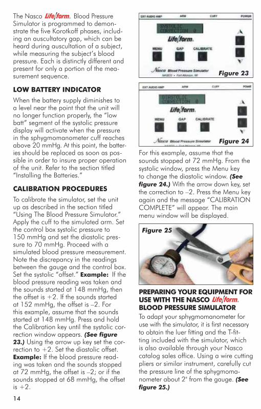
Figure 3
eyesThe eyes may be removed by creasing the skin at the outside of each eye and rolling the eye up. (See figure 3.)
geneRAL instRUCtion FoR CAReGERi™/KERi™ comes completely assembled and is simple to take apart if needed. Most cleaning can by done with a soft cloth and warm water. Avoid washing the painted areas on the mani-kin. Stubborn stains can be treated by using REN cleaner and a soft rag. Stains caused by makeup, ink, and newsprint are indelible and cannot be removed. Avoid contact with these substances. Do not apply cosmetics or betadine solution to the manikin.
oRAL hygieneToothbrushing should be preformed without water or any cleaning agents to avoid leaking into the head of the mani-kin, and to simplify cleanup. Denture removal is accomplished by grasping the dentures, pulling forward and then down (for the upper plate), or forward and then up (for the lower plate).
eye iRRigAtionBoth eyes may be irrigated using water only. To drain, tilt the head sideways and empty into a basin or onto an absorbent cloth. Cotton swabs should be used carefully and only on the outer ear.
eAR CAReBoth ears may be irrigated using water only. To drain, tilt the head sideways and empty into a basin or onto an absorbent cloth. Cotton swabs should be used carefully and only on the outer
BeD BAths AnD hAiR WAshingTo simplify cleanup, dry bed baths and shampoos are recommended to elimi-nate the chance of water entering the inside of the manikin. However, a soft cloth and water can be used for bath-ing exercises, and a mild shampoo and cool water can be used for hair wash-ing. Avoid scrubbing any painted areas of the manikin. To dry the wig, blot with a soft towel and air dry. Do not brush the hair when wet and never use a hair dryer or blow dryer on the wig.
mALe CAtheteRizAtion (not Available on Basic)
Note: To avoid the possibility of leakage, make sure you use the 16 French Foley catheter supplied with the simulator.
The male genital insert represents an uncircumcised adult male. To prepare for catheterization exercises, fill the 140 cc syringe (supplied) with water. Lubricate the end of the administration tube and insert through the urethra at least 7"-8". Be sure the catheter bag and fitting are attached to the urethra behind the genital insert. The Velcro® on the catheter bag should be secured to the Velcro® on the genital track. Depress the plunger of the syringe to fill the catheter bag. The catheter bag has a capacity of approximately 375 cc.
Figure 4
314
The Nasco Blood Pressure Simulator is programmed to demon-strate the five Korotkoff phases, includ-ing an auscultatory gap, which can be heard during auscultation of a subject, while measuring the subject’s blood pressure. Each is distinctly different and present for only a portion of the mea-surement sequence.
LoW BAtteRy inDiCAtoR
When the battery supply diminishes to a level near the point that the unit will no longer function properly, the “low batt” segment of the systolic pressure display will activate when the pressure in the sphygmomanometer cuff reaches above 20 mmHg. At this point, the batter-ies should be replaced as soon as pos-sible in order to insure proper operation of the unit. Refer to the section titled “Installing the Batteries.”
CALiBRAtion pRoCeDURes
To calibrate the simulator, set the unit up as described in the section titled “Using The Blood Pressure Simulator.” Apply the cuff to the simulated arm. Set the control box systolic pressure to 150 mmHg and set the diastolic pres-sure to 70 mmHg. Proceed with a simulated blood pressure measurement. Note the discrepancy in the readings between the gauge and the control box. Set the systolic “offset.” example: If the blood pressure reading was taken and the sounds started at 148 mmHg, then the offset is +2. If the sounds started at 152 mmHg, the offset is –2. For this example, assume that the sounds started at 148 mmHg. Press and hold the Calibration key until the systolic cor-rection window appears. (See figure 23.) Using the arrow up key set the cor-rection to +2. Set the diastolic offset. example: If the blood pressure read-ing was taken and the sounds stopped at 72 mmHg, the offset is –2; or if the sounds stopped at 68 mmHg, the offset is +2.
For this example, assume that the sounds stopped at 72 mmHg. From the systolic window, press the Menu key to change the diastolic window. (See figure 24.) With the arrow down key, set the correction to –2. Press the Menu key again and the message “CALIBRATION COMPLETE” will appear. The main menu window will be displayed.
pRepARing yoUR eqUipment FoR Use With the nAsCo BLooD pRessURe simULAtoRTo adapt your sphygmomanometer for use with the simulator, it is first necessary to obtain the luer fitting and the T-fit-ting included with the simulator, which is also available through your Nasco catalog sales office. Using a wire cutting pliers or similar instrument, carefully cut the pressure line of the sphygmoma-nometer about 2" from the gauge. (See figure 25.)
Figure 24
Figure 23
Figure 25
NP 081-07 Geri/Keri Manikins.ind5 5 9/13/07 7:52:30 AM
Enema Administration — FemaleEye IrrigationGastrostomy Care, Lavage, Gavage
(only on Complete, Advanced, and Auscultation)
Hair Care — Washing, CombingHearing Aid Removal and Insertion
TechniquesInjection Sites — 4 IntramuscularIntramuscular Injection Sites — Arms,
Thigh, and ButtockIV Arm Attachment (optional
on Basic, Complete, and Auscultation)
Oral HygieneOstomy Care — Ileostomy and
Colostomy, Lavage and Suctioning
Pap Smears and Douching Patient Positioning — Superior Range
of MotionPatient Transfer TechniquesProstate Exam — Stage B — MaleTracheostomy Care — Lavage and
SuctioningUrinary Catheterization — Female
and Male (Uncircumcised)
sUpeRioR RAnge oF motionGERi™/KERi™ manikins offer the most complete and realistic range of motion with no pinch points. This allows for correct patient positioning. The manikin’s articulation includes:trunk — rotation, hyperextensionshoulder — abduction, adduction,
rotation, hyperextensionelbow — extension, flexion, pronation,
supinationWrist — flexion, hyperextension, radial
flexion, ulnar flexionFingers — abduction, adduction,
flexion (soft, lifelike material)neck — rotation, hyperextension,
lateral flexionhip — abduction, adduction, rotation,
hyperextensionKnee — extension, flexionAnkle — eversion, inversion, dorsiflexion,
plantarflexiontoes — abduction, adduction, flexion
(soft, lifelike material)
ARmsArms can be removed by bending the elbows backward approximately 90˚ to align the keyholes at the shoulders, pull outward away from shoulder of the manikin. Reverse this procedure to reas-semble. (See figure 1.)
LegsThe legs detach from the body at the hips by bending the legs backward approximately 150˚ so that the feet are near the shoulders and the keyholes are aligned. The legs can now be pulled outward away from the body. Reverse these procedures to reassemble. (See figure 2.)
heADThe head may be removed by rotating it 180˚ backwards to align with the key-holes, and pull up. Reverse this proce-dure to reassemble.JointsAll other joints may be disassembled with a flat-head screwdriver. Hold the opposite end of the connector pin to prevent unproductive rotation.
Figure 1
Figure 2
152
Take the T-fitting and insert it between the two ends of tubing that were previ-ously cut. (See figure 26.) Assemble the portion of pressure line tubing over the remaining barbed end on the T-fitting. (See figure 27.)
Lastly, take the loose end of the tubing and push the female luer fitting into it. (See figure 28.) Attach the female luer fitting to the fitting marked CUFF at the top of the unit. Once all of the necessary connections have been properly made, go to the section titled “Calibration Procedures” and calibrate the unit. When the calibration proce-dures have been completed, the simula-tor is ready for use.
sUppLies/RepLACement pARts FoR BLooD pRessURe simULAtoRLF01096U Electronic Control Unit with SphygmomanometersB20146U Blood Pressure Speaker System
Figure 26
Figure 27
Figure 28
the AUsCULtAtion simULAtoR
The Auscultation Manikin duplicates heart and lung conditions selected by the instructor by wireless remote control. The student should palpate to identify the correct auscultation sites and will hear different heart and lung sounds as the SmartScope™ is moved from site to site.
The simulator has six heart sites, seven lung sound sites on the anterior surface with 10 locations on the posterior sur-face and midaxillary sites. The remote control can select from 12 different heart conditions, as well as 16 lung conditions. The instructor can select any condition easily so the student can compare sounds and make a diagnosis.
The remote control does not have to be pointed directly at the manikin or stethoscope to operate. One remote control will operate multiple sets of SmartScopes™ and manikins simultane-ously. Great for group instruction. The range of the remote control is up to 100 feet.
geneRAL instRUCtions FoR Use
To begin using the Auscultation Trainer, press the red power button. This turns on the remote control and sends a sig-nal to activate the stethoscope as well. After the unit is activated, the display will be in the “status” mode, displaying the current menu settings for the heart and lung conditions.
To select a new condition, press either the heart or lung button. This will put the display into the menu mode. The user can select a condition by either using the number buttons, or by viewing the conditions in sequence using the scroll button. After the condition is selected press the enter button to activate.
NP 081-07 Geri/Keri Manikins.ind4 4 9/13/07 7:52:27 AM
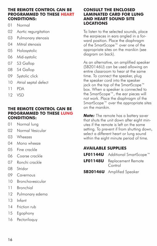
Basic GERi™ LF04040UBasic KERi™ LF04021UList oF Components
Male genitaliaFemale genitaliaWigDenturesHearing Aid12 cc syringeREN cleanerLubricant spraySerial number — located under the
skin at the back of the neck
Advanced GERi™ LF04030UAdvanced KERi™ LF04022UList oF Components
Male genitaliaFemale genitaliaWigDenturesHearing Aid12 cc syringeREN cleanerLubricant sprayFluid drainage basinCatheter bag with fitting and pres-
sure sleeveRight iV training ArmLeft Blood pressure training ArmSerial number — located under the
skin at the back of the neck
VisUAL inspeCtion FeAtUResCancerous Mole ComparisonDecubitus Sacral Ulcer — Stage 1Dilated Pupil ComparisonSkin Wrinkles and FoldsElderly Appearance (GERi™ only)
1
Complete GERi™ LF04001UComplete KERi™ LF04020UList oF Components
Male genitaliaFemale genitaliaWigDenturesHearing Aid12 cc syringeREN cleanerLubricant sprayFluid drainage basinCatheter bag with fitting and pres-
sure sleeveSerial number — located under the
skin at the back of the neck
Auscultation GERi™ LF04003UAuscultation KERi™ LF04024UList oF Components
Male genitaliaFemale genitaliaWigDenturesHearing Aid12 cc syringeREN cleanerLubricant sprayFluid drainage basinCatheter bag with fitting and pres-
sure sleevesmart scope™ with single and dual
headpiecesRemote Control with LCD
displaytwo “AA” and two “AAA” batteriesSerial number — located under the
skin at the back of the neck
pAtient CARe simULAtionBandaging Finger and Toe — Flexible
and Individually MoldedBandaging and Wound DressingBed BathsBlood Pressure Arm Attachment
(optional on Basic, Complete, and Auscultation)
Clothing ChangesDenture Removal — Upper and
Lower
the Remote ContRoL CAn Be pRogRAmmeD to these heARt ConDitions:
01 Normal
02 Aortic regurgitation
03 Pulmonary stenosis
04 Mitral stenosis
05 Holosystolic
06 Mid-systolic
07 S3 Gallop
08 S4 Gallop
09 Systolic click
10 Atrial septal defect
11 PDA
12 VSD
the Remote ContRoL CAn Be pRogRAmmeD to these LUng ConDitions:
01 Normal lung
02 Normal Vesicular
03 Wheezes
04 Mono wheeze
05 Fine crackle
06 Coarse crackle
07 Ronchi crackle
08 Stridor
09 Cavernous
10 Bronchovesicular
11 Bronchial
12 Pulmonary edema
13 Infant
14 Friction rub
15 Egophony
16 Pectoriloquy
ConsULt the enCLoseD LAminAteD CARD FoR LUng AnD heARt soUnD site LoCAtions
To listen to the selected sounds, place the earpieces in ears angled in a for-ward position. Place the diaphragm of the SmartScope™ over one of the appropriate sites on the manikin (see diagram on back).
As an alternative, an amplified speaker (SB20146U) can be used allowing an entire classroom to hear at the same time. To connect the speaker, plug the speaker cord into the speaker jack on the top of the SmartScope™ box. When a speaker is connected to the SmartScope™, the ear pieces will not work. Place the diaphragm of the SmartScope™ over the appropriate sites on the manikin.
Note: The remote has a battery saver that shuts the unit down after eight min-utes if the remote is left on the same setting. To prevent if from shutting down, select a different heart or lung sound within the eight minute period of time.
AVAiLABLe sUppLies
LF01144U Additional SmartScope™
LF01148U Replacement Remote Control
sB20146U Amplified Speaker
16
NP 081-07 Geri/Keri Manikins.ind3 3 9/13/07 7:52:22 AM
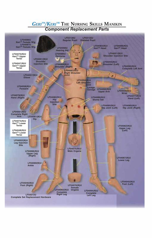
Congratulations for choosing a GERi™/KERi™ nursing skills manikin. This realistic, fully functional, lightweight nursing manikin comes with a superior range of motion and allows you to simulate over 35 nurs-ing and medical procedures. The quality and simple design makes this manikin easy to use and care for while teaching your students basic patient care techniques, so please familiarize yourself with this manual before using the manikin for student training. three-year warranty.
In the Basic GERi™/KERi™ manikins the internal fluid reservoirs have been eliminated for greater economy. Ostomy care, oral and nasal lavage, gavage, and suctioning procedures cannot be per-formed but can be simulated. Urinary catheterization and enema administration cannot be simulated.
Advanced GERi™
LF04051(N)UShoulder Injection Site
LF04056(N)UUpper Arm
LF04089(N)UStoma Set
LF04059(N)UWrist
LF04077(N)UHand (Left)
LF04062(N)UUpper Leg
(Left)
LF04067(N)ULower Leg
LF04045(N)UFoot (Left)LF04076(N)U
Female Organs
LF04072UComplete Set Replacement Hardware
LF04046(N)UFoot (Right)
LF04069(N)UAnkle
LF04066(N)UUpper Leg
(Right)
LF04052(N)ULeg Injection
Site
LF04078(N)UHand (Right)
LF04058(N)UForearm
LF04057(N)UElbow
LF04051(N)UShoulder
Injection Site
LF04085UDentures
LF04086UKeriTM Female Wig
LF04087UGeriTM Female Wig
LF04061(N)UHip
LF04082(N)UHip
Injection Site
LF04075(N)UMale Organs
LF04060(N)UHip Joint (Left)
LF04065(N)UHip Joint (Right)
LF04055(N)UShoulder (Left)
LF04070(N)UKeriTM Upper
Torso
LF04047(N)UGeriTM Upper
Torso
LF04083(N)UKeriTM Head
LF04088(N)UGeriTM Head
LF04073(N)UKeriTM Lower
Torso
LF04048(N)UGeriTM Lower
Torso
LF04063(N)URight Shoulder Joint
LF04054(N)ULeft Shoulder
Joint
LF04064(N)UShoulder (Right) LF04092(N)U
Complete Left Arm
LF03136URegular Pupil
LF03135UDialated Pupil
LF04090UHearing Aid
LF04093(N)UComplete Right Leg
Geri™/Keri™ The NursiNg skills MaNikiNComponent Replacement Parts
LF04091(N)UComplete Right
Arm
LF04094(N)UComplete Left Leg
Lavage,Gavage
NP 081-07 Geri/Keri Manikins.ind2 2 9/13/07 7:52:22 AM

GERi™/KERi™ the nURsing sKiLL mAniKins
the ideal manikin for all oBRA required training!
GERi™– LF04040U, LF04001U, LF04030U, LF04003UKERi™– LF04021U, LF04020U, LF04022U, LF04023U
instRUCtion mAnUAL
products by nascoCOPYRIGHT © NASCO 2007 PRINTED IN U.S.A. NP 081-07
other Available simulatorsLF00698U Adult Injectable Arm (White) LF00856U Female CatheterizationLF00885U Male Catheterization LF00901U Prostate Examination LF00906U Ostomy Care LF00929U Surgical Bandaging LF00957U Enema Administration LF00958U Pediatric Injectable Arm LF00961U Intramuscular Injection LF00984U Breast Examination LF00995U Arterial Puncture Arm LF00997U Adult Injectable Arm (Black) LF00999U Pediatric Injectable Head LF01008U Intradermal Injection Arm LF01012U Heart Catheterization (TPN) LF01019U Ear Examination LF01027U Peritoneal Dialysis LF01028U Suture Practice Arm LF01034U Suture Practice LegLF01036U Spinal Injection LF01037U Hemodialysis Arm LF01038U Episiotomy SuturingLF01042U Suture KitLF01062U Pelvic, Normal & Abnormal LF01063U Stump Bandaging, Upper LF01064U Stump Bandaging, Lower LF01069U Cervical Effacement LF01070U Birthing Station LF01082U Cricothyrotomy LF01083U Tracheostomy Care LF01084U Sigmoidoscopic
Examination LF01087U Central Venous Cannulation LF01095U Blood Pressure Arm LF01108U Infant Intraosseous Infusion
Simulator LF01121U Advanced IV Arm LF01131U Venipuncture and Injection ArmLF01139U Advanced IV Hand LF01142U Auscultation TrainerLF01143U Testicular ExamLF01152U Male & Female CatheterLF01155U CPR Dog
LF01162U Venatech IV Trainer LF01174U NG Tube & Track SkillsLF01184U Venatech IM & Sub Q LF01193U Special Needs BabyLF03000U CPARLENE® Series LF03601U Adult Airway Management Trainer with Stand LF03602U Adult Airway Management on Manikin LF03609U Child Airway Management Trainer with StandLF03616U Child CRiSis™ ManikinLF03617U Deluxe Child CRiSis™ Manikin with Arrhythmia TutorLF03620U PALS Update KitLF03623U Infant Airway Management Trainer with standLF03632U Child Intraosseous Infusion/ Femoral Access Leg on a StandLF03633U Child Airway Management Trainer with TorsoLF03693U Basic Buddy CPR ManikinLF03699U “Airway Larry” Airway Management TrainerLF03709U Infant CRiSis™ManikinLF03720U Baby Buddy Infant CPR ManikinLF03750U Fat Old FredLF03760U Airway Management/Cricoid Pressure TrainerLF03770U Chest TubeLF03953U CRiSis™ Manikin, completeLF03955U Deluxe CRiSis™ ManikinLF03965U Deluxe “Plus” CRiSis™ ManikinLF04200U Adult Sternal Intraosseous InfusionLF06001U CPR Prompt™ Adult/Child ManikinLF06012U CPR Prompt™ Infant ManikinLF06200U CPR Prompt™ Keychain Rescue AidLF06204U CPR Prompt™ Rescue and Practice Aid
901 Janesville Avenue, P.O. Box 901Fort Atkinson, Wisconsin 53538-0901
1-800-558-9595www.eNasco.com • E-mail: [email protected]
Fort Atkinson
the nURsing
GERi™ KERi™
NP 081-07 Geri/Keri Manikins.ind1 1 9/13/07 7:52:07 AM