geosynthetically confined soils - north dakota local ... riprap under structure complete both...
TRANSCRIPT

Geosynthetically Confined Soils
(FABRIC) and other Technologies Brian Keierleber P.E.
Regional Local Roads Conference
October 23, 2013

What we are faced with

Many of our bridges are old

Our System Cannot meet Today’s
Demands

We Have NOT kept up with
Modern Agriculture
Loaded
Semi
POSTING FOR
SEMI

Postings Do Not Work unless I am
there.

The sign says 3 ton Gross

WE KNOW WHAT THE RESULTS
WILL BE!

10/09/10 & 10/14/10 & 10/10/18/10

Without Enforcement and
legislation our problems will grow
• April 4, 2011
• Reports of 2-770 gal
manure tanks
crossing 22 ton bridge
loaded
• April 7, 2011 reports
of a semi crossing a 3
ton bridge

DUCT TAPE CANNOT FIX
EVERYTHING

We MUST FIND NEW WAYS

UTILIZE NEW TECHNOLOGIES

ADAPT TO LOCAL CONSTRUCTION
METHODS

START AT THE BASE

Start With 2 LAYERS 1 As A
CURTAIN WALL

COMPACT 8” LIFTS
NOTE THE PILING WERE VIBRATED
IN

COMPACT

LEVEL AND COMPACT AGAIN

COMPLETE ONE SIDE

EXCAVATE FOR CURTAIN WALL

RIPRAP

TIE RIPRAP UNDER STRUCTURE
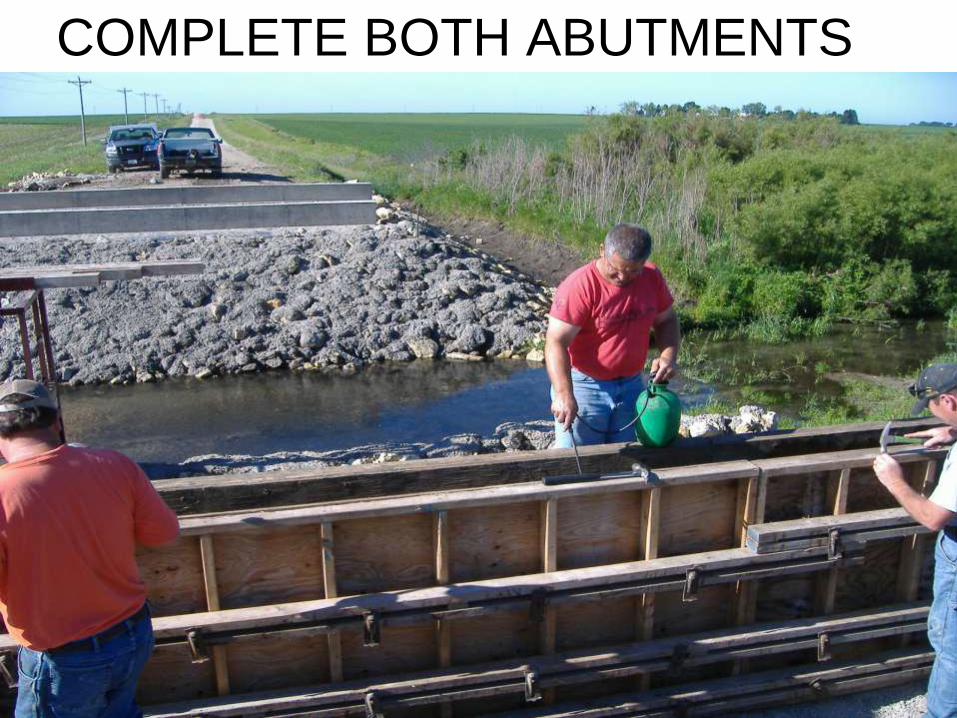
COMPLETE BOTH ABUTMENTS

PLACE CURTAIN WALL PAST
ABUTMENT

BUILD WINGS

SET SUPERSTRUCTURE

COMPLETE SUPERSTRUCTURE

COMPLETE BRIDGE

EVALUATE the PROCESS

250 St Bridge

LETS LEARN MORE

Various options – Design for the Location
73 ft long Rail Road Flat Car Bridge
Spread Footing Foundation
Rock Fill for Scour/ErosionProtection
Reinforcement Length
Flexible wrapped geosyntheticfacing
Expansion Joint
Flexible Facing – Wrapped Geosynthetics, Concrete Blocks,
Gabions, or Timber, etc.
Hoods Bridge, Buchanan
County
Boone Bridge, Boone TR-568, IHRB Project
Rigid Facing – Sheet pile walls, Pre-Cast or Cast-In Place Concrete
Walls

Iowa State University
• PIEZOMETERS
• To Monitor water pressure
• INCLINOMETERS • To monitor ground movement during excavation, sheet piling,
fill compaction, and after bridge loading
• EARTH PRESSURE CELLS • To monitor total stresses under the footing and at the ground at
different elevations

Subsurface Conditions
3.8
1 f
t
3 f
t
4.5
ft
28 in
8 in
7.4 ft
Lift 1
Lift 2
Lift 3
Lift 4
Lift 5
Lift 6
Semi-conductor
EPC's
Vibrating wire
EPC's
Semi-conductor
EPC at center line
Vibrating wire EPC's at
center, left, and right
under the footing
Reinforced
Concrete
Footing
Front-Face of the
Concrete Abutment
Wall
250th Street West
Previous Road
Elevation
1.6
ft
Final Road Elevation
68.5 ft long Rail Road Flat Car
B-1(Inclinometer
bottom at 12.5 ft below this surface)
6.7 in thick Gravel
GravelBackfill11 ft
Waterlevel measured
during construction
Waterlevel
measured during
Summer 2010
B-3(Piezometer)
10
in
6.8
ft
ST
ST
ST
PA
ST
B
B
B
Dark Brownto Dark Gray Brown Sandy
Clay
Rock/Concrete?
Brown ClayeySand
Brown GraySandy LeanClay (Glacial
Till)
ST - Shelby Tube SamplePA - Power AugerB - Bulk Sample
2.4 ft
6.7 in
Steel BlocksNeoprene Pad

Installation of Inclinometer

NE-SW Direction
Cumulative Deflection (in)
-0.4 -0.2 0.0 0.2 0.4
Y D
ata
0
2
4
6
8
10
12
14
SE-NW Direction
Cumulative Deflection (in)
-0.4 -0.2 0.0 0.2 0.40
2
4
6
8
10
12
14
After Excavation
After Sheet Piling
After Fill Compaction
SW NE NW SE
Towards Excavation
Away from Excavation
Towards Excavation
Away from Excavation
NE SE
NW SW
Boring 1
Bottom of Excavation
Inclinometer about 2 ft away from excavation

LOAD CELLS

LOADCELLS IN THE ABUTMENT

WIRES

Lift 6
Lift 5
Lift 4 Lift 3
Lift 2 Lift 1

Light Weight Deflectometer (LWD) Tests on each lift to measure Modulus
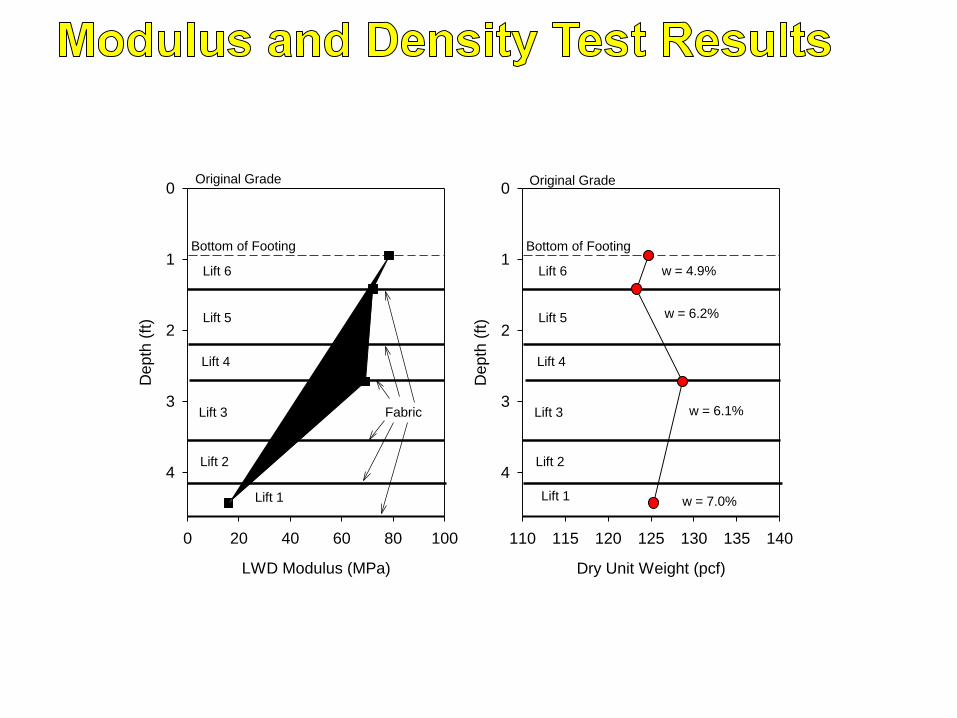
LWD Modulus (MPa)
0 20 40 60 80 100
Depth
(ft
)
0
1
2
3
4
Bottom of Footing
Dry Unit Weight (pcf)
110 115 120 125 130 135 140
Dep
th (
ft)
0
1
2
3
4
Bottom of Footing
w = 4.9%
w = 6.2%
w = 6.1%
w = 7.0%
Fabric
Lift 1
Lift 2
Lift 3
Lift 4
Lift 5
Lift 6
Lift 1
Lift 2
Lift 3
Lift 4
Lift 5
Lift 6
Original Grade Original Grade

COMPLETED ABUTMENTS

SETTING SUPERSTRUCTURE

TESTING

ON Site Data Logger with Wireless
Modem

HIGH SPEED TESTING

My Knowledge

My Resources

YOUR RESOURCES

• Iowa Department of Transportation
• Buchanan County Staff
– Randy Andrews, Phil Fangman, Jeff White, Chuck
Kivell, Dick Lehs, Alex Davis, Tom Reidy, Andy
Monaghan, Ron Crawford, Rick Wendling, Jerry
Slattery, Brian Donnelly, and Ned Johnson
• Iowa State University Staff
• Pavana Venaposa Heath Gieselman, David White,
Wayne Klaiber
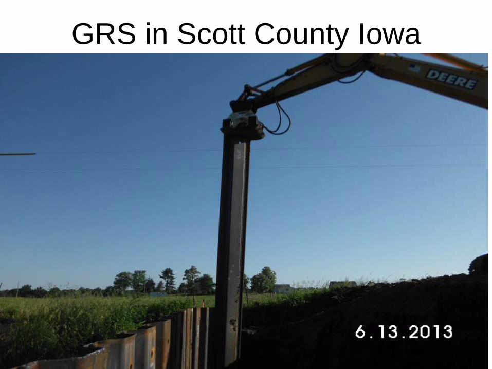
GRS in Scott County Iowa

Scott Co. placing the lifts
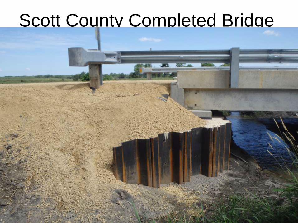
Scott County Completed Bridge
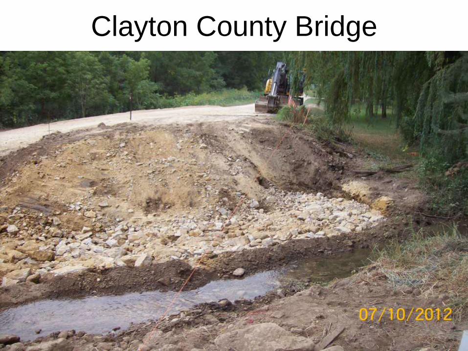
Clayton County Bridge
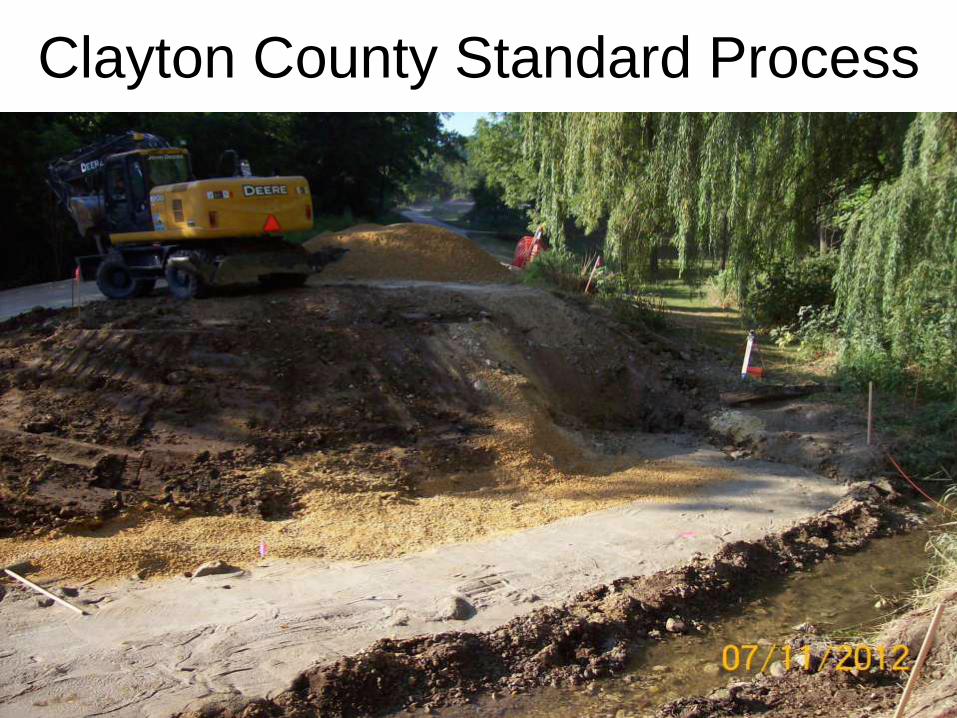
Clayton County Standard Process

8” lifts using block

Steel Beam in Slab Design

Clayton County Construction in
Progress
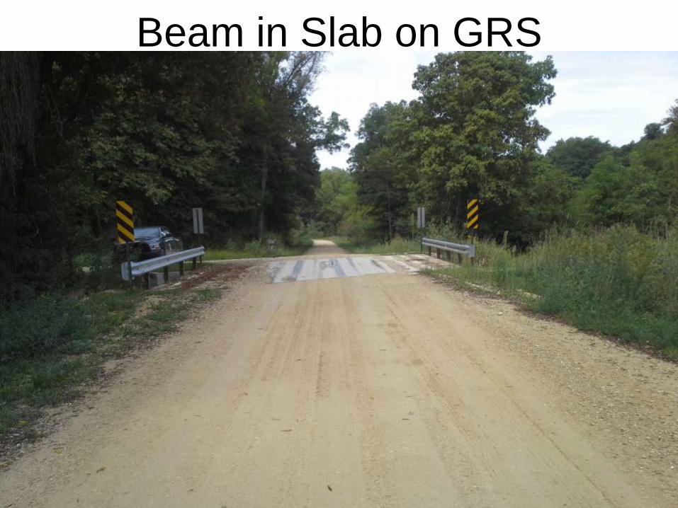
Beam in Slab on GRS

Clayton Co. Cherry Valley Rd
Bridge completed
• Cherry Valley Rd Bridge.

Launching was the concept


Plans are through Iowa State and
the IDOT


Gerstenbergers Bridge

Not all things work SAFETY rules

Constantly Improve The Methods

Compacted Concrete on GRS

Completed Abutment face on a 1:1
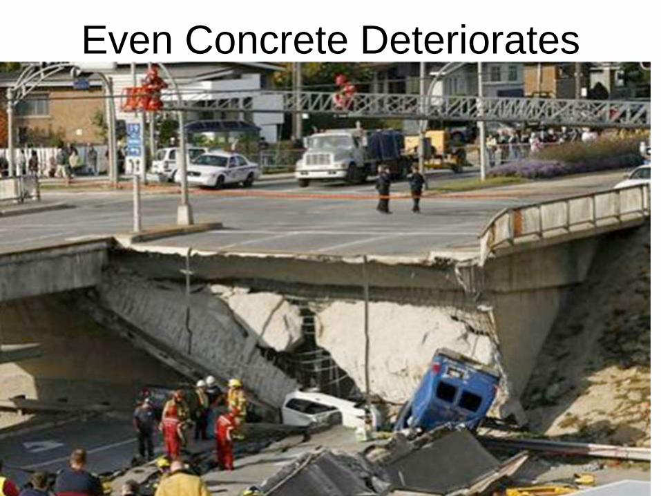
Even Concrete Deteriorates

New Technology through organizations like
the Short Span Steel Bridge Alliance
• National Association of County Engineers is a founding member
• Provides counties with Innovative and cost-effective solutions for short span
steel bridges.
• www.ShortSpanSteelBridges.org
• Free web-based design tool available for short span steel bridges
• eSPAN140 (www.eSPAN140.com)
• Used to design a steel bridge in Buchanan County, Iowa

New Technologies such as e-span
140 will impact how we do business

Case Study Bridges: Side-by-
Side Comparison
Audrain County, MO Bridge 411
Built 2012
Steel 4 Girders
47.5 ft Span, 24 ft Roadway Width
2 ft Structural Depth
No Skew
Audrain County, MO Bridge 336
Built 2012
Precast 6 Hollowcore Slab Girders
50.5 ft Span, 24 ft Roadway Width
2 ft Structural Depth
20o Skew
Steel Concrete

Total Bridge Costs
Material = $41,764
Labor = $24,125
Equipment = $21,521
GuardRail = $ 7,895
Rock = $ 8,302
Engineering = $ 8,246
TOTAL = $111,853
Total Bridge Costs
Material = $67,450
Labor = $26,110
Equipment = $24,966
GuardRail = $ 6,603
Rock = $ 7,571
Engineering = $21,335
TOTAL = $154,035
Case Study Bridges: Side-by-Side Comparison
Steel Concrete

Folded Plate Steel Bridge Concepts
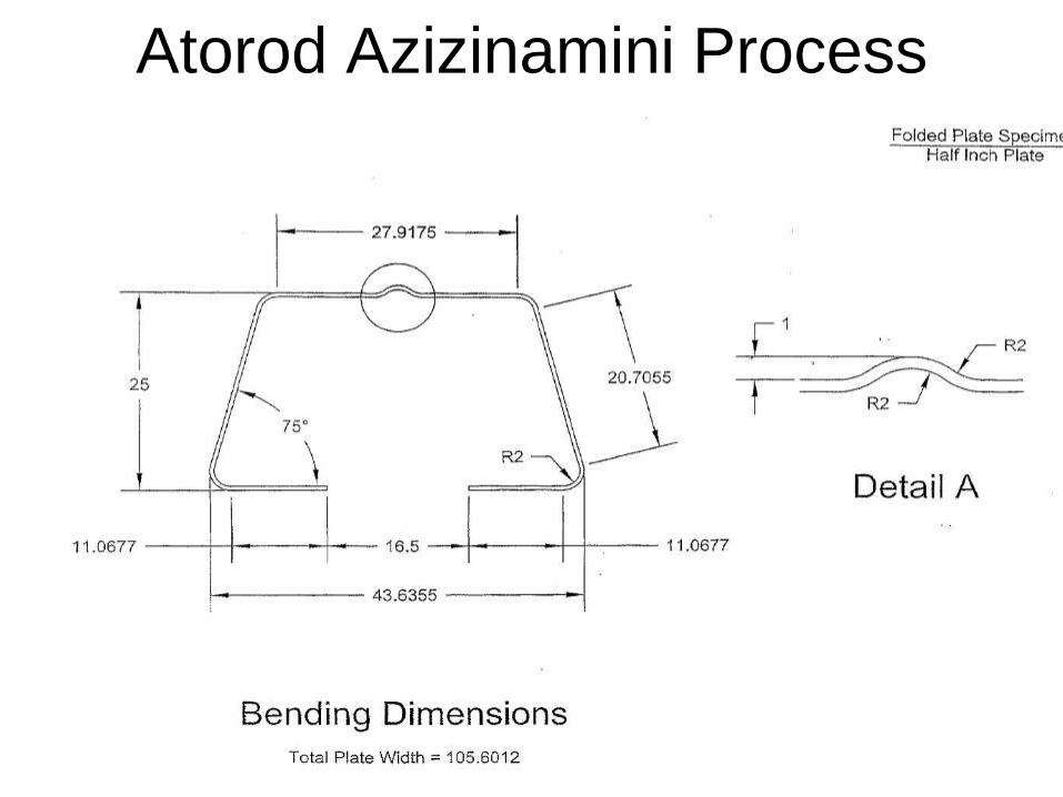
Atorod Azizinamini Process

The

Initial tests are very promising


The Bottom Line is the COST


ULTRA HIGH PERFORMANCE
CONCRETE

UHPC Design Data
• Modulus of elasticity final = 7,500 ksi
• Compressive strength at release = 14.5 ksi
• Compressive strength final = 21.5 ksi
• Tensile strength ~ 1.20 ksi
– We actually broke cylinders at 32 ksi.

Initial Cost
Coating System $/ft2 Total
Inorganic Zinc $1.35 $40,410
Hot-Dip Galvanizing $1.60 48,000
Inorganic Zinc/Epoxy $2.16 $64,800
Acrylic WB Primer/ Acrylic WB
Intermediate/ Acrylic WB Topcoat $2.55 $76,620
Inorganic Zinc Primer/ Epoxy/
Polyurethane Topcoat $3.17 $94,950
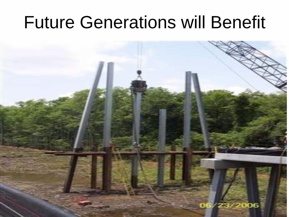
Future Generations will Benefit

Internal Curing Concrete

Completed Roundabout

Pavements from BIO-OILS

Be Creative

ANY QUESTIONS?

THANK YOU