g1314b /g1314c (sl) - agilent analytical instrumentsaimanalytical.com/manuals/1200 vwd.pdf · a...
TRANSCRIPT
Agilent 1200 Series Variable Wavelength Detector
G1314B /G1314C (SL)
User Manual
A

2 1200 Series Variable Wavelength Detector User Manual
Notices© Agilent Technologies, Inc. 2006
No part of this manual may be reproduced in any form or by any means (including electronic storage and retrieval or translation into a foreign language) without prior agreement and written consent from Agilent Technologies, Inc. as governed by United States and international copyright laws.
Manual Part NumberG1314-90010
Edition 02/06
Printed in Germany
Agilent TechnologiesHewlett-Packard-Strasse 8 76337 Waldbronn, Germany
Manual StructureThe User Manual G1314-90010 (English) and its localized versions contain a subset of the Service Manual and is shipped with the detector in printed matter.
Latest versions of the manuals can be obtained from the Agilent web.
The Service Manual G1314-90110 (English) contains the complete information about the Agilent 1200 Series Variable Wavelength Detector. It is available as Adobe Reader file (PDF) only.
WarrantyThe material contained in this docu-ment is provided “as is,” and is sub-ject to being changed, without notice, in future editions. Further, to the max-imum extent permitted by applicable law, Agilent disclaims all warranties, either express or implied, with regard to this manual and any information contained herein, including but not limited to the implied warranties of merchantability and fitness for a par-ticular purpose. Agilent shall not be liable for errors or for incidental or consequential damages in connec-tion with the furnishing, use, or per-formance of this document or of any information contained herein. Should Agilent and the user have a separate written agreement with warranty terms covering the material in this document that conflict with these terms, the warranty terms in the sep-arate agreement shall control.
Technology Licenses The hardware and/or software described in this document are furnished under a license and may be used or copied only in accordance with the terms of such license.
Restricted Rights LegendSoftware and technical data rights granted to federal government customers include only those rights customarily provided to end user Customers of Software. Agilent provides this customary commercial license in Software and technical data pursuant to FAR 12.211 (Technical Data) and FAR 12.212 (Computer Software) and, for Department of Defense purchases, DFARS 252.227-7015 (Technical Data - Commercial Items) and DFARS 227.7202-3 (Rights in Commercial Computer Software or Computer Software Documentation). If a federal government or other public sector Customer has a need for
rights not conveyed under these terms, it must negotiate with Agilent to establish acceptable terms in a written agreement executed by all relevant parties.
Safety Notices
CAUTION
A CAUTION notice denotes a haz-ard. It calls attention to an operat-ing procedure, practice, or the like that, if not correctly performed or adhered to, could result in damage to the product or loss of important data. Do not proceed beyond a CAUTION notice until the indicated conditions are fully understood and met.
WARNING
A WARNING notice denotes a hazard. It calls attention to an operating procedure, practice, or the like that, if not correctly per-formed or adhered to, could result in personal injury or death. Do not proceed beyond a WARNING notice until the indicated condi-tions are fully understood and met.

In This Manual…This manual covers the Agilent 1200 Series Variable Wavelength Detectors
1 Introduction to the Variable Wavelength Detector
This chapter gives an introduction to the detector, instrument overview and internal connectors.
2 Site Requirements and Specifications
This chapter gives information on environmental requirements, physical and performance specifications.
3 Installing the Detector
This chapter describes the installation of the detector.
4 Using the Detector
This chapter provides information on how to set up the detector for an analysis and explains the basic settings.
5 How to optimize the detector
This chapter gives hints on how to select the detector parameters and the flow cell.
7 Maintenance and Repair
This chapter provides general information on maintenance and repair of the detector.
8 Maintenance
This chapter describes the maintenance of the detector.
G1314B Agilent 1200 Series VWD
G1314C Agilent 1200 Series VWD-SL
1200 Series Variable Wavelength Detector User Manual 3

9 Parts and Materials for Maintenance
This chapter provides information on parts for maintenance.
A Appendix
This chapter provides addition information on safety, legal and web.
4 1200 Series Variable Wavelength Detector User Manual

Contents
1 Introduction to the Variable Wavelength Detector
Introduction to the Detector 10
Optical System Overview 11
Electrical Connections 15
Instrument Layout 17
Early Maintenance Feedback (EMF) 18
EMF Counter 18Using the EMF Counters 18
2 Site Requirements and Specifications
Site Requirements 22
Physical Specifications 24
Performance Specifications 25
3 Installing the Detector
Unpacking the Detector 28
Optimizing the Stack Configuration 30
Installing the Detector 33
Flow Connections to the Detector 36
4 Using the Detector
Setting up an Analysis 40
Before Using the System 40Requirements and Conditions 42
1200 Series Variable Wavelength Detector User Manual 5

Optimization of the System 44Preparing the HPLC System 45Running the Sample and Verifying the Results 54
Special Settings of the Detector 55
Control Settings 55Online Spectra 56Scanning with the VWD 57Analog Output Settings 59Special Setpoints 60Peakwidth Settings 61Optimizing the Detector 63
5 How to optimize the detector
Optimizing the Detector Performance 66
Match the Flow Cell to the Column 66Set the Detector Parameters 69
6 Troubleshooting and Diagnostics
Overview of the Detector’s Indicators and Test Functions 72
Status Indicators 73
Power Supply Indicator 73Detector Status Indicator 74
User Interfaces 75
Agilent LC Diagnostic Software 76
7 Maintenance and Repair
Introduction to Maintenance and Repair 78
Simple Repairs - Maintenance 78Exchanging Internal Parts - Repair 78
Warnings and Cautions 79
6 1200 Series Variable Wavelength Detector User Manual
Cleaning the Detector 80
Using the ESD Strap 81
8 Maintenance
Overview of Maintenance 84
Exchanging a Lamp 85
Exchanging a Flow Cell 87
Repairing the Flow Cells 90
Using the Cuvette Holder 94
Correcting Leaks 97
Replacing Leak Handling System Parts 98
Replacing the Interface Board 99
Replacing the Detector’s Firmware 100
Tests & Calibrations 101
Intensity Test 102
Wavelength Verification/Calibration 104
Holmium Oxide Test 105
9 Parts and Materials for Maintenance
Overview of Maintenance Parts 110
Standard Flow Cell 111
Micro Flow Cell 112
Semi-micro Flow Cell 113
High Pressure Flow Cell 115
Cuvette Holder 116
Leak Parts 117
1200 Series Variable Wavelength Detector User Manual 7

Accessory Kit 118
A Appendix
General Safety Information 120
Lithium Batteries Information 123
Radio Interference 124
Sound Emission 125
UV-Radiation 126
Solvent Information 127
Declaration of Conformity for HOX2 Filter 129
Agilent Technologies on Internet 130
Index
8 1200 Series Variable Wavelength Detector User Manual
Agilent 1200 Series Variable Wavelength DetectorUser Manual
1Introduction to the Variable Wavelength Detector
Introduction to the Detector 10
Optical System Overview 11
Flow Cell 12
Electrical Connections 15
Instrument Layout 17
Early Maintenance Feedback (EMF) 18
This chapter gives an introduction to the detector, instrument overview and internal connectors.
9Agilent Technologies

1 Introduction to the Variable Wavelength Detector
Introduction to the Detector
The Agilent 1200 Series variable wavelength detector is designed for highest optical performance, GLP compliance and easy maintenance with:
• higher data rate (27/55Hz) for fast-HPLC with G1314C VWD-SL, see “Set the Detector Parameters" on page 69,
• deuterium lamp for highest intensity and lowest detection limit over a wavelength range of 190 to 600 nm,
• optional flow-cell cartridges (standard 10 mm 14 µl, high pressure 10 mm 14 µl, micro 5 mm 1 µl, semi-micro 6 mm 5 µl) are available and can be used depending on the application needs,
• easy front access to lamp and flow cell for fast replacement, and
• built-in holmium oxide filter for fast wavelength accuracy verification.
For specifications “Performance Specifications" on page 25.
Two version of the Agilent 1200 Series variable wavelength detector are available:
G1314B VWD 1200 Series Variable Wavelength Detectorstandard version
G1314C VWD-SL 1200 Series Variable Wavelength Detector SLhigh data rates for fast HPLC
NOTE The G1314C VWD-SL can be operated with a G1323B Control Module just in standard mode as G1314B - no higher data rate selection is available.
10 1200 Series Variable Wavelength Detector User Manual
Introduction to the Variable Wavelength Detector 1
Optical System Overview
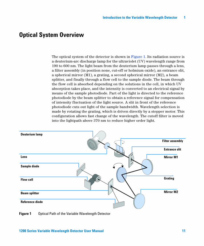
The optical system of the detector is shown in Figure 1. Its radiation source is a deuterium-arc discharge lamp for the ultraviolet (UV) wavelength range from 190 to 600 nm. The light beam from the deuterium lamp passes through a lens, a filter assembly (in position none, cut-off or holmium oxide), an entrance slit, a spherical mirror (M1), a grating, a second spherical mirror (M2), a beam splitter, and finally through a flow cell to the sample diode. The beam through the flow cell is absorbed depending on the solutions in the cell, in which UV absorption takes place, and the intensity is converted to an electrical signal by means of the sample photodiode. Part of the light is directed to the reference photodiode by the beam splitter to obtain a reference signal for compensation of intensity fluctuation of the light source. A slit in front of the reference photodiode cuts out light of the sample bandwidth. Wavelength selection is made by rotating the grating, which is driven directly by a stepper motor. This configuration allows fast change of the wavelength. The cutoff filter is moved into the lightpath above 370 nm to reduce higher order light.
Figure 1 Optical Path of the Variable Wavelength Detector
Deuterium lamp
Filter assembly
Lens
Entrance slit
Mirror M1
Mirror M2
Grating
Reference diode
Sample diode
Flow cell
Beam splitter
1200 Series Variable Wavelength Detector User Manual 11
1 Introduction to the Variable Wavelength Detector
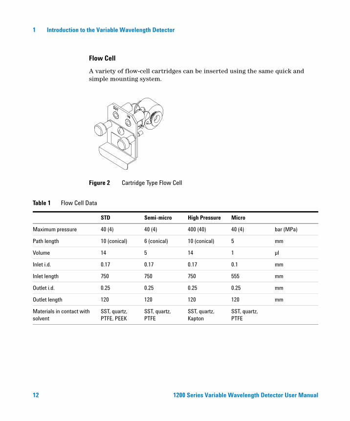
Flow Cell
A variety of flow-cell cartridges can be inserted using the same quick and simple mounting system.
Figure 2 Cartridge Type Flow Cell
Table 1 Flow Cell Data
STD Semi-micro High Pressure Micro
Maximum pressure 40 (4) 40 (4) 400 (40) 40 (4) bar (MPa)
Path length 10 (conical) 6 (conical) 10 (conical) 5 mm
Volume 14 5 14 1 µl
Inlet i.d. 0.17 0.17 0.17 0.1 mm
Inlet length 750 750 750 555 mm
Outlet i.d. 0.25 0.25 0.25 0.25 mm
Outlet length 120 120 120 120 mm
Materials in contact with solvent
SST, quartz, PTFE, PEEK
SST, quartz, PTFE
SST, quartz, Kapton
SST, quartz, PTFE
12 1200 Series Variable Wavelength Detector User Manual

Introduction to the Variable Wavelength Detector 1
Lamp
The light source for the UV wavelength range is a deuterium lamp. As a result of plasma discharge in a low pressure deuterium gas, the lamp emits light over the 190 to 600 nm wavelength range.
Source Lens Assembly
The source lens receives the light from the deuterium lamp and focuses it onto the entrance slit.
Entrance Slit Assembly
The entrance slit assembly has an exchangeable slit. The standard one has a 1-mm slit. For replacement and calibration purposes to optimize the alignment, a slit with a hole is needed.
Filter Assembly
The filter assembly is electromechanically actuated. During wavelength calibrations it moves into the light path.
The filter assembly has two filters installed and is processor-controlled.
A photo sensor determines the correct position.
OPEN nothing in light path
CUTOFF cut off filter in light path at λ > 370 nm
HOLMIUM holmium oxide filter for wavelength check.
Figure 3 Filter Assembly
Cutoff filter Holmium oxide filter with cutoff filter
1200 Series Variable Wavelength Detector User Manual 13
1 Introduction to the Variable Wavelength Detector
Mirror Assemblies M1 and M2
The instrument contains two spherical mirrors (M1 and M2). The beam adjustable is vertically and horizontally. Both mirrors are identical.
Grating Assembly
The grating separates the light beam into all its component wavelengths and reflects the light onto mirror #2.
Beam Splitter Assembly
The beam splitter splits the light beam. One part goes directly to the sample diode. The other part of the light beam goes to the reference diode.
Photo Diodes Assemblies
Two photo diode assemblies are installed in the optical unit. The sample diode assembly is located on the left side of the optical unit. The reference diode assembly is located in the front of the optical unit.
Photo Diode ADC (analog-to-digital converter)
The photo diode current is directly converted to 20-bit digital data direct photo current digitalization. The data is transferred to the detector main board (VWM). The photo diode ADC boards are located close to the photo diodes.
14 1200 Series Variable Wavelength Detector User Manual
Introduction to the Variable Wavelength Detector 1
Electrical Connections
• The GPIB connector (G1314B only) is used to connect the detector with a computer. The address and control switch module next to the GPIB connector determines the GPIB address of your detector. The switches are preset to a default address and is recognized once after power is switched ON.
• The CAN bus is a serial bus with high speed data transfer. The two connectors for the CAN bus are used for internal Agilent 1200 Series module data transfer and synchronization.
• One analog output provides signals for integrators or data handling systems.
• The interface board slot is used for external contacts and BCD bottle number output or LAN connections.
• The REMOTE connector may be used in combination with other analytical instruments from Agilent Technologies if you want to use features such as start, stop, common shut down, prepare, and so on.
• With the appropriate software, the RS-232C connector may be used to control the module from a computer through a RS-232C connection. This connector is activated and can be configured with the configuration switch. See your software documentation for further information.
• The power input socket accepts a line voltage of 100 – 240 volts AC ± 10% with a line frequency of 50 or 60 Hz. Maximum power consumption is 220 VA. There is no voltage selector on your module because the power supply has wide-ranging capability. There are no externally accessible fuses, because automatic electronic fuses are implemented in the power supply. The security lever at the power input socket prevents the module cover from being taken off when line power is still connected.
WARNING Never use cables other than the ones supplied by Agilent Technologies to ensure proper functionality and compliance with safety or EMC regulations.
1200 Series Variable Wavelength Detector User Manual 15

1 Introduction to the Variable Wavelength Detector
Figure 4 Rear View of Detector - Electrical Connections and Label
Analog Signals
APG Remote
RS-232C
CAN Power
Configuration switch
Slot for interface board
Security lever
GPIB
voltage rangepower consumption / frequency
safety standards
product numberserial number
configuration switch settings
serial number:DEmanufactured in Germany6200601week of last major change00130number of unit
NOTE The G1314C VWD-SL has no GPIB connector.
16 1200 Series Variable Wavelength Detector User Manual
Introduction to the Variable Wavelength Detector 1
Instrument Layout
The industrial design of the module incorporates several innovative features. It uses Agilent’s E-PAC concept for the packaging of electronics and mechanical assemblies. This concept is based upon the use of expanded polypropylene (EPP) layers foam plastic spacers in which the mechanical and electronic boards components of the module are placed. This pack is then housed in a metal inner cabinet which is enclosed by a plastic external cabinet. The advantages of this packaging technology are:
• virtual elimination of fixing screws, bolts or ties, reducing the number of components and increasing the speed of assembly/disassembly,
• the plastic layers have air channels molded into them so that cooling air can be guided exactly to the required locations,
• the plastic layers help cushion the electronic and mechanical parts from physical shock, and
• the metal inner cabinet shields the internal electronics from electromagnetic interference and also helps to reduce or eliminate radio frequency emissions from the instrument itself.
1200 Series Variable Wavelength Detector User Manual 17

1 Introduction to the Variable Wavelength Detector
Early Maintenance Feedback (EMF)
Maintenance requires the exchange of components which are subject to wear or stress. Ideally, the frequency at which components are exchanged should be based on the intensity of usage of the instrument and the analytical conditions, and not on a predefined time interval. The early maintenance feedback (EMF) feature monitors the usage of specific components in the instrument, and provides feedback when the user-selectable limits have been exceeded. The visual feedback in the user interface provides an indication that maintenance procedures should be scheduled.
EMF Counter
The detector module provides a EMF counter for the lamp. The counter increments with lamp use, and can be assigned a maximum limit which provides visual feedback in the user interface when the limit is exceeded. The counter can be reset to zero after the lamp is exchanged. The detector provides the following EMF counters:
• Deuterium Lamp On-Time
Using the EMF Counters
The user-settable EMF limits for the EMF counter enables the early maintenance feedback to be adapted to specific user requirements. The useful lamp burn time is dependent on the requirements for the analysis (high or low sensitivity analysis, wavelength, and so on), therefore, the definition of the maximum limits need to be determined based on the specific operating conditions of the instrument.
Setting the EMF Limits
The setting of the EMF limits must be optimized over one or two maintenance cycles. Initially, no EMF limit should be set. When instrument performance indicates maintenance is necessary, take note of the values displayed by lamp
18 1200 Series Variable Wavelength Detector User Manual

Introduction to the Variable Wavelength Detector 1
counters. Enter these values (or values slightly less than the displayed values) as EMF limits, and then reset the EMF counters to zero. The next time the EMF counters exceed the new EMF limits, the EMF flag will be displayed, providing a reminder that maintenance needs to be scheduled.
1200 Series Variable Wavelength Detector User Manual 19

1 Introduction to the Variable Wavelength Detector
20 1200 Series Variable Wavelength Detector User Manual

Agilent 1200 Series Variable Wavelength DetectorUser Manual
2Site Requirements and Specifications
Site Requirements 22
Physical Specifications 24
Performance Specifications 25
This chapter gives information on environmental requirements, physical and performance specifications.
21Agilent Technologies
2 Site Requirements and Specifications
Site Requirements
A suitable environment is important to ensure optimal performance of the detector.
Power Consideration
The detector power supply has wide ranging capabilities (see Table 2 on page 24). It accepts any line voltage in the above mentioned range. Consequently, there is no voltage selector in the rear of the detector. There are also no externally accessible fuses, because automatic electronic fuses are implemented in the power supply.
Power Cords
Different power cords are offered as options with the detector. The female end of the power cords is identical. It plugs into the power-input socket at the rear of the detector. The male end of each power cord is different and designed to match the wall socket of a particular country or region.
ac
WARNING To disconnect the detector from line, unplug the power cord. The power supply still uses some power, even if the power switch ON the front panel is turned OFF.
WARNING Shock hazard or damage of your instrumentation can result, if the devices are connected to a line voltage higher than specified.
CAUTION Make sure to have easy access to the power cable of the instrument, in order to disconnect the instrument from line.
WARNING Never operate your instrumentation from a power outlet that has no ground connection. Never use a power cord other than the Agilent Technologies power cord designed for your region.
22 1200 Series Variable Wavelength Detector User Manual
Site Requirements and Specifications 2
Bench Space
The detector dimensions and weight (see Table 2 on page 24) allow to place the instrument on almost any desk or laboratory bench. It needs an additional 2.5 cm (1.0 inch) of space on either side and approximately 8 cm (3.1 inches) in the rear for air circulation and electric connections.
If the bench should carry a Agilent 1200 Series system, make sure that the bench is designed to bear the weight of all modules.
The detector should be operated in a horizontal position.
Environment
Your detector will work within specifications at ambient temperatures and relative humidity as described in Table 2 on page 24.
ASTM drift tests require a temperature change below 2 °C/hour (3.6 °F/hour) measured over one hour period. Our published drift specification (refer also to “Performance Specifications" on page 25) is based on these conditions. Larger ambient temperature changes will result in larger drift.
Better drift performance depends on better control of the temperature fluctuations. To realize the highest performance, minimize the frequency and the amplitude of the temperature changes to below 1 °C/hour (1.8 °F/hour). Turbulences around one minute or less can be ignored.
WARNING Never use cables other than the ones supplied by Agilent Technologies to ensure proper functionality and compliance with safety or EMC regulations.
CAUTION Do not store, ship or use your detector under conditions where temperature fluctuations could cause condensation within the detector. Condensation will damage the system electronics. If your detector was shipped in cold weather, leave it in its box and allow it to warm up slowly to room temperature to avoid condensation.
1200 Series Variable Wavelength Detector User Manual 23

2 Site Requirements and Specifications
Physical Specifications
Table 2 Physical Specifications
Type Specification Comments
Weight 11 kg25 lbs
Dimensions(height × width × depth)
140 × 345 × 435 mm5.5 × 13.5 × 17 inches
Line voltage 100 – 240 VAC, ± 10% Wide-ranging capability
Line frequency 50 or 60 Hz, ± 5%
Power consumption 220 VA, 85 W / 290 BTU Maximum
Ambient operating temperature 0–55 °C (32–131 °F)
Ambient non-operating temperature -40–70 °C (-4–158 °F)
Humidity < 95%, at 25–40 °C (77–104 °F) Non-condensing
Operating altitude Up to 2000 m (6500 ft)
Non-operating altitude Up to 4600 m (14950 ft) For storing the instrument
Safety standards: IEC, CSA, UL, EN Installation Category II, Pollution Degree 2.For indoor use only.
24 1200 Series Variable Wavelength Detector User Manual
Site Requirements and Specifications 2
Performance Specifications
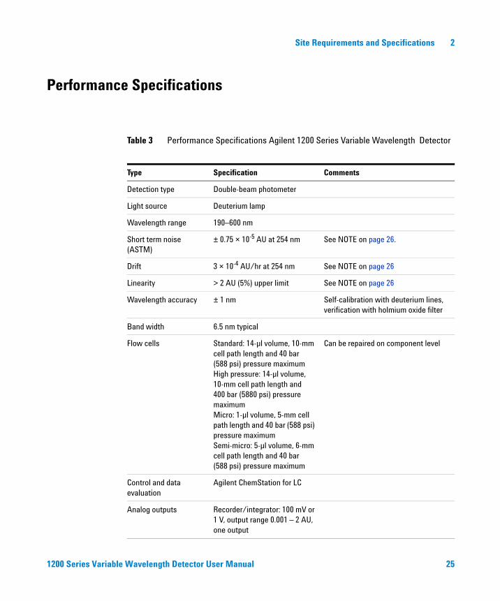
Table 3 Performance Specifications Agilent 1200 Series Variable Wavelength Detector
Type Specification Comments
Detection type Double-beam photometer
Light source Deuterium lamp
Wavelength range 190–600 nm
Short term noise (ASTM)
± 0.75 × 10⁻⁵ AU at 254 nm See NOTE on page 26.
Drift 3 × 10⁻⁴ AU/hr at 254 nm See NOTE on page 26
Linearity > 2 AU (5%) upper limit See NOTE on page 26
Wavelength accuracy ± 1 nm Self-calibration with deuterium lines, verification with holmium oxide filter
Band width 6.5 nm typical
Flow cells Standard: 14-µl volume, 10-mm cell path length and 40 bar (588 psi) pressure maximumHigh pressure: 14-µl volume,10-mm cell path length and 400 bar (5880 psi) pressure maximumMicro: 1-µl volume, 5-mm cell path length and 40 bar (588 psi) pressure maximumSemi-micro: 5-µl volume, 6-mm cell path length and 40 bar (588 psi) pressure maximum
Can be repaired on component level
Control and data evaluation
Agilent ChemStation for LC
Analog outputs Recorder/integrator: 100 mV or 1 V, output range 0.001 – 2 AU, one output
1200 Series Variable Wavelength Detector User Manual 25

2 Site Requirements and Specifications
Communications Controller-area network (CAN), GPIB, RS-232C, APG Remote: ready, start, stop and shut-down signals, LAN optional
GPIB for G1314B only
Safety and maintenance Extensive diagnostics, error detection and display (through control module and Agilent ChemStation), leak detection, safe leak handling, leak output signal for shutdown of pumping system. Low voltages in major maintenance areas.
GLP features Early maintenance feedback (EMF) for continuous tracking of instrument usage in terms of lamp burn time with user-settable limits and feedback messages. Electronic records of maintenance and errors. Verification of wavelength accuracy with built-in holmium oxide filter.
Housing All materials recyclable.
Table 3 Performance Specifications Agilent 1200 Series Variable Wavelength Detector (continued)
Type Specification Comments
NOTE ASTM: “Standard Practice for Variable Wavelength Photometric Detectors Used in Liquid Chromatography”.
Reference conditions: cell path length 10 mm, response time 2 s, flow 1 ml/min LC-grade methanol.
Linearity measured with caffeine at 265 nm.
26 1200 Series Variable Wavelength Detector User Manual

Agilent 1200 Series Variable Wavelength DetectorUser Manual
3Installing the Detector
Unpacking the Detector 28
Optimizing the Stack Configuration 30
Installing the Detector 33
Flow Connections to the Detector 36
This chapter describes the installation of the detector.
27Agilent Technologies

3 Installing the Detector
Unpacking the Detector
Damaged Packaging
If the delivery packaging shows signs of external damage, please call your Agilent Technologies sales and service office immediately. Inform your service representative that the detector may have been damaged during shipment.
Delivery Checklist
Ensure all parts and materials have been delivered with the detector. The delivery checklist is shown below. Please report missing or damaged parts to your local Agilent Technologies sales and service office.
CAUTION If there are signs of damage, please do not attempt to install the detector.
Table 4 Variable Wavelength Detector Checklist
Description Quantity
Variable wavelength detector 1
Power cable 1
Flow cell As ordered
User Manual 1
Accessory kit (see Table 5 on page 29) 1
28 1200 Series Variable Wavelength Detector User Manual

Installing the Detector 3
Detector Accessory Kit Contents
Table 5 Accessory Kit Contents
Description Part Number Quantity
Accessory kit G1314-68705
CAN cable 0.5 m 5181-1516 1
PEEK outlet capillary kit 5062-8535 1
Fitting male PEEK 0100-1516 1
Hex key 1.5 mm 8710-2393 1
Hex key 4 mm 8710-2392 1
Wrench open end 1/4 – 5/16 inch 8710-0510 1
Wrench open end 4 mm 8710-1534 1
1200 Series Variable Wavelength Detector User Manual 29

3 Installing the Detector
Optimizing the Stack Configuration
If your detector is part of a complete Agilent 1200 Series system, you can ensure optimum performance by installing the following configuration. This configuration optimizes the system flow path, ensuring minimum delay volume.
30 1200 Series Variable Wavelength Detector User Manual

Installing the Detector 3
Figure 5 Recommended Stack Configuration (Front View)
Solvent cabinet
Vacuum degasser
Pump
Column compartment
Autosampler
Detector
Local User Interface
1200 Series Variable Wavelength Detector User Manual 31
3 Installing the Detector
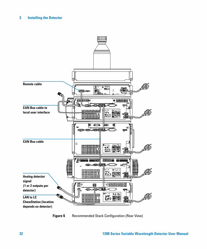
Figure 6 Recommended Stack Configuration (Rear View)
LAN to LC ChemStation (location depends on detector)
Remote cable
CAN Bus cable to local user interface
CAN Bus cable
Analog detector signal (1 or 2 outputs per detector)
32 1200 Series Variable Wavelength Detector User Manual

Installing the Detector 3
Installing the Detector
1 Install the LAN interface board in the detector (if required), see “Replacing the Interface Board" on page 99.
2 Place the detector in the stack or on the bench in a horizontal position.
3 Ensure the line power switch at the front of the detector is OFF.
Preparations Locate bench space.Provide power connections.Unpack the detector.
Parts required DetectorPower cord, for other cables see text below and “" on page 118ChemStation and/or Control Module G1323B
Figure 7 Front View of Detector
Line power switch with green light
Status indicator green/yellow/red
NOTE The figure above shows the flow cell already installed. The flow cell area is closed with a metal cover. The flow cell has to be installed as described in “Flow Connections to the Detector" on page 36.
1200 Series Variable Wavelength Detector User Manual 33

3 Installing the Detector
4 Connect the power cable to the power connector at the rear of the detector.
5 Connect the CAN cable to other Agilent 1200 Series modules.
6 If a Agilent ChemStation is the controller, connect either
• the LAN connection to the LAN interface board in the detector
7 Connect the analog cable (optional).
8 Connect the APG remote cable (optional) for non-Agilent 1200 Series instruments.
9 Turn ON power by pushing the button at the lower left-hand side of the detector. The status LED should be green.
NOTE If a Agilent 1200 DAD/MWD/FLD is in the system, the LAN should be connected to the DAD/MWD/FLD (due to higher data load).
Figure 8 Rear View of Detector
Analog signals
APG remote
RS-232C
CAN GPIB Power
Configuration switch
Interface board
Security lever
34 1200 Series Variable Wavelength Detector User Manual

Installing the Detector 3
NOTE The detector is turned ON when the line power switch is pressed and the green indicator lamp is illuminated. The detector is turned OFF when the line power switch is protruding and the green light is OFF.
WARNING To disconnect the detector from line, unplug the power cord. The power supply still uses some power, even if the power switch at the front panel is turned OFF.
NOTE The detector was shipped with default configuration settings.
1200 Series Variable Wavelength Detector User Manual 35

3 Installing the Detector
Flow Connections to the Detector
Preparations Detector is installed in the LC system.
Parts required Other modulesParts from accessory kit, see “Accessory Kit Contents" on page 29Two wrenches 1/4–5/16 inch for capillary connections
WARNING When working with solvents please observe appropriate safety procedures (for example, goggles, safety gloves and protective clothing) as described in the material handling and safety data sheet supplied by the solvent vendor, especially when using toxic or hazardous solvents.
NOTE The flow cell is shipped with a filling of isopropanol (also recommended when the instrument and/or flow cell is shipped to another location). This is to avoid breakage due to subambient conditions.
1 Press the release buttons and remove the front cover to have access to the flow cell area.
2 Remove the metal cover and install the flow cell. Tighten the cell screws.
36 1200 Series Variable Wavelength Detector User Manual
Installing the Detector 3
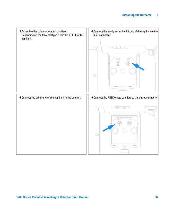
3 Assemble the column-detector capillary.Depending on the flow cell type it may be a PEEK or SST capillary.
4 Connect the newly assembled fitting of the capillary to the inlet connector.
5 Connect the other end of the capillary to the column. 6 Connect the PEEK waste capillary to the outlet connector.
1200 Series Variable Wavelength Detector User Manual 37

3 Installing the Detector
7 Establish a flow and observe for leakage. 8 Replace the front cover.
The installation of the detector is now complete.
NOTE The detector should be operated with the front cover in place to protect the flow cell area against strong drafts from the outside.
38 1200 Series Variable Wavelength Detector User Manual
Agilent 1200 Series Variable Wavelength DetectorUser Manual
4Using the Detector
Setting up an Analysis 40
Before Using the System 40
Requirements and Conditions 42
Optimization of the System 44
Preparing the HPLC System 45
Running the Sample and Verifying the Results 54
Special Settings of the Detector 55
Control Settings 55
Online Spectra 56
Scanning with the VWD 57
Analog Output Settings 59
Peakwidth Settings 61
Optimizing the Detector 63
This chapter provides information on how to set up the detector for an analysis and explains the basic settings.
39Agilent Technologies
4 Using the Detector
Setting up an Analysis
This chapter can be used for
• preparing the system,
• to learn the set up of an HPLC analysis and
• to use it as an instrument check to demonstrate that all modules of the system are correctly installed and connected. It is not a test of the instrument performance.
• Learn about special settings
Before Using the System
Solvent Information
Observe recommendations on the use of solvents in chapter “Solvents” in the pump’s reference manual.
Priming and Purging the System
When the solvents have been exchanged or the pumping system has been turned off for a certain time (for example, overnight) oxygen will re-diffuse into the solvent channel between the solvent reservoir, vacuum degasser (when available in the system) and the pump. Solvents containing volatile ingredients will slightly lose these. Therefore priming of the pumping system is required before starting an application.
40 1200 Series Variable Wavelength Detector User Manual
Using the Detector 4
1 Open the purge valve of your pump (by turning it counterclockwise) and set flow rate to 3-5 ml/min.
2 Flush all tubes with at least 30 ml of solvent.
3 Set flow to required value of your application and close the purge valve.
Pump for approximately 10 minutes before starting your application.
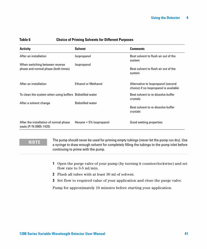
Table 6 Choice of Priming Solvents for Different Purposes
Activity Solvent Comments
After an installation
When switching between reverse phase and normal phase (both times)
Isopropanol
Isopropanol
Best solvent to flush air out of the system
Best solvent to flush air out of the system
After an installation Ethanol or Methanol Alternative to Isopropanol (second choice) if no Isopropanol is available
To clean the system when using buffers
After a solvent change
Bidistilled water
Bidistilled water
Best solvent to re-dissolve buffer crystals
Best solvent to re-dissolve buffer crystals
After the installation of normal phase seals (P/N 0905-1420)
Hexane + 5% Isopropanol Good wetting properties
NOTE The pump should never be used for priming empty tubings (never let the pump run dry). Use a syringe to draw enough solvent for completely filling the tubings to the pump inlet before continuing to prime with the pump.
1200 Series Variable Wavelength Detector User Manual 41

4 Using the Detector
Requirements and Conditions
What You Will Need
Table 7 lists the items you need to have for the set up of the analysis. Some of these are optional (not required for the basic system).
Table 7 What you will need
1200 system Pump (plus degassing)
Autosampler
Detector, standard flow cell installed
Agilent ChemStation (B.02.01 and above) orInstant Pilot G4208 (A.01.01 and above) (optional for basic operation) orControl Module G1323B (B.04.02 and above) (optional for basic operation), see note below.
System should be correctly set up for LAN communication with the Agilent ChemStation
Column: Zorbax Eclipse XDB-C18, 4.6 x 150 mm, 5 um Part No. 993967-902 or Part No. 5063-6600
Standard: Part No. 01080-687040.15 wt.% dimethylphthalate, 0.15 wt.% diethylphthalate, 0.01 wt.% biphenyl, 0.03 wt.% o-terphenyl in methanol
NOTE The G1314C VWD-SL can be operated with a G1323B Control Module just in standard mode as G1314B - no higher data rate selection is available.
42 1200 Series Variable Wavelength Detector User Manual

Using the Detector 4
Conditions
A single injection of the isocratic test standard is made under the conditions given in Table 8:
Table 8 Conditions
Flow 1.5 ml/minute
Stoptime 8 minutes
Solvent 100% (30% water/70% Acetonitrile)
Temperature Ambient
Wavelength sample 254 nm
Injection Volume 1 µl
1200 Series Variable Wavelength Detector User Manual 43
4 Using the Detector
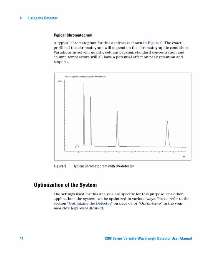
Typical Chromatogram
A typical chromatogram for this analysis is shown in Figure 9. The exact profile of the chromatogram will depend on the chromatographic conditions. Variations in solvent quality, column packing, standard concentration and column temperature will all have a potential effect on peak retention and response.
Optimization of the System
The settings used for this analysis are specific for this purpose. For other applications the system can be optimized in various ways. Please refer to the section “Optimizing the Detector" on page 63 or “Optimizing” in the your module’s Reference Manual.
Figure 9 Typical Chromatogram with UV-detector
44 1200 Series Variable Wavelength Detector User Manual

Using the Detector 4
Preparing the HPLC System
1 Turn on the Agilent ChemStation PC and the monitor.
2 Turn on the 1200 series HPLC modules.
3 Start the Agilent ChemStation software (B.02.01). If the pump, autosampler, thermostatted column compartment and detector are found, the ChemStation screen should look like shown in Figure 10.
The System status is red (Not Ready).
Figure 10 Initial ChemStation screen (Method and Run Control)
On-line plot window details window
System status
1200 Series Variable Wavelength Detector User Manual 45

4 Using the Detector
4 Turn on the detector lamp, pump and autosampler by clicking the System On button or the buttons below the module icons on the graphical user interface (GUI). After some time, the pump, thermostatted column compartment and detector module will turn to green.
Figure 11 Turning on the HPLC Module
46 1200 Series Variable Wavelength Detector User Manual

Using the Detector 4
5 Purge the pump. For more information see “Priming and Purging the System" on page 40.
6 Allow the detector to warm up of at least 60 minutes to provide a stable baseline (see example in Figure 12).
.
NOTE For reproducible chromatography, the detector and lamp should be on for at least one hour. Otherwise the detector baseline may still drift (depending on the environment).
Figure 12 Stabilization of Baseline
1200 Series Variable Wavelength Detector User Manual 47

4 Using the Detector
7 For the isocratic pump, fill the solvent bottle with the mixture of HPLC-grade bi-distilled water (30 %) and acetonitrile (70 %). For binary- and quaternary pumps you can use separate bottles.
8 Click on the Load Method button and select DEF_LC.M and press OK. Alternative double-click on the method in the method window. The default LC method parameters are transferred into the 1200 modules.
Figure 13 Loading Default LC Method
48 1200 Series Variable Wavelength Detector User Manual
Using the Detector 4
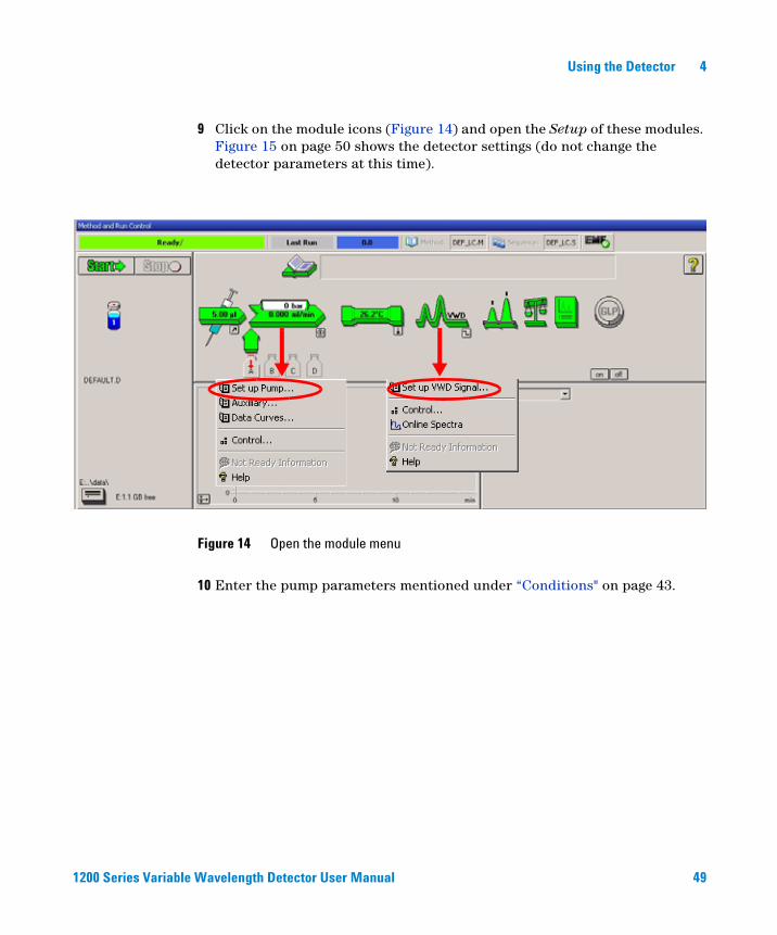
9 Click on the module icons (Figure 14) and open the Setup of these modules. Figure 15 on page 50 shows the detector settings (do not change the detector parameters at this time).
10 Enter the pump parameters mentioned under “Conditions" on page 43.
Figure 14 Open the module menu
1200 Series Variable Wavelength Detector User Manual 49
4 Using the Detector
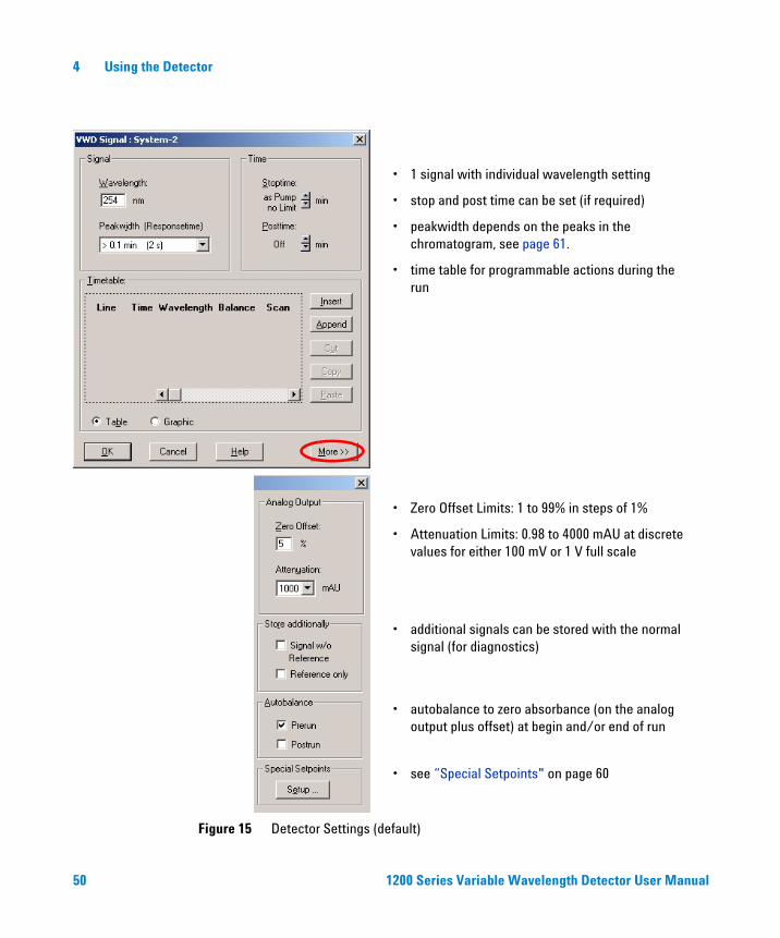
Figure 15 Detector Settings (default)
• 1 signal with individual wavelength setting
• stop and post time can be set (if required)
• peakwidth depends on the peaks in the chromatogram, see page 61.
• time table for programmable actions during the run
• Zero Offset Limits: 1 to 99% in steps of 1%
• Attenuation Limits: 0.98 to 4000 mAU at discrete values for either 100 mV or 1 V full scale
• see “Special Setpoints" on page 60
• autobalance to zero absorbance (on the analog output plus offset) at begin and/or end of run
• additional signals can be stored with the normal signal (for diagnostics)
50 1200 Series Variable Wavelength Detector User Manual

Using the Detector 4
11 Pump the water/acetonitrile (30/70 %) mobile phase through the column for 10 minutes for equilibration.
12 Click the button and select Change... to open the Signal Plot information. Select the Pump: Pressure and the VWD A: Signal 254 as signals. Change the Y-range for the VWD to 1 mAU and the offset to 20% and the pressure offset to 50%. The X-axis range should be 15 minutes. Press OK to exit this screen.
Figure 16 Edit Signal Plot Window
1200 Series Variable Wavelength Detector User Manual 51
4 Using the Detector
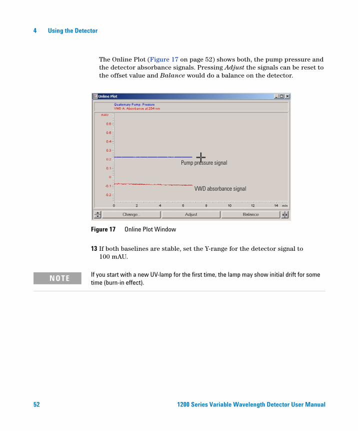
The Online Plot (Figure 17 on page 52) shows both, the pump pressure and the detector absorbance signals. Pressing Adjust the signals can be reset to the offset value and Balance would do a balance on the detector.
13 If both baselines are stable, set the Y-range for the detector signal to 100 mAU.
Figure 17 Online Plot Window
Pump pressure signal
VWD absorbance signal
NOTE If you start with a new UV-lamp for the first time, the lamp may show initial drift for some time (burn-in effect).
52 1200 Series Variable Wavelength Detector User Manual

Using the Detector 4
14 Select the menu item RunControl -> Sample Info and enter information about this application (Figure 18 on page 53). Press OK to leave this screen.
15 Fill the content of an isocratic standard sample ampoule into a vial and seal the vial with a cap and place the vial into autosampler tray (position #1).
Figure 18 Sample Information
1200 Series Variable Wavelength Detector User Manual 53

4 Using the Detector
Running the Sample and Verifying the Results
1 To start a run select the menu item RunControl -> Run Method.
2 This will start the 1200 modules and the online plot on the Agilent ChemStation will show the resulting chromatogram.
Figure 19 Chromatogram with Isocratic Test Sample
NOTE Information about using the Data Analysis functions can be obtained from the Using your ChemStation manual supplied with your system.
54 1200 Series Variable Wavelength Detector User Manual
Using the Detector 4
Special Settings of the Detector
In this chapter special settings of the G1314B VWD and G1314C VWD-SL are described (based on the Agilent ChemStation B.02.01).
Control Settings
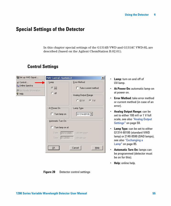
Figure 20 Detector control settings
• Lamp: turn on and off of UV-lamp.
• At Power On: automatic lamp-on at power on.
• Error Method: take error method or current method (in case of an error).
• Analog Output Range: can be set to either 100 mV or 1 V full scale, see also “Analog Output Settings" on page 59.
• Lamp Type: can be set to either G1314-60100 (standard VWD lamp) or 2140-0590 (DAD lamps), see also “Exchanging a Lamp" on page 85.
• Automatic Turn On: lamps can be programmed (detector must be on for this).
• Help: online help.
1200 Series Variable Wavelength Detector User Manual 55

4 Using the Detector
Online Spectra
1 To view the online spectra select Online Spectra.
2 Change the absorbance and wavelength range according your needs.
NOTE This online spectrum is taken during a stop-flow condition only while the peak is kept in the flow cell, see “Scanning with the VWD" on page 57.
Figure 21 Online Spectra Window
56 1200 Series Variable Wavelength Detector User Manual
Using the Detector 4
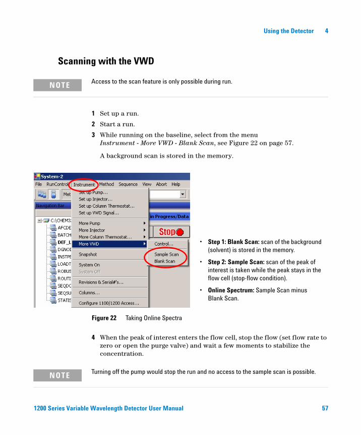
Scanning with the VWD
1 Set up a run.
2 Start a run.
3 While running on the baseline, select from the menuInstrument - More VWD - Blank Scan, see Figure 22 on page 57.
A background scan is stored in the memory.
4 When the peak of interest enters the flow cell, stop the flow (set flow rate to zero or open the purge valve) and wait a few moments to stabilize the concentration.
NOTE Access to the scan feature is only possible during run.
Figure 22 Taking Online Spectra
• Step 1: Blank Scan: scan of the background (solvent) is stored in the memory.
• Step 2: Sample Scan: scan of the peak of interest is taken while the peak stays in the flow cell (stop-flow condition).
• Online Spectrum: Sample Scan minus Blank Scan.
NOTE Turning off the pump would stop the run and no access to the sample scan is possible.
1200 Series Variable Wavelength Detector User Manual 57
4 Using the Detector
5 Select from the menuInstrument - More VWD - Sample Scan.
A sample scan is taken in the range defined under “Special Setpoints" on page 60 and the Online Spectra window (see “Online Spectra" on page 56) displays the result (Sample Scan minus Blank Scan).
58 1200 Series Variable Wavelength Detector User Manual

Using the Detector 4
Analog Output Settings
1 To change the Output Range of the analog outputs select VWD Control.
2 To change the offset and the attenuation select VWD Signal - More.
3 Change the values if required.
Figure 23 Analog Output Settings
• Analog Output Range: can be set to either 100 mV or 1 V full scale.
• Zero Offset: can be set to either 100 mV or 1 V full scale.
• Attenuation Limits: 0.98 to 4000 mAU at discrete values for either 100 mV or 1 V full scale.
1200 Series Variable Wavelength Detector User Manual 59

4 Using the Detector
Special Setpoints
1 To change the offset and the attenuation select VWD Signal - More - Special Setpoints.
Figure 24 Spectra Window
Margin for negative Absorbance: Use this field to modify the detector’s signal handling to increase the margin for negative absorbance. Use this option if, for example, your solvent gradient produces a decreasing baseline absorbance, and for GPC analyses.
Limits: 100 to 4000 mAU.
Signal Polarity: can be switched to negative (if required).
Enable analysis when lamp is off: if the VWD is not used in a dual detector setup (lamp off), the not-ready condition is not stopping the analysis.
Scan Range / Step: Used for stop-flow scanning, see “Scanning with the VWD" on page 57.
NOTE Margin for negative Absorbance: The higher the value the greater the baseline noise. Set this value only if you expect negative absorbance greater than -100 mAU.
60 1200 Series Variable Wavelength Detector User Manual

Using the Detector 4
Peakwidth Settings
1 To change the Peakwidth settings select Setup Detector Signals.
2 In the section Peakwidth (Responsetime) click on the drop-down list.
3 Change the Peakwidth according to your needs.
NOTE Do not use peak width shorter than necessary, see also “Set the Detector Parameters" on page 69.
Figure 25 Peakwidth Setting
Peakwidth enables you to select the peak width (response time) for your analysis. The peak width is defined as the width of a peak, in minutes, at half the peak height. Set the peak width to the narrowest expected peak in your chromatogram. The peak width sets the optimum response time for your detector. The peak detector ignores any peaks that are considerably narrower, or wider, than the peak width setting. The response time is the time between 10% and 90% of the output signal in response to an input step function. When the All spectrum storage option is selected, then spectra are acquired continuously depending on the setting of the peak width. The time specified by the peak width is used as a factor in the acquisition of spectra. The acquisition time for one spectrum is slightly less than the peak width divided by 8, see Table 9 on page 62.
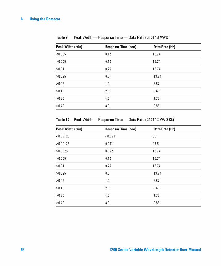
Limits: When you set the peak width (in minutes), the corresponding response time is set automatically and the appropriate data rate for signal acquisition is selected as shown in Table 9 on page 62.
1200 Series Variable Wavelength Detector User Manual 61
4 Using the Detector
Table 9 Peak Width — Response Time — Data Rate (G1314B VWD)
Peak Width (min) Response Time (sec) Data Rate (Hz)
<0.005 0.12 13.74
>0.005 0.12 13.74
>0.01 0.25 13.74
>0.025 0.5 13.74
>0.05 1.0 6.87
>0.10 2.0 3.43
>0.20 4.0 1.72
>0.40 8.0 0.86
Table 10 Peak Width — Response Time — Data Rate (G1314C VWD SL)
Peak Width (min) Response Time (sec) Data Rate (Hz)
<0.00125 <0.031 55
>0.00125 0.031 27.5
>0.0025 0.062 13.74
>0.005 0.12 13.74
>0.01 0.25 13.74
>0.025 0.5 13.74
>0.05 1.0 6.87
>0.10 2.0 3.43
>0.20 4.0 1.72
>0.40 8.0 0.86
62 1200 Series Variable Wavelength Detector User Manual

Using the Detector 4
Optimizing the Detector
Additional theoretical information can be found in chapter “How to optimize the detector" on page 65.
1200 Series Variable Wavelength Detector User Manual 63

4 Using the Detector
64 1200 Series Variable Wavelength Detector User Manual

Agilent 1200 Series Variable Wavelength DetectorUser Manual
5How to optimize the detector
Optimizing the Detector Performance 66
This chapter gives hints on how to select the detector parameters and the flow cell.
65Agilent Technologies

5 How to optimize the detector
Optimizing the Detector Performance
The detector has a variety of parameters that can be used to optimize performance.
The information below will guide you on how to get the best detector performance. Follow these rules as a start for new applications. It gives a rule-of-thumb for optimizing the detector parameters.
Match the Flow Cell to the Column
Figure 26 recommends the flow cell that matches the column used. If more than one selection is appropriate, use the larger flow cell to get the best detection limit. Use the smaller flow cell for best peak resolution.
Figure 26 Choosing a Flow Cell
Typical peak width
Column length Recommended flow cell
Internal column diameter
Typical flow rate 0.05 – 0.2 ml/min
1.0 mm 2.1 mm 3.0 mm 4.6 mm
0.2 – 0.4 ml/min 0.4 – 0.8 ml/min 1 – 2 ml/min
<= 5 cm
10 cm
20 cm
>= 40 cm
0.025 min
0.05 min
0.1 min
0.2 min
Microflow cell
Standardflow cell
Semi-microflow cell
66 1200 Series Variable Wavelength Detector User Manual

How to optimize the detector 5
Flow Cell Path Length
Lambert-Beer’s law shows a linear relationship between the flow cell path length and absorbance.
whereT is the transmission, defined as the quotient of the intensity of the
transmitted light I divided by the intensity of the incident light, I0,
ε is the extinction coefficient, which is a characteristic of a given substance under a precisely-defined set of conditions of wavelength, solvent, temperature and other parameters,
C is the concentration of the absorbing species (usually in g/l or mg/l), andd is the path length of the cell used for the measurement.
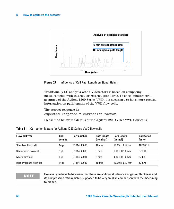
Therefore, flow cells with longer path lengths yield higher signals. Although noise usually increases little with increasing path length, there is a gain in signal-to-noise ratio. For example, in Figure 27 on page 68 the noise increased by less than 10 % but a 70 % increase in signal intensity was achieved by increasing the path length from 6 mm to 10 mm.
When increasing the path length, the cell volume usually increases — in our example from 5 – 13 µl. Typically, this causes more peak dispersion. As Figure 27 on page 68 demonstrates, this did not affect the resolution in the gradient separation in our example.
As a rule-of-thumb the flow cell volume should be about 1/3 of the peak volume at half height. To determine the volume of your peaks, take the peak width as reported in the integration results multiply it by the flow rate and divide it by 3).
Absorbance Tlog–I0I----log ε C d⋅ ⋅= = =
1200 Series Variable Wavelength Detector User Manual 67
5 How to optimize the detector
Traditionally LC analysis with UV detectors is based on comparing measurements with internal or external standards. To check photometric accuracy of the Agilent 1200 Series VWD it is necessary to have more precise information on path lengths of the VWD flow cells.
The correct response is:expected response * correction factor
Please find below the details of the Agilent 1200 Series VWD flow cells:
Figure 27 Influence of Cell Path Length on Signal Height
Abs
orba
nce
Time (min)
Analysis of pesticide standard
10-mm optical path length
6-mm optical path length
Table 11 Correction factors for Agilent 1200 Series VWD flow cells
Flow cell type Cellvolume
Part number Path length(nominal)
Path length(actual)
Correctionfactor
Standard flow cell 14 µl G1314-60086 10 mm 10.15 ± 0.19 mm 10/10.15
Semi-micro flow cell 5 µl G1314-60083 6 mm 6.10 ± 0.19 mm 6/6.10
Micro flow cell 1 µl G1314-60081 5 mm 4.80 ± 0.19 mm 5/4.8
High Pressure flow cell 14 µl G1314-60082 10 mm 10.00 ± 0.19 mm 6/5.75
NOTE However you have to be aware that there are additional tolerance of gasket thickness and its compression ratio which is supposed to be very small in comparison with the machining tolerance.
68 1200 Series Variable Wavelength Detector User Manual

How to optimize the detector 5
Set the Detector Parameters
1 Set peakwidth as close as possible to the width (at half height) of a narrow peak of interest.
2 Choose the sample wavelength.
• at a longer wavelength than the cut-off wavelength of the mobile phase,
• at a wavelength where the analytes have strong absorptivity if you want to get the lowest possible detection limit,
• at a wavelength with moderate absorptivity if you work with high concentrations, and
• preferably where the spectrum is flat for better linearity.
3 Consider to use time-programming to further optimization.
Table 12 Peakwidth Settings
Peakwidth at half height Rise time [10.. 90%] Data rate Module
< 0.00125 minutes < 0.031 seconds 54.96 Hz G1314C
0.00125 minutes 0.031 seconds 27.48 Hz G1314C
0.0025 minutes 0.062 seconds 13.74 Hz G1314C
0.005 minutes 0.125 seconds 13.74 Hz G1314B / G1314C
0.01 minutes 0.25 seconds 13.74 Hz G1314B / G1314C
0.025 minutes 0.50 seconds 13.74 Hz G1314B / G1314C
0.05 minutes 1 second 6.87 Hz G1314B / G1314C
0.1 minutes 2 seconds 3.43 Hz G1314B / G1314C
0.2 minutes 4 seconds 1.72 Hz G1314B / G1314C
0.4 minutes 8 seconds 0.86 Hz G1314B / G1314C
NOTE The G1314C VWD-SL can be operated with a G1323B just in standard mode as G1314B - no higher data rate selection is available.
1200 Series Variable Wavelength Detector User Manual 69

5 How to optimize the detector
70 1200 Series Variable Wavelength Detector User Manual

Agilent 1200 Series Variable Wavelength DetectorUser Manual
6Troubleshooting and Diagnostics
Overview of the Detector’s Indicators and Test Functions 72
Status Indicators 73
User Interfaces 75
Agilent LC Diagnostic Software 76
Overview about the troubleshooting and diagnostic features.
71Agilent Technologies

6 Troubleshooting and Diagnostics
Overview of the Detector’s Indicators and Test Functions
Status Indicators
The detector is provided with two status indicators which indicate the operational state (prerun, run, and error states) of the detector. The status indicators provide a quick visual check of the operation of the detector (see page 51).
Error Messages
In the event of an electronic, mechanical or hydraulic failure, the detector generates an error message in the user interface. For each message, a short description of the failure, a list of probable causes of the problem, and a list of suggested actions to fix the problem are provided (see “Troubleshooting and Diagnostics”in the Service Manual.).
Test Functions
A series of test functions are available for troubleshooting and operational verification after exchanging internal components (see “Test Functions” in the Service Manual).
Wavelength Verification / Recalibration
Wavelength recalibration is recommended after repair of internal components, and on a regular basis to ensure correct operation of the detector. The detector uses the deuterium alpha and beta emission lines for wavelength calibration (see “Wavelength Verification/Calibration” on page 104).
Diagnostic Signals
The detector has several signals (internal temperatures, voltages and currents of lamps) that can be used for diagnosing baseline problems (see “Diagnosis Signals” in the Service Manual).
72 1200 Series Variable Wavelength Detector User Manual
Troubleshooting and Diagnostics 6
Status Indicators
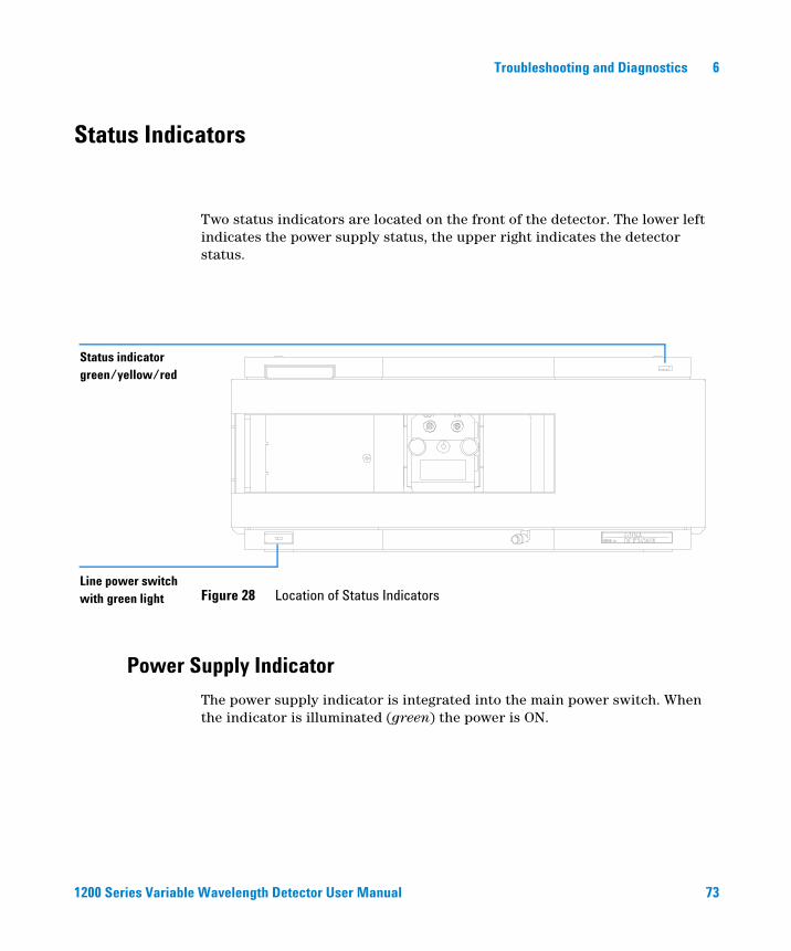
Two status indicators are located on the front of the detector. The lower left indicates the power supply status, the upper right indicates the detector status.
Power Supply Indicator
The power supply indicator is integrated into the main power switch. When the indicator is illuminated (green) the power is ON.
Figure 28 Location of Status IndicatorsLine power switch with green light
Status indicator green/yellow/red
1200 Series Variable Wavelength Detector User Manual 73
6 Troubleshooting and Diagnostics
Detector Status Indicator
The detector status indicator indicates one of four possible detector conditions:
• When the status indicator is OFF (and power switch light is on), the detector is in a prerun condition, and is ready to begin an analysis.
• A green status indicator, indicates the detector is performing an analysis (run mode).
• A yellow indicator indicates a not-ready condition. The detector is in a not-ready state when it is waiting for a specific condition to be reached or completed (for example, immediately after changing a set point), or while a self-test procedure is running.
• An error condition is indicated when the status indicator is red. An error condition indicates the detector has detected an internal problem which affects correct operation of the detector. Usually, an error condition requires attention (e.g. leak, defective internal components). An error condition always interrupts the analysis.
• A red-blinking indicator indicates that the module is in resident mode (e.g. during update of main firmware).
74 1200 Series Variable Wavelength Detector User Manual

Troubleshooting and Diagnostics 6
User Interfaces
Depending on the user interface the available tests vary. All test descriptions are based on the Agilent ChemStation as user interface. Some descriptions are only available in the Service Manual.
Table 13 Test Functions available vs. User Interface
Test ChemStation Instant PilotG4208A
Control Module G1323B
Selftest Yes No No
Filter Yes No No
Slit Yes No Yes
D/A Converter Yes No No
Test Chromatogram Yes (C) No Yes
Wavelength Calibration Yes Yes (M) Yes
Lamp Intensity Yes Yes (D) Yes
Holmium Yes Yes (D) Yes
Cell Yes Yes (D) No
Dark Current Yes Yes (D) No
C via command
M section Maintenance
D section Diagnose
NOTE The Agilent Control Module (G1323B) does not do any calculations. So there will be no reports generated with passed/failed information.
1200 Series Variable Wavelength Detector User Manual 75
6 Troubleshooting and Diagnostics
Agilent LC Diagnostic Software
The Agilent LC diagnostic software is an application independent tool that provides troubleshooting capabilities for the Agilent 1200 Series modules. It provides for all 1200 Series LC the possibility of a first guided diagnostic for typical HPLC symptoms and a status report stored as Adobe Acrobat pdf or as a printable file to assist users evaluating the instrument state.
At the introduction, following modules will be fully supported by the software, including module tests and calibrations as well as injector steps and maintenance positions.
• Agilent 1200 Series binary pump SL (G1312B)
• Agilent 1200 Series high performance autosampler SL (G1367B)
• Agilent 1200 Series thermostatted column compartment SL (G1316B)
• Agilent 1200 Series diode array detector SL (G1315C)
With further releases of the diagnostic software all Agilent 1200 Series HPLC modules will be fully supported.
This diagnostic software provides tests and diagnostic features that may differ from the descriptions in this manual. For details refer to the help files provided with the diagnostic software.
76 1200 Series Variable Wavelength Detector User Manual
Agilent 1200 Series Variable Wavelength DetectorUser Manual
7Maintenance and Repair
Introduction to Maintenance and Repair 78
Warnings and Cautions 79
Cleaning the Detector 80
Using the ESD Strap 81
This chapter provides general information on maintenance and repair of the detector.
77Agilent Technologies

7 Maintenance and Repair
Introduction to Maintenance and Repair
Simple Repairs - Maintenance
The detector is designed for easy repair. The most frequent repairs such as lamp change and flow cell change can be done from the front of the detector with the detector in place in the system stack. These repairs are described in “Maintenance” on page 83 (part of the User Manual and Service Manual).
Exchanging Internal Parts - Repair
Some repairs may require exchange of defective internal parts. Exchange of these parts requires removing the detector from the stack, removing the covers, and disassembling the detector. The security lever at the power input socket prevents that the detector cover is taken off when line power is still connected. These repairs are described in “Repair” in the Service Manual.
78 1200 Series Variable Wavelength Detector User Manual
Maintenance and Repair 7
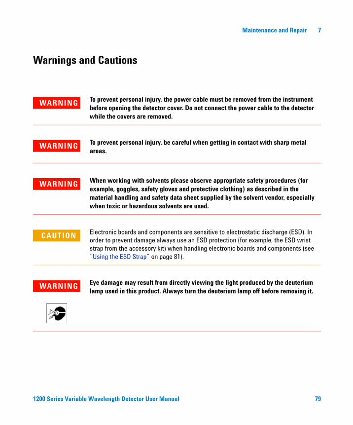
Warnings and Cautions
WARNING To prevent personal injury, the power cable must be removed from the instrument before opening the detector cover. Do not connect the power cable to the detector while the covers are removed.
WARNING To prevent personal injury, be careful when getting in contact with sharp metal areas.
WARNING When working with solvents please observe appropriate safety procedures (for example, goggles, safety gloves and protective clothing) as described in the material handling and safety data sheet supplied by the solvent vendor, especially when toxic or hazardous solvents are used.
CAUTION Electronic boards and components are sensitive to electrostatic discharge (ESD). In order to prevent damage always use an ESD protection (for example, the ESD wrist strap from the accessory kit) when handling electronic boards and components (see “Using the ESD Strap” on page 81).
WARNING Eye damage may result from directly viewing the light produced by the deuterium lamp used in this product. Always turn the deuterium lamp off before removing it.
1200 Series Variable Wavelength Detector User Manual 79

7 Maintenance and Repair
Cleaning the Detector
The detector case should be kept clean. Cleaning should be done with a soft cloth slightly dampened with water or a solution of water and mild detergent. Do not use an excessively damp cloth allowing liquid to drip into the detector.
WARNING Do not let liquid drip into the detector. It could cause shock hazard and it could damage the detector.
80 1200 Series Variable Wavelength Detector User Manual

Maintenance and Repair 7
Using the ESD Strap
Electronic boards are sensitive to electrostatic discharge (ESD). In order to prevent damage, always use an ESD strap when handling electronic boards and components.
1 Unwrap the first two folds of the band and wrap the exposed adhesive side firmly around your wrist.
2 Unroll the rest of the band and peel the liner from the copper foil at the opposite end.
3 Attach the copper foil to a convenient and exposed electrical ground.
Figure 29 Using the ESD Strap
1200 Series Variable Wavelength Detector User Manual 81

7 Maintenance and Repair
82 1200 Series Variable Wavelength Detector User Manual

Agilent 1200 Series Variable Wavelength DetectorUser Manual
8Maintenance
Overview of Maintenance 84
Exchanging a Lamp 85
Exchanging a Flow Cell 87
Repairing the Flow Cells 90
Using the Cuvette Holder 94
Correcting Leaks 97
Replacing Leak Handling System Parts 98
Replacing the Interface Board 99
Replacing the Detector’s Firmware 100
Tests & Calibrations 101
Intensity Test 102
Wavelength Verification/Calibration 104
Holmium Oxide Test 105
This chapter describes the maintenance of the detector.
83Agilent Technologies
8 Maintenance
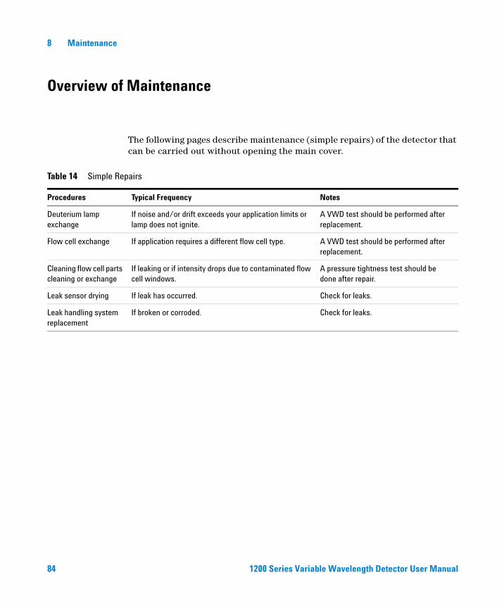
Overview of Maintenance
The following pages describe maintenance (simple repairs) of the detector that can be carried out without opening the main cover.
Table 14 Simple Repairs
Procedures Typical Frequency Notes
Deuterium lamp exchange
If noise and/or drift exceeds your application limits or lamp does not ignite.
A VWD test should be performed after replacement.
Flow cell exchange If application requires a different flow cell type. A VWD test should be performed after replacement.
Cleaning flow cell parts cleaning or exchange
If leaking or if intensity drops due to contaminated flow cell windows.
A pressure tightness test should be done after repair.
Leak sensor drying If leak has occurred. Check for leaks.
Leak handling system replacement
If broken or corroded. Check for leaks.
84 1200 Series Variable Wavelength Detector User Manual

Maintenance 8
Exchanging a Lamp
When required If noise or drift exceeds application limits or lamp does not ignite.
Tools required Screwdriver POZI 1 PT3
Parts required Deuterium lamp G1314-60100
NOTE If you want to use the Agilent DAD lamp instead of the VWD lamp, you have to change the lamp settings in the VWD Configuration to lamp type 2140-0590. This ensures that the DAD lamp’s filament heating is operated like in the DAD. The instrument specifications are based on the VWD lamp.
WARNING If the detector has been in use, the lamp may be hot. If so, wait five minutes for lamp to cool down.
Preparations for this procedure:
• Turn the lamp OFF.
1 Press the release buttons and remove the front cover to have access to the lamp area.
1200 Series Variable Wavelength Detector User Manual 85
8 Maintenance
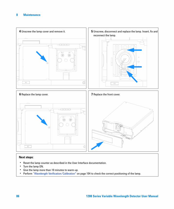
4 Unscrew the lamp cover and remove it. 5 Unscrew, disconnect and replace the lamp. Insert, fix and reconnect the lamp.
6 Replace the lamp cover. 7 Replace the front cover.
Next steps:
• Reset the lamp counter as described in the User Interface documentation.• Turn the lamp ON.• Give the lamp more than 10 minutes to warm-up.• Perform “Wavelength Verification/Calibration" on page 104 to check the correct positioning of the lamp.
86 1200 Series Variable Wavelength Detector User Manual
Maintenance 8
Exchanging a Flow Cell
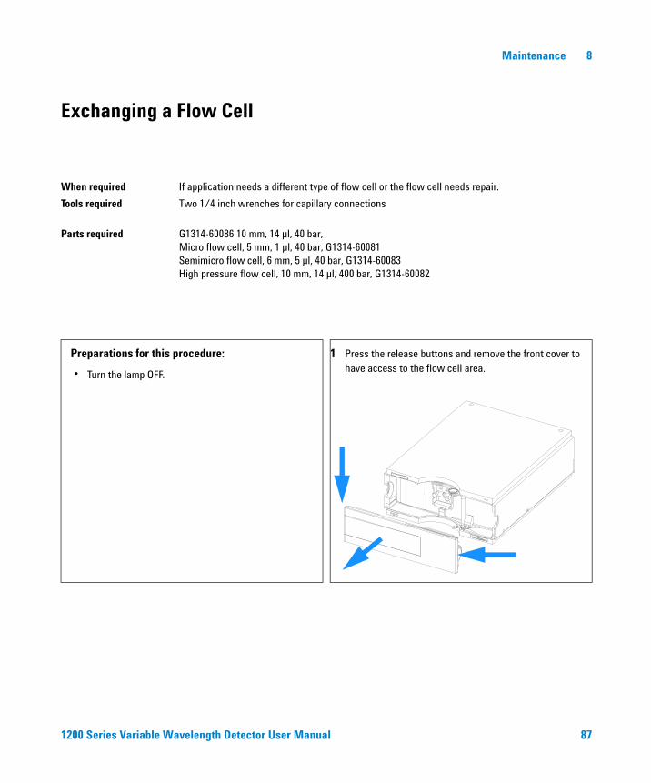
When required If application needs a different type of flow cell or the flow cell needs repair.
Tools required Two 1/4 inch wrenches for capillary connections
Parts required G1314-60086 10 mm, 14 µl, 40 bar, Micro flow cell, 5 mm, 1 µl, 40 bar, G1314-60081Semimicro flow cell, 6 mm, 5 µl, 40 bar, G1314-60083High pressure flow cell, 10 mm, 14 µl, 400 bar, G1314-60082
Preparations for this procedure:
• Turn the lamp OFF.
1 Press the release buttons and remove the front cover to have access to the flow cell area.
1200 Series Variable Wavelength Detector User Manual 87

8 Maintenance
2 Disconnect the inlet and outlet capillaries. 3 Unscrew the thumb screws parallel and remove the flow cell.
Note:
If you want to maintain flow cell parts, see “Repairing the Flow Cells" on page 90 or the information provided with your flow cell.
4 Replace the flow cell and fix the thumb screws. Reconnect the inlet and outlet capillaries to the flow cell.
88 1200 Series Variable Wavelength Detector User Manual

Maintenance 8
5 Replace the front cover. Next steps:
• To check for leaks, establish a flow and observe the flow cell (outside of the cell compartment) and all capillary connections.
• Insert the flow cell.• Perform “Wavelength Verification/Calibration" on
page 104 to check the correct positioning of the flow cell.
• Replace the front cover.
1200 Series Variable Wavelength Detector User Manual 89

8 Maintenance
Repairing the Flow Cells
When required If the flow cell needs repair due to leaks or contaminations.
Tools required Wrench 1/4 inch for capillary connectionsHexagonal wrench 4 mmTooth picks
Parts required See “Standard Flow Cell" on page 111.See “Micro Flow Cell" on page 112.See “Semi-micro Flow Cell" on page 113.See “High Pressure Flow Cell" on page 115.
Preparations Turn off the flow.Remove the front cover.Remove the flow cell, see “Exchanging a Flow Cell" on page 87.
NOTE The shown cell parts will differ depending upon the flow cell type. For detailed parts schematics, refer to above mentioned pages.
Figure 30 Standard Flow Cell
1 - Cell Screw2 - Conical Springs3 - Ring #1 PEEK4 - Gasket #1 (small hole)5 - Window Quartz6 - Gasket #2 (large hole)7 - Cell cover assembly8 - Ring #2 PEEK
12
3
54
65
82
1
7
90 1200 Series Variable Wavelength Detector User Manual

Maintenance 8
Disassemblingthe Flow Cell
1 Unscrew the cell screw using a 4-mm hexagonal wrench.
2 Remove the SST rings using a pair of tweezers.
3 Use adhesive tape to remove the peek ring, the window and the gasket.
4 Repeat step 1 through step 3 for the other window (keep the parts separate - otherwise they could be mixed!).
Cleaning the FlowCell Parts
5 Pour isopropanol into the cell hole and wipe clean with a piece of lint-free cloth.
6 Clean the windows with ethanol or methanol. Dry it with a piece of lint-free cloth.
Reassembling theFlow Cell
7 Hold the flow cell cassette horizontally and place gasket in position. Ensure both cell holes can be seen through the holes of gasket.
8 Place the window on gasket.
9 Place the peek ring on the window.
10 Insert the conical springs. Make sure the conical springs point towards the window. Otherwise tightening the cell screw might break the window.
11 Screw the cell screw into the flow cell and tighten the screw.
12 Repeat the procedure for the other cell side.
CAUTION Do not use tweezers to remove windows as the surfaces can easily be scratched.
NOTE Always use new gaskets.
NOTE The semi-micro #1 and #2 gaskets (items 6 and 7, “Semi-micro Flow Cell" on page 114) look very similar. Do not mix them up.
1200 Series Variable Wavelength Detector User Manual 91

8 Maintenance
Next steps • Reconnect the capillaries, see “Exchanging a Flow Cell" on page 87.
• Perform a leak test. If OK, insert the flow cell.
• Perform “Wavelength Verification/Calibration" on page 104 to check the correct positioning of the flow cell.
• Replace the front cover.
92 1200 Series Variable Wavelength Detector User Manual
Maintenance 8
Using the Cuvette Holder
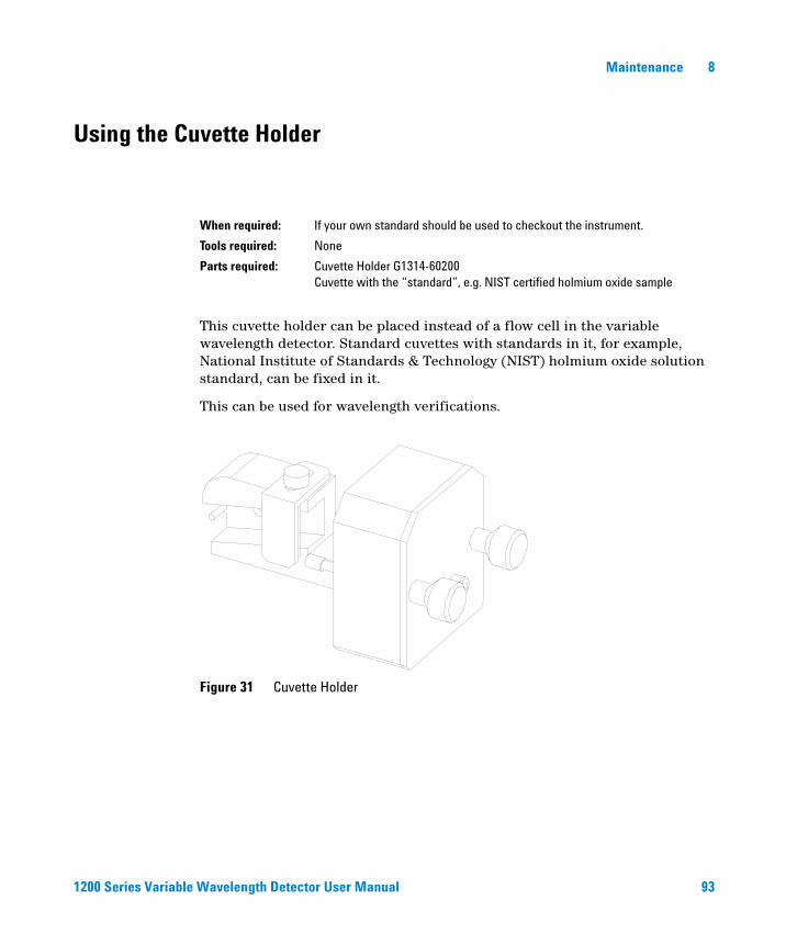
This cuvette holder can be placed instead of a flow cell in the variable wavelength detector. Standard cuvettes with standards in it, for example, National Institute of Standards & Technology (NIST) holmium oxide solution standard, can be fixed in it.
This can be used for wavelength verifications.
When required: If your own standard should be used to checkout the instrument.
Tools required: None
Parts required: Cuvette Holder G1314-60200Cuvette with the “standard”, e.g. NIST certified holmium oxide sample
Figure 31 Cuvette Holder
1200 Series Variable Wavelength Detector User Manual 93
8 Maintenance
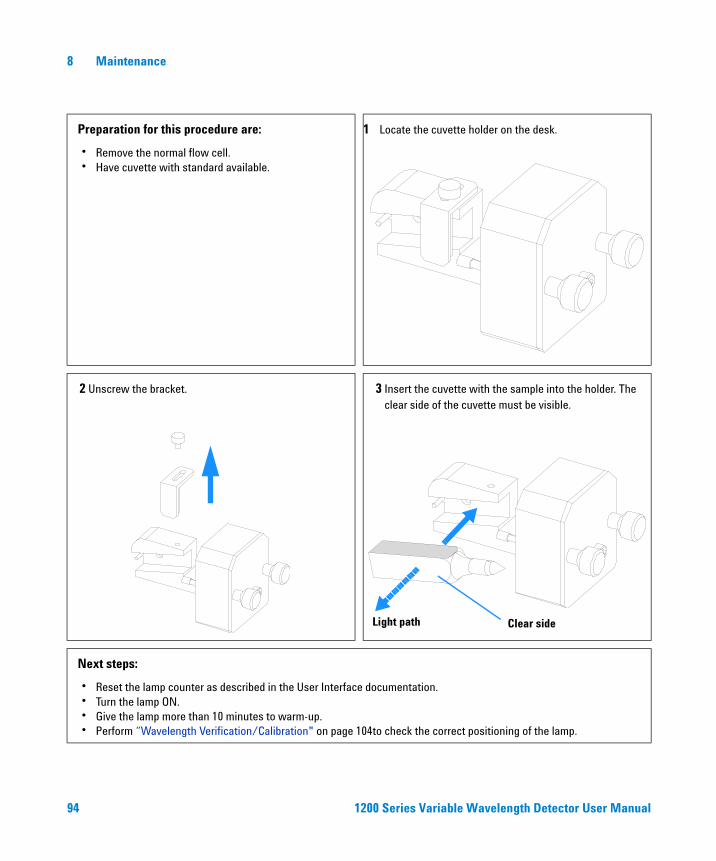
Preparation for this procedure are:
• Remove the normal flow cell.• Have cuvette with standard available.
1 Locate the cuvette holder on the desk.
2 Unscrew the bracket. 3 Insert the cuvette with the sample into the holder. The clear side of the cuvette must be visible.
Next steps:
• Reset the lamp counter as described in the User Interface documentation.• Turn the lamp ON.• Give the lamp more than 10 minutes to warm-up.• Perform “Wavelength Verification/Calibration" on page 104to check the correct positioning of the lamp.
Light path Clear side
94 1200 Series Variable Wavelength Detector User Manual
Maintenance 8
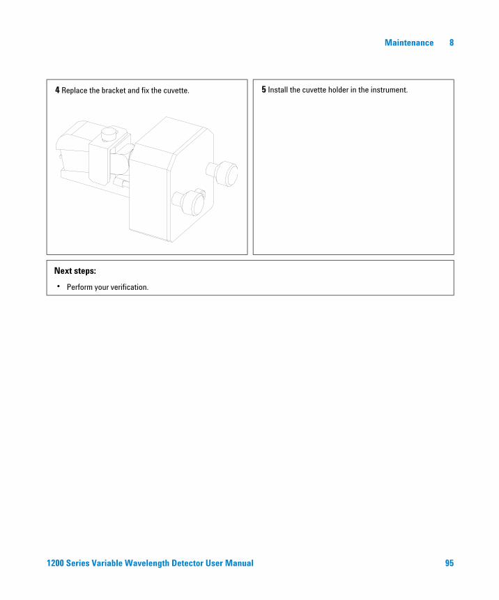
4 Replace the bracket and fix the cuvette. 5 Install the cuvette holder in the instrument.
Next steps:
• Perform your verification.
1200 Series Variable Wavelength Detector User Manual 95
8 Maintenance
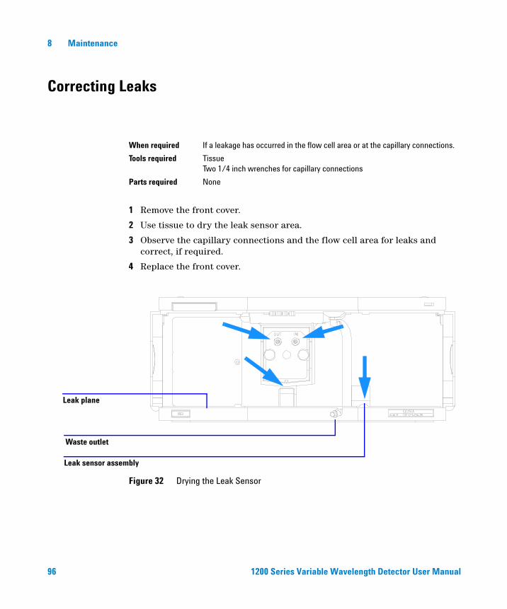
Correcting Leaks
1 Remove the front cover.
2 Use tissue to dry the leak sensor area.
3 Observe the capillary connections and the flow cell area for leaks and correct, if required.
4 Replace the front cover.
When required If a leakage has occurred in the flow cell area or at the capillary connections.
Tools required TissueTwo 1/4 inch wrenches for capillary connections
Parts required None
Figure 32 Drying the Leak Sensor
Waste outlet
Leak plane
Leak sensor assembly
96 1200 Series Variable Wavelength Detector User Manual
Maintenance 8
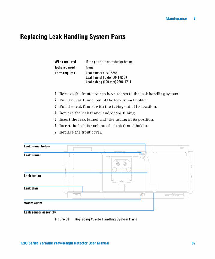
Replacing Leak Handling System Parts
1 Remove the front cover to have access to the leak handling system.
2 Pull the leak funnel out of the leak funnel holder.
3 Pull the leak funnel with the tubing out of its location.
4 Replace the leak funnel and/or the tubing.
5 Insert the leak funnel with the tubing in its position.
6 Insert the leak funnel into the leak funnel holder.
7 Replace the front cover.
When required If the parts are corroded or broken.
Tools required None
Parts required Leak funnel 5061-3356Leak funnel holder 5041-8389Leak tubing (120 mm) 0890-1711
Figure 33 Replacing Waste Handling System Parts
Waste outlet
Leak plan
Leak sensor assembly
Leak tubing
Leak funnel
Leak funnel holder
1200 Series Variable Wavelength Detector User Manual 97
8 Maintenance
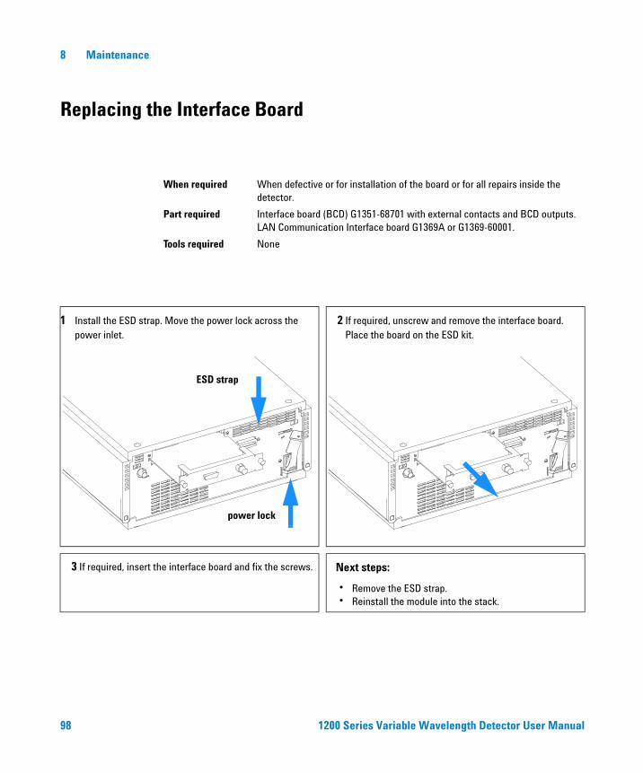
Replacing the Interface Board
When required When defective or for installation of the board or for all repairs inside the detector.
Part required Interface board (BCD) G1351-68701 with external contacts and BCD outputs.LAN Communication Interface board G1369A or G1369-60001.
Tools required None
1 Install the ESD strap. Move the power lock across the power inlet.
2 If required, unscrew and remove the interface board. Place the board on the ESD kit.
3 If required, insert the interface board and fix the screws. Next steps:
• Remove the ESD strap.• Reinstall the module into the stack.
ESD strap
power lock
98 1200 Series Variable Wavelength Detector User Manual

Maintenance 8
Replacing the Detector’s Firmware
The installation of older firmware might be necessary:
• to keep all systems on the same (validated) revision, or
• if third part control software requires a special version.
To upgrade/downgrade the detector’s firmware the following steps have to be performed:
1 Download the module’s firmware, the LAN/RS-232 FW Update Tool Version 2.00 or above and the documentation from the Agilent web
http://www.chem.agilent.com/scripts/cag_firmware.asp.
2 Load the firmware into the detector as described in the documentation.
When required If new version solves problems of currently installed version or after exchange of the detector main board (VWM) the version on board is older than previous installed one.
Tools required LAN/RS-232 Firmware Update Tool, orInstant Pilot G4208A or Control Module G1323B
Parts required Firmware, tools and documentation from Agilent web site
Preparations Read update documentation provided with the Firmware Update Tool.
NOTE The G1314C VWD-SL requires firmware revision A.06.02 or above (main and resident).
1200 Series Variable Wavelength Detector User Manual 99
8 Maintenance
Tests & Calibrations
The following tests are required after maintenance of lamps and flow cells:
• “Intensity Test" on page 102.
• “Wavelength Verification/Calibration" on page 104.
• “Holmium Oxide Test" on page 105.
100 1200 Series Variable Wavelength Detector User Manual

Maintenance 8
Intensity Test
The intensity test measures the intensity of the deuterium lamp over the full VWD wavelength range (190 – 600 nm). The test can be used to determine the performance of the lamp, and to check for dirty or contaminated flow cell windows. When the test is started, the gain is set to zero. To eliminate effects due to absorbing solvents, the test should be done with water in the flow cell. The shape of the intensity spectrum is primarily dependent on the lamp, grating, and diode characteristics. Therefore, intensity spectra will differ slightly between instruments. Figure 34 shows a typical intensity test spectrum.
Intensity Test Evaluation (Agilent ChemStation only)
The Agilent ChemStation evaluates three values automatically and displays the limits for each value, the average, the minimum and the maximum of all data points and passed or failed for each value.
Test Failed
Probable Causes
• Absorbing solvent in flow cell.
• Dirty or contaminated flow cell.
• Dirty or contaminated optical components (source lens, mirrors, grating).
• Old or non-Agilent lamp.
Suggested Actions
✔ Ensure the flow cell is filled with water.
✔ Repeat the test with the flow cell removed. If the test passes, exchange the flow cell windows.
✔ Clean/replace optical components.
✔ Exchange the lamp.
1200 Series Variable Wavelength Detector User Manual 101
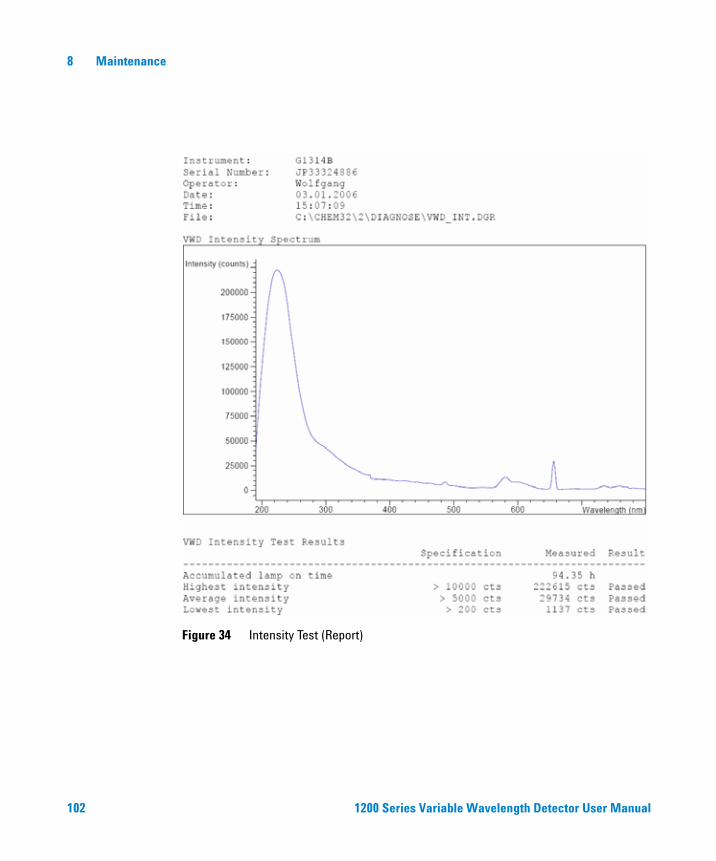
8 Maintenance
Figure 34 Intensity Test (Report)
102 1200 Series Variable Wavelength Detector User Manual
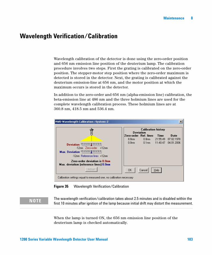
Maintenance 8
Wavelength Verification/Calibration
Wavelength calibration of the detector is done using the zero-order position and 656 nm emission line position of the deuterium lamp. The calibration procedure involves two steps. First the grating is calibrated on the zero-order position. The stepper-motor step position where the zero-order maximum is detected is stored in the detector. Next, the grating is calibrated against the deuterium emission-line at 656 nm, and the motor position at which the maximum occurs is stored in the detector.
In addition to the zero-order and 656 nm (alpha-emission line) calibration, the beta-emission line at 486 nm and the three holmium lines are used for the complete wavelength calibration process. These holmium lines are at 360.8 nm, 418.5 nm and 536.4 nm.
When the lamp is turned ON, the 656 nm emission line position of the deuterium lamp is checked automatically.
Figure 35 Wavelength Verification/Calibration
NOTE The wavelength verification/calibration takes about 2.5 minutes and is disabled within the first 10 minutes after ignition of the lamp because initial drift may distort the measurement.
1200 Series Variable Wavelength Detector User Manual 103
8 Maintenance
Holmium Oxide Test
This test verifies the calibration of the detector against the three wavelength maxima of the built-in holmium oxide filter. The test displays the difference between the expected and measured maxima. Figure 36 shows a holmium test spectrum.
The test uses the following holmium maxima:
• 360.8 nm
• 418.5 nm
• 536.4 nm
When to do the Test
• after recalibration,
• as part of the Operational Qualification/Performance Verification procedure, or
• after flow cell maintenance or repair.
Interpreting the Results
The test is passed successfully when all three wavelengths are within ± 1 nm of the expected value. This indicates the detector is calibrated correctly.
NOTE See also “Declaration of Conformity for HOX2 Filter" on page 129.
NOTE The test results are currently available on the Agilent ChemStation only.
ChemStation revisions below B.01.xx show a limit of ± 2 nm. It should read ± 1 nm. If the test shows a value greater than ± 1 nm, perform a recalibration.
104 1200 Series Variable Wavelength Detector User Manual
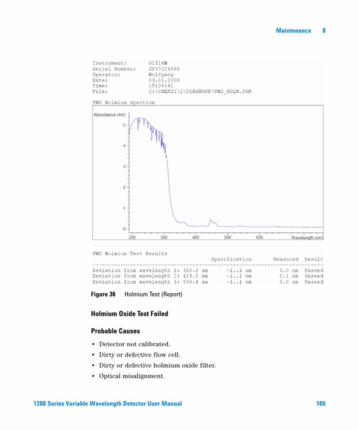
Maintenance 8
Holmium Oxide Test Failed
Probable Causes
• Detector not calibrated.
• Dirty or defective flow cell.
• Dirty or defective holmium oxide filter.
• Optical misalignment.
Figure 36 Holmium Test (Report)
1200 Series Variable Wavelength Detector User Manual 105

8 Maintenance
Suggested Actions
✔ Re-calibrate the detector.
✔ Repeat the test with the flow cell removed. If the test is OK, exchange the flow cell components.
✔ Run the holmium oxide filter test. If the test fails, exchange the filter assembly.
✔ Realign the optical components.
106 1200 Series Variable Wavelength Detector User Manual

Maintenance 8
1200 Series Variable Wavelength Detector User Manual 107

8 Maintenance
108 1200 Series Variable Wavelength Detector User Manual

Agilent 1200 Series Variable Wavelength DetectorUser Manual
9Parts and Materials for Maintenance
Overview of Maintenance Parts 110
Standard Flow Cell 111
Micro Flow Cell 112
Semi-micro Flow Cell 113
High Pressure Flow Cell 115
Cuvette Holder 116
Leak Parts 117
Accessory Kit 118
This chapter provides information on parts for maintenance.
109Agilent Technologies

9 Parts and Materials for Maintenance
Overview of Maintenance Parts
Table 15 Maintenance Parts
Item Description Part Number
Cable CAN assembly 0.5 m 5181-1516
Cable CAN assembly 1 m 5181-1519
Interface board BCD/External Contacts G1351-68701
LAN Communication Interface board G1369A orG1369-60001
Control Module G1323B (Note: The G1314C VWD-SL can be operated with a G1323B just in standard mode as G1314B - no higher data rate available) orInstant Pilot G4208A
G1323-67001
G4208-67001
Deuterium lamp G1314-60100
Standard flow cell, 10 mm 14 µl, additional flow cell parts, see page 111 G1314-60086
Micro flow cell, 5 mm 1 µl, additional flow cell parts, see page 112 G1314-60081
High pressure flow cell, 10 mm 14 µl, additional flow cell parts, see page 115 G1314-60082
Semi-micro flow cell, 6 mm 5 µl, additional flow cell parts, see page 113 G1314-60083
Cuvette Holder G1314-60200
Front cover 5065-9982
Leak handling parts see page 117
110 1200 Series Variable Wavelength Detector User Manual

Parts and Materials for Maintenance 9
Standard Flow Cell
Table 16 Standard Flow Cell Assembly
Item Description Part Number
Standard Flow Cell, 10 mm, 14 µl, 40 bar G1314-60086
1 Cell screw kit, quantity=2 G1314-65062
2 Conical spring kit, quantity=10 79853-29100
3 Ring #1 PEEK kit, quantity=2 G1314-65065
4 Gasket #1 (small hole), KAPTON, quantity=10 G1314-65063
5 Window quartz kit, quantity=2 79853-68742
6 Gasket #2 (large hole), KAPTON, quantity=10 G1314-65064
7 Ring #2 PEEK kit, quantity=2 G1314-65066
Figure 37 Standard Flow Cell
1 - Cell Screw2 - Conical Springs3 - Ring #1 PEEK4 - Gasket #1 (small hole)5 - Window Quartz6 - Gasket #2 (large hole)7 - Ring #2 PEEK
12
3
54
65
72
1
1200 Series Variable Wavelength Detector User Manual 111
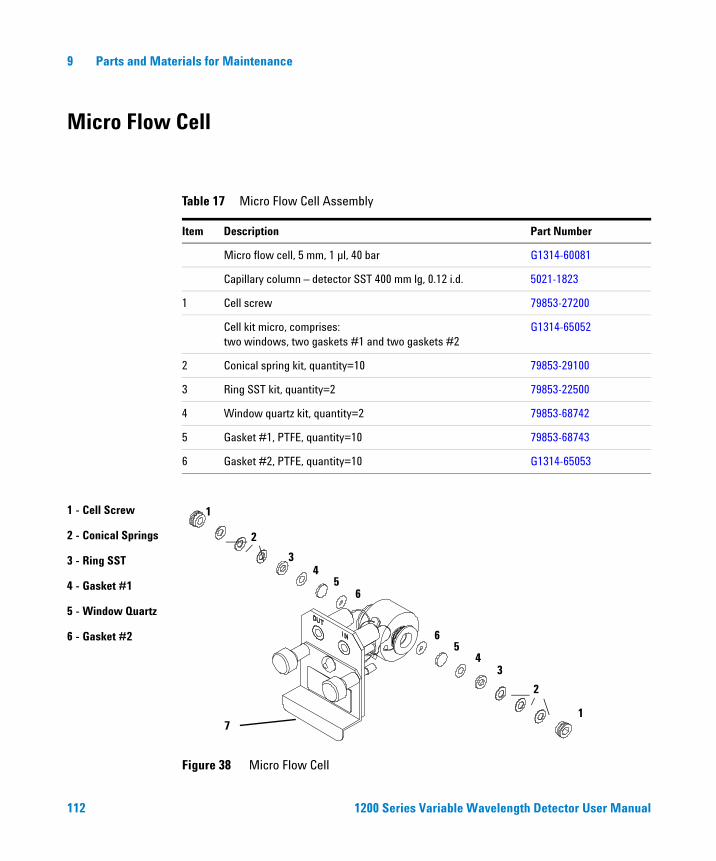
9 Parts and Materials for Maintenance
Micro Flow Cell
Table 17 Micro Flow Cell Assembly
Item Description Part Number
Micro flow cell, 5 mm, 1 µl, 40 bar G1314-60081
Capillary column – detector SST 400 mm lg, 0.12 i.d. 5021-1823
1 Cell screw 79853-27200
Cell kit micro, comprises:two windows, two gaskets #1 and two gaskets #2
G1314-65052
2 Conical spring kit, quantity=10 79853-29100
3 Ring SST kit, quantity=2 79853-22500
4 Window quartz kit, quantity=2 79853-68742
5 Gasket #1, PTFE, quantity=10 79853-68743
6 Gasket #2, PTFE, quantity=10 G1314-65053
Figure 38 Micro Flow Cell
1 - Cell Screw
2 - Conical Springs
3 - Ring SST
4 - Gasket #1
5 - Window Quartz
6 - Gasket #2
1
2
34
56
65
43
2
17
112 1200 Series Variable Wavelength Detector User Manual

Parts and Materials for Maintenance 9
Semi-micro Flow Cell
Table 18 Semi-micro Flow Cell Assembly
Item Description Part Number
Semi-micro flow cell assembly, 6 mm, 5 µl, 40 bar G1314-60083
1 Cell screw 79853-27200
Semi-micro cell kit, consisting of:two windows, two #1 standard gaskets, one #1 semi-micro gasket and one #2 semi-micro gasket.
G1314-65056
2 Conical springs, (pack of 10) 79853-29100
3 Ring SST, (pack of 2) 79853-22500
4 PTFE #1 standard gasket, (pack of 10) 79853-68743
5 Quartz window, (pack of 2) 79853-68742
6 Semi-micro #1 gasket, PTFE, (pack of 10) G1314-65057
7 Semi-micro #2 gasket, PTFE, (pack of 10) G1314-65058
Inlet capillary, 400 mm long, 0.12 mm i.d. 5021-1823
NOTE The semi-micro #1 and #2 gaskets (items 6 and 7) look very similar. Do not mix them up.
1200 Series Variable Wavelength Detector User Manual 113

9 Parts and Materials for Maintenance
Figure 39 Semi-micro Flow Cell
1 - Cell screw2 - Conical springs3 - Ring SST4 - Gasket #15 - Quartz window 6 - Semi-micro gasket #1 7 - Semi-micro gasket #2
1
2
34
57
65
43
2
1
114 1200 Series Variable Wavelength Detector User Manual

Parts and Materials for Maintenance 9
High Pressure Flow Cell
Table 19 High Pressure Flow Cell Assembly
Item Description Part Number
High pressure flow cell, 10 mm, 14 µl, 400 bar G1314-60082
Capillary column–detector SST 380 mm lg, 0.17 i.d. (one side not assembled)
G1315-87311
1 Cell screw 79853-27200
Cell kit Agilent, comprises:two windows, two KAPTON gaskets and two PEEK rings
G1314-65054
2 Ring PEEK kit, quantity=2 79853-68739
3 Window quartz kit, quantity=2 79853-68734
4 Gasket kit, KAPTON, quantity=10 G1314-65055
Figure 40 High Pressure Flow Cell
1 - Cell screw
2 - Ring PEEK
3 - Window quartz
4 - Gasket KAPTON
5 - Cell Cover
4
3
1
2
4
2
1
3
1200 Series Variable Wavelength Detector User Manual 115
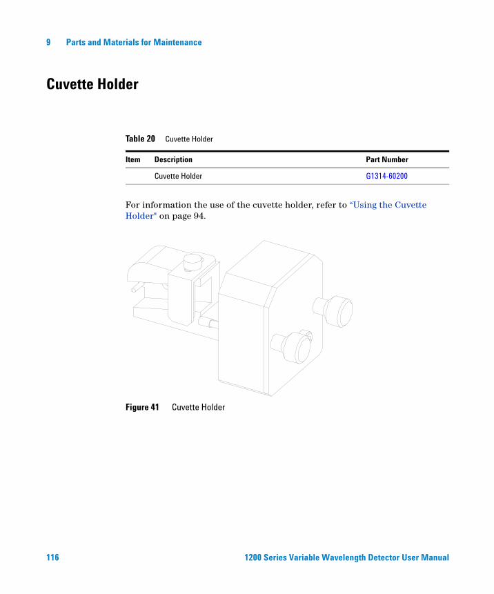
9 Parts and Materials for Maintenance
Cuvette Holder
For information the use of the cuvette holder, refer to “Using the Cuvette Holder" on page 94.
Table 20 Cuvette Holder
Item Description Part Number
Cuvette Holder G1314-60200
Figure 41 Cuvette Holder
116 1200 Series Variable Wavelength Detector User Manual

Parts and Materials for Maintenance 9
Leak Parts
Table 21 Leak Parts
Item Description Part Number
3 Leak funnel 5041-8388
4 Leak funnel holder 5041-8389
5 Clip 5041-8387
6 Corrugated tubing, 120 mm lg, re-order 5 m 5062-2463
7 Corrugated tubing, 1200 mm lg, re-order 5 m 5062-2463
Figure 42 Leak Parts
7
5
43
6
1200 Series Variable Wavelength Detector User Manual 117
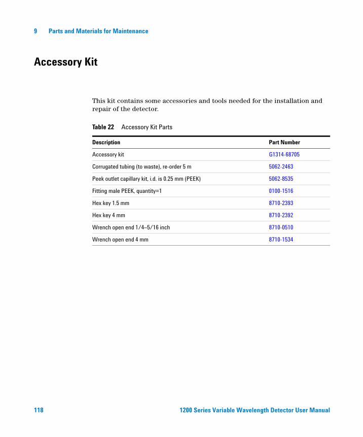
9 Parts and Materials for Maintenance
Accessory Kit
This kit contains some accessories and tools needed for the installation and repair of the detector.
Table 22 Accessory Kit Parts
Description Part Number
Accessory kit G1314-68705
Corrugated tubing (to waste), re-order 5 m 5062-2463
Peek outlet capillary kit, i.d. is 0.25 mm (PEEK) 5062-8535
Fitting male PEEK, quantity=1 0100-1516
Hex key 1.5 mm 8710-2393
Hex key 4 mm 8710-2392
Wrench open end 1/4–5/16 inch 8710-0510
Wrench open end 4 mm 8710-1534
118 1200 Series Variable Wavelength Detector User Manual
Agilent 1200 Series Variable Wavelength DetectorUser Manual
AAppendix
General Safety Information 120
Lithium Batteries Information 123
Radio Interference 124
Sound Emission 125
UV-Radiation 126
Solvent Information 127
Declaration of Conformity for HOX2 Filter 129
Agilent Technologies on Internet 130
This chapter provides addition information on safety, legal and web.
119Agilent Technologies

A Appendix
General Safety Information
The following general safety precautions must be observed during all phases of operation, service, and repair of this instrument. Failure to comply with these precautions or with specific warnings elsewhere in this manual violates safety standards of design, manufacture, and intended use of the instrument. Agilent Technologies assumes no liability for the customer’s failure to comply with these requirements.
General
This is a Safety Class I instrument (provided with terminal for protective earthing) and has been manufactured and tested according to international safety standards.
This instrument is designed and certified as a general purpose laboratory instrument for research and routine application only. It is not certified for in-vitro or medical applications.
Operation
Before applying power, comply with the installation section. Additionally the following must be observed.
Do not remove instrument covers when operating. Before the instrument is switched on, all protective earth terminals, extension cords, auto-transformers, and devices connected to it must be connected to a protective earth via a ground socket. Any interruption of the protective earth grounding will cause a potential shock hazard that could result in serious personal injury. Whenever it is likely that the protection has been impaired, the instrument must be made inoperative and be secured against any intended operation.
Make sure that only fuses with the required rated current and of the specified type (normal blow, time delay, and so on) are used for replacement. The use of repaired fuses and the short-circuiting of fuse holders must be avoided.
120 1200 Series Variable Wavelength Detector User Manual

Appendix A
Some adjustments described in the manual, are made with power supplied to the instrument, and protective covers removed. Energy available at many points may, if contacted, result in personal injury.
Any adjustment, maintenance, and repair of the opened instrument under voltage should be avoided as much as possible. When inevitable, this should be carried out by a skilled person who is aware of the hazard involved. Do not attempt internal service or adjustment unless another person, capable of rendering first aid and resuscitation, is present. Do not replace components with power cable connected.
Do not operate the instrument in the presence of flammable gases or fumes. Operation of any electrical instrument in such an environment constitutes a definite safety hazard.
Do not install substitute parts or make any unauthorized modification to the instrument.
Capacitors inside the instrument may still be charged, even though the instrument has been disconnected from its source of supply. Dangerous voltages, capable of causing serious personal injury, are present in this instrument. Use extreme caution when handling, testing and adjusting.
CAUTION The operator of this instrument is advised that if the equipment is used in a manner not specified in this manual, the protection provided by the equipment may be impaired.
1200 Series Variable Wavelength Detector User Manual 121

A Appendix
Safety Symbols
Table 23 shows safety symbols used on the instrument and in the manuals.
Table 23 Safety Symbols
Symbol Description
The apparatus is marked with this symbol when the user should refer to the instruction manual in order to protect the apparatus against damage.
Indicates dangerous voltages.
Indicates a protected ground terminal.
Indicates eye damage may result from directly viewing the light produced by the deuterium lamp used in this product.
!
WARNING A warning alerts you to situations that could cause physical injury or damage to the equipment. Do not proceed beyond a warning until you have fully understood and met the indicated conditions.
CAUTION A caution alerts you to situations that could cause a possible loss of data. Do not proceed beyond a caution until you have fully understood and met the indicated conditions.
122 1200 Series Variable Wavelength Detector User Manual

Appendix A
Lithium Batteries Information
WARNING Danger of explosion if battery is incorrectly replaced. Replace only with the same or equivalent type recommended by the equipment manufacturer. Lithium batteries may not be disposed-off into the domestic waste.
Transportation of discharged Lithium batteries through carriers regulated by IATA/ICAO, ADR, RID, IMDG is not allowed. Discharged Lithium batteries shall be disposed off locally according to national waste disposal regulations for batteries.
WARNING Lithium batteri - Eksplosionsfare ved fejlagtig håndtering. Udskiftning må kun ske med batteri af samme fabrikat og type. Lever det brugte batteri tilbage til leverandøren.
WARNING Lithiumbatteri - Eksplosionsfare. Ved udskiftning benyttes kun batteri som anbefalt av apparatfabrikanten. Brukt batteri returneres appararleverandoren.
NOTE Bij dit apparaat zijn batterijen geleverd. Wanneer deze leeg zijn, moet u ze niet weggooien maar inleveren als KCA.
1200 Series Variable Wavelength Detector User Manual 123
A Appendix
Radio Interference
Never use cables other than the ones supplied by Agilent Technologies to ensure proper functionality and compliance with safety or EMC regulations.
Test and Measurement
If test and measurement equipment is operated with equipment unscreened cables and/or used for measurements on open set-ups, the user has to assure that under operating conditions the radio interference limits are still met within the premises.
124 1200 Series Variable Wavelength Detector User Manual

Appendix A
Sound Emission
Manufacturer’s Declaration
This statement is provided to comply with the requirements of the German Sound Emission Directive of 18 January 1991.
This product has a sound pressure emission (at the operator position) < 70 dB.
• Sound Pressure Lp < 70 dB (A)
• At Operator Position
• Normal Operation
• According to ISO 7779:1988/EN 27779/1991 (Type Test)
1200 Series Variable Wavelength Detector User Manual 125

A Appendix
UV-Radiation
Emissions of ultraviolet radiation (200-315 nm) from this product is limited such that radiant exposure incident upon the unprotected skin or eye of operator or service personnel is limited to the following TLVs (Threshold Limit Values) according to the American Conference of Governmental Industrial Hygienists:
Typically the radiation values are much smaller than these limits:
Table 24 UV-Radiation Limits
Exposure/day Effective Irradiance
8 hours 0.1 µW/cm2
10 minutes 5.0 µW/cm2
Table 25 UV-Radiation Typical Values
Position Effective Irradiance
Lamp installed, 50-cm distance average 0.016 µW/cm2
Lamp installed, 50-cm distance maximum 0.14 µW/cm2
126 1200 Series Variable Wavelength Detector User Manual

Appendix A
Solvent Information
Observe the following recommendations on the use of solvents.
Flow Cell
Avoid the use of alkaline solutions (pH > 9.5) which can attack quartz and thus impair the optical properties of the flow cell.
Prevent any crystallization of buffer solutions. This will lead into a blockage/damage of the flow cell.
If the flow cell is transported while temperatures are below 5 degree C, it must be assured that the cell is filled with alcohol.
Aqueous solvents in the flow cell can built up algae. Therefore do not leave aqueous solvents sitting in the flow cell. Add small % of organic solvents (e.g. Acetonitrile or Methanol ~5%).
Solvents
Brown glass ware can avoid growth of algae.
Always filter solvents, small particles can permanently block the capillaries. Avoid the use of the following steel-corrosive solvents:
• Solutions of alkali halides and their respective acids (for example, lithium iodide, potassium chloride, and so on).
• High concentrations of inorganic acids like nitric acid, sulfuric acid especially at higher temperatures (replace, if your chromatography method allows, by phosphoric acid or phosphate buffer which are less corrosive against stainless steel).
• Halogenated solvents or mixtures which form radicals and/or acids, for example:
2CHCl3 + O2 → 2COCl2 + 2HCl
This reaction, in which stainless steel probably acts as a catalyst, occurs quickly with dried chloroform if the drying process removes the stabilizing alcohol.
1200 Series Variable Wavelength Detector User Manual 127
A Appendix
• Chromatographic grade ethers, which can contain peroxides (for example, THF, dioxane, di-isopropylether) such ethers should be filtered through dry aluminium oxide which adsorbs the peroxides.
• Solutions of organic acids (acetic acid, formic acid, and so on) in organic solvents. For example, a 1-% solution of acetic acid in methanol will attack steel.
• Solutions containing strong complexing agents (for example, EDTA, ethylene diamine tetra-acetic acid).
• Mixtures of carbon tetrachloride with 2-propanol or THF.
128 1200 Series Variable Wavelength Detector User Manual
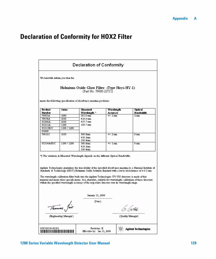
Appendix A
Declaration of Conformity for HOX2 Filter
1200 Series Variable Wavelength Detector User Manual 129
A Appendix
Agilent Technologies on Internet
For the latest information on products and services visit our worldwide web site on the Internet at:
http://www.agilent.com
Select “Products” - “Chemical Analysis”
It will provide also the latest firmware of the Agilent 1200 Series modules for download.
130 1200 Series Variable Wavelength Detector User Manual

Index
Index
Aabsorbance
Beer-Lambert, 67accessory kit (parts), 118Agilent
ChemStation, 45LC diagnostic software, 76on internet, 130
Agilent on internet, 130algea information, 127analog
output range, 55, 59output settings, 59
ASTMenvironmental conditions, 23reference and conditions, 26
attenuation, 50autobalance, 50automatic turn on, 55
Bband width 6.5 nm, 25battery
safety information, 123beam splitter, 14Beer-Lambert (law), 67bench space, 23boards
photodiode boards (ADC), 14
Ccable
connecting APG remote, 32connecting CAN, 32connecting GPIB, 32connecting LAN, 32connecting the analog, 34connecting the APG remote, 34connecting the CAN, 34connecting the ChemStation, 32connecting the LAN, 34connecting the power, 32, 34
CAN
connecting interface, 34cautions and warnings, 79chromatogram, 44configuration
stack, 30connector locations at rear, 34control module G1323B, 10, 75correction factors for flow cells, 68cutoff filter, 13cuvette holder, 94
Ddata rate, 62, 69declaration of conformity, 129delivery checklist, 28detection type, 25diagnostic
signals, 72dimensions, 24drift, 25, 47
initial, 52
Eelectrical connections
descriptions of, 15EMF (early maintenance feedback), 18enable analysis when lamp is off, 60entrance slit assembly, 13environment, 23error messages, 72ESD (electrostatic discharge) strap, 81exchange
interface board, 99
Ffeatures, 10
GLP, 26instrument layout, 17safety and maintenace, 26
firmwareupdates, 100
flow cell, 12choosing, 66
correction factors, 68cuvette holder (parts), 116high pressure (parts), 115micro (parts), 112path length, 68semimicro (parts), 113standard (parts), 111types and data, 12, 25
front of detector, 33
Ggrating
assembly, 14
Hholmium oxide
declaration of conformity, 129filter, 13
Iinformation
on cuvette holder, 94on lithium batteries, 123on radio interference, 124on solvents, 127on sound emission, 125on UV-radiation, 126
installationof flow connections, 36of module, 33
instant pilot, 75instrument layout, 17internet, 130introduction, 10
to optical system, 11isocratic test sample, 54
Llamp, 13
initial drift, 52intensity test, 102type, 25, 55
1200 Series Variable Wavelength Detector User Manual 131

Index
leakcorrecting, 97panels (parts), 117
linepower consumption, 24voltage and frequency, 24
linearity, 25, 26
Mmaintenance, 83
cleaning the instrument, 80correcting leaks, 97exchanging flow cell, 87exchanging interface board, 99exchanging lamps, 85exchanging leak handling system, 98for parts see ’parts for
maintenance’, 109introduction, 77overview, 84replacing firmware, 100simple repairs, 78standard flow cell, 90using the cuvette holder, 94using the ESD strap, 81
methoderror, 55load, 48
mirrorassemblies, 14
Nnegative absorbance, margins, 60noise, short term, 25
Oonline plot, 52online spectra, 56operating temperature, 24optical unit
beam splitter assembly, 14entrance slit assembly, 13filter, 13filter assembly, 13flow cell, 12grating assembly, 14
lamp, 13mirrors, 14photodiode assemblies, 14photodiode boards, 14source lens assembly, 13
optimizationdetector performance, 66of the system, 44
overviewoptical path, 11optical system, 11system overview, 11
Pparameters
detector, 49parts
and materials for maintenance, 109parts for maintenance
accessory kit, 118cuvette holder, 116high pressure flow cell, 115leak panels, 117micro flow cell, 112overview of maintenance parts, 110semimicro flow cell, 113standard flow cell, 111
peakwidthsettings, 50, 61, 69
performanceoptimization, 66specifications, 25
photodiodeassemblies, 14boards, 14
photometric accuracy, 68physical specifications, 24
humidity, 24line voltage and frequency, 24operating temperature, 24power consumption, 24safety information, 24weight and dimensions, 24
powerconsiderations, 22consumption, 24cords, 22
preparing the HPLC system, 45
Rradio interference, 124rear of detector, 34recalibration of wavelength, 72reference conditions, 26repairs
cleaning the instrument, 80introduction, 77of internal parts, 78overview of simple repairs, 84simple maintenance, 78simple repairs see ’maintenance’, 83using the ESD strap, 81
replacingfirmware, 100
response time, 62, 69running the sample, 54
Ssafety
class I instrument, 120general information, 120lithium batteries, 123symbols, 122
sample info, 53scan range / step, 60scanning, 57setting up an analysis, 40settings
analog output settings, 59peakwidth, 61
setup of detector, 49signal
plot, 51polarity, 60
signalsadditional (diagnostics), 50diagnostic, 72
site requirements, 22bench space, 23environment, 23power considerations, 22power cords, 22
solvent information, 127sound emission, 125source lens assembly, 13special setpoints, 50, 60
132 1200 Series Variable Wavelength Detector User Manual

Index
special settings, 55specifications
performance, 25physical, 24
spectraonline, 56
stable baseline, 47stack configuration, 30, 32
rear view, 32standards, 24status indicators, 72, 74stop time, post time, 50stop-flow condition, 56
Ttest functions, 72tests
holmium oxide, holmium oxide test, 105
intensity of lamp, 102wavelength calibration, 104
time table, 50troubleshooting
Agilent LC diagnostic software, 76diagnostic signals, 72error messages, 72overview, 72status indicator, 74status indicators, 72, 73test functions, 72user interfaces, 75
turn on,automatic, 55
Uunpacking, 28user interfaces
ChemStation, Control Module, Instant Pilot, 75
usingadditional signals (diagnostics), 50Agilent ChemStation, 45analog output range, 55analog output settings, 59at power on, 55attenuation, 50autobalance, 50automatic turn on, 55
data rate, 62detector parameters, 49drift, 47EMF, 18enable analysis when lamp is off, 60error method, 55isocratic test sample, 54lamp type, 55load method, 48negative absorbance, margins, 60online plot, 52online spectra, 56peakwidth setting, 50peakwidth settings, 61preparing the HPLC system, 45priming and purging the system, 40requirements and conditions, 42response time, 62running the sample, 54sample info, 53scan range / step, 60scanning, 57setting up an analysis, 40setup of detector, 49signal plot, 51signal polarity, 60special setpoints, 50, 60special settings, 55stable baseline, 47stop and post time, 50stop-flow condition, 56the cuvette holder, 94the detector, 39time table, 50turn on, 46typical chromatogram, 44warm up, 47zero offset, 50
UV-radiation, 126
Wwarm up, 47warnings and cautions, 79wavelength
accuracy, 25calibration, 104range 190-600 nm, 25recalibration, 72
weight, 24
Zzero offset, 50
1200 Series Variable Wavelength Detector User Manual 133

Index
134 1200 Series Variable Wavelength Detector User Manual


© Agilent Technologies 2006
Printed in Germany 02/06
*G1314-90010**G1314-90010*G1314-90010
www.agilent.com
Agilent Technologies
In This Book
This manual contains the technical reference information about the Agilent 1200 Series variable wavelength detector.
The manual describes the following:
• introcduction and specifications,
• installation,
• using and optimizing,
• troubleshooting overview,
• maintenance,
• parts identification,
• safety and related information.