fukushima daiichi nuclear power station unit 2 … daiichi nuclear power station unit 2 primary...
TRANSCRIPT
Fukushima Daiichi Nuclear Power Station Unit 2 Primary Containment Vessel Internal Investigation ResultsFebruary 1, 2018
Tokyo Electric Power Company Holdings, Inc.

1
【Investigation Plan】: The area underneath the platform, where fuel debrismay exist, was checked.
Scope of this PCV internal investigation
RPV
Containment vessel penetration used for this investigation (X-
6 penetration)
Primary containment vessel (PCV)
Control rod drive mechanism (CRD) replacement rails
Pedestal opening Pedestal
Platform
Control rod drive mechanism (CRD)
housing
Scope of this investigation
Worker access opening
Approx.7.2m
Containment vessel penetration used for
previous investigations (X-53
penetration)
Sub-floor
1. Primary Containment Vessel Internal Investigation Overview
Fallen grating ①Fallen
grating ②(no hole)
2
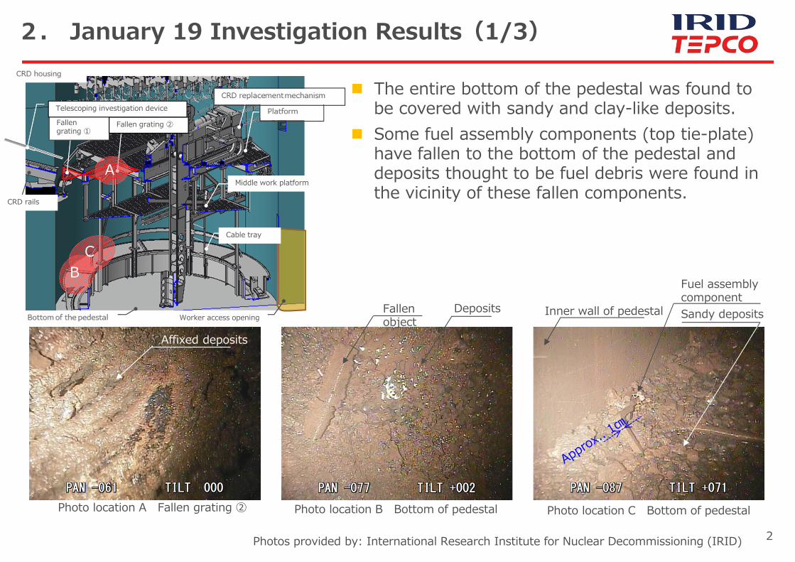
2. January 19 Investigation Results(1/3)
Photos provided by: International Research Institute for Nuclear Decommissioning (IRID)
Fuel assembly component
Photo location A Fallen grating ② Photo location B Bottom of pedestal Photo location C Bottom of pedestal
Fallen object
Inner wall of pedestal
Affixed deposits
The entire bottom of the pedestal was found to be covered with sandy and clay-like deposits.
Some fuel assembly components (top tie-plate) have fallen to the bottom of the pedestal and deposits thought to be fuel debris were found in the vicinity of these fallen components.
Sandy deposits Deposits
A
BC
Worker access opening
Cable tray
Middle work platform
Fallen grating ①
Fallen grating ②
Telescoping investigation device
CRD rails

3
2. January 19 Investigation Results (2/3)
Photos provided by: International Research Institute for Nuclear Decommissioning (IRID)
Photo location D Surface ofinner wall of pedestal
Photo location E CRD replacement mechanism
Photo location F CRD housing support
Near the worker access opening (estimated)
Inner wall of pedestal
CRD replacement mechanism
CRD housing support fitting support barCRD housing support fitting hanger rod
No significant damage was see on the inner wall of pedestal
No significant damage was seen to existing structures inside the pedestal (CRD replacement mechanism)
The CRD housing supports were found to be in the same condition as was seen during the January~February 2017 investigations.
PIP cable
DE
F
Worker access opening
Telescoping investigation device
Fallen grating ①
Fallen grating ②
Cable tray
Middle work platform
CRD rails
4
Worker access opening
Bottom of pedestal
垂直断面図
Telescoping investigation device
CRD housing
CRD rails
Middle work platform
Cable tray
CRD replacement mechanism
Platform
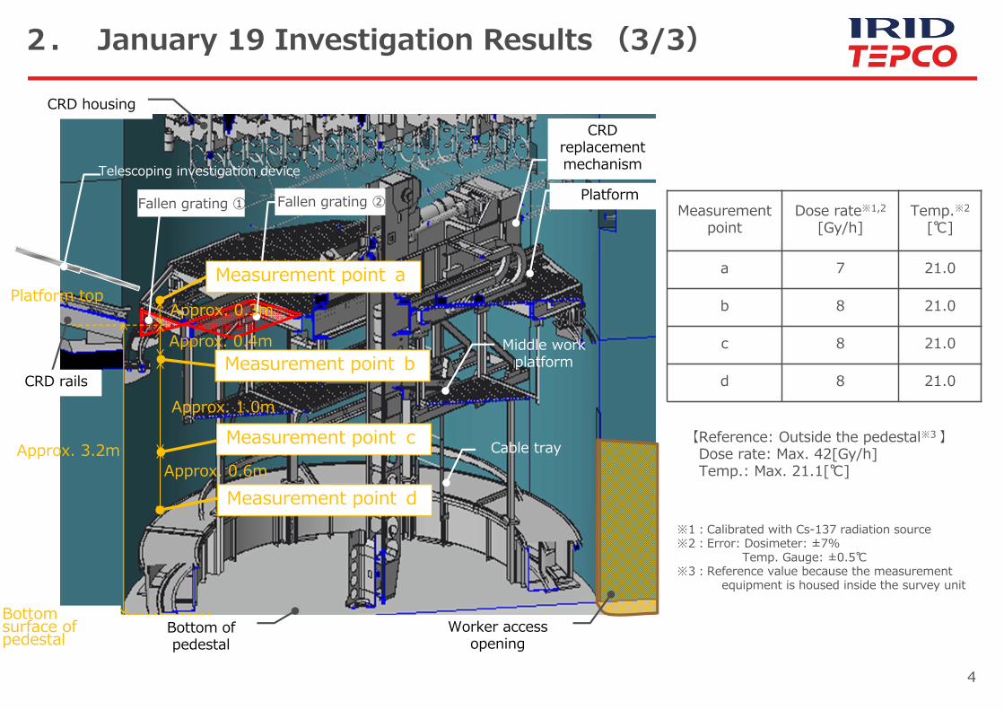
2. January 19 Investigation Results (3/3)
Measurement point a
Measurement point b
Measurement point c
Measurement point d
Approx. 0.3m
Approx. 0.4m
Approx. 1.0m
Approx. 0.6m
Platform top
Bottom surface of pedestal
Approx. 3.2m
Measurement point
Dose rate※1,2
[Gy/h]Temp.※2
[℃]
a 7 21.0
b 8 21.0
c 8 21.0
d 8 21.0
【Reference: Outside the pedestal※3 】Dose rate: Max. 42[Gy/h]Temp.: Max. 21.1[℃]
※1:Calibrated with Cs-137 radiation source※2:Error: Dosimeter: ±7%
Temp. Gauge: ±0.5℃※3:Reference value because the measurement
equipment is housed inside the survey unit
Fallen grating ① Fallen grating ②

5
【 Investigation Results Summary 】 The entire bottom of the pedestal was found to be covered with sandy
and clay-like deposits. Some fuel assembly components have fallen to the bottom of the
pedestal and deposits thought to be fuel debris were found in the vicinity of these fallen components.
The CRD housing supports were found to be in the same condition as was seen during the January~February 2017 investigations and no significant damage was seen.
Dose and temperature were approximately the same regardless of the height at which measurements were taken. And, dose rates tended to be higher outside the pedestal than inside.
The investigation was completed while keeping worker exposure doses under planned limits.
No significant fluctuations were seen in data from monitoring posts or dust monitors neither prior to, nor after, the investigation.
【Plans going forward】 The images taken during this investigation will be analyzed
3. Summary

6
Worker access opening
Bottom of pedestal
垂直断面図
Telescoping investigation device
CRD housing
Fallen grating ① Fallen grating②(no holes)
CRD rails
No holes
Middle work platform
Cable tray
CRD replacement mechanism
Platform
Reference: PCV Internal investigation location
Area that the investigation unit accessed during this investigation (tentative)

7
Reference: Fuel assembly component (top tie-plate) overview
Simple drawing of fuel assembly component (top tie-plate)
Simple drawing of fuel assembly
Top tie-plate
Fuel rodsWater channel
Spacer
Channel box
Bottom tie-plate
(Ties fuel rods together)

8
Reference: Reference dose rate measurement locations
2017 investigation measurement location (estimated from camera screen static)
2017 investigation measurement location (calculated using integral dosimeter
Measurement location (this investigation)
Reference measurement location (this investigation) ※1
※1:Reference value because the measurement equipment is housed inside the survey unit
Approximate position of guide pipe (during insertion/withdrawal)
Approximate position of guide pipe (when telescoping pipe is extended)
Less than approx. 10Gy/h
Scaffolding Approx. 70Gy/h
Approx. 80Gy/h
Approx. 70Gy/h
Less than approx. 10Gy/h
PCV
X-6 penetration
CRD rails
Pedestal
Platform
Lifting beam
Approx. 0.7m
Approx. 0.9m
Approx. 6.8m19Gy/h
7Gy/h(Measurement
point a)
28Gy/h42Gy/h
7Gy/h(Fallen grating ① top)
7Gy/h(Fallen grating ② top)
CRD housing
15Gy/h
Approx. 2.6m Approx. 0.9m Approx. 1.2m
Approx. 0.4m
20Gy/h

9
Camera
Cable feed mechanism
Survey unit
Light
Prior to lowering
When lowered
Overhead camera
Dosimeter/Temperature gauge
Foreign contaminant/snagging prevention skirt
Pan axis
Tilt axis
Overview of end of investigation device
Reference: Dosimeter/Temperature Gauge Mounting Location
Photos provided by: International Research Institute for Nuclear Decommissioning (IRID)
Dosimeter/Temperature gauge (when housed)
10
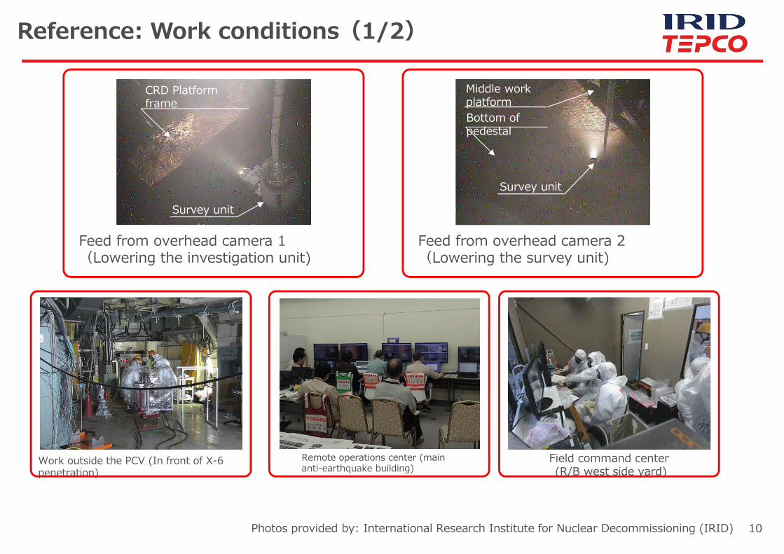
Field command center(R/B west side yard)
Remote operations center (main anti-earthquake building)
Work outside the PCV (In front of X-6 penetration)
Feed from overhead camera 1(Lowering the investigation unit)
Feed from overhead camera 2(Lowering the survey unit)
Reference: Work conditions(1/2)
Photos provided by: International Research Institute for Nuclear Decommissioning (IRID)
CRD Platform frame
Bottom of pedestal
Middle work platform
Survey unit
Survey unit

11
Platform
Substitute shield Isolation
valve Pedestal
Extendable pipe Guide pipe
PCVCable drum
End bending control unit
PCV penetration (X-6 penetration
seal)
Reference: Work conditions (2/2)
Platform
Substitute shield Isolation
valve Pedestal
Guide pipe
PCV
End bending control unit
PCV penetration (X-6 penetration
seal)
R/B
R/BField command
center
Field command
center
Survey unit is operated remotely from the remote operations center
During installation of the investigation device
During the investigation
Field workers insert and withdraw the investigation device, install cable drum and extend the extendable pipe from in front of the X-6 penetration
During remote operation of the survey unit, field workers retreat to the field command center on the west side of the R/B where radiation levels are lower to avoid unnecessary exposure.
The survey unit is lowered/raised, the cameras and lights operated and doses/temperature measurements taken remotely from the remote operations center
※Other structures not related to the PCV internal investigation have been omitted
・Total exposure dose (including preparations~investigation~clean-up)Planned:0.31[person/Sv] Actual: 0.22[person/Sv](as of 1/31)
・Actual individual maximum dose: 1.68[mSv/day](Planned dose:3[mSv/day])

12
There was no impact on the surrounding environment from radiation during internal investigation of the Unit 2 primary containment vessel conducted on January 19.
During the investigation a boundary was constructed to prevent the gases from inside the containment vessel from leaking into the external environment.
No significant fluctuations in data from monitoring posts and dust monitors were seen neither prior to, nor after, the investigation.
Data from monitoring posts and dust monitors near site boundaries can be found on our website.
URL:http://www.tepco.co.jp/en/nu/fukushima-np/f1/index-e.htmlhttp://www.tepco.co.jp/en/nu/fukushima-np/f1/dustmonitor/index-e.html
Reference: Environmental Impact(1/2)
(Reference) Website Excerpt
*Radiation levels include contributions from radiation sources other than the inside of the primary containment vessel.

13
During the investigation, plant parameters were continuously monitored and no significant fluctuations were seen in the temperature of the primary containment vessel neither prior to, nor after, the investigation. There were also no changes in the cold shut down status of the reactor.
Primary containment vessel internal temperature data can be viewed on our website.URL:http://www.tepco.co.jp/en/nu/fukushima-np/f1/plantdata/unit2/pcv_index-e.html
Reference: Environmental Impact(2/2)
(Reference) Website Excerpt