*free software & technical support prevention mining exploration pile monitoring dam wall...
TRANSCRIPT
DT85GM Series 3 Data LoggerDesigned especially for remote monitoring
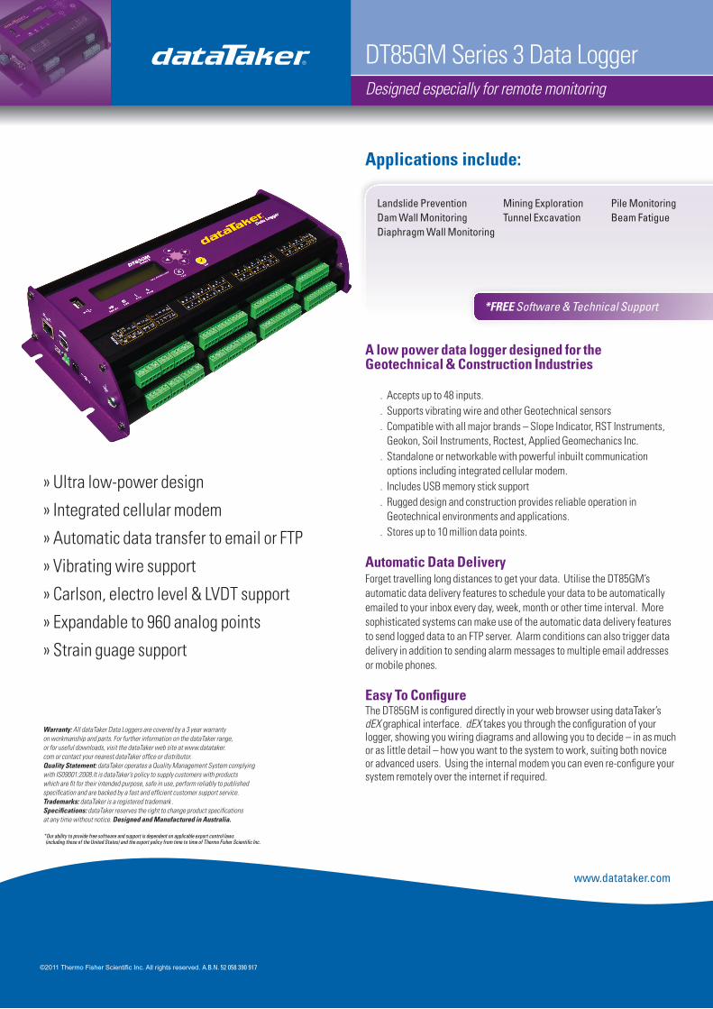
A low power data logger designed for the Geotechnical & Construction Industries
Accepts up to 48 inputs. .Supports vibrating wire and other Geotechnical sensors .Compatible with all major brands – Slope Indicator, RST Instruments, .Geokon, Soil Instruments, Roctest, Applied Geomechanics Inc.Standalone or networkable with powerful inbuilt communication .options including integrated cellular modem.Includes USB memory stick support .
. Rugged design and construction provides reliable operation in Geotechnical environments and applications.Stores up to 10 million data points. .
Automatic Data DeliveryForget travelling long distances to get your data. Utilise the DT85GM’s automatic data delivery features to schedule your data to be automatically emailed to your inbox every day, week, month or other time interval. More sophisticated systems can make use of the automatic data delivery features to send logged data to an FTP server. Alarm conditions can also trigger data delivery in addition to sending alarm messages to multiple email addresses or mobile phones.
Easy To ConfigureThe DT85GM is configured directly in your web browser using dataTaker’s dEX graphical interface. dEX takes you through the configuration of your logger, showing you wiring diagrams and allowing you to decide – in as much or as little detail – how you want to the system to work, suiting both novice or advanced users. Using the internal modem you can even re-configure your system remotely over the internet if required.
Applications include:
Landslide Prevention Mining Exploration Pile MonitoringDam Wall Monitoring Tunnel Excavation Beam FatigueDiaphragm Wall Monitoring
*FREE Software & Technical Support
» Ultra low-power design
» Integrated cellular modem
» Automatic data transfer to email or FTP
» Vibrating wire support
» Carlson, electro level & LVDT support
» Expandable to 960 analog points
» Strain guage support
©2011 Thermo Fisher Scientific Inc. All rights reserved. A.B.N. 52 058 390 917
Warranty: All dataTaker Data Loggers are covered by a 3 year warranty on workmanship and parts. For further information on the dataTaker range, or for useful downloads, visit the dataTaker web site at www.datataker.com or contact your nearest dataTaker office or distributor.Quality Statement: dataTaker operates a Quality Management System complying with IS09001:2008.It is dataTaker’s policy to supply customers with products which are fit for their intended purpose, safe in use, perform reliably to published specification and are backed by a fast and efficient customer support service.Trademarks: dataTaker is a registered trademark .Specifications: dataTaker reserves the right to change product specifications at any time without notice. Designed and Manufactured in Australia.
*Our ability to provide free software and support is dependent on applicable export control laws (including those of the United States) and the export policy from time to time of Thermo Fisher Scientific Inc.
www.datataker.com
dEX Logger Software
» Built-in software - no application to install
» Runs directly from your web browser
» Accessible by Ethernet, USB connection or integrated modem
» Intuitive graphical interface
» Easy-to-use configuration editor
» Access live and historical data
» View data as charts, mimics and tables
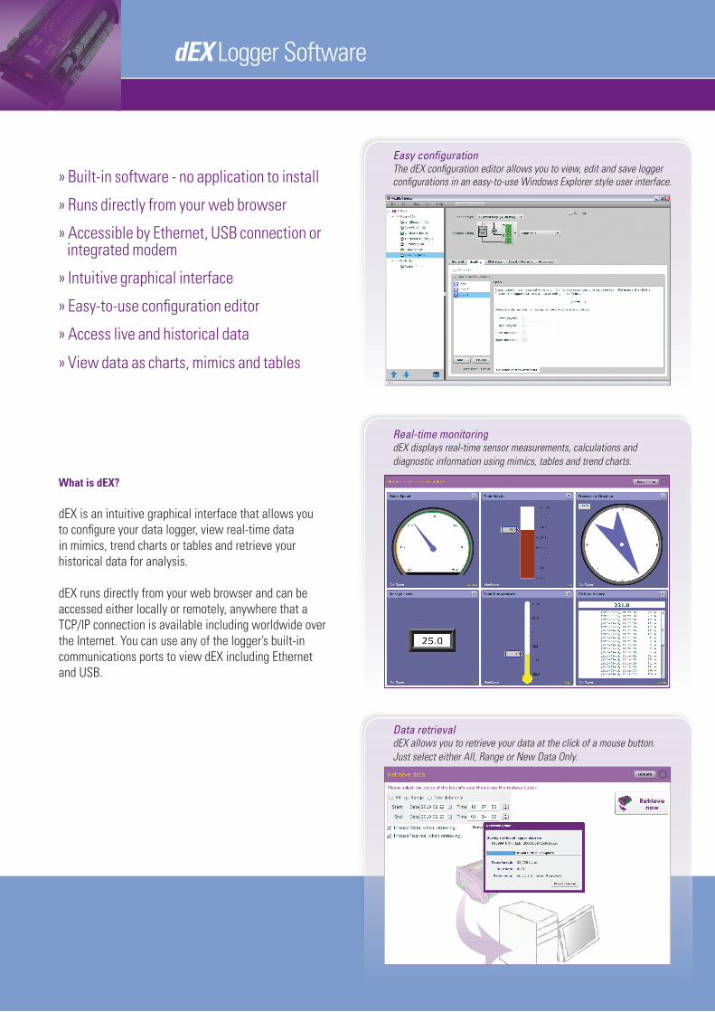
Easy configuration The dEX configuration editor allows you to view, edit and save logger configurations in an easy-to-use Windows Explorer style user interface.
What is dEX? dEX is an intuitive graphical interface that allows you to configure your data logger, view real-time data in mimics, trend charts or tables and retrieve your historical data for analysis.
dEX runs directly from your web browser and can be accessed either locally or remotely, anywhere that a TCP/IP connection is available including worldwide over the Internet. You can use any of the logger’s built-in communications ports to view dEX including Ethernet and USB.
Real-time monitoring dEX displays real-time sensor measurements, calculations and diagnostic information using mimics, tables and trend charts.
Data retrieval dEX allows you to retrieve your data at the click of a mouse button. Just select either All, Range or New Data Only.
dEX Logger Software
The difference is dEX!
Browser-based solution dEX comes pre-installed on every logger in the DT80 range. The software loads in your web browser so there is no need to install cumbersome applications on your computer. Being browser-based, dEX is cross-platform and will work on all major operating systems including Windows, Mac and Linux.
Data that is compatible with your applicatons Logged data is ready to import into common spreadsheet and data processing applications such as Excel for further analysis and reporting. Data can be saved to your computer in comma separated (.CSV) format or our proprietary binary (.DBD) format.
Command windowThe command window provides a terminal interface which allows the built-in command language of the logger to be used. Macro buttons allow common commands to be sent on a button press.
Configuration editorThe configuration editor allows you to view, edit and save logger configurations in an easy-to-use Windows Explorer style user interface. Tree view of configuration allows definition of measurement schedules and measurements. Wiring diagrams show available wiring configurations for each sensor type. Configuration can be stored and retrieved on either the logger or a local computer.
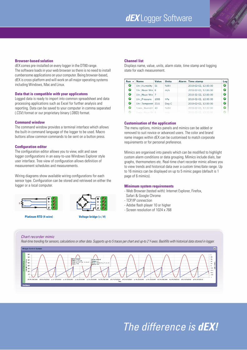
Platinum RTD (4 wire) Voltage bridge (+ / #)
Chart recorder mimic Real-time trending for sensors, calculations or other data. Supports up-to 5 traces per chart and up-to 2 Y-axes. Backfills with historical data stored in logger.
Channel list Displays name, value, units, alarm state, time stamp and logging state for each measurement.
Customisation of the application The menu options, mimics panels and mimics can be added or removed to suit novice or advanced users. The color and brand name images within dEX can be customised to match corporate requirements or for personal preference.
Mimics are organised into panels which can be modified to highlight custom alarm conditions or data grouping. Mimics include dials, bar graphs, thermometers etc. Real-time chart recorder mimic allows you to view trends and historical data over a custom time/date range. Up to 16 mimics can be displayed on up to 5 mimic pages (default is 1 page of 6 mimics).
Minimum system requirements- Web Browser (tested with): Internet Explorer, Firefox, Safari & Google Chrome- TCP/IP connection- Adobe flash player 10 or higher- Screen resolution of 1024 x 768

Technical Specifications
Analog Channels16 analog input channels (expandable to 320*) Each channel is independent and supports: one isolated 3-wire or 4-wire input, or two isolated 2-wire inputs, or three common referenced 2-wire inputs. The following maximums apply: Two wire with common reference terminal: 48 (expandable to 960)* Two wire isolated: 32 (expandable to 640)* Three and four wire isolated: 16 (expandable to 320)**Expansion requires optional CEM20.Fundamental Input RangesThe fundamental inputs that the DT85GM can measure are voltage, current, resistance and frequency. All other measurements are derived from these.
Auto-ranging is supported over 3 ranges. Accuracy
Accuracy table above is % of reading ±0.01% of full scale.
SamplingIntegrates over 50/60Hz line period for accuracy and noise rejectionMaximum sample speed: 25HzEffective resolution: 18 bitsLinearity: 0.01%Common mode rejection: >90dBLine series mode rejection: >35dBInputsInter-Channel Isolation: 100V (relay switching)Analog Section Isolation: 100V (opto-isolated)Input impedance: >100MΩ, 100KΩ (30v range) Common mode range: ±3.5V or ±30V on 30V rangeSensor Excitation (Supply)Analog channels: selectable 250μA or 2.5mA precision current source, 4.5V voltage source, or switched external supply. General Purpose: Switchable 12V regulated supply for powering sensors & accessories (max 150mA). Switchable 5V regulated supply for powering analog sensors (max 25mA).
Analog SensorsSupports a wide range of sensors including, but not limited to, those listed below. A wide range of sensor scaling and linearising facilities including polynomials, expressions and functions. ThermocouplesTypes: B, C, D, E, G, J, K, N, R, S, TCalibration standard: ITS-90RTDsMaterials supported: Pt, Ni, CuResistance range: 10Ω to 10KΩVibrating WireFrequency range: 500 to 5kHzCoil resistance: 50 to 200ΩSimulation method: single pulse pluckThermistorsTypes: YSI 400xx Series, other types*Resistance range: <10kΩ*** Other thermistor types are supported by thermistor scaling and calculated channels.
**Resistance range can be increased with the use of a parallel resistor.
Monolithic Temperature SensorsTypes supported: LM34 - 60, AD590, 592, TMPxx, LM135, 235, 335Strain Gauge and Bridge SensorsConfigurations: ¼ , ½ & full bridgeExcitation: voltage or current4-20mA Current LoopInternal 100Ω shunt or external shunt resistor
Digital ChannelsDigital Input/Outputs8 bi-directional channelsInput Type: 8 logic level (max 20/30V)Output Type: 4 with open drain FET(max: 30V, 100mA), 4 with logic output.Relay Output1 latching relay, contacts (max: 30Vdc, 1A)
Counter ChannelsLow Speed Counters8 counters shared with digital inputs.Low speed counters do not function in sleep mode.Size: 32 bit Max count rate: 10 HzDedicated Counter Inputs7 high speed inputs or 3 phase encoder (quadrature) inputsSize: 32 bitMax count rate: 100 kHzInput type: 5 logic level inputs (max ±30V), and 2 programmable inputs as either logic level inputs or sensitive inputs (10mV) for magnetic pick-ups (max ±10V)
Serial ChannelsSDI-124 SDI-12 input shared with digital channels Each channel supports up to 10 SDI-12 sensors.
Calculated ChannelsCombine values from analog, digital and serial sensorsusing expressions involving variables and functions.Functions: An extensive range of Arithmetic, Trigonometric, Relational, Logical and Statistical functions are available.
AlarmsCondition: high, low, within range and outside rangeDelay: optional time period for alarm responseActions: set digital outputs, transmit message via SMS or email, execute any dataTaker command.
Scheduling of Data AcquisitionNumber of schedules: 11Schedule rates: 10ms to days
Data Storage Internal StoreCapacity: 128MB = approx 10,000,000 data pointsRemovable USB store device(optional accessory)Types: compatible with USB 1.1 or USB 2.0 drives,Capacity: approx. 90,000 data points per megabyte
Communication InterfacesEthernet PortInterface: 10BaseT (10Mbps)Protocol: TCP/IPUSB PortInterface: USB 1.1Protocol: TCP/IP or ASCII commandSerial Sensor PortInterface: RS232, RS422m, RS485Speed: 300 to 115,200 baudFlow Control: Hardware (RTS/CTS),Software (XON/XOFF), NoneProtocols: Modbus, Serial Sensor
Network (TCP/IP) ServicesUses Ethernet port or integrated modemCommand InterfaceAccess the ASCII command interface via TCP/IPWeb ServerAccess dEX to view data or configure the logger. Define custom dynamic web pages.Download data in CSV or DBD format. Command interface window. Define mimic displays.FTP ServerAccess logged data from any FTP client or web browser.FTP ClientAutomatically upload logged data direct to an FTP server.
Modbus Server (Slave) Access current data and status from any Modbus clientModbus Client (Master) Read/write data from Modbus sensors and devices including PLCs, dataTaker dataloggers, modbus displays.Email ClientEmail data or alarms directly from the logger. DDNS ClientBrowse to the logger over the Internet using Dynamic DNS.
SystemDisplay and KeypadType: LCD, 2 line by 16 characters, backlight.Display Functions: channel data, alarms, system status.Keypad: 6 keys for scrolling and function execution.Status LEDs: 4 for sample, disk, attention and power.Firmware UpgradeVia: Ethernet, USB or USB diskReal Time ClockNormal resolution: 200μsAccuracy: ±1 min/year (0°C to 40°C),±4 min/year (-40°C to 70°C)Power SupplyExternal voltage range: 10 to 30VdcPeak Power: 12W Average Power Consumption (typical)Using 12Vdc external power source.Values within brackets represent the additional power required by the modem to push data daily to an FTP server.
Inbuilt ModemFeaturesAlarms: Send email or SMS messagesData: Send data to an email address or FTP serverRemote access: Connect to dEX or Command interfaceSIM interface: SIM Socket (1.8V/3V)Networks and FrequenciesUSA Only:Interfaces: EDGE, GPRS, GSM, CSDAll other places:Interfaces: EDGE, GPRS, GSM, WCDMA, HSUPA, HSDPAFrequencies:EDGE/GPRS/GSM: 850/900/1800/1900 MHzWCDMA/HSUPA/HSDPA: 850/1900/2100 MHz
Physical and EnvironmentConstruction: Powder coated steel andanodized aluminum.Dimensions: 300 x 137 x 65mmWeight: 2.5kg (5kg shipping)Temperature range: -30°C to 70°C *Humidity: 85% RH, non-condensing*reduced LCD operation outside range -15°C to 50°C
Accessories IncludedResource CD: includes software and user manual.Comms cable: USB cableLine adaptor: 110/240Vac to 15Vdc, 800mAAntenna with 2m cable
Optional AccessoriesA range of accessories are available. For full technical specifications download the user’s manual from our website www.datataker.com.
Full Scale Res olution Full Scale Resolution ±30 mVdc 0.25 μV 100 Ω 1.5 mΩ ±300 mVdc 2.5 μV 1000 Ω 15 mΩ ±3 Vdc 25 μV 10,000 Ω 150.00 mΩ ±30 Vdc 250 μV 100 Hz 0.0002 % ±0.3 mA 2.5 nA 10 kHz 0.0002 % ±3 mA 25 nA ±30 mA 250 nA
1 analog sample 6 analog samplesSchedule Rate Average Power (mW) Average Power (mW) 1 sec 540 (9) 840 (27)5 sec 250 (3) 330 (7)30 sec 50 (2) 65 (2)1 min 30 (2) 40 (2)5 min 15 (2) 15 (2)30 min 10 (2) 10 (2)1 hrs 10 (2) 10 (2)
Your local distributor
TS-0082-F1
Measurement at ... 5°C to 40°C – 45°C to 70°C
DC Voltage 0.1% 0.35% DC Current 0.15% 0.45% DC Resistance 0.1% 0.35% Frequency 0.1% 0.25%