bard fusion-tectm wall-mount tm free ... - adarac.co.il
TRANSCRIPT

Form No. S3564-618Supersedes S3564-418APage 1 of 36
LC 6000 Controller
R-410A
Dual Capacity: System fluctuates between two cooling capacities. The WR Series High Sensible system operates in part load or full load cooling, based upon need and peak efficiency.
Reverse Airflow: Peak performance low side air discharge directs the cooler air used for electronics and equipment cooling at floor level where it is needed. The heat from the shelter is pulled back into the FUSION-TEC from ceiling level to be exhausted to the outside, or integrated into the mechanical cooling system.
DAC Free Cooling Unit: All units are designed to optimize any free cooling outdoor air opportunities. The FUSION-TEC features positive seal dampers to eliminate unwanted air migration. Peak operation is constantly monitored and deviations result in an alarm. (Free cooling may be disabled via software when needed.) As a safety design, an air quality switch has been integrated into the system to keep dirt and debris out of the building .
Logic Board: System control panels are equipped with PLC Logic Boards that allow multiple unit operation (up to 14 units and 3 zones) with a single controller. Unit connection to the LC6000 controller is accomplished with 2 wire shielded cable daisy chain with drain (ground).
Advanced Unit Diagnostics: Whether connected to the TEC-EYETM diagnostic tool, or just viewed from the shelter control, the system PLC Logic Board is able to display stored alarms and easy to read diagnostic information.
Orphan Mode: System is designed to run independently if communication to the LC6000 controller is lost, meaning that cooling can be provided even if the controller or wiring fails.
Airflow Switch: All systems feature an airflow switch to monitor blower operation. Settings are field adjustable with alarm signal.
Dirty Filter Switch: All systems include an airflow switch to monitor pressure drop across the unit filter. This will indicate when a filter change is needed. Settings are field adjustable with alarm signal. An indicator light is located on the outside of the FUSION-TEC that illuminates when the filter needs replaced.
High Pressure Transducer: A high pressure transducer is used for advanced diagnostic features including an alarm signal when condenser coil cleaning is needed.
Low Pressure Transducer: A pressure transducer is used for advanced diagnostic features and indication of refrigerant loss. Combined with other sensors, the FUSION-TEC will constantly display superheat readings.
High Efficiency Indoor Blower: Using the latest technology DEC Star® and HEB fan designs, the FUSION-TEC achieves peak CFM airflow rates with the lowest energy usage possible.
High Efficiency Outdoor Fan Motor: The FUSION-TEC uses a high efficiency ECM fan system to provide air through the condenser coil. By varying the fan speed, the system is able to provide the airflow needed at high and low outdoor temperature conditions.
Security Features: By selecting the BardGuardTM option, electronic security features allow the system to sense coil and copper theft, and features multiple alarm options. An in-shelter disarm button allows authorized personnel to service the system.
Enhanced Grilles: The FUSION-TEC reverse airflow design uses enhanced indoor supply and return grilles for maximized airflow and inreased cooling dispersion in the structure.
Bard FUSION-TECTM
Reverse Airflow Unit
Bard is anISO 9001:2008
Certified Manufacturer
BARD FUSION-TECTM WALL-MOUNTTM Free Cooling DAC Economizer and Air Conditioner
The FUSION-TECTM has been designed specifically to optimize Free Direct Ambient Cooling (DAC) opportunities. By implementing a reverse-airflow design, productive outdoor air for free cooling is brought into the system from the lower portion of the chassis. The heat in the shelter is exhausted out of the top of the chassis which completely eliminates any possibility of recirculating hot exhaust into the cool air entryway. When outdoor air is not productive for free cooling, the FUSION-TEC system has a fully flexible mechanical cooling operation that operates at an IPLV of up to 17.0, and also satisfies the D.O.E.'s future 11.0 EER efficiency requirements.
Bard High Sensible Cooling SystemsWR36 Series 12.5 EER 2 to 3 Ton
WR58 Series 11.0 EER 3.5 to 5 Ton
Engineered Features

Form No. S3564-618Supersedes S3564-418APage 2 of 36
Unit Nomenclature
WR 58 A P A 0Z E P X X X X
MAXIMUM TOTAL CAPACITY 36 - 3 Ton 2 Stage Step Capicity 58 – 5 Ton 2 Stage Step Capacity
UNIT SERIES
CONTROL LOGIC AND CLIMATE OPTIONSP – Programmable Logic Board
VOLTS & PHASE A – 230/208/60/1B – 230/208/60/3
REVISIONA – Revision Level
ELECTRIC HEAT “0Z” 0kw with Circuit Breaker ''01'' 1.5kw with Circuit Breaker “05” 5kw with Circuit Breaker ''MZ'' 0kw with Circuit Breaker and Inverter Ready ''M1'' 1.5kw with Circuit Breaker and Inverter Ready ''M5'' 5kw with Circuit Breaker and Inverter Ready
VENT PACKAGEE – Factory-Installed Economizer (All Units)
FILTERP – MERV8 Disposable Pleated Filter
COLOR AND CABINET FINISHX – Beige Baked Enamel Finish 1 – White Baked Enamel Finish4 – Buckeye Gray Baked Enamel Finish5 – Desert Brown Baked Enamel Finish8 – Dark Bronze Baked Enamel Finish
PLACEHOLDERX – Future Use
COIL AND UNIT COATING OPTIONSX – Copper/Aluminum Evaporator Coil, Copper/Aluminum Condenser Coil1 – CoatedEvaporator Coil2 - Coated Condenser Coil3 – Coated Evaporator Coil, Coated Condenser Coil
ACCESSORIES AND CONTROLS OPTIONSX – Standard accessories including airflow sensor, dirty filter sensor, pressure transducers, crankcase heaterS – All standard accessories plus Bard GuardTM security features and security frameNote: Must order (1) BG1000 security interface for 1 to 4 units on the shelter.

Form No. S3564-618Supersedes S3564-418APage 3 of 36
Specifications WR36APA WR36APB
Performance*
3 Ton Full Load Total Cooling Capacity, BTUH 36,600 BTUH 36,600 BTUH
3 Ton Full Load EER 12.5 EER 12.5 EER
3 Ton Full Load CFM 1200 CFM 1200 CFM
2 Ton Part Load Total Cooling Capacity, BTUH 25,400 BTUH 25,400 BTUH
2 Ton Part Load EER 12.6 EER 12.6 EER
2 Ton Part Load CFM 950 CFM 950 CFM
IPLV (Integrated Part Load Value) 17.0 17.0
Rated Voltage 230/208 Volt 1 Phase 230/208 Volt 3 Phase
Compressor
Operating Voltage Range 197V to 253V 197V to 253V
Rated Load Amps 11.7/13.2 8.7/9.9
Branch Circuit Selection Current Amps 15.6 11.6
Locked Rotor Amps 83 73
Compressor Type 2 Stage Scroll 2 Stage Scroll
Condenser Fan Motor Speeds and Type Variable ECM Variable ECM
Condenser Fan and Motor
Condenser Fan Motor Horsepower 1/3 HP 1/3 HP
Condenser Fan Motor Amps 3.5 3.5
Condenser Fan Motor Min. – Max. RPM 100 – 1200 RPM 100 – 1200 RPM
Condenser Fan Diameter/Rotation 24” CCW 24” CCW
Condenser Fan CFM 2600 CFM Max. 2600 CFM Max.
Blower Motor and Indoor Airflow
Blower Motor Speeds and Type Variable ECM Variable ECM
Blower Motor Horsepower 1/3 HP 1/3 HP
Blower Motor Amps 2.5 A 2.5 A
Blower Motor Max. RPM 1200 RPM 1200 RPM
3 Ton Indoor Blower CFM @ Estimated Static Pressure inch W. C. (Rated, wet coil)
1200 CFM @ 0.0 E.S.P. 1200 CFM @ 0.0 E.S.P.
2 Ton Indoor Blower CFM @ Estimated Static Pressure inch W. C. (Rated, wet coil)
950 CFM @ 0.0 E.S.P. 950 CFM @ 0.0 E.S.P.
Filter Size – Number of filters 20 x 30 x 2 – 2 filters 20 x 30 x 2 – 2 filters
Filter Rating (Disposable Filter) MERV8 MERV8
FUSION-TECTM WR36 Unit Specifications
*Performance data given at AHRI rating conditions.

Form No. S3564-618Supersedes S3564-418APage 4 of 36
Specifications WR36APA WR36APB
Refrigeration System
Refrigeration Flow Control Device Electronic Expansion Valve Electronic Expansion Valve
High Pressure Sensor 0-5V Analog Transducer 0-5V Analog Transducer
Low Pressure Sensor 0-5V Analog Transducer 0-5V Analog Transducer
High Pressure Safety Switch Non-Adjustable NC Switch Non-Adjustable NC Switch
R410 Refrigerant Charge 102 oz. 102 oz.
Air Pressure and Temperature Sensors
Dirty Filter Indicator Switch Adjustable Pressure Switch Adjustable Pressure Switch
Blower Airflow Indicator Switch Adjustable Pressure Switch Adjustable Pressure Switch
Outdoor Air Sensor 10K Analog Sensor 10K Analog Sensor
Return Air Sensor 10K Analog Sensor 10K Analog Sensor
Supply Air Sensor 10K Analog Sensor 10K Analog Sensor
Economizer Specifications
Damper Motor 24VDC, Modulating (0-10V) 24VDC, Modulating (0-10V)
Damper Blade Switch Magnetic NO/NC Switch Magnetic NO/NC Switch
Outdoor Air Quality Sensor Adjustable Optical Sensor Adjustable Optical Sensor
Unit Weight Specifications
Estimated Unit Weight 510 lbs. 510 lbs.
Estimated Unit Shipping Weight 545 lbs. 545 lbs.
WR36 Unit Specifications (continued)

Form No. S3564-618Supersedes S3564-418APage 5 of 36
Specifications WR58APA WR58APB
Performance*
5 Ton Full Load Total Cooling Capacity, BTUH 58,000 BTUH 58,000 BTUH
5 Ton Full Load EER 11.0 EER 11.0 EER
5 Ton Full Load CFM 1800 CFM 1800 CFM
3.5 Ton Part Load Total Cooling Capacity, BTUH 42,000 BTUH 42,000 BTUH
3.5 Ton Part Load EER 11.3 EER 11.3 EER
3.5 Ton Part Load CFM 1400 CFM 1400 CFM
IPLV (Integrated Part Load Value) 15.7 15.7
Rated Voltage 230/208 Volt 1 Phase 230/208 Volt 3 Phase
Compressor
Operating Voltage Range 197V to 253V 197V to 253V
Rated Load Amps 20.4/23.0 12.4/14.0
Branch Circuit Selection Current Amps 27.1 16.5
Locked Rotor Amps 152.9 110
Compressor Type 2 Stage Scroll 2 Stage Scroll
Condenser Fan Motor Speeds and Type Variable ECM Variable ECM
Condenser Fan and Motor
Condenser Fan Motor Horsepower ½ HP ½ HP
Condenser Fan Motor Amps 4.3 4.3
Condenser Fan Motor Min. – Max. RPM 100 – 1200 RPM 100 – 1200 RPM
Condenser Fan Diameter/Rotation 24” CCW 24” CCW
Condenser Fan CFM 3300 CFM Max. 3300 CFM Max.
Blower Motor and Indoor Airflow
Blower Motor Speeds and Type Variable ECM Variable ECM
Blower Motor Horsepower ¾ HP ¾ HP
Blower Motor Amps 3.6 A 3.6 A
Blower Motor Max. RPM 1200 RPM 1200 RPM
5 Ton Indoor Blower CFM @ Estimated Static Pressure inch W. C. (Rated, wet coil)
1800 CFM @ 0.0 E.S.P. 1800 CFM @ 0.0 E.S.P.
3.5 Ton Indoor Blower CFM @ Estimated Static Pressure inch W. C. (Rated, wet coil)
1400 CFM @ 0.0 E.S.P. 1400 CFM @ 0.0 E.S.P.
Filter Size – Number of filters 20 x 30 x 2 – 2 filters 20 x 30 x 2 – 2 filters
Filter Rating (Disposable Filter) MERV8 MERV8
*Performance data given at AHRI rating conditions.
FUSION-TECTM WR58 Unit Specifications

Form No. S3564-618Supersedes S3564-418APage 6 of 36
Specifications WR58APA WR58APB
Refrigeration System
Refrigeration Flow Control Device Electronic Expansion Valve Electronic Expansion Valve
High Pressure Sensor 0-5V Analog Transducer 0-5V Analog Transducer
Low Pressure Sensor 0-5V Analog Transducer 0-5V Analog Transducer
High Pressure Safety Switch Non-Adjustable NC Switch Non-Adjustable NC Switch
R410 Refrigerant Charge 147 oz. 147 oz.
Air Pressure and Temperature Sensors
Dirty Filter Indicator Switch Adjustable Pressure Switch Adjustable Pressure Switch
Blower Airflow Indicator Switch Adjustable Pressure Switch Adjustable Pressure Switch
Outdoor Air Sensor 10K Analog Sensor 10K Analog Sensor
Return Air Sensor 10K Analog Sensor 10K Analog Sensor
Supply Air Sensor 10K Analog Sensor 10K Analog Sensor
Economizer Specifications
Damper Motor 24VDC, Modulating (0-10V) 24VDC, Modulating (0-10V)
Damper Blade Switch Magnetic NO/NC Switch Magnetic NO/NC Switch
Outdoor Air Quality Sensor Adjustable Optical Sensor Adjustable Optical Sensor
Unit Weight Specifications
Estimated Unit Weight 547 lbs. 547 lbs.
Estimated Unit Shipping Weight 580 lbs. 580 lbs.
WR58 Unit Specifications (continued)

Form No. S3564-618Supersedes S3564-418APage 7 of 36
Product Design Features
Counterflow WR Series in the Standard Wall Mount FootprintThe FUSION-TECTM WR series counterflow unit uses the advantages of having a high supply opening to draw warm air from the ceiling level, and discharge cooler air where it is needed the most, at equipment and floor level. This is done using the standard wall mount footprint that has been used for years in the shelter and equipment cooling industry and requires minimal or no wall modifications to replace existing wall mount cooling equipment. This is accomplished by reversing the airflow through the existing wall openings.
An Energy Saving DAC Economizer with Mechanical CoolingBy design, the Bard FUSION-TECTM WR Series counterflow unit has a built-in free cooling DAC economizer with separated intake and exhaust air paths. Using separate cold air intake and warm room air exhaust openings dramatically reduces the recirculation effect of room air being discharged from the unit and drawn back into the fresh air intake. This makes economizer operation as efficient as possible and allows for proper intake airflow temperature measurement.
MECHANICAL COOLING ECONOMIZER MODE

Form No. S3564-618Supersedes S3564-418APage 8 of 36
Unit Options
Cabinet Finish OptionsAll unit models are available in Beige, White, Buckeye Gray, Desert Brown and Dark Bronze.
Evaporator and Condenser Coil Coating OptionsAll models utilize a copper/aluminum evaporator and condenser coil. An additional corrosion resistant AeroMarine coating may be ordered for the evaporator coil, condenser coil or both evaporator and condenser coils.
Aluminum Fin (standard evaporator)
AeroMarine Fin (optional coil coating)
X = BEIGE 5 = DESERT BROWN1 = WHITE
8 = DARK BRONZE
4 = BUCKEYE GRAY

Form No. S3564-618Supersedes S3564-418APage 9 of 36
Control Options
Control Module Code
Field-Installed Part #
Fits Models Listed Description
X N/A All Models Standard control module package. It contains the following:• Logic Control Board• Electronic Expansion Valve• High Pressure Transducer• Low Pressure Transducer• High Pressure Safety Switch• Dirty Filter Pressure Switch• Indoor Blower Operation Switch• Return Air Temperature Sensor• Supply Air Temperature Sensor• Outdoor Temperature and Humidity Sensor• Compressor Control Module• Economizer Intake Air Quality Sensor• Compressor Crankcase Heater• Phase Monitor (3 phase models only)
S* N/A All Models
Security control module package. It contains the standard options listed above and the following:• Heavy Duty Security Frame with Easy Service Access• Panel Monitoring Devices• System Pressure Loss Switch• Speaker for Audible Alarm• Indoor Control Box with Arm and Disarm
N/A SK-118208/230-6D-1 60 Units Only
Hard start kit includes the following:• Start Relay• Run Capacitor
* "S" Control module requires purchase of the BG1000 control box. (1) BG1000 box required per shelter for 1-4 units.

Form No. S3564-618Supersedes S3564-418APage 10 of 36
WR Series Standard Components
Programmable Logic BoardEach unit uses a programmable logic board located in the unit control panel to communicate with the LC controller. By using a 2-wire connection, alarm functionality and unit operational commands are communicated. If communication is lost, the unit is able to run by using the logic in the unit controller in orphan mode.
Power Supply Specifications:
24Vac/Vdc +10%/-15% 50/60 HzMax power input: 28 VAInsulation between power supply and instrument:• Mod. 24Vac: reinforced ensured by the use of external safety
(class 2) transformer (mandatory)External fuse: 3.15 AT (mandatory)Minimum section of wires of all other connectors: 0.5mm2
Product Specifications:Program memory (FLASH): 128MBData memory: 16MB/8MBInternal clock precision: 100 ppmBattery type: Lithium button battery (removable), BR2032, 3 VdcBattery lifetime characteristics of removable battery; Min. 8 years in normal operating conditions.
User Interface:Type: all the pGD terminals with telephone connector J10, th-Tune single unit controller with connector J11/J12/J13
Operating Conditions:Storage: -40T70 °C, 90% rH non-condensingOperating: -40T60 °C, 90% rH non-condensing
Other Specifications:
Environmental pollution degree: 3Index of protection: IP00Class according to protection against electric shock: to be incorporated into Class 1 and/or Class 11 appliancesPTI of the insulating materials PCB: PTI 250'insulation material: PTI 175Period of stress across the insulating parts: longType of action: 1C; 1Y for SSR versionsType of disconnection or micro interruption: micro interruptioncategory of resistance to heat and fire: Category D (UL94 - VO)Immunity against voltage surges: Category IIIRated impulse voltage: 4000V;Temperature for Ball Pressure Test: 125 °C
Communication Lines Available:• 1 shielded RJ45 Ethernet line. To the Ethernet port only one circuit
type SELV CIRCUIT can be connectionsMaximum Ethernet port connection cable length: 100M CAT-5 STP
Wall-Mount Unit Control Board
Dirty Filter Switch
+ Communication Wire- Communication Wire
24VAC GND24VAC Hot
24VAC +Y TO Compressor CCM
24VAC +Stage 1 HeatStage 1 Heat
Blower Relay24VAC +Ground
2-10 VDC To Damper Actuator
Analog GroundEvap. Temp Sensor
24 VDC To Outdoor Air Sensor
Outdoor Humidity Sensor
Return Air Temp SensorOutdoor Air Temp Sensor
Mixed Air Temp Sensor
Digital GroundDamper Blade Switch
Low Pressure SwitchComp. Alarm Relay
MIS-3869
Smoke
Damper Blade Switch

Form No. S3564-618Supersedes S3564-418APage 11 of 36
DEC Star® Indoor Airflow SystemDEC Star is the first product to bring together a high efficiency blower (HEB) housing, axial flux (no shaft) BLAC motor, and variable speed ECM technology into one innovative assembly. The DEC Star blower system removes the motor from the blower inlet, eliminating restriction and improving system efficiency.
*Used on WR58 units only. WR36 units use high efficiency HEB design.
Specifications
• High efficiency blower (HEB) housing and impeller driven by axial flux BLAC motor with full featured sinusoidal EON motor control technology
• 10" diameter wheel
• Two patents issued on the unique geometry blower. Other patents pending on the Halo motor system.
• Operating speed range of 250 – 1400 rpm
• 16-pin thermostat and PWM input to control
• Variable speed, constant torque/constant airflow ECM
• 120/240/277 and 120/240 VAC single-phase input, 50/60Hz
• UL and cUL recognized system
Electronic Expansion Valve (EEV)The valves are certified in accordance with the main national and international standards. Precise control is guaranteed by electronic controllers, designed especially to optimize management of air conditioning and refrigeration systems, with special focus on energy saving. In addition, highly precise control is also assured by the special shape of the movable elements, guaranteeing flow with an equal percentage characteristic; the stroke length, achieved by using stainless steel ball bearings; and the use of high precision mechanical components.
Specifications
• Power supply voltage 12V
• Drive frequency 50 Hz
• Phase resistance (25°C/77°F) 40 Ohm ± 10%
• Index of protection IP67
• Step angle 7.5 °
• Linear advance/step 0.02 mm (0.001 inches)
• Complete closing steps 500
• Control steps 480
WR Series Standard Components
Form No. S3564-618Supersedes S3564-418APage 12 of 36
Copeland UltraTech CompressorThe Copeland Scroll UltraTech compressor offers a better means of powering air conditioning systems. Building on established scroll technology, the Copeland Scroll UltraTech compressor provides superior humidity control, greater efficiency and quieter operation, providing unsurpassed reliability and performance along with increased comfort and reduced energy bills.
Modulating compressors provide precise temperature control, lower humidity and greater energy efficiency in comparison to fixed capacity compressors. The Copeland Scroll UltraTech compressor modulates between two capacity settings, 67% and 100%. Two internal bypass ports enable the compressor to run at 67% part-load capacity during times when only part-load cooling is needed. When demand increases, the modulation ring is activated, sealing the bypass ports and instantly shifting capacity to 100%. Running for longer periods at part-load capacity (67%) lowers the humidity inside the building and allows the HVAC system to operate more quietly. With the redesigned Copeland Scroll UltraTech compressor, the VA load is reduced to an expected range of 2-5 VA.
EC Outdoor Fan MotorThe EC outdoor fan motor maintains its high efficiency across a wide operating range. The result is a significant reduction in energy use when the motor is run at reduced speeds.
Specifications
• ECM Technology
• Enclosed motor housing
• Efficiencies up to 80%
• Variable speed, constant torque, brushless DC motor
• Single-phase input, 50/60Hz
• Designed for direct-drive fan applications
• Operating speed range of 200-1800 RPM
• NEMA 48-frame
• cURus recognized component
• Single shaft with integrated control module
Dirty Filter SwitchAll unit models utilize an adjustable dirty filter pressure switch to indicate when the filter needs to be changed. The dirty filter switch measures the pressure difference on both sides of the filter through tubing routed to the blower and vent areas of the unit. When pressure increases to a pre-set measurement in the switch, an alarm signal is sent to the unit programmable logic board, then to the LC6000 controller. The controller energizes a set of normally open contacts. A LED light is also installed on the exterior cabinet surface to indicate a filter change is required.
WR Series Standard Components

Form No. S3564-618Supersedes S3564-418APage 13 of 36
Filter Replacement LightA light is provided on the exterior of the unit that illuminates when the unit filter needs to be replaced. The light is located on the front left side of the cabinet. When the alarm signal for a dirty filter is reset through the LC6000 series controller, the light will no longer be illuminated.
Indoor Blower Operation Pressure SwitchAll unit models will utilize an indoor blower operation switch to indicate when blower airflow is not adequate for unit operation due to a failed evaporator blower motor or other mechanical airflow issue. The switch measures the pressure difference on both sides of the blower partition through tubing routed to the blower inlet and outlet areas of the unit. When pressure decreases below a pre-set measurement in the switch, an alarm signal is sent to the unit programmable logic board, then to the LC6000 series controller. The controller energizes a set of normally open contacts.
Compressor Control ModuleA low voltage monitoring device is used to monitor power and indicate a low incoming voltage situation caused by inadequate shore power or generator operation. The monitoring device protects the unit against compressor contactor “chatter” and reverse compressor rotation during these situations.
Return Air Temperature SensorAll unit models have a return air temperature sensor installed for operation in “orphan” mode. The return air temperature sensor is also used for indoor temperature averaging with the use of the LC6000 series controller. The return air sensor is located in the upper part of the return opening in such a way that it is exposed to the entering airstream. Information is received by the unit logic control board using a 10K resistance signal. An alarm will be sent to the LC6000 series controller if the return air temperature sensor is disconnected.
Supply Air Temperature SensorAll unit models use a supply air temperature sensor. By monitoring the air temperature leaving the supply opening, the unit logic control board is able to monitor the air entering the shelter. Information is received by the unit logic control board using a 10K resistance signal. An alarm will be sent to the LC controller if the supply air temperature sensor is disconnected.
WR Series Standard Components

Form No. S3564-618Supersedes S3564-418APage 14 of 36
Outdoor Air Temperature and Humidity SensorAll unit models use a outdoor air temperature and humidity sensor. Using the sensor, the unit logic control board is able to monitor the outdoor air temperature, humidity and dew point. When conditions are acceptable for bringing in cooler outdoor air, the unit logic control board will allow economizer operation. The unit software can be set to operate economizer in Dry Bulb, Humidity %RH or dew point. An alarm will be sent to the LC6000 series controller if the supply air temperature sensor is disconnected.
Compressor Crankcase Heater All unit models have a crankcase heater installed as standard. The crankcase heater is a belly band style heater encircling the base section of the compressor housing. When the unit is not in operation, the crankcase heater is a precautionary measure to prevent compressor oil migration, deter oil and refrigeration from mixing and avoid refrigerant condensation. Care must be used when servicing the unit to avoid being burned by the belly band attached to the compressor base. Always disconnect power when servicing this area of the unit.
Economizer Air Intake Quality Dust SensorAll unit models include a dust sensor to monitor the outdoor air quality entering the economizer damper area. When conditions are unacceptable due to particulates in the air including farm field debris, highway dust and dirt, or other particulates, the economizer is disabled.
The sensor monitors dust density by using an optical system The optical portion of the sensor uses a light-emitting diode and light detector. The sensor is shipped pre-set, but may be adjusted for less or more sensitivity.
High Pressure TransducerAll unit models have a high side pressure transducer. The transducer will be used for system monitoring of high side system pressures. This information will be used to indicate when outdoor coil cleaning is necessary based on outdoor conditions and system pressures. When high pressure increases beyond a pre-set measurement when compared to outdoor temperature stored in the unit programmable logic board, an alarm signal is sent from the unit programmable logic board to the LC6000 series controller. The controller energizes a set of normally open contacts to indicate abnormal high system pressure. The high pressure transducer also controls the outdoor condenser fan and motor to increase outdoor airflow during high outdoor ambient conditions.
WR Series Standard Components

Form No. S3564-618Supersedes S3564-418APage 15 of 36
Low Pressure Transducer
All unit models have a low side pressure transducer installed on the suction line between the evaporator coil and compressor. The transducer is used for system monitoring of low side system pressures. This information is used to indicate a loss of system refrigerant. When low pressure drops below a pre-set measurement stored in the unit programmable logic board, an alarm signal is sent from the unit programmable logic board to the LC6000 series controller. The controller energizes a set of normally open contacts to indicate abnormal low system pressure. When a loss of charge is measured, the LC6000 series controller energizes a set of normally open contacts to indicate refrigerant loss and that the unit needs to be serviced. The low pressure transducer is also used for operation of the eletronic expansion valve (EEV). Superheat is displayed at the unit using the TEC-EYE diagnostic tool.
High Pressure Safety SwitchAll unit models have a high side pressure switch as a safety device. This device is connected to a safety rated set of contacts, and operates if high system pressures reach an unacceptable level. When activated, the unit will shut down compressor operation immediately. After a predetermined time, the unit will attempt to restart. If the switch is activated during the restart, compressor operation will lockout, and an alarm signal will be sent to the LC6000 series controller. This is a safety device that disables unit operation at a high refrigerant pressure. It is also used to protect unit components including the electronic expansion valve and compressor. Never disable the high pressure safety switch. Activation of the switch normally indicates the unit needs to be serviced.
Field-Installed Hard Start Kit SK-118 (Optional)All single phase models have a hard start kit available for field installation. The hard start kit may be used to provide additional torque for compressor startup. A relay is provided to energize a start capacitor during the initial starting of the compressor. When the starting winding voltage increases to a set value in the relay, the start capacitor is de-energized.
WR Series Standard Components

Form No. S3564-618Supersedes S3564-418APage 16 of 36
WR36 and WR58 Models
WR Series Unit Dimensions – Shelter Top and Side View
17.0
17.0
17.0
17.0
76.0
15.9
30.1
9.9
13.0
43.0
41.9
44.0
29.9
3.9
15.1
31.2
21.7
29.1
3.6
29.8
1.5
.4TY
P.
29.9
39.7
10.9
2.0 3.0
Con
dens
er A
ir Inta
ke
Ven
t Air I
ntake
Cond
ense
r air e
nters
the up
per f
ront
secti
on of
the
Open
ing
Retu
rn O
penin
g
Supp
ly
Acce
ssSe
rvice
Por
t
Acce
ssFil
ter
2.
Acce
ssSe
ction
Acce
ssCi
rcuit B
reak
er
Cond
ense
r
Acce
ssan
d Blow
erEv
apor
ator
Acce
ssSe
ction
Acce
ssFil
terCond
ense
r
Drain
sCo
nden
ser
Dual
Drain
sEv
apor
ator
Fan
Cond
ense
r
Dual
unit a
nd is
disc
harg
ed fro
m the
top.
Entra
nce
Elec
trical
Hi V
olt.
Entra
nce
Notes
: Filter
s and
Con
dens
er S
ectio
n are
acce
ssibl
e fro
m1.
both
sides
.
Low
Volt.
Elec
trical
Filter
Rep
lacem
ent
Indica
tor Li
ght
Not
es:
1.
Filt
ers
and
Con
dens
er S
ecti
on a
re a
cces
sibl
e fr
om b
oth
si
des.
2.
Con
dens
er a
ir e
nter
s th
e up
per
fron
t se
ctio
n of
the
uni
t
and
is d
isch
arge
d fr
om t
he t
op.
3.
(2)
.50
0"
elec
tric
al c
ondu
it e
ntra
nces
and
(1
) .7
50
" el
ectr
ical
cond
uit
entr
ance
is p
rovi
ded
on e
ach
side
of
the
unit
.

Form No. S3564-618Supersedes S3564-418APage 17 of 36
Unit A C D H W X Y Z
WR36WR58
24"15" from snowline
30" 76" 42" 36" 15" 15"
Dim. Z
Dim. X
Dim. Y Dim. Y
Dim. X
Dim. A Dim. A
Dim. D Dim. D
Dim. W Dim. W
Dim. A Dim. C
Dim. D Dim. X
Dim. H
Supply Air Supply Air
Supply Air
EquipmentShelter
EquipmentShelter
Shelter
Equipm
ent
Unit #2Unit #1
Unit #1and #2
Econom
izer
AirInta
ke
Return Air
Clearance Area
Clearance Area
Condenser Air Outlet
Air InletCondenser
Outdoor
Outdoor
Top View
Floor
Side View
WR Series Unit Clearances
TABLE 1Clearance Required for Service Access and Adequate Condenser Airflow
Model Side(s) Discharge (Top) Overhang 12" or less
Discharge (Top) Overhang
Exceeding 12"Intake (Base) Front of Unit
Shelter Equipment from
Supply Grille
WR36 15" 5" 10"15" from Snowline
36" 24"
WR58 15" 5" 10"15" from Snowline
36" 24"
TABLE 2Minimum Clearances Required to Combustible Materials
Model Supply Air Flange Cabinet
WR36 1/4" 0"
WR58 1/4" 0"

Form No. S3564-618Supersedes S3564-418APage 18 of 36
WR36 Mechanical Cooling Performance – 2 Ton Capacity (Part Load)
WR36 Mechanical Cooling Performance – 3 Ton Capacity (Full Load)
Unit Model Indoor Airflow Outdoor Temperature
Indoor Temperature
Free CoolingSensible Capacity
Free CoolingEER
HR36 1450 cfm 70°F 80°F 15,600 BTUH 52
HR36 1450 cfm 60°F 80°F 31,300 BTUH 104.3
HR36 1450 cfm 55°F 80°F 39,100 BTUH 130.3
HR36 1450 cfm 70°F 85°F 23,500 BTUH 78.3
HR36 1450 cfm 60°F 85°F 39,100 BTUH 130.3
HR36 1450 cfm 55°F 85°F 47,000 BTUH 156.6
WR36 Free Cooling Economizer Performance
Full Load Sensible Capacities
Return Air(DB/WB)
Cooling Capacity 75 80 85 90 95 100 105 110 115 120 125
79/66* Sensible 32,100 31,600 31,150 30,650 30,200 29,700 29,250 28,750 28,300 27,800 27,350
75/61.1 Sensible 33,450 32,950 32,500 32,000 31,500 30,650 29,850 29,000 28,150 27,350 26,500
80/62.9 Sensible 38,250 37,700 37,150 36,550 36,000 34,600 33,250 31,850 30,500 29,100 27,700
85/64.7 Sensible 41,050 40,100 39,100 38,150 37,150 35,750 34,300 32,900 31,450 30,050 28,600
Part Load Sensible Capacities
Return Air(DB/WB)
Cooling Capacity 75 80 85 90 95 100 105 110 115 120 125
79/66* Sensible 27,150 26,550 25,950 25,350 24,700 24,100 23,500 22,900 22,250 21,650 21,050
75/61.1 Sensible 24,650 24,100 23,550 23,000 22,450 21,550 20,700 19,800 18,950 18,050 17,200
80/62.9 Sensible 27,650 27,000 26,400 25,750 25,150 24,050 22,950 21,850 20,750 19,650 18,550
85/64.7 Sensible 29,650 28,850 28,050 27,250 26,400 25,250 24,100 22,950 21,800 20,650 19,500
*Per NSTD standards for indoor shelter conditions.
*Per NSTD standards for indoor shelter conditions.

Form No. S3564-618Supersedes S3564-418APage 19 of 36
WR58 Mechanical Cooling Performance – 3.5 Ton Capacity (Part Load)
WR58 Mechanical Cooling Performance – 5 Ton Capacity (Full Load)
Unit Model Indoor Airflow Outdoor Temperature
Indoor Temperature
Free CoolingSensible Capacity
Free CoolingEER
HR58 1950 cfm 70°F 80°F 21,060 BTUH 36.3
HR58 1950 cfm 60°F 80°F 42,120 BTUH 72.7
HR58 1950 cfm 55°F 80°F 52,650 BTUH 90.9
HR58 1950 cfm 70°F 85°F 31,590 BTUH 54.5
HR58 1950 cfm 60°F 85°F 52,650 BTUH 90.9
HR58 1950 cfm 55°F 85°F 63,180 BTUH 109.1
WR58 Free Cooling Economizer Performance
Full Load Sensible Capacities
Return Air(DB/WB)
Cooling Capacity 75 80 85 90 95 100 105 110 115 120 125
79/66* Sensible 46,900 45,700 44,600 43,500 42,500 41,600 40,700 39,900 39,100 38,400 37,700
75/61.1 Sensible 56,200 54,600 53,000 51,400 49,800 48,400 47,000 45,650 44,250 42,850 41,500
80/62.9 Sensible 55,300 53,750 52,150 50,600 49,000 46,250 43,500 40,750 38,000 35,250 32,500
85/64.7 Sensible 61,200 60,150 59,100 58,100 57,000 53,850 50,650 47,450 44,250 41,050 37,850
Part Load Sensible Capacities
Return Air(DB/WB)
Cooling Capacity 75 80 85 90 95 100 105 110 115 120 125
79/66* Sensible 35,800 34,600 33,500 32,400 31,400 30,500 29,600 28,800 28,000 27,300 26,600
75/61.1 Sensible 42,300 41,000 39,700 38,450 37,200 34,850 32,600 30,250 27,950 25,700 23,350
80/62.9 Sensible 42,050 40,750 39,500 39,200 38,900 35,800 34,700 33,550 32,450 31,300 30,200
85/64.7 Sensible 46,300 45,300 44,300 43,300 42,300 41,000 39,750 38,400 37,150 35,900 34,650
*Per NSTD standards for indoor shelter conditions.
*Per NSTD standards for indoor shelter conditions.

Form No. S3564-618Supersedes S3564-418APage 20 of 36
WR36 Electric Heating Performance
Model kw Voltage Phase Amps @ 230V/208V BTUH
A01, AM1 1.5kw 230 volt 1 6.3/5.5 5,120
A05, AM5 5kw 230 Volt 1 20.8/18.1 17,065
B05 5kw 230 Volt 3 14.4/12.5 17,065
WR36 Electrical Specifications
Single Circuit
Model Rated Volts & Phase
No. FieldPower Circuits
Minimum Circuit Ampacity
Maximum External Fuse or Circuit Breaker
Field Power Wire Size
Ground Wire
WR36A0Z, AMZA01, AM1A05, AM5
230/208-1111
262630
353535
888
101010
WR36B0ZB05
230/208-311
2525
3030
88
1010
WR36 Recommended Airflow
Nominal Rated CFMNominal Rated ESP
High Low
1200 950 .00''wc.
WR36 Maximum ESP of OperationElectric Heat Only
Model Static Pressure*
-A0Z, AMZ-A01, AM1-A05, AM5
.00"wc
.00"wc
.00"wc
-B0Z-B05
.00"wc
.00"wc* Unit is rated for free blow non-ducted operation with SGR-5W Supply Grille and RGR-5W Return Grille.
WR36 Indoor BlowerPerformance
Speed High Low
ESP(Inch H2O)
Dry Coil
Wet Coil
Dry Coil
Wet Coil
.00''wc. 1260 1200 995 950
Maximum size of the time delay fuse or circuit breaker for protection of field wiring conductors. Based on 75°C copper wire. All wiring must conform to the National Electrical Code and all local codes. These “Minimum Circuit Ampacity” values are to be used for sizing the field power conductors. Refer to the National
Electrical code (latest version), Article 310 for power conductor sizing.
CAUTION: When more than one field power circuit is run through one conduit, the conductors must be derated. Pay special attention to Note 8 of Table 310 regarding Ampacity Adjustment Factors when more than three current carrying conductors are in a raceway.
IMPORTANT: While this electrical data is presented as a guide, it is important to electrically connect properly sized fuses and conductor wires in accordance with the National Electrical Code and all local codes.

Form No. S3564-618Supersedes S3564-418APage 21 of 36
WR58 Electric Heating Performance
Model kw Voltage Phase Amps @ 230V/208V BTUH
A01, AM1 1.5kw 230/208 volt 1 6.3/5.5 5,120
A05, AM5 5kw 230/208 Volt 1 20.8/18.1 17,065
B05 5kw 230/208 Volt 3 14.4/12.5 17,065
WR58 Electrical Specifications
Single Circuit
Model Rated Volts & Phase
No. FieldPower Circuits
Minimum Circuit Ampacity
Maximum External Fuse or Circuit Breaker
Field Power Wire Size
Ground Wire
WR58A0Z, AMZA01, AM1A05, AM5
230/208-1111
434343
606060
888
101010
WR58B0ZB05
230/208-311
3030
4545
88
1010
WR58 Recommended Airflow
Nominal Rated CFMNominal Rated ESP
High Low
1800 1400 .00''wc
WR58 Maximum ESP of OperationElectric Heat Only
Model Static Pressure*
-A0Z, AMZ-A01, AM1-A05, AM5
.00"wc
.00"wc
.00"wc
-B0Z-B05
.00"wc
.00"wc* Unit is rated for free blow non-ducted operation with SGR-5W Supply Grille and RGR-5W Return Grille.
WR58 Indoor BlowerPerformance
Speed High Low
ESP(Inch H2O)
Dry Coil
Wet Coil
Dry Coil
Wet Coil
.00''wc 1885 1800 1470 1400
Maximum size of the time delay fuse or circuit breaker for protection of field wiring conductors. Based on 75°C copper wire. All wiring must conform to the National Electrical Code and all local codes. These “Minimum Circuit Ampacity” values are to be used for sizing the field power conductors. Refer to the National
Electrical code (latest version), Article 310 for power conductor sizing.
CAUTION: When more than one field power circuit is run through one conduit, the conductors must be derated. Pay special attention to Note 8 of Table 310 regarding Ampacity Adjustment Factors when more than three current carrying conductors are in a raceway.
IMPORTANT: While this electrical data is presented as a guide, it is important to electrically connect properly sized fuses and conductor wires in accordance with the National Electrical Code and all local codes.

Form No. S3564-618Supersedes S3564-418APage 22 of 36
The FUSION-TECTM WR Series unit is able to operate in a dehumidification mode when the humidity level reaches 80% RH. By running the unit at a lower blower speed, latent capacity is increased and water is removed from the shelter indoor air.
WR36 Series Dehumidification Operation
HR36APA Dehumidification Mode Performance
DB WB RH 60 65 70 75 80 85 90 95 100 105 110 115Latent 19,000 18,600 18,200 17,800 17,400 17,050 16,500 16,000 15,500 14,950 14,450 13,950
#-H2o/Hr 17.90 17.54 17.17 16.80 16.43 16.06 15.58 15.09 14.60 14.12 13.63 13.15Gallons/Hr 2.15 2.10 2.06 2.01 1.97 1.93 1.87 1.81 1.75 1.69 1.64 1.58
Latent 17,600 17,200 16,800 16,450 16,050 15,650 15,150 14,700 14,200 13,700 13,200 12,700#-H2o/Hr 16.60 16.23 15.87 15.51 15.14 14.78 14.31 13.85 13.38 12.91 12.44 11.98
Gallons/Hr 1.99 1.95 1.90 1.86 1.82 1.77 1.72 1.66 1.60 1.55 1.49 1.44Latent 16,200 15,850 15,450 15,050 14,700 14,300 13,850 13,350 12,900 12,400 11,950 11,450
#-H2o/Hr 15.29 14.93 14.57 14.21 13.86 13.50 13.05 12.60 12.15 11.71 11.26 10.81Gallons/Hr 1.83 1.79 1.75 1.71 1.66 1.62 1.57 1.51 1.46 1.40 1.35 1.30
Latent 14,800 14,450 14,050 13,700 13,300 12,950 12,500 12,050 11,600 11,150 10,650 10,200#-H2o/Hr 13.98 13.63 13.28 12.92 12.57 12.22 11.79 11.36 10.93 10.50 10.07 9.64
Gallons/Hr 1.68 1.63 1.59 1.55 1.51 1.47 1.41 1.36 1.31 1.26 1.21 1.16Latent 13,450 13,050 12,700 12,350 11,950 11,600 11,150 10,700 10,300 9,850 9,400 9,000
#-H2o/Hr 12.68 12.33 11.98 11.63 11.28 10.93 10.52 10.11 9.70 9.29 8.88 8.47Gallons/Hr 1.52 1.48 1.44 1.40 1.35 1.31 1.26 1.21 1.16 1.11 1.07 1.02
Latent 11,900 11,550 11,200 10,850 10,500 10,150 9,750 9,350 8,900 8,500 8,050 7,650#-H2o/Hr 11.23 10.90 10.58 10.25 9.92 9.59 9.20 8.80 8.40 8.01 7.61 7.22
Gallons/Hr 1.35 1.31 1.27 1.23 1.19 1.15 1.10 1.06 1.01 0.96 0.91 0.87Latent 10,350 10,050 9,700 9,400 9,050 8,750 8,350 7,950 7,550 7,150 6,700 6,300
#-H2o/Hr 9.79 9.48 9.17 8.86 8.56 8.25 7.87 7.49 7.11 6.72 6.34 5.96Gallons/Hr 1.17 1.14 1.10 1.06 1.03 0.99 0.94 0.90 0.85 0.81 0.76 0.72
Latent 8,850 8,550 8,250 7,950 7,650 7,300 6,950 6,550 6,150 5,750 5,400 5,000#-H2o/Hr 8.34 8.06 7.77 7.48 7.19 6.91 6.54 6.17 5.81 5.44 5.07 4.71
Gallons/Hr 1.00 0.97 0.93 0.90 0.86 0.83 0.78 0.74 0.70 0.65 0.61 0.56Latent 7,300 7,050 6,750 6,450 6,200 5,900 5,550 5,200 4,850 4,450 4,050 3,600
#-H2o/Hr 6.90 6.63 6.36 6.10 5.83 5.56 5.25 4.91 4.56 4.19 3.80 3.40Gallons/Hr 0.83 0.80 0.76 0.73 0.70 0.67 0.63 0.59 0.55 0.50 0.46 0.41
IndoorVALUE
OUTDOOR TEMPERATURE
75 71.6 85%
75 70.4 80%
75 69.2 75%
75 68 70%
75 66.7 65%
75 65.4 60%
75 64.1 55%
75 62.7 50%
75 61.1 45%
HR36APA Dehumidification Mode Performance
DB WB RH 60 65 70 75 80 85 90 95 100 105 110 115Latent 22,100 21,650 21,200 20,800 20,350 19,900 19,350 18,800 18,200 17,650 17,050 16,500
#-H2o/Hr 20.84 20.43 20.02 19.61 19.20 18.80 18.25 17.71 17.17 16.63 16.09 15.55Gallons/Hr 2.50 2.45 2.40 2.35 2.30 2.25 2.19 2.12 2.06 1.99 1.93 1.86
Latent 20,550 20,100 19,700 19,300 18,850 18,450 17,850 17,300 16,750 16,200 15,650 15,100#-H2o/Hr 19.39 18.98 18.58 18.18 17.78 17.38 16.86 16.34 15.82 15.30 14.77 14.25
Gallons/Hr 2.33 2.28 2.23 2.18 2.13 2.09 2.02 1.96 1.90 1.83 1.77 1.71Latent 19,000 18,600 18,200 17,750 17,350 16,950 16,400 15,850 15,350 14,800 14,250 13,750
#-H2o/Hr 17.93 17.54 17.15 16.75 16.36 15.97 15.47 14.97 14.47 13.96 13.46 12.96Gallons/Hr 2.15 2.10 2.06 2.01 1.96 1.92 1.86 1.80 1.74 1.67 1.61 1.55
Latent 17,450 17,050 16,650 16,250 15,850 15,450 14,900 14,400 13,900 13,400 12,900 12,350#-H2o/Hr 16.48 16.09 15.71 15.33 14.94 14.56 14.08 13.59 13.11 12.63 12.15 11.67
Gallons/Hr 1.98 1.93 1.88 1.84 1.79 1.75 1.69 1.63 1.57 1.52 1.46 1.40Latent 15,900 15,550 15,150 14,750 14,350 13,950 13,450 12,950 12,450 12,000 11,500 11,000
#-H2o/Hr 15.02 14.65 14.27 13.90 13.52 13.15 12.68 12.22 11.76 11.30 10.84 10.37Gallons/Hr 1.80 1.76 1.71 1.67 1.62 1.58 1.52 1.47 1.41 1.36 1.30 1.24
Latent 14,250 13,850 13,500 13,100 12,750 12,350 11,900 11,400 10,950 10,450 10,000 9,500#-H2o/Hr 13.44 13.08 12.72 12.37 12.01 11.65 11.21 10.76 10.31 9.87 9.42 8.97
Gallons/Hr 1.61 1.57 1.53 1.48 1.44 1.40 1.34 1.29 1.24 1.18 1.13 1.08Latent 12,550 12,200 11,850 11,500 11,150 10,750 10,300 9,850 9,400 8,950 8,500 8,000
#-H2o/Hr 11.85 11.51 11.18 10.84 10.50 10.16 9.73 9.30 8.87 8.43 8.00 7.57Gallons/Hr 1.42 1.38 1.34 1.30 1.26 1.22 1.17 1.12 1.06 1.01 0.96 0.91
Latent 10,900 10,550 10,200 9,850 9,550 9,200 8,750 8,300 7,850 7,400 7,000 6,550#-H2o/Hr 10.27 9.95 9.63 9.31 8.99 8.67 8.25 7.84 7.42 7.00 6.59 6.17
Gallons/Hr 1.23 1.19 1.15 1.12 1.08 1.04 0.99 0.94 0.89 0.84 0.79 0.74Latent 9,200 8,900 8,550 8,250 7,950 7,600 7,200 6,750 6,350 5,900 5,500 5,050
#-H2o/Hr 8.69 8.38 8.08 7.78 7.48 7.18 6.77 6.37 5.97 5.57 5.17 4.77Gallons/Hr 1.04 1.01 0.97 0.93 0.90 0.86 0.81 0.76 0.72 0.67 0.62 0.57
80 66.8 50%
80 65.3 45%
80 69.7 60%
80 68.3 55%
80 72.5 70%
80 71.2 65%
80 75.2 80%
80 73.9 75%
IndoorVALUE
OUTDOOR TEMPERATURE
80 76.4 85%
WR36AP Dehumidification Mode Performance
WR36AP Dehumidification Mode Performance

Form No. S3564-618Supersedes S3564-418APage 23 of 36
The FUSION-TECTM WR Series unit is able to operate in a dehumidification mode when the humidity level reaches 80% RH. By running the unit at a lower blower speed, latent capacity is increased and water is removed from the shelter indoor air.
WR58 Series Dehumidification Operation
HR58APA DEHUMIDIFICATION MODE PERFORMANCE
DB WB RH 60 65 70 75 80 85 90 95 100 105 110 115Latent Btuh 36,150 34,950 33,800 32,600 31,450 30,250 29,150 28,050 26,950 25,850 24,750 23,650#-H2o/Hr 34.10 32.97 31.89 30.75 29.67 28.54 27.50 26.46 25.42 24.39 23.35 22.31
Gallons/Hr 4.09 3.95 3.82 3.69 3.56 3.42 3.30 3.17 3.05 2.93 2.80 2.68Latent Btuh 32,550 31,450 30,350 29,300 28,200 27,100 26,050 25,000 23,950 22,950 21,900 20,850#-H2o/Hr 30.71 29.67 28.63 27.64 26.60 25.57 24.58 23.58 22.59 21.65 20.66 19.67
Gallons/Hr 3.68 3.56 3.43 3.32 3.19 3.07 2.95 2.83 2.71 2.60 2.48 2.36Latent Btuh 25,350 24,450 23,550 22,600 21,700 20,800 19,850 18,950 18,000 17,100 16,150 15,250#-H2o/Hr 23.92 23.07 22.22 21.32 20.47 19.62 18.73 17.88 16.98 16.13 15.24 14.39
Gallons/Hr 2.87 2.77 2.66 2.56 2.46 2.35 2.25 2.14 2.04 1.93 1.83 1.73Latent Btuh 21,750 20,950 20,100 19,300 18,450 17,650 16,800 15,900 15,050 14,150 13,300 12,450#-H2o/Hr 20.52 19.76 18.96 18.21 17.41 16.65 15.85 15.00 14.20 13.35 12.55 11.75
Gallons/Hr 2.46 2.37 2.27 2.18 2.09 2.00 1.90 1.80 1.70 1.60 1.50 1.41Latent Btuh 18,250 17,550 16,850 16,150 15,450 14,750 13,900 13,100 12,250 11,450 10,650 9,800#-H2o/Hr 17.22 16.56 15.90 15.24 14.58 13.92 13.11 12.36 11.56 10.80 10.05 9.25
Gallons/Hr 2.07 1.99 1.91 1.83 1.75 1.67 1.57 1.48 1.39 1.30 1.21 1.11Latent Btuh 14,800 14,200 13,600 13,000 12,400 11,800 11,050 10,250 9,500 8,750 8,000 7,200#-H2o/Hr 13.96 13.40 12.83 12.26 11.70 11.13 10.42 9.67 8.96 8.25 7.55 6.79
Gallons/Hr 1.67 1.61 1.54 1.47 1.40 1.34 1.25 1.16 1.07 0.99 0.91 0.81Latent Btuh 11,300 10,800 10,300 9,850 9,350 8,900 8,150 7,450 6,750 6,050 5,300 4,600#-H2o/Hr 10.66 10.19 9.72 9.29 8.82 8.40 7.69 7.03 6.37 5.71 5.00 4.34
Gallons/Hr 1.28 1.22 1.17 1.11 1.06 1.01 0.92 0.84 0.76 0.68 0.60 0.52Latent Btuh 7,800 7,450 7,050 6,700 6,300 5,950 5,300 4,650 3,950 3,300 2,650 2,000#-H2o/Hr 7.36 7.03 6.65 6.32 5.94 5.61 5.00 4.39 3.73 3.11 2.50 1.89
Gallons/Hr 0.88 0.84 0.80 0.76 0.71 0.67 0.60 0.53 0.45 0.37 0.30 0.23
65%
60%
VALUEOUTDOOR TEMPERATURE
75 65.4
75 66.7
75 68
75 71.6
75 69.2
Indoor
85%
80%
75%
70%
75 70.4
75 64.1
75 62.7
55%
50%
WR58AP Dehumidification Mode Performance
HR58APA DEHUMIDIFICATION MODE PERFORMANCE
DB WB RH 60 65 70 75 80 85 90 95 100 105 110 115Latent Btuh 39,200 38,200 37,250 36,250 35,300 34,300 33,150 32,000 30,850 29,700 28,550 27,400#-H2o/Hr 36.98 36.04 35.14 34.20 33.30 32.36 31.27 30.19 29.10 28.02 26.93 25.85
Gallons/Hr 4.44 4.32 4.22 4.10 3.99 3.88 3.75 3.62 3.49 3.36 3.23 3.10Latent Btuh 33,550 33,050 32,600 32,150 31,650 31,200 30,050 28,900 27,750 26,600 25,450 24,300#-H2o/Hr 31.65 31.18 30.75 30.33 29.86 29.43 28.35 27.26 26.18 25.09 24.01 22.92
Gallons/Hr 3.80 3.74 3.69 3.64 3.58 3.53 3.40 3.27 3.14 3.01 2.88 2.75Latent Btuh 27,900 27,900 27,950 28,000 28,050 28,100 26,950 25,800 24,650 23,500 22,400 21,250#-H2o/Hr 26.32 26.32 26.37 26.42 26.46 26.51 25.42 24.34 23.25 22.17 21.13 20.05
Gallons/Hr 3.16 3.16 3.16 3.17 3.17 3.18 3.05 2.92 2.79 2.66 2.53 2.40Latent Btuh 22,200 22,750 23,300 23,850 24,400 24,950 23,850 22,700 21,550 20,400 19,300 18,150#-H2o/Hr 20.94 21.46 21.98 22.50 23.02 23.54 22.50 21.42 20.33 19.25 18.21 17.12
Gallons/Hr 2.51 2.57 2.64 2.70 2.76 2.82 2.70 2.57 2.44 2.31 2.18 2.05Latent Btuh 16,550 17,600 18,650 19,750 20,800 21,850 20,700 19,600 18,450 17,350 16,200 15,050#-H2o/Hr 15.61 16.60 17.59 18.63 19.62 20.61 19.53 18.49 17.41 16.37 15.28 14.20
Gallons/Hr 1.87 1.99 2.11 2.23 2.35 2.47 2.34 2.22 2.09 1.96 1.83 1.70Latent Btuh 15,000 15,700 16,400 17,100 17,800 18,500 17,500 16,550 15,550 14,550 13,600 12,600#-H2o/Hr 14.15 14.81 15.47 16.13 16.79 17.45 16.51 15.61 14.67 13.73 12.83 11.89
Gallons/Hr 1.70 1.78 1.86 1.93 2.01 2.09 1.98 1.87 1.76 1.65 1.54 1.43Latent Btuh 13,500 13,800 14,150 14,500 14,800 15,150 14,300 13,500 12,650 11,800 11,000 10,150#-H2o/Hr 12.74 13.02 13.35 13.68 13.96 14.29 13.49 12.74 11.93 11.13 10.38 9.58
Gallons/Hr 1.53 1.56 1.60 1.64 1.67 1.71 1.62 1.53 1.43 1.34 1.24 1.15Latent Btuh 11,950 11,900 11,900 11,850 11,850 11,800 11,100 10,450 9,750 9,050 8,350 7,700#-H2o/Hr 11.27 11.23 11.23 11.18 11.18 11.13 10.47 9.86 9.20 8.54 7.88 7.26
Gallons/Hr 1.35 1.35 1.35 1.34 1.34 1.34 1.26 1.18 1.10 1.02 0.94 0.87Latent Btuh 10,400 10,000 9,600 9,250 8,850 8,450 7,900 7,350 6,800 6,300 5,750 5,200#-H2o/Hr 9.81 9.43 9.06 8.73 8.35 7.97 7.45 6.93 6.42 5.94 5.42 4.91
Gallons/Hr 1.18 1.13 1.09 1.05 1.00 0.96 0.89 0.83 0.77 0.71 0.65 0.5945%80 65.3
80 68.3
80 66.8
55%
50%
80%
75%
70%
80 75.2
65%
60%
VALUEOUTDOOR TEMPERATURE
80 69.7
80 71.2
80 72.5
80 76.4
80 73.9
Indoor
85%
WR58AP Dehumidification Mode Performance

Form No. S3564-618Supersedes S3564-418APage 24 of 36
FUSION-TECTM Unit Controllers
Controller Voltage Shipping Weight # of Units Wall-Mount Units Remote Communication
LC6000 230VAC 23 lbs 1 to 14 Units FUSION-TECTM HTTP/IPV4/Modbus
LC6000 Series Multi-Unit ControllerThe LC6000 Series unit controllers are designed to communicate with one to fourteen FUSION-TEC™ wall mount units. Using a programmable logic board, the LC controller is able to operate all units in a lead/lag configuration for equal unit run time. Normally open or normally closed dry contact points are available for unit and shelter alarming capability. A -48VDC power supply is used to ensure controller is operational during a loss of shore power.

Form No. S3564-618Supersedes S3564-418APage 25 of 36
FUSION-TECTM Accessories Supplied with LC6000 Controller
Part Number Description Quantity Supplied
8301-055 EMI Ferrite Filters 2
8403-079 Remote Indoor Temperature and Humidity Sensor 1
8301-059 TEC-EYETM Service Tool with 5 ft. Communication Cable 1
EMI Ferrite Filters Part #8301-055EMI (electromagnetic interference) ferrite filters are used to keep the communication wiring connecting the FUSION-TECTM units and the LC6000 series controller from acting as an antenna. As an antenna, the wire could receive electromagnetic interference from other electronic devices in the area.
EMI ferrite filters are attached by forming a wire loop through the filter before connecting each unit. A typical two or four unit installation requires two filters (supplied with LC6000 series controller).
LC6000 Controller
Wall-Mount Unit
Wall-Mount Unit
FilterFilter

Form No. S3564-618Supersedes S3564-418APage 26 of 36
Remote Indoor Temperature and Humidity Sensor Part #8403-079The remote indoor temperature and humidity sensor is used to measure conditions inside the building. Connected with 18 gauge 5 wire shielded cable, the indoor sensor is able to communicate with the LC6000 series controller and decide when conditions warrant unit operation. Only one (1) temperature and humidity sensor is used for each LC6000 series controller. Up to three (3) optional temperature or temperature/humidity sensors may be used (sold separately) for temperature averaging.
Technical Specifications:
Storage Temperature: -20°C to 70°CTemperature Sensor Range: -20°C to 70°CHumidity Output Signal Range: 0%RH to 100%RHTemperature Sensor Type: NTC 10K OHM at 25°C 1%Humidity Sensor Type: CapacitiveTerminal Block Type: Screw terminals for cables, max. dia. 1.5mm min. Ø .5mmMaximum Wire Length: 1640 Ft. (500m)Temperature Time Constant: In still air, 300sHumidity Time Constant: In still air, 60s. In moving air, 20s.Category of Resistance to Heat and Fire: Category D (for case and cover)Category of Immunity Against Voltage Surges: Category 2Sensor Index of Protection: IP30
TB# WireMark Sensor Description
18 B6 NTC OUT Indoor Remote Sensor (Zone 1)
19 GND NTC OUT Ground
12 B2 OUT HRemote Indoor Humidity Sensor: 0-1 VDC (Zone 1)
13 GND M (GO) Ground
22 +VDC + (G) Power for B2
3.14" or 80mm
5" or 127mm
.86" or 22mm
.86" or 22mm
3.26" or 83mm
1.73" or 40mm
1.73" or 40mm
1.18" or 30mm
FUSION-TECTM Accessories Supplied with LC6000 Controller

Form No. S3564-618Supersedes S3564-418APage 27 of 36
TEC-EYE™ Service Tool Part #8301-059The TEC-EYE™ service tool is used to communicate with the FUSION-TECTM unit logic board. By connecting directly to the logic board inside the unit control panel, it is possible to perform diagnostics on the unit, adjust certain settings and verify unit and economizer operation through a run test procedure. The TEC-EYETM service tool is required for unit setup and operation, and is supplied with the LC6000 controller.
Technical Specifications:
Storage Temperature: -20°C to 70°COperating Conditions: -20°C to 60°CDisplay Type: FSTN graphicDisplay Backlighting: LEDGraphic Resolution: 132 x 64 pixelsSize of Display Area: 72mm x 36mmConnector: RJ12 (phone connector)Maximum Wire Length: 50m, 164 ft.Category of Resistance to Heat and Fire: Category D and BCategory of Immunity Against Voltage Surges: Category 2Index of Protection: IP65, UL Type 1
FUSION-TECTM Accessories Supplied with the Unit
Top Rain FlashingTop rain flashing is supplied with each FUSION-TEC unit and must be used to avoid water intrusion between the wall and unit top. Follow all instructions for attaching and sealing the top rain angle provided in the FUSION-TEC installation instructions. The top rain flashing is shipped attached to the back ofthe unit.
TEC-EYETM Display
ALARM KEY
MENU KEY
BACK KEY DOWN KEY
UP KEY
ENTER KEY

Form No. S3564-618Supersedes S3564-418APage 28 of 36
FUSION-TECTM Optional Accessories (Sold Separately)
Part Number Description Quantity Supplied
8301-058Additional Remote Indoor Temperature Sensor (18 gauge 2 wire shielded cable sold separately)
1
8403-079Additional Temperature and Humidity Sensor (18 gauge 5 wire shielded cable sold separately)
1
8301-055 Additional EMI Ferrite Filters 2
8301-053 Large Backlit Display Service Tool 1
2151-021 EEV Manual Adjustment Tool 1
113-140 Bottom Wall Mounting Bracket 1
2151-022 Tri-Groove Socket (Bard GaurdTM models only) 1
Remote Indoor Temperature Sensor Part #8301-058Up to one (1) additional remote temperature sensor in zone 1, and two (2) additional temperature and humidity sensors in zones 2 and 3 may be connected to the LC6000 controller. Connected with 18 gauge 2 wire shielded cable, the indoor temperature sensor is able to communicate with the LV controller and decide when conditions warrant unit operation.
Form No. S3564-618Supersedes S3564-418APage 29 of 36
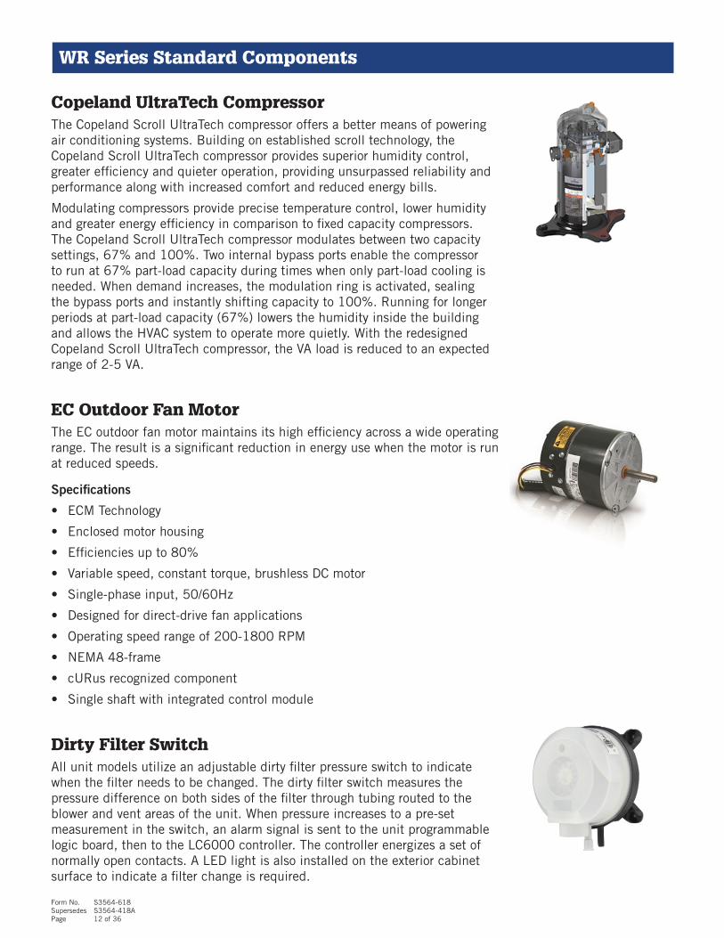
Large Display Service Tool Part #8301-053The large display service tool is used to communicate with the FUSION-TECTM unit logic board. Operation is identical to the TEC-EYETM, with a larger display and mechanical entry keys. By connecting directly to the logic board inside the unit control panel, it is possible to perform diagnostics on the unit, adjust certain settings and verify unit and economizer operation through a run test procedure.
Technical Specifications:
Storage Temperature: -4°F to 158°F (-20°C to 70°C)Operating Conditions: -4°F to 140°F (-20°C to 60°C)Display Type: FSTN graphicDisplay Backlighting: LEDGraphic Resolution: 132 x 64 pixelsSize of Display Area: 2.8'' x 1.4'' (72mm x 36mm)Connector: RJ12 (phone connector)Maximum Wire Length: 50m, 164 ft.Category of Resistance to Heat and Fire: Category D and BCategory of Immunity Against Voltage Surges: Category 2Index of Protection: IP65, UL Type 1
EEV Manual Adjustment Service Tool Part #2151-021The EEV manual adjustment tool allows for adjustment of the EEV (Electronic Expansion Valve) without the use of the unit logic board. The service technician can use this tool by removing the electronic head of the valve and attaching the adjustment tool. The tool houses magnets that interact with the valve to open or close the EEV for charging or evacuating the system without system power.
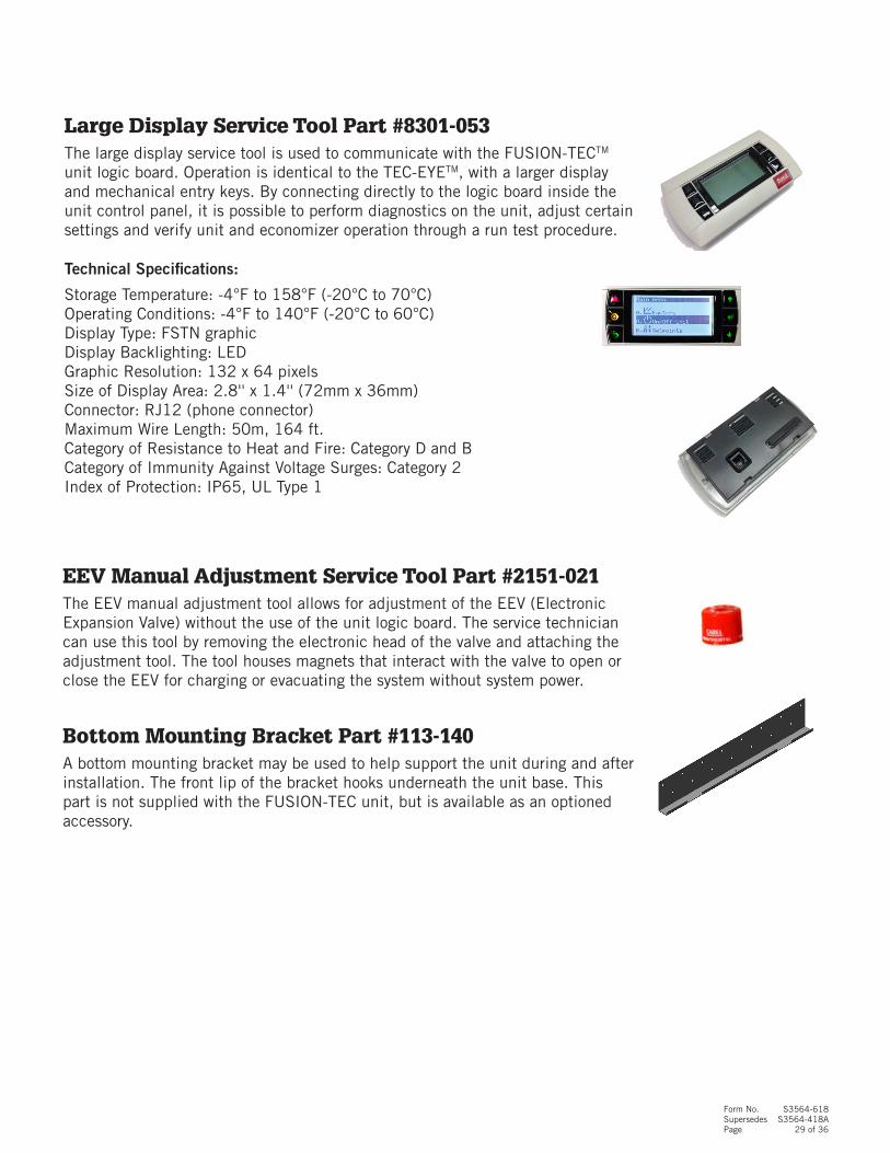
Bottom Mounting Bracket Part #113-140A bottom mounting bracket may be used to help support the unit during and after installation. The front lip of the bracket hooks underneath the unit base. This part is not supplied with the FUSION-TEC unit, but is available as an optioned accessory.

Form No. S3564-618Supersedes S3564-418APage 30 of 36
FUSION-TECTM Supply and Return Grilles (Sold Separately)
Part Number Description Shipping Weight Quantity Supplied
SGR-5W Supply Grille, 2" Wide Frame 6 pounds 1
RGR-5W Return Grille, 2" Wide Frame 12 pounds 1
16" x 30" Supply Grille, Wide Frame Part #SGR-5WThe FUSION-TEC™ unit requires a specially designed supply grille that allows for high velocity airflow through the unit supply opening. The grille finish is powder coated white. Wide frame grilles are used where wall hole sizes require a 2" wide grille flange to cover the wall opening. Used with WR36 and WR58 models.
10" x 30" Return Grille, Wide Frame Part #RGR-5WThe FUSION-TEC™ unit requires a specially designed return grille that allows for high velocity airflow through the unit return opening. Deflectors allow for air distribution at floor level, and are adjustable. The grille finish is powder coated white. Wide frame grilles are used where wall hole sizes require a 2" wide grille flange to cover the wall opening. Used with WR36 and WR58 models.

Form No. S3564-618Supersedes S3564-418APage 31 of 36
FUSION-TECTM Wall Curbs (Sold Separately)
Curb Model Description Shipping Weight
REWC5-*Wall curb that moves the unit away from the wall for unit replacement where the older unit supply is very close to roof line that extends away from the building.
57 pounds
REWC53-*
Wall curb that moves the unit away from the wall for unit replacement where the older unit supply is very close to roof line that extends away from the building. The REWC53 also allows for the WR36 or WR58 to replace an existing 3 on wall mount unit.
57 pounds
CAULK
CAULK
MIS-3910
CAULK
21 4 "
514"
* = x- Beige, 1- White, 4- Buckeye Gray, 5- Desert Brown, 8- Dark Bronze

Form No. S3564-618Supersedes S3564-418APage 32 of 36
WR Series Field-Supplied Istallation Items, Wiring
Component Reason for Use
Wiring – All Units
18 Gauge 2 Wire Shielded Cable with drain
This is required to communicate between each FUSION-TECTM unit and the LC6000 controller. When calculating wire length that is needed, be sure to include routing distance to each unit, conduit requirements and a loop for an EMI ferrite filter inside each unit control panel.
18 Gauge 5 Wire Shielded Cable with drain
This is required to communicate between the indoor remote temperature and humidity sensor and the LC6000 controller. When calculating wire length that is needed, be sure to include routing distance between the sensor location and controller, conduit requirements and routing inside the LC6000 panel to the terminal block. 18 gauge 6 wire shielded cable may be used if an extra conductor (wire) is desired.
Main Unit Power Wiring, 230VAC
This is required to supply power to the unit for compressor, ventilation and electric heat operation. When calculating wire length that is needed, be sure to include routing distance between the power source and the VAC circuit breaker inside the unit, and the conduit requirements. Be sure to follow all wire sizing and routing requirements supplied in this document and the installation manual.
LC6000 Controller Power Wiring,
This is required to supply power to the LC6000 controller. When calculating wire length that is needed, be sure to include routing distance between the power source and the VAC connection point inside the LC6000 controller, and the conduit requirements. Be sure to follow all wire sizing and routing requirements supplied in the LC6000 specification sheet and the LC6000 installation manual.
18 Gauge 2 Wire Shielded Cable
This is optional to communicate between an additional indoor temperature sensor and the LC6000 controller. When calculating wire length that is needed, be sure to include routing distance between the sensor location and controller, conduit requirements and routing inside the LC6000 panel to the terminal block.
Field-Supplied Installation Items, Bard GuardTM
Component Reason for Use
Wiring – All Units
18 Gauge 4 Wire Cable
This is required to communicate between FUSION-TECTM unit 1, unit 2 and the BG1000 security interface. When calculating wire length that is needed, be sure to include routing distance to each unit and conduit requirements. 18 gauge 6 wire cable may be used if extra conductors are desired.
18 Gauge 2 Wire Cable
This is required to communicate between FUSION-TECTM unit 3, unit 4 and the BG1000 security interface. When calculating wire length that is needed, be sure to include routing distance to each unit and conduit requirements. It is also required to communicate between the BG1000, the LC6000 and the 66 block NOC connection.
16 Guage LC Controller Power Wiring, -48VDC
This is required to supply power to the BG1000 security interface. When calculating wire length that is needed, be sure to include routing distance between the power source and the VAC connection point inside the BG1000, and the conduit requirements. Be sure to follow all wire sizing and routing requirements supplied in the BG1000 specification sheet and the installation manual.

Form No. S3564-618Supersedes S3564-418APage 33 of 36
18 Gauge 2 Wire Shielded Cable with DrainWhere specified, this wire is 18/2 18 Gauge Copper Conductor Stranded Shielded and a PVC jacket. Red and black are the preferred wire colors.
18 Gauge 5 Wire Shielded Cable with DrainWhere specified, this wire is 18/5 18 Gauge Copper Conductor Stranded Shielded and a PVC jacket. 18/6 (6 wire) may be used in place of 18/5 (5 wire) if an extra conductor is desired.
WR Series Field-Supplied Installation Items, Unit
Component Reason for Use
Unit Installation
Wall Fasteners for Unit
Ten (10) cement fasteners, wall lag bolts or other fasteners are required to mount the FUSION-TECTM product to the wall structure. Ø.375 holes are provided in the wall mounting flange on each side of the FUSION-TECTM unit. Fasteners must be field specified based on the wall structure.
Wall Fasteners for Rain FlashingSeven (7) cement or wood screws are required to mount the FUSION-TECTM rain flashing to the wall structure. Ø.250 holes are provided in the top of the rain flashing. Fasteners must be field specified based on the wall structure.
Exterior Silicone CaulkThis is required to form a watertight seal between the FUSION-TECTM unit and the wall. Choose an outdoor rated premium silicone caulk and follow all installation instructions provided with the FUSION-TECTM unit.
230VAC Main Unit Power ConduitThis is required to supply power to the unit for compressor, ventilation and electric heat operation. Hole plugs are provided on each side of the unit for 230V main power.
Communication Wire ConduitThis is required to supply communication to the unit logic control board. One hole plug is provided on each side of the unit for the communication wire.

Form No. S3564-618Supersedes S3564-418APage 34 of 36
Bard GuardTM Security SystemThe Bard GuardTM Security System is comprised of the following parts:
• Sensors and a speaker mounted in each unit. This is ordered by specifying the factory installed “S” control option as the last digit in the unit model nomenclature.
• The BG1000 Security Interface may be used for 1 to 4 units. This is sold separately and is installed inside the structure. Wires connect the BG1000 to the LC6000 series controller.
• A heavy duty hinged security frame that attaches to the unit. The security frame has four (4) locking nuts that require a special key to remove. The frame secures the front panels while allowing service access by removing the four (4) locking nuts and swinging the frame out of the way on four (4) provided hinges. This is ordered by specifying the factory installed “S” control option as the last digit in the unit model nomenclature.
WR Series Units with Bard GuardTM Security System
Bard GuardTM Electrical Diagram
LC6000
66 Block
Unit 1
-48VDCPower Power to BG1000
2 Wire
for Alarm
4 Wire for Alarm and Speaker Unit 1
2 Wire for Alarm Unit 3
2 Wire for Alarm Unit 4
Unit 2 Unit 3 Unit 4
BG1000Security Interface
Unit 1Speaker
UsedUnit 2
Speaker UsedUnit 3
Speaker Not Used
Unit 4Speaker Not Used
4 Wire for Alarm and Speaker Unit 2
2 Wire for Alarm

Form No. S3564-618Supersedes S3564-418APage 35 of 36
Bard GuardTM Security FrameThe Bard GuardTM Security frame provides a way to lock the front doors, unit top and condenser coil to deter theft of internal unit components. The frame is comprised of heavy duty steel angle iron and uses a hidden hinged system to allow easy access for servicing the unit. Four (4) locking nuts are provided to captivate the frame. A key is shipped with each unit to remove the locking nuts and provide access to internal components.
Bard GuardTM Unit "S" Controls OptionThe Bard Guard “S” Controls option is used to order the FUSION-TECTM unit with all required tamper resistant door switches and the internal 80db audio warning speaker. A loss of refrigerant pressure also sends an alarm signal. All components are pre-wired from the factory, and a simple four (4) wire connection is used to connect the FUSION-TECTM unit security options to the BG1000 Security Interface. Up to four (4) units can be used with a single BG1000 by running two (2) wires to each additional unit. Power is supplied by the BG1000 to operate up to two (2) unit audio warning speakers. The audio warning is given in both English and Spanish.
Bard GuardTM BG1000 Security Interface (Sold Separately)
The Bard Guard security interface mounts to the wall inside the structure. -48VDC power is used to operate the security system. Two (2) indicator lights are provided to display “Armed” or “Disarmed”. When armed, the system will apply power for up to 30 minutes to the unit speakers when unit system pressure is lost in any unit, or a door switch has been activated. An alarm signal will also be sent to the LC6000 controller. When disarmed, the system will remain inactive for up to 4 hours (user adjustable).
WR Series Units with Bard GuardTM Security System
WR Series w/ Bard GuardTM
BG1000 Audio Warning Device
BG1000 Bard GuardTM Interface

Bard Manufacturing Company, Inc. Bryan, Ohio 43506 www.bardhvac.com
Due to our continuous product improvement policy,all specifications subject to change without notice.
Before purchasing this appliance, read important energy cost and efficiency information available from your retailer.
Form No. S3564
June 2018
Supersedes: 418A
The following parts are unique to this product design and may not be found locally. Therefore, it is recommended that they be considered as "spares" for any mission critical installation so they would be immediately available should service ever be required. Refer to complete parts lists for more detail.
WR36 and WR58 FUSION-TECTM Inventory Starter Kit
Part # Description Notes
1 2151-021 EEV Adjustment ToolNeeded if EEV is to be opened while charging refrigerant with the unit power OFF.
2 3000-1578 0-10 VDC Adapter PlugSpecial plug for the control signal to the indoor blower motor.
3 400-0408 Fan Mount Assembly New for the WR series
4 S5151-060 Condenser Fan Blade Used in today's W**AA/W**LA
5 5651-244 EEV New for the WR36
6 5651-245 EEV New for the WR58
7 8201-130 Relay Used in today's W**AA/W**LA
8 8301-057 Filter Switch Used in today's W**AA/W**LA
9 8301-066 Discharge Air Sensor Used in today's D**A2/D**L2
10 8301-067 OAT & H Sensor Used in today's D**A2/D**L2
11 8301-068*** Micro PC3 Board New for the WR series
12 8301-073 Dust Sensor New for the WR series
13 8401-038 Compressor/Heater Contactor Used in today's "WR*V" Series
14 8406-142 High Pressure Cutout Used in today's W**AA/W**LA
15 8406-153 Low Pressure Transducer New for the WR series
16 8406-154 High Pressure Transducer New for the WR series
17 8407-065 Transformer New for the WR series
18 8408-044 10 K-Ohm Sensor Used in today's "W**HA" Series
19 8408-053 Freeze Stat New for the WR series
20 8552-096 40 mfd/440VAC Capacitor Used in today's I**AD Series
21 8602-067 Actuator Motor 0-10V Used in today's "W**AA" Series
22 8611-199 Pilot Light New for WR series
23 8612-061 Dust Sensor Board New for the WR series
24 S5154-002-0146 Blower Motor/Wheel New for the WR36
25 S5154-007-0142 Blower Motor/Wheel New for the WR58
26 S8105-070-0145 Condenser Fan Motor New for the WR36
27 S8106-061-0132 Condenser Fan Motor New for the WR58
28 S8201-164 CCM Used in today's W**AA/W**LA
29 2151-022 Tri-Groove Socket Key Required for Bard Guard Access
Page 36 of 36