frazer lake sockeye salmon fish pass and smolt … lake sockeye salmon fish pass and smolt...
TRANSCRIPT
Frazer Lake Sockeye Salmon Fish Pass and Smolt Monitoring Project Operational Plan, 2013
by
Steven Thomsen
April 2013
Alaska Department of Fish and Game Divisions of Sport Fish and Commercial Fisheries
Symbols and Abbreviations The following symbols and abbreviations, and others approved for the Système International d'Unités (SI), are used without definition in the following reports by the Divisions of Sport Fish and of Commercial Fisheries: Fishery Manuscripts, Fishery Data Series Reports, Fishery Management Reports, and Special Publications. All others, including deviations from definitions listed below, are noted in the text at first mention, as well as in the titles or footnotes of tables, and in figure or figure captions. Weights and measures (metric) centimeter cm deciliter dL gram g hectare ha kilogram kg kilometer km liter L meter m milliliter mL millimeter mm Weights and measures (English) cubic feet per second ft3/s foot ft gallon gal inch in mile mi nautical mile nmi ounce oz pound lb quart qt yard yd Time and temperature day d degrees Celsius °C degrees Fahrenheit °F degrees kelvin K hour h minute min second s Physics and chemistry all atomic symbols alternating current AC ampere A calorie cal direct current DC hertz Hz horsepower hp hydrogen ion activity pH (negative log of) parts per million ppm parts per thousand ppt, ‰ volts V watts W
General Alaska Administrative Code AAC all commonly accepted abbreviations e.g., Mr., Mrs.,
AM, PM, etc. all commonly accepted professional titles e.g., Dr., Ph.D., R.N., etc. at @ compass directions:
east E north N south S west W
copyright corporate suffixes:
Company Co. Corporation Corp. Incorporated Inc. Limited Ltd.
District of Columbia D.C. et alii (and others) et al. et cetera (and so forth) etc. exempli gratia (for example) e.g. Federal Information Code FIC id est (that is) i.e. latitude or longitude lat. or long. monetary symbols (U.S.) $, ¢ months (tables and figures): first three letters Jan,...,Dec registered trademark trademark United States (adjective) U.S. United States of America (noun) USA U.S.C. United States
Code U.S. state use two-letter
abbreviations (e.g., AK, WA)
Mathematics, statistics all standard mathematical signs, symbols and abbreviations alternate hypothesis HA base of natural logarithm e catch per unit effort CPUE coefficient of variation CV common test statistics (F, t, χ2, etc.) confidence interval CI correlation coefficient (multiple) R correlation coefficient (simple) r covariance cov degree (angular ) ° degrees of freedom df expected value E greater than > greater than or equal to ≥ harvest per unit effort HPUE less than < less than or equal to ≤ logarithm (natural) ln logarithm (base 10) log logarithm (specify base) log2, etc. minute (angular) ' not significant NS null hypothesis HO percent % probability P probability of a type I error (rejection of the null hypothesis when true) α probability of a type II error (acceptance of the null hypothesis when false) β second (angular) " standard deviation SD standard error SE variance population Var sample var

FRAZER LAKE SOCKEYE SALMON FISH PASS AND SMOLT MONITORING OPERATIONAL PLAN, 2013
by Steven Thomsen
Alaska Department of Fish and Game, Division of Commercial Fisheries, Kodiak
Alaska Department of Fish and Game Division of Sport Fish, Research and Technical Services 333 Raspberry Road, Anchorage, Alaska, 99518-1565
April 2013

The Regional Information Report Series was established in 1987 and was redefined in 2006 to meet the Division of Commercial Fisheries regional need for publishing and archiving information such as project operational plans, area management plans, budgetary information, staff comments and opinions to Board of Fisheries proposals, interim or preliminary data and grant agency reports, special meeting or minor workshop results and other regional information not generally reported elsewhere. Reports in this series may contain raw data and preliminary results. Reports in this series receive varying degrees of regional, biometric, and editorial review; information in this series may be subsequently finalized and published in a different department reporting series or in the formal literature. Please contact the author or the Division of Commercial Fisheries if in doubt of the level of review or preliminary nature of the data reported. Regional Information Reports are available through the Alaska State Library and on the Internet at: http://www.adfg.alaska.gov/sf/publications/.
Steven Thomsen Alaska Department of Fish and Game, Division of Commercial Fisheries
351 Research Court, Kodiak, AK 99615, USA
This document should be cited as: Thomsen, S. 2013. Frazer Lake Sockeye Salmon Fish Pass and Smolt Monitoring Operational Plan, 2013. [In]
Salmon and herring research operational plans for the Kodiak Area, 2013. Alaska Department of Fish and Game, Regional Information Report 4K13-04, Kodiak.
The Alaska Department of Fish and Game (ADF&G) administers all programs and activities free from discrimination based on race, color, national origin, age, sex, religion, marital status, pregnancy, parenthood, or disability. The department administers all programs and activities in compliance with Title VI of the Civil Rights Act of 1964, Section 504 of the Rehabilitation Act of 1973, Title II of the Americans with Disabilities Act (ADA) of 1990, the Age Discrimination Act of 1975, and Title IX of the Education Amendments of 1972.
If you believe you have been discriminated against in any program, activity, or facility please write: ADF&G ADA Coordinator, P.O. Box 115526, Juneau, AK 99811-5526
U.S. Fish and Wildlife Service, 4401 N. Fairfax Drive, MS 2042, Arlington, VA 22203 Office of Equal Opportunity, U.S. Department of the Interior, 1849 C Street NW MS 5230, Washington DC 20240
The department’s ADA Coordinator can be reached via phone at the following numbers: (VOICE) 907-465-6077, (Statewide Telecommunication Device for the Deaf) 1-800-478-3648, (Juneau TDD) 907-
465-3646, or (FAX) 907-465-6078 For information on alternative formats and questions on this publication, please contact:
ADF&G Division of Sport Fish, Research and Technical Services, 333 Raspberry Road, Anchorage AK 99518 (907) 267-2375.

TABLE OF CONTENTS Page
LIST OF FIGURES ....................................................................................................................................................... ii
LIST OF APPENDICES ............................................................................................................................................... ii
ABSTRACT .................................................................................................................................................................. 1
INTRODUCTION ......................................................................................................................................................... 1
Goal ............................................................................................................................................................................... 2 Objectives ...................................................................................................................................................................... 2 Tasks .............................................................................................................................................................................. 2 General .......................................................................................................................................................................... 2 Smolt Monitoring .......................................................................................................................................................... 2 Adult Monitoring ........................................................................................................................................................... 3 Supervision and Training ............................................................................................................................................... 3 PROCEDURES ............................................................................................................................................................. 3
Smolt Trap Installation .................................................................................................................................................. 3 Smolt Bypass System (Feasibility) Installation ............................................................................................................. 4 Smolt Trap Monitoring and Maintenance ...................................................................................................................... 5 Trapping Considerations:............................................................................................................................................... 5 FISH PASS OPERATION AND ADULT SAMPLING ............................................................................................. 10 OTHER REQUIREMENTS ........................................................................................................................................ 11
REFERENCES CITED ............................................................................................................................................... 14
FIGURES .................................................................................................................................................................... 15
APPENDIX A. SMOLT SAMPLING ......................................................................................................................... 25
APPENDIX B. FISH PASS MAINTENANCE AND OPERATION ......................................................................... 37 APPENDIX C. SATELLITE TELEPHONE AND DISPATCH INSTRUCTIONS ................................................... 41
APPENDIX D. WEEKLY REPORT EXAMPLE ....................................................................................................... 45
APPENDIX E. TOTAL (100%) CAPTURE FEASIBLIITY ...................................................................................... 47
i
LIST OF FIGURES Figure Page 1. Location of Frazer Lake on Kodiak Island, Dog Salmon Creek and the Barrier Falls. ................................. 16 2. Dog Salmon River trap placement. ............................................................................................................... 17 3. Smolt trap board walk. .................................................................................................................................. 18 4. Daily smolt mark-recapture catch reporting form. ........................................................................................ 19 5. Weekly smolt mark-recapture catch summary form. .................................................................................... 20 6. Smolt dye release form. ................................................................................................................................. 21 7. Weekly salmon escapement enumeration form. ............................................................................................ 22 8. Daily physical observation form. .................................................................................................................. 23
LIST OF APPENDICES Appendix Page A1. Statistical (sampling) weeks and associated calendar dates. ......................................................................... 26 A2. Procedure for sampling smolt age, length, and weight. ................................................................................. 27 B1. Fish pass maintenance and operation. ........................................................................................................... 38 C1. Satellite telephone and dispatch instructions. ................................................................................................ 42 D1. An example of a biweekly report. ................................................................................................................. 46 E1. Diversion weir installation. ........................................................................................................................... 48 E2. Timed counts instructions. ............................................................................................................................ 49 E3. Daily smolt 100% catch reporting form. ....................................................................................................... 50 E4. Smolt 100% catch reporting summary form. ................................................................................................. 51 E5. Catch-Weight instructions. ............................................................................................................................ 52 E6. Catch-Weight Worksheet. ............................................................................................................................. 53
ii

ABSTRACT Frazer Lake, within the Kodiak Management Area, was originally devoid of anadromous fish species due to a 10-meter barrier waterfall. From 1951 to 1971, sockeye salmon Oncorhynchus nerka were introduced to Frazer Lake. In 1962, a fish pass was constructed around the barrier fall to allow fish to migrate up into the lake system. Since construction of the fish pass, the Alaska Department of Fish and Game (ADF&G) has annually operated and maintained the fish pass structure to ensure sockeye salmon are able to access Frazer Lake. Additionally, ADF&G enumerates and collects biological data from sockeye salmon smolt and adults. This operational plan is intended to provide the field staff with a reference document for the daily operations of the Frazer Lake fish pass and smolt operations during the 2013 field season.
Key words: Frazer, Dog Salmon, Olga Bay, Sockeye Salmon, Oncorhynchus nerka, smolt, fish pass, bypass, fish ladder, weir.
INTRODUCTION Frazer Lake is located on the southern end of Kodiak Island and is the second largest lake within the Kodiak Archipelago (Figure 1). Frazer Lake is 14.2 km long, and 1.6 km wide, with a surface area of 16.1 km2. Dog Salmon Creek is the outlet of Frazer Lake and drains into Olga Bay. Prior to 1951, Frazer Lake was void of sockeye salmon Oncorhynchus nerka because of a 10-meter barrier waterfall, which prohibited anadromous fish from entering the lake (Russell 1972). Egg, fry, and adult transplants (1951–1971) from sockeye salmon systems on Kodiak Island (Karluk and Red lakes) and the Alaska Peninsula (Becharof Lake) were used to establish a sockeye salmon run to the Frazer system with adults returning for the first time in 1956 (Russell 1972). From 1956 to 1961, returning adults were backpacked around the falls and, in 1962, a fish pass was constructed to allow returning salmon to access the lake environment. A second fish pass was installed in 1979, with the intention of increasing fish passage during peak migration periods.
Conservative fishery management practices built the Frazer Lake run from 25,000 sockeye salmon in 1971 to 645,739 fish in 1985. Blackett (1979) estimated a spawning capacity of 365,000 adults based upon limnological and spawning habitat information. Declines in smolt condition and shifts in zooplankton size and community composition prompted lowering the escapement goal range to 200,000–275,000 adults in 1986 (Kyle et al. 1988). The goal was lowered again to 140,000–200,000 in 1988 (Nelson and Lloyd 2001). The current biological escapement goal of 75,000–170,000 fish is based on stock-recruit analysis, and has been in place since 2008 (Nemeth et al. 2010). A fertilization program was instituted from 1988 to 1992 in response to the declines in smolt size that resulted from the large escapements into the lake from 1980 through 1982 and in 1985.
Sockeye salmon adult enumeration and age, sex, and length (ASL) sampling have been conducted annually at the Frazer Lake since 1956. Since 1985, smolt age, weight, and length (AWL) data and zooplankton density and community composition have been measured annually. Smolt emigration estimates and timing have been obtained inconsistently since 1985.
In 1983, a weir was installed on Dog Salmon Creek, located 0.7 km upstream from lower Olga Bay. The purpose for the Dog Salmon weir was to obtain chum O. keta, and pink salmon O. gorbuscha escapement counts and more timely sockeye salmon counts.
This document provides a description of the current research conducted at Frazer Lake and specific methods to use for data collection in 2013.
1
GOAL The project goal is to operate the fish pass to allow adult fish passage into Frazer Lake, while collecting important adult and juvenile data to help manage the Frazer Lake sockeye salmon stock.
OBJECTIVES To achieve the project goal, ADF&G research personnel will:
1. Estimate the sockeye salmon smolt outmigration from Frazer Lake, 2. Estimate average age, weight, length (AWL), and condition of sockeye salmon smolt
emigrants from Frazer Lake, 3. Evaluate water chemistry, nutrients, and zooplankton in Frazer Lake, 4. Enumerate adult salmon escapement through Frazer fish pass; providing unobstructed and
timely adult fish passage to Frazer Lake, 5. Estimate age, sex, and length (ASL) composition of adult sockeye salmon escapements into
Frazer Lake.
TASKS GENERAL 1. Set up camp. Target date: 1–5 May. 2. Collect physical data daily: air temperature, water temperature, water level, cloud coverage,
wind direction and velocity, and precipitation. 3. Collect water and zooplankton samples at stations 1 and 3 approximately every four weeks
from May to October at Frazer Lake (This will be conducted by Heather Finkle and Darin Ruhl as per the Lake Assessment operational plan; Ruhl 2013 and Thomsen 2008).
SMOLT MONITORING Mark-Recapture
4. Install and operate an inclined-plane trap to estimate the abundance of smolt using mark-recapture methods. Mark-recapture is necessary to estimate trap efficiency, which is used to estimate the total smolt emigration. This trap will be fished continuously to capture a target goal of 5–7% of the total sockeye salmon smolt emigrants. Adjustments to trap wing length will be necessary if the capture rate is outside of the goal.
5. Enumerate the daily smolt trap catch of all fish by species. 6. Capture 1,050 sockeye salmon smolt weekly to estimate trap efficiency. Of the 1,050
sockeye salmon smolt captured, mark 1,000 using Bismarck Brown Y (BBY) dye. Fifty unmarked smolt will be held to estimate holding mortality. One hundred of the marked (dyed) sockeye salmon smolt will be held to estimate delayed mortality.
7. Collect AWL data from 40 sockeye salmon smolt five days a week for a total of 200 sampled smolts per week throughout the outmigration. If a large outmigration occurs on a day without scheduled sampling, additional sampling may be required.
8. Estimate the daily emigration of sockeye salmon smolt using individual, catch-weight, and/or timed counts.
2
Smolt By-Pass Feasibility 9. Explore the feasibility of capturing 100% of the sockeye salmon smolt emigrants utilizing a
smolt trapping and pipeline system.
ADULT MONITORING 10. Install, operate, and maintain the “old” (near shore) fish pass continuously until a decision to
close the fish pass is made by the project biologist. Target dates: approximately 15 May–1 September.
11. Enumerate the daily adult salmon escapement by species, and record the number of net-marked and “jack” (400 mm or less) sockeye salmon escaping through the fish pass.
12. Collect representative scales (random; for age determination), length, and sex from a minimum of 80 adult sockeye salmon three times per week for a minimum total of 240 ASL sampled fish per statistical week escaping to Frazer Lake.
SUPERVISION AND TRAINING Project Biologist: Steven Thomsen – Project Biologist (Fishery Biologist II)
Field Staff: Theresa Woldstad – Crew leader (Fish and Wildlife Tech. III)
Tyler Block – Crew member (Fish and Wildlife Tech. II)
Vacant – Crew member (Kodiak Regional Aquaculture Association Employee)
The project biologist will oversee the project, provide logistical and technical assistance, and write final reports. The crew leader will implement ADF&G safety guidelines, schedule daily tasks, oversee daily operations, and make sure data are complete and accurate. The crew members will assist the crew leader in all assigned tasks and field operations.
All field personnel will receive onsite training detailing salmon sampling protocols, field operations, radio and satellite communications, bear awareness, proper use of firearms, boat handling and operation, fish pass and weir operations, smolt trap installation and use, and daily facility operations.
PROCEDURES A single-site mark-recapture method will be used to estimate the sockeye salmon smolt emigration from Frazer Lake. The single inclined-plane trap will be used to capture smolt for marking, estimate the mark-recapture rate, and estimate smolt abundance.
In addition, the feasibility of using a smolt bypass system to achieve a 100% capture of emigrating sockeye salmon smolt and replacing the mark-recapture method will be tested. The bypass system will divert smolt traveling downstream from the lake through a pipe, circumventing the falls.
SMOLT TRAP INSTALLATION The single inclined-plane trap will be located just upstream of the 10 m waterfall and just above the concrete water diversion system (Figures 2 and 3).
3
Installation of the Trap Place the trap where the water velocity is sufficient to force smolt into the catch box while ensuring that smolt are not injured (scale loss, pinned against the perforated sheeting, etc.).
1. Install the inclined-plane trap in Dog Salmon Creek just upstream of the 10 m waterfall and just above the concrete water diversion system.
2. Anchor the trap with cables and turnbuckles to positions on the stream bank.
3. Use 3.0 m (10’) sections of 5.1 cm (2”) diameter pipe joined by NU-RAIL fittings as a frame to secure and support the trap.
4. Use a come-a-long, secured to the overhead steel pipe cross member, to elevate the downstream end of the trap.
5. Install a catch box to the codend of the trap for smolt capture.
6. Install a board walk and work platform leading from the bank to the catch box. Build the board walk using rackmaster supports and 2x12 boards (Figure 3).
Installation of Trap Wings The instructions below describe methods to increase the capture of emigrating smolt. The length and extent of the wings will depend on the weekly mark-recapture rate and should be adjusted to target a 5% to 7% capture rate.
1. Construct wings upstream of the trap in a “V” configuration using a frame made from 1.6 m (5’) legs, and 2.8 m (8’) cross members, 5.1 cm (2”) diameter pipe and NU-RAIL fittings. Leg lengths may be altered to decrease the wing angle, increase flow speed and decrease the potential of pinning smolt.
2. Attach 1.3 by 2.5 m (4 x 8’) sheets of aluminum perforated plate to the frame starting at the trap and working upstream. The first sheet of perforated plate is secured to the side of the trap with screws where the plate and the side of the trap are joined. The trap and perforated plate should rest on the streambed; continue placing sheets of perforated plate on the frame with each upstream piece overlapping the previous downstream piece by approximately six inches and securing the plates together with bailing wire.
3. Place Lortex (black plastic screen) over the seams of the perforated plate and any other areas with protruding edges that may be hazardous to smolt.
4. Line the inside walls and bottom of the trap with a blue tarp and/or Lortex as needed to minimize smolt pinning against the perforated plate and increase water velocity.
SMOLT BYPASS SYSTEM (FEASIBILITY) INSTALLATION Sockeye salmon smolt will be piped from a Canadian fan trap into the smolt shack, and then the smolt will proceed through the fish pass and exit downstream of the falls. Place the Canadian fan trap 0.5 km upstream of the inclined-plane trap following the methods describe for the inclined-plane trap (Figure 2).
4

Installation of Pipe through Fish Pass Structure 1. Connect sections of 6” high-density polyethylene pipe inside the entire length of the new fish
pass (far bank). These sections will remain connected inside the fish pass over winter. For winterization drain water from the pipeline and cover ends.
2. A short section of flex pipe may be needed at the bottom of the fish pass to decrease the rate of flow and prevent smolt mortality. Remove this section for winter storage.
Connecting the Upper Pipe to the Trap 3. Connect a section of pipe with a camlock fitting on one end to the downstream end of the
Canadian fan trap.
4. Attach additional sections of pipe paralleling the adult holding tank. The last section of pipe must end with a cam lock fitting.
5. Attach a section of flex pipe with cam lock on one end and position so the open end rests on the lip of the counting tank. Secure pipe to prevent movement.
6. The water level in the counting tank is adjusted with a valve on the standpipe located on the downstream end of the tank. Adjust the volume of water flowing into the tank by raising or lowering the trap or adjusting lining on the trap and wings.
Connecting the Lower Pipe to the Trap 7. Attach a short section of flex pipe with cam lock on one end to the exit tank fitting and bolt
to the pipe in the fish pass.
SMOLT TRAP MONITORING AND MAINTENANCE The trapping system will be operated to maintain efficiency and minimize smolt mortality. This requires frequent monitoring and maintenance since significant mortality can occur in a short period of time. Some mortality may also occur due to high water pressure, which results in smolt being pinned on the perforated plate.
TRAPPING CONSIDERATIONS: • Keep the traps and wings free of debris to maintain consistent trap efficiency and
minimize smolt mortality.
• Monitor traps frequently. The traps should be checked every 3–4 hours during the day and every 1–2 hours at night when in use.
• The downstream trap (inclined-plane) will be fished continuously for the duration of the smolt emigration (~1 May until ~2 July) and attention to changes in migration patterns will be monitored and recorded (i.e., rain may trigger a large emigration).
• Modify or pull wings from the water to allow smolt to pass safely if unforeseen conditions occur and smolt trapping must temporarily cease. If possible, any modifications to the trapping system will be discussed with the project biologist before implementation. If immediate modifications are necessary to avoid major mortality or loss of equipment, the project biologist will be notified as soon as possible.
5
• Plastic sheeting may need to be added to the perforated plates to reduce pinning or increase flow into the trap.
• Smolt will be handled with care, as sockeye salmon smolt are very sensitive to any stress, and mortality can occur through the loss of just a few scales.
• Use a dip net to remove and release the fish as they are counted.
• A tally denominator will be used to enumerate the smolt to ensure an accurate count.
Smolt Trap Catch and Emigration Estimates Since smolt primarily migrate at night, a single trapping or sampling day will be the 24-hour period from noon of the first day to noon the following day and the date will correspond with the first day. Smolt needed for sampling will be held in a live-box until sampled.
Proper identification of sockeye salmon smolt is crucial. A helpful source for juvenile salmonid identification is the ‘Field Identification of Coastal Salmonids’ by Pollard et al. (1997). It is the responsibility of the crew leader to ensure species are properly identified. If in doubt, freeze a sample for later verification or email a low resolution photograph to the Kodiak office.
All smolt entering the inclined-plane trap (lower) will be counted unless the crew is inundated, risking smolt mortality. If inundated with too many smolt refer to Appendices E2 through E6 for timed counts or catch-weight procedures. Please review the catch-weight equipment needs and process before needed. If conducting a mark-recapture test, all smolt must be visually inspected for marks (dye) and counted.
Smolt Enumeration Data Management All data will be entered on the appropriate form or log book and kept in a binder at camp. Digital records of these forms will be sent to the Kodiak office by email or on a memory stick bi-weekly or when re-supplied.
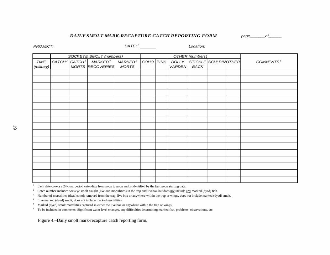
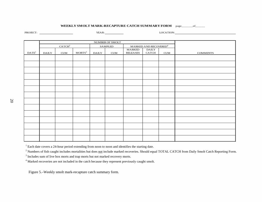
Record all smolt enumeration data, including smolt mortality, on the Daily Smolt Mark-Recapture Catch Reporting Form (Figure 4) and the Weekly Smolt Mark-Recapture Catch Summary Form (Figure 5). Additional forms and procedures will be needed if conducting timed counts (Appendices E2, E3, and E4) or catch-weight (Appendices E5 and E6) and for the feasibility testing.
Smolt Trap Efficiency and Mark-Recapture Trap efficiency estimates are necessary to estimate the total number of sockeye salmon smolt outmigrating from Frazer Lake. Mark-recapture trials will be conducted to determine the percentage of the outmigration the trap is catching. Delayed mortality and holding mortality tests will be conducted to adjust trap efficiency estimates.
Bismarck Brown Y (BBY) dye will be used to mark and identify the smolt used for the mark-recapture and delayed mortality trials. Trap efficiency estimates will be conducted weekly at the start of strata. The smolt season will be divided into nine strata: stratum 1 (1 May–7 May), stratum 2 (8 May–14 May), stratum 3 (15 May–21 May), stratum 4 (22 May–28 May), stratum 5 (29 May–4 June), stratum 6 (5 June–11 June), stratum 7 (12 June–18 June), stratum 8 (19 June–25 June), and stratum 9 (26 June–2 July; Appendix A3). Additional strata may be added to account for changes in estimation methods, insuring strata are independent.
6

The dyeing process can be very stressful to smolt, so every effort should be made to minimize and avoid unnecessary handling of the smolt during the process. Excessive handling (netting), increased water temperatures, transport, and exposure to the dye are the primary stresses. Individually, these can induce mortality. The following methods will be used for marking and releasing smolt:
• Once a week, 1,050 sockeye salmon smolt will be collected for marking or holding trials. If the emigrating run strength is not sufficient to capture 1,050 smolt in one night, smolt will be collected and held in a live-box for up to two days.
• Of the 1,050 sockeye salmon smolt collected, 1,000 sockeye salmon smolt will be marked and 50 will remain unmarked. Approximately, 900 dyed smolt will be released and 100 dyed smolt will be retained to monitor delayed mortality. In addition, the 50 unmarked smolt will be retained to monitor holding mortality. Non released smolt (100 marked and 50 unmarked) will be held and assessed separately under similar conditions. Smolt sampled for AWL will not be used in these tests.
• Dye marking with BBY will take place at the release site after transport. All data will be recorded on the Smolt Dye Release Form (Figure 6).
• For transport, nearly fill a 32-gallon garbage can with stream water with a bilge pump (water needs to be clean and cool, from a deep pool).
• If excessive mortality occurs (greater than 5%) institute the follow procedure for subsequent transport in the garbage can. Add sodium bicarbonate (baking soda) to obtain a 0.25% (1 g/gal or 264 mg/l) solution to maintain a stable blood pH. Add non-ionized salt to achieve a 0.75% solution (3 g/gal or 793 mg/l). This solution level approaches physiological levels and reduces metabolic stress and electrolyte depletion that can cause mortality.
• Place an oxygen hose with air stone in the garbage can and adjust to maintain 9 mg/l or 100% saturation throughout transport.
• Following transport, all smolt will be held in the garbage can for a minimum of 30 minutes to relax. Maintain oxygen saturation and keep the water temperature within 2°C of initial transport. Smolt displaying “abnormal” behavior will NOT be released as part of the test or retained for delayed mortality. A fish with “abnormal” behavior may be swimming on its side, upside down, puffing or flaring gills continuously. All dead and “abnormal” fish that are discovered at this stage of the dye test must be removed from this test population, returned to the river DOWNSTREAM of the smolt trap and recorded on the Smolt Dye Release Form as mortality in its perspective cell.
• After the 30 minute resting period, dissolve ~ 3 mg/l of BBY dye (4.0 g/30 gallons BBY premixed into a small amount of water) in the garbage can with the 1,000 smolt (make sure to remove the 50 non-dyed smolt before adding the dye) and monitor oxygen and temperature continuously. Water temperature and dissolved oxygen will be recorded in the mark-recapture log book throughout the process.
• For the marking process, all smolt will remain in the garbage can for a minimum of 60 minutes. To avoid diluting the dye, do not add any river water to adjust the temperature during the marking process.
7

• After the marking process, use the bilge pump to replace the dye with river water. Overflow holes in the garbage can allow excess water to be removed.
• Dyed smolt displaying “normal” behavior will be counted (up to 900) and released evenly across the creek with the use of water filled buckets. The process should be timed such that smolt will be released at approximately 2200 hours. The remaining 100 marked and 50 unmarked smolt will be held separately in a live box up to four days to determine smolt survival from the marking and holding tests (4 days unless excessive mortality occurs).
• Monitor the inclined-plane smolt trap for marked smolt daily from the day of the release and continue until the next dye test. The number of dyed smolt observed will be recorded on the Daily Smolt Mark-Recapture Catch Reporting Form (Figure 4) and the Weekly Smolt Mark-Recapture Summary Form (Figure 5). The daily smolt catch will not include recaptured marked smolt as they were already counted. The trap efficiency from each dye test will be identified as a percentage of the dyed fish recovered divided by the dyed smolt released (less holding mortality).
Delayed and Holding Mortality Experiments Dye tests are used to estimate the mortality of dyed smolt after they are. This experiment is comprised of two parts. The 100 marked smolt placed in the live box will be monitored daily for mortality over a four-day period. The 50 unmarked smolt placed separately in the live box will also be monitored daily for mortality over a four-day period. The mortality of both smolt groups will be entered separately to assess both holding and marking mortality. Additionally, check the marked smolt for mark visibility each day to insure mark retention.
Smolt used for the mortality experiment will be handled the same way as the smolt being released, except they will not be released.
Population Abundance Estimates of population abundance will be calculated using a modification of the stratified Peterson estimator (Carlson et al. 1998). Trap efficiency Eh for stratum h was calculated as
11++
=h
hh M
mE , (1)
where
Mh = number of marked smolt released in stratum h
mh = number of marked smolt recaptured in stratum h
A modification of the stratified Petersen estimator (Carlson et al. 1998) was used to estimate the number of unmarked smolt Uh emigrating within each stratum h as
1
) 1 ( ˆ + + =
h h h
h m M u U
, (2)
where
uh = number of unmarked smolt recaptured in stratum h.
8

Variance of the smolt abundance estimate was estimated as
( ) ( )( )( )( ) ( )21
11ˆrav 2 ++−+++
=hh
hhhhhhh mm
umMmuMU . (3)
Total abundance of U of unmarked smolt over all strata was estimated by
∑=
=L
hhUU
1
ˆˆ , (4)
where L is the number of strata. Variance for U was estimated by
( ) ( )∑=
=L
hhUvU
1
ˆˆrav , (5)
and 95% confidence intervals were estimated using
( )UU ˆ96.1ˆ ν± , (6)
which assumes that U is approximately normally distributed.
Within each stratum h, the total population size by age class j was estimated as,
jhhjh UU θˆˆ = , (7)
where jhθ is the observed proportion of age class j in stratum h. Variance of jhθ was estimated using the standard variance estimate of a population proportion (Thompson 1987). The variance of jhU was then estimated by
( ) ( ) ( )22 ˆˆˆˆˆrav jhhjhhjh vUvUU θθ += . (8)
The total number of emigrating smolt within each age class was estimated by summing the individual strata estimates, and its variance was likewise estimated by summation over the individual strata estimates.
Assumptions for the mark-recapture experiment are described in Carlson et al. (1998).
Age, Weight, and Length Sampling The random collection of AWL data from 40 sockeye salmon smolt will occur five days a week for a total of 200 smolt sampled per week. If a large outmigration occurs on a day without scheduled sampling, additional sampling may be required. Report the number of AWL samples and on the Weekly Smolt Mark-Recapture Summary Form (Figure 5). AWL data will be kept in a log and entered into a Rugged Digital Assistant (RDA). Specific procedures for sampling and recording smolt AWL data are in Appendix A. Each sample should be taken from a single day’s catch. Do not mix samples between days. If less than 40 fish are caught in a day, the sample size for that day will be the number of fish caught on that day. Marked smolt will not be included with random AWL sampling.
9
Bypass System Feasibility The feasibility of capturing 100% of the smolt to estimate total outmigration will be conducted. Fully utilizing this method requires estimating the daily emigration of sockeye salmon smolt using individual timed counts, and possibly catch-weights. The feasibility of capturing 100% of the smolt will be conducted during periods of slow smolt emigration (i.e. during the beginning and end of the outmigration) and will only be conducted at the end of a stratum to prevent the possibility of missing marked smolt and biasing mark-recapture testing. The project biologist will inform the crew when to conduct the feasibility testing. Additional methods and forms are provided in Appendix E for use when testing the 100% capture feasibility.
Termination of Smolt Monitoring The smolt trap and diversionary system will be removed at the end of the smolt emigration, which is expected to be approximately 1 July. The exact date will be determined by the project biologist based on trap catch performance.
FISH PASS OPERATION AND ADULT SAMPLING Fish Pass Procedures The shoreward (“old”) fish pass will be operated from approximately 15 May through 1 September. Operation will begin a minimum of two days after sockeye salmon are first counted through Dog Salmon weir. The far “new fish pass” will be used only for smolt outmigration. Diversion weirs above and below the Frazer falls should be inspected daily for holes and cleaned when required. Specific instructions for fish pass maintenance and operations are provided in Appendix B. These steps prevent fish from escaping through the lower diversion weir, which has been a major problem in the past. All weir panels on the lower diversion weir should be tightly connected at the base. Panels fit in a channel formed by two pieces of angle iron. This “groove” needs to be cleaned out prior to installing the lower weir. Underwater “Aqua scopes” are used to check the alignment of panels in the groove. Special attention should be paid to the alignment of the weir panels underwater because fish which escape through the lower diversion weir become trapped at the base of the falls.
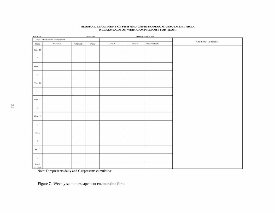
Salmon escapements through the fish pass will be counted and reported on a daily basis. Counting frequency will have to be increased during the peak of the escapement to minimize migration delays. Individual counting events will be tallied by species using hand-held tally denominators and summed at the end of the day. All jack sockeye salmon (≤ 400mm) and net marked sockeye salmon will be included in the total sockeye salmon escapement and will be individually enumerated and recorded on daily basis to assess the escapement quality. All escapement data will be recorded on the Weekly Salmon Escapement Enumeration Form (Figure 7).
Escapement Sampling Adult sockeye salmon will be captured and sampled at the top of the fish pass throughout the summer escapement season. Details and procedures for adult sampling are outlined in the Kodiak Management Area sockeye salmon catch and escapement sampling operational plan, 2013 (Moore 2013).
10
OTHER REQUIREMENTS Safety In the event of a life-or-limb emergency, contact should be made directly to USCG emergency rescue at 1-800-478-5555 or VHF Channel 16 and then to the project biologist.
The Frazer Cabin is located at 57°12.1’ N lat and 154°3. State of Alaska safety regulations and Standard Operating Procedures (SOPs) must be followed at all times. On-site personnel will exercise extreme caution when considering safety issues. Employees not following state safety regulations may be subject to disciplinary action, including termination. Employees are expected to review, understand and sign the following SOPs before field deployment. Sections of the SOP that are required reading for field personnel include 111-700 Safety Policies and Standards 111-740 Boating Safety
111-710 Office/Warehouse Safety 111-750 Vehicle Safety
111-720 Field Camp Safety 111-760 Laboratory Safety
111-730 Aircraft Safety for Passengers 111-780 Firearm/Bear Safety
In addition, all employees are required to hold a current American Red Cross First Aid/CPR certification. First Aid/CPR classes will be held in Kodiak prior to the field deployment. An approved personal flotation device will be worn at all times while boating. A survival kit including matches, VHF radio, flare gun, EPIRB, spare motor parts, and a first aid kit will also be in the boat at all times.
Climate Data Collect climate data at noon each day. Record the information on the Daily Physical Observation Form (Figure 8). These data will include water and air temperatures (οC), stream height (cm), estimated percent cloud cover, and wind direction and velocity (km/hr). Measure stream height from a stream gauge in a location that is not directly affected by the trap, or the fish pass water diversion system.
Radio Schedule During the smolt season (May–June), Kodiak Research office personnel will contact field camps by satellite phone on the dispatch service every day of the week between 1300 and 1315 (1:00–1:15 PM) hours. After the smolt trap is removed and smolt operations are over, the daily communication schedule will change; consisting of daily radio communication with Kodiak Management staff every morning between 0810–0830 (8:10–8:30 AM) and daily communication with Kodiak Research office personnel every morning between 0845–0900 (8:45–9:00 AM) via Single Side Band (SSB) radio on frequency 3.230 kHz. Instructions on the operation and transmission of the satellite phone are provided in Appendix C. The emergency Coast Guard frequency for the SSB is 4.125 kHz. The morning radio communication is an important tool which provides local air charter pilots with the current weather conditions and provides the most recent escapement data to fishery
11

managers who utilize this information to make daily management decisions. The Commercial Fishery Management Section also maintains an afternoon radio schedule for their management weirs at 1630 hr (4:30 PM) which is an optional radio communication. If contact to the Kodiak office is necessary at other times, information can be transmitted via the satellite telephone, with the satellite dispatch service, with the SSB radio, or by email. Reporting
The field crew will be responsible for compiling biological data, photo documentation, drafting bi-weekly reports, writing an end of season summary report, providing daily radio reports and maintaining a camp journal. Hard copies of data forms and the camp journal will be completed on a daily basis. “Rite in the rain" logbooks will be used for ASL and AWL sampling. After completing a sampling event and upon returning to the cabin the data will be transferred to the corresponding data forms and entered into the RDA. On a daily basis the current weather conditions, escapement numbers, and smolt trap catches will be reported to the Kodiak office via satellite phone or SSB radio. In addition a brief report of project activities will be sent to town every two weeks, by email or via resupply/mail plane. A sample of the activity report is located in Appendix D. In preparation for the resupply flights, the activity report and the adult and juvenile scale samples will be properly packaged and clearly labeled with ADF&G Attn: Steven Thomsen 486-1872. MAKE SURE TO CHECK NUMBERS BEFORE PASSING THEM ON TO TOWN.
Resupply Resupply items (e.g., groceries, fuel, mail, etc.) will be sent via chartered float plane on a bi-weekly basis. All air charter flights will be set up through the Kodiak office staff. Appropriate information in regard to fight logistics and times will be relayed via the daily radio communications. Small lists can be relayed over the Single Side Band radio or satellite phone; however, these lists should be limited to just a few items. Blank grocery lists will be available in the field so the crew can place orders 2 weeks in advance for preparation of the next supply flight. It should also be remembered that the grocery budget allocates $25/day/person and this allocation will not be exceeded. If it becomes apparent the grocery budget is being surpassed the project leader will notify staff so appropriate reductions can be made. When planning for the resupply flights it is import to prepare back haul items and maximize the use of the chartered aircraft. Items to send back to town include empty fuel containers, non-burnable trash, biological data, and reports. When back hauling items it is important to notify office personnel of the expected items. During the bear viewing season some items may be sent as freight with air charter services visiting Frazer.
Visitors / Public Interaction • Many people visit Frazer Lake participating in activities ranging from day-use fishing
and bear viewing to extended use through the Refuge cabins or campers. Most of these visitors come by the cabin site because the falls attract bears and provide excellent bear viewing opportunities. Visitors are also interested in seeing the fish exiting the fish pass. Due to this frequent contact, the camp must be kept clean and presentable. The field staff will act in a professional and courteous manner that is helpful to visitors. Visitors must also be informed of boundaries, limitations, and hazards. Be helpful, but remember the primary role of ADF&G staff is to run the smolt and adult sockeye salmon research project. USFWS will have personnel available to interact with the public during the peak bear viewing season to limit interruptions to ADF&G staff.
12

• If possible, the crew should try to perform routine maintenance on the weir before 9 AM and after 5 PM to limit bear viewing disturbances. When work that may cause bear viewing disturbance is necessary, inform bear viewers of your intentions before proceeding with work. Also try to limit hazing of bears when bear viewers are present but do not sacrifice camp operations or staff safety.
• Crew will not allow film crews into compound area or interviews with staff if not pre-authorized.
Camp Inventory and Closure The Frazer Lake project equipment will be inventoried prior to camp closure. A list of the equipment needed for the next field season should also be provided. The project biologist will provide directions for properly securing the cabin and out buildings prior to the field crew leaving the camp site.
13
REFERENCES CITED Blackett, R. F. 1979. Establishment of sockeye (Oncorhynchus nerka) and chinook (O. tshawytscha) salmon runs
at Frazer Lake, Kodiak Island, Alaska. Journal of Fisheries Research Board of Canada 36:1265-1277.
Carlson, R. S., L. G. Coggins Jr, and C. O. Swanton. 1998. A simplified stratified design for mark-recapture estimation of salmon smolt abundance. Alaska Fishery Research Bulletin. 5(2) 88-102.
Honnold, S. G., M. J. Witteveen, M. B. Foster, I. Vining, and J. J. Hasbrouck. 2007. Review of escapement goals for salmon stocks in the Kodiak Management Area, Alaska. Alaska Department of Fish and Game, Fishery Manuscript No. 07-10, Anchorage.
Kyle, G. B., J. P. Koenings, and B.M. Barrett. 1988. Density-dependent, trophic level responses to an introduced run of sockeye salmon (Oncorhynchus nerka) at Frazer Lake, Kodiak Island, Alaska. Canadian Journal of Fisheries and Aquatic Sciences 45:856-867.
Nelson, P. A., and D. S. Lloyd. 2001. Escapement goals for Pacific salmon in the Kodiak, Chignik, and Alaska Peninsula/Aleutian Islands Areas of Alaska. Alaska Department of Fish and Game, Division of Commercial Fisheries, Regional Information Report 4K01-66, Kodiak.
Moore, M. 2013. Kodiak Management Area sockeye catch and escapement sampling operational plan, 2013. [In] Salmon and herring research operational plans for the Kodiak area 2013. Alaska Department of Fish and Game, Regional Information Report 4K13-04, Kodiak.
Nemeth, M. J., M. J. Witteveen, M. B. Foster, H. Finkle, J. W. Ericson, J. S. Schmidt, S. J. Fleischman, and D. Tracy. 2010. Review of escapement goals in 2010 for salmon stocks in the Kodiak Management Area, Alaska. Alaska Department of Fish and Game, Fishery Manuscript Series No. 10-09, Anchorage.
Pollard, W. R., G. F. Hartman, C. Groot, and P. Edgell. 1997. Field Identification of Coastal Juvenile Salmonids. Harbour Publishing. Madeira Park, BC Canada.
Ruhl, D. 2013. Westward region lake sampling and Near Island limnology laboratory processing schedule, 2013. [In] Salmon and herring research operational plans for the Kodiak area 2013. Alaska Department of Fish and Game, Regional Information Report 4K13-04, Kodiak.
Russell, P. A. 1972. Frazer Lake sockeye salmon investigations, 1970. Alaska Department of Fish and Game, Division of Commercial Fisheries, Informational Leaflet 159, Juneau.
Thompson, S. K. 1987. Sample size for estimating multinomial proportions. The American Statistician 41(1):42-46.
Thomsen, S. E. 2008. Kodiak Island lake assessment/limnology project and laboratory analysis operational plan. Alaska Department of Fish and Game, Regional Information Report 4K08-4, Kodiak.
Todd, G. L. 1994. A lightweight inclined – plane trap for sampling smolt in rivers. Alaska Fishery Research Bulletin 1(2):179-186.
14

FIGURES
15

16
Olga Bay
Silver SalmonLake
South Olga Lakes
Frazer Lake
AkaluraLake
Dog Salm
on Creek
Dog Salm
on Creek
Dog Salm
on Creek
Dog Salm
on Creek
Dog Salm
on Creek
Dog Salm
on Creek
Dog Salm
on Creek
Dog Salm
on Creek
Dog Salm
on Creek
barrier fallsbarrier fallsbarrier fallsbarrier fallsbarrier fallsbarrier fallsbarrier fallsbarrier fallsbarrier falls
Horse MarineLake
ALASKA PENIN
SULA
KODIAK ISLA
ND
Figure 1.Location of Frazer Lake on Kodiak Island, Dog Salmon Creek and the Barrier Falls.
17
Figure 2.–Dog Salmon River trap placement.
Frazer Fish Pass
Bypass Trap Location
Mark-Recapture Trap Location
Figure 3.–Smolt trap board walk.
18
19
DAILY SMOLT MARK-RECAPTURE CATCH REPORTING FORM page_______of______
PROJECT: DATE: 1 Location:
TIME CATCH 2 CATCH 3 MARKED 4 MARKED 5 COHO PINK DOLLY STICKLE SCULPINOTHER COMMENTS 6
(military) MORTS RECOVERIES MORTS VARDEN BACK
SOCKEYE SMOLT (numbers) OTHER (numbers)
1 Each date covers a 24-hour period extending from noon to noon and is identified by the first noon starting date. 2 Catch number includes sockeye smolt caught (live and mortalities) in the trap and livebox but does not include any marked (dyed) fish. 3 Number of mortalities (dead) smolt removed from the trap, live box or anywhere within the trap or wings, does not include marked (dyed) smolt. 4 Live marked (dyed) smolt, does not include marked mortalities. 5 Marked (dyed) smolt mortalities captured in either the live box or anywhere within the trap or wings. 6 To be included in comments: Significant water level changes, any difficulties determining marked fish, problems, observations, etc.
Figure 4.–Daily smolt mark-recapture catch reporting form.
20
WEEKLY SMOLT MARK-RECAPTURE CATCH SUMMARY FORM page_______of______
PROJECT: YEAR: LOCATION:
DATE1 DAILY CUM MORTS3 DAILY CUMMARKED RELEASES
DAILY CATCH CUM COMMENTS
CATCH2 SAMPLED
NUMBER OF SMOLT
MARKED AND RECOVERED4
1 Each date covers a 24-hour period extending from noon to noon and identifies the starting date. 2 Numbers of fish caught includes mortalities but does not include marked recoveries. Should equal TOTAL CATCH from Daily Smolt Catch Reporting Form. 3 Includes sum of live box morts and trap morts but not marked recovery morts. 4 Marked recoveries are not included in the catch because they represent previously caught smolt.
Figure 5.–Weekly smolt mark-recapture catch summary form.

DATE (actual): CREW NAMES:
PROJECT LOCATION:
NUMBER OF FISH COLLECTED:(from live box)
COLLECTION TRANSPORT DYE TUB RECOVERY STREAMLIVE BOX BUCKET CONTAINER RELEASE
START TIME(military)
START TEMP(degree celsius)
END MORTALITY(number of fish)
OXYGEN SUPPLEMENTO2 or aerator
DYE SOLUTION (mixture): DYE (grams); WATER (gallons)
RELEASE SITE LOCATION (distance upstream of trap):
TOTAL NUMBER OF DYED FISH RELEASED:
COMMENTS:
Date Morts # Fish Tested:
Total Morts:
% Mortality:
DELAYED MORTALITY TEST
SMOLT DYE RELEASE FORM
Figure 6.–Smolt dye release form.
21
22
ALASKA DEPARTMENT OF FISH AND GAME KODIAK MANAGEMENT AREAWEEKLY SALMON WEIR CAMP REPORT FOR YEAR:
Location: Personnel: Weekly Report no:
Daily Total Salmon Escapement
Date Chinook Pink
Total
for week
C
Jack #Sockeye Jack %
C
Mon. D
C
Tue. D
C
Sun. D
Wed. D
C
Thur. D
C
Fri. D
Additional Comments:Sampled Reds
C
Sat. D
Note: D represents daily and C represents cumulative.
Figure 7.–Weekly salmon escapement enumeration form.

23
DAILY PHYSICAL OBSERVATION FORM
PROJECT: YEAR: page______ of _______
TEMPERATURE VISIBILITY WIND STREAM DATE TIME AIR (OC) WATER (OC) (%) Ceiling (mi) DIRECTION VEL. (MPH) (cm) COMMENTS
CLOUD COVER
Figure 8.–Daily physical observation form.

24

APPENDIX A. SMOLT SAMPLING
25

Appendix A1.–Statistical (sampling) weeks and associated calendar dates.
Week Week
10 1-Mar – 7-Mar 28 5-Jul – 11-Jul11 8-Mar – 14-Mar 29 12-Jul – 18-Jul12 15-Mar – 21-Mar 30 19-Jul – 25-Jul13 22-Mar – 28-Mar 31 26-Jul – 1-Aug14 29-Mar – 4-Apr 32 2-Aug – 8-Aug15 5-Apr – 11-Apr 33 9-Aug – 15-Aug16 12-Apr – 18-Apr 34 16-Aug – 22-Aug17 19-Apr – 25-Apr 35 23-Aug – 29-Aug18 26-Apr – 2-May 36 30-Aug – 5-Sep19 3-May – 9-May 37 6-Sep – 12-Sep20 10-May – 16-May 38 13-Sep – 19-Sep21 17-May – 23-May 39 20-Sep – 26-Sep22 24-May – 30-May 40 27-Sep – 3-Oct23 31-May – 6-Jun 41 4-Oct – 10-Oct24 7-Jun – 13-Jun 42 11-Oct – 17-Oct25 14-Jun – 20-Jun 43 18-Oct – 24-Oct26 21-Jun – 27-Jun 44 25-Oct – 31-Oct27 28-Jun – 4-Jul 45 1-Nov – 7-Nov
Calendar Dates Calendar Dates
26
Appendix A2.–Procedure for sampling smolt age, length, and weight.
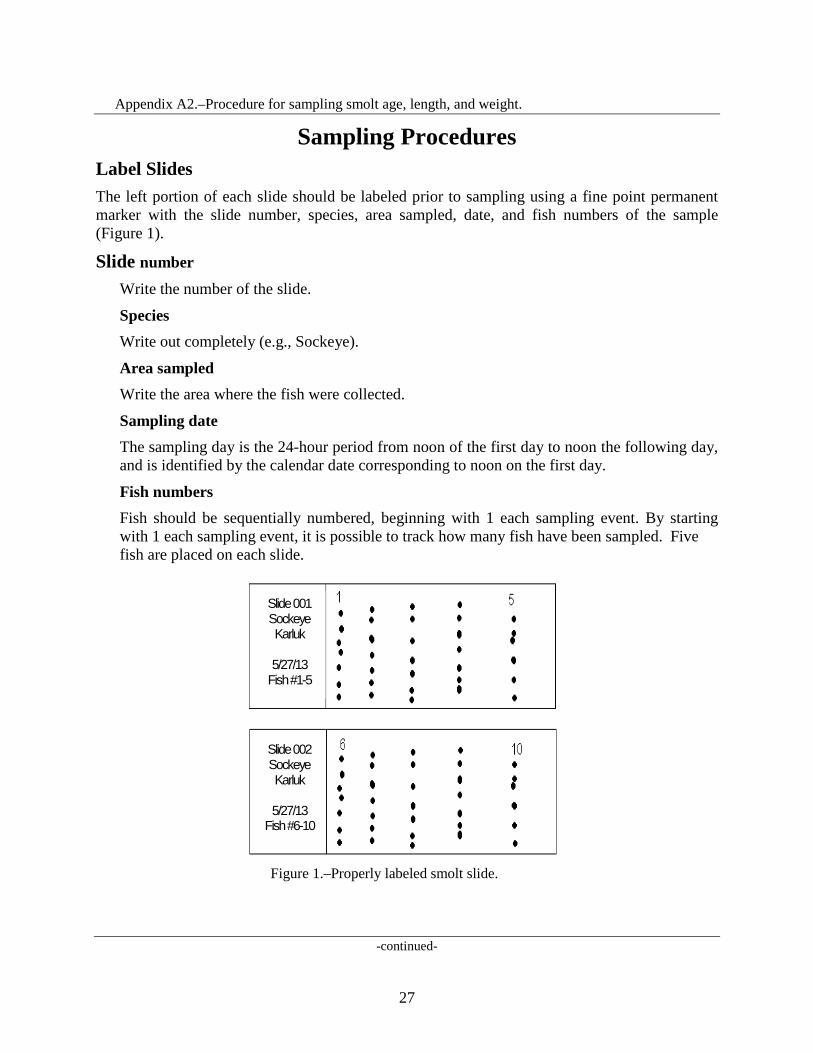
Sampling Procedures Label Slides The left portion of each slide should be labeled prior to sampling using a fine point permanent marker with the slide number, species, area sampled, date, and fish numbers of the sample (Figure 1).
Slide number Write the number of the slide.
Species Write out completely (e.g., Sockeye).
Area sampled Write the area where the fish were collected.
Sampling date The sampling day is the 24-hour period from noon of the first day to noon the following day, and is identified by the calendar date corresponding to noon on the first day.
Fish numbers Fish should be sequentially numbered, beginning with 1 each sampling event. By starting with 1 each sampling event, it is possible to track how many fish have been sampled. Five fish are placed on each slide.
Figure 1.–Properly labeled smolt slide.
-continued-
Slide 002 Sockeye Karluk
5/27/13
Fish #6-10
Slide 001 Sockeye Karluk
5/27/13
Fish #1-5
27
Appendix A2.–Page 2 of 10.
Sample ASAP Sample smolt as soon as possible after they are captured.
Mix anesthetizing solution Wearing latex gloves to prevent direct exposure to the anesthetic, dissolve a small amount (approximately of 1 g) of Tricane Methanesulfate (MS-222) and baking soda in about 2 L of cold water in a dish pan. The amount of anesthetic needed will vary depending on the water temperature, freshness of the chemical, and size of the smolt.
Set up recovery bucket Set up an additional bucket of water to be used as a recovery bucket. This bucket should be filled with fresh water, aerated, and covered to avoid stress on the fish.
Transport smolt to sampling area Transport smolt, using clean 5-gallon buckets, to the sampling area. Buckets containing smolt should be filled with fresh water, aerated, and covered to avoid stress on the fish. Fish can be placed into the bucket using a dip net, or by dipping the bucket into the live box.
Anesthetize smolt a few at a time Place a few smolt in the anesthetic solution until they become subdued to a point where they can no longer flex their axial musculature but can still ventilate their gills. The concentration of the solution should be such that it immobilizes the fish in 2–3 minutes.
Lightly dry preferred area After the fish are anesthetized, carefully remove a fish from the dish pan and gently pat dry with a paper towel.
Sample smolt Place the fish on its right side to sample the left side. Quickly and carefully take length and weight measurements, and remove 5–10 scales from the preferred area of the smolt using a scalpel (Figure 2). On salmon species, the preferred scale is located where a straight line between the posterior insertion of the dorsal fin and the anterior insertion of the anal fin crosses the second scale row dorsal to the lateral line. If scales are not present in this area then scales should be taken from the secondary location, which is the same area on the right side of the fish.
-continued-
28

Appendix A2.–Page 3 of 10.
Measure smolt from the tip of the snout to the fork of the tail.-
Figure 2.–Smolt with proper length measurement and preferred area highlighted.
Move smolt to recovery bucket Transfer sampled smolt from the sampling station to the recovery bucket. It is important to sample as quickly as possible and immediately place smolt into the recovery bucket to prevent mortality.
Align scales on slide Using the dissecting probe, line up and spread out the scales on the slide under the correct fish number (Figure 1).
Clean sampling supplies Wipe off the scalpel and dissecting probe to remove scales and slime before another smolt is sampled.
Continue sampling Continue sampling smolt until sampling goals are met, or all available smolt have been sampled. Depending on how long it takes to complete the sample, the water in all buckets (holding, recovery, and anesthetizing) may need to be refreshed.
Relesase smolt Once the sampled fish have recovered and are swimming normally in the recovery bucket, they should be released downstream of the trapping location.
-continued-
Preferred area
29
Appendix A2.–Page 4 of 10.
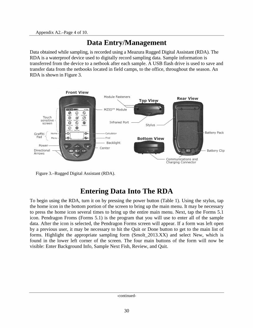
Data Entry/Management Data obtained while sampling, is recorded using a Meazura Rugged Digital Assistant (RDA). The RDA is a waterproof device used to digitally record sampling data. Sample information is transferred from the device to a netbook after each sample. A USB flash drive is used to save and transfer data from the netbooks located in field camps, to the office, throughout the season. An RDA is shown in Figure 3.
Figure 3.–Rugged Digital Assistant (RDA).
Entering Data Into The RDA To begin using the RDA, turn it on by pressing the power button (Table 1). Using the stylus, tap the home icon in the bottom portion of the screen to bring up the main menu. It may be necessary to press the home icon several times to bring up the entire main menu. Next, tap the Forms 5.1 icon. Pendragon Froms (Forms 5.1) is the program that you will use to enter all of the sample data. After the icon is selected, the Pendragon Forms screen will appear. If a form was left open by a previous user, it may be necessary to hit the Quit or Done button to get to the main list of forms. Highlight the appropriate sampling form (Smolt_2013.XX) and select New, which is found in the lower left corner of the screen. The four main buttons of the form will now be visible: Enter Background Info, Sample Next Fish, Review, and Quit.
-continued-
30

Appendix A2.–Page 5 of 10.
Table 1.–Buttons and icons addressed in the text.
Enter Background Info Background information must be entered at the start of each sampling event. A new day always constitutes a new sampling event, so it will be necessary to enter new background information typically once per sampling day. It is important to edit background information when any change in sampling information occurs. The following topics constitute sampling information. If information in one of the following categories changes, it is necessary to change the background information.
Species Select the appropriate species from the drop down list on the RDA.
Management Area Choose the relevant management area from the dropdown list. Samples collected from Kodiak Island statistical areas must have Kodiak selected as the proper management area.
Area Sampled Select the area that best represents where the fish were sampled, such as Ayakulik River, from the dropdown list.
Location ID (N/A for some areas) Enter the site where the fish being sampled are from. For Karluk Lake sockeye salmon smolt sampling, Site 1 is the outlet site and Site 2 is further downstream.
Location Type Indicate the type of area in which the fish were captured.
-continued-
31

Appendix A2.–Page 6 of 10.
Gear Type Select the type of gear in which the smolt were caught.
Date of Sample For smolt, the sampling day is the 24-hour period from noon of the first day to noon the following day, and is identified by the calendar date corresponding to noon on the first day.
Sampler Initials Enter the initials of the sampling crew (up to 3 persons). This can be done by writing in the box on the bottom of the screen, or by using the pop up keyboard.
Notes 1. When entering text, tap on the dot by the abc icon to bring up a keyboard. 2. To delete a character, place the stylus in the text box and draw a small straight line from
right to left.
Sample Next Fish: After entering background information, the RDA is ready to collect individual fish data. The Sample Next Fish button is used to enter the details of each fish sampled. It is not necessary to click on the Sample Next Fish button when entering the first fish of a new sample. After entering the background information, the form automatically knows to go to the sample next fish section of the form. As you continue to sample, simply tap Sample Next Fish or Next to enter individual fish data. This option is used when continuing to the next fish of a sample where no background information has changed. Fish data that is entered here is associated with the current background information logged. The following constitute fish data and should be entered for each fish.
Scale Slide (Card) Number Slides are numbered sequentially by date throughout the season starting with 1. A separate numbering sequence will be used for each species or major location change. Consult your crew leader for the current slide number. It is crucial to make sure the number written on the slide matches the slide (card) number entered into the RDA. The slide number will automatically advance to next number after five fish have been sampled.
Fish Number The fish number is a sequential numbering system that begins with the number 1 for each sampling event. This allows samplers to keep track of the number of fish sampled each day (or since the background was changed). By default, the fish number in the RDA will automatically advance after each fish is sampled.
-continued-
32
Appendix A2.–Page 7 of 10.
Length in mm Enter the length of the smolt from tip of snout to tail fork in millimeters (i.e., 108). If for some reason you do not collect a length measurement, enter 999.
Fin Clip and Genetics Select the Skip Fin Clip and Genetics button if appropriate. If sampling involves fin clips or genetics you can enter the optional fin clip and genetics information.
Sample Next Fish Select Sample Next Fish to continue sampling.
Review/Edit The review button can be a very useful tool during sampling. It can be used to ensure data being entered is accurate, or it can be used for editing fish data during a sample. The review portion of the form displays slide number, fish number, length, and weight. The most recently sampled fish appear first. To enter the review screen, tap on the Review button on the main screen of the form. After the data has been reviewed and edited, tap the Done button on the bottom right of the screen to return to the main screen of the form. If Sample Next Fish is selected after leaving the review screen, the auto-increment will continue as if the review screen was never entered.
Reviewing Data To review the last data entered, tap the Review button on the main screen of the form. Use the scroll bar on the right side of the screen to look at the fish that have been entered.
Editing Data If fish data needs to be edited, tap on it using the stylus. Tap on the Sample Next Fish button to go through the fish data that was previously entered for that fish. Changes can be made as needed. Buttons chosen prior to the review are highlighted with asterisks. After a fish has been edited, the main review screen appears. If a fish is accidently selected from the main review screen, click the button that has the slide#-fish# to return to the main review screen without going through the fish data. As mentioned above, tap Done to exit the review portion of the form and return to the main screen.
Quit When sampling is complete, tap Quit to exit the form.
-continued-
33
Appendix A2.–Page 8 of 10.
Data Management
After sampling is done for the day, the data must be backed up on the RDA itself and then transferred (by HotSync) to the netbook.
Backing up data After each sample the RDA should be backed up so that data is stored on both of the compact flash drives. Turn the RDA on, and tap the home icon in the bottom portion of the screen to bring up the main menu. Tap the CardBkup icon if it is present, and then the Backup Now button at the top left of the screen. The data will now be on both flash drives. If the RDA does not have a CardBkup icon, it will back up automatically.
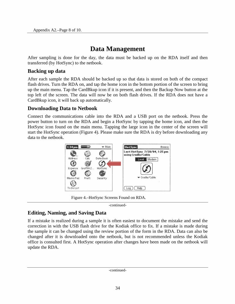
Downloading Data to Netbook Connect the communications cable into the RDA and a USB port on the netbook. Press the power button to turn on the RDA and begin a HotSync by tapping the home icon, and then the HotSync icon found on the main menu. Tapping the large icon in the center of the screen will start the HotSync operation (Figure 4). Please make sure the RDA is dry before downloading any data to the netbook.
Figure 4.–HotSync Screens Found on RDA.
-continued-
Editing, Naming, and Saving Data If a mistake is realized during a sample it is often easiest to document the mistake and send the correction in with the USB flash drive for the Kodiak office to fix. If a mistake is made during the sample it can be changed using the review portion of the form in the RDA. Data can also be changed after it is downloaded onto the netbook, but is not recommended unless the Kodiak office is consulted first. A HotSync operation after changes have been made on the netbook will update the RDA.
-continued-
34
Appendix A2.–Page 9 of 10.
To view data, HotSync the RDA and open Pendragon Forms Manager (a shortcut should be located to the right of the start menu) on the netbook. Select the form (Smolt_2013.XX), and click Edit/View under Data Functions on the right side of the window. All data will now be visible. Simply make the necessary minor changes here and exit out of the window to save. It is important to change the correct the numbers under the proper column which is where it is best to consult the Kodiak office. Hotsync the RDA to the netbook after any changes are made on the netbook to update the RDA with all changes.
After data has been edited and verified, a copy of the database will need to be exported from the Pendragon software and saved on the netbook. In Pendragon Forms Manager under Data Functions on the right side of the window, click To ASCII. Navigate to the folder in which the data is being saved. Type in the file name and then save. The file name should follow this format: Area_Sampled_Smolt_YYYYMMDD.csv (e.g., Afognak_River_Smolt20130614.csv). After saving, a window will pop up stating the file has been created. Each .csv file will contain all of the data that has been collected up to that point in the season. Do not edit or save the .csv file as an excel file or it will be difficult or impossible to upload the data into the database.
Transferring Data from Netbook onto USB Flash Drive Up to date data should be sent into the main office as often as possible (e.g., with the grocery plane). Insert a USB flash drive into an appropriate port on the netbook. Double click on MyComputer, which is found on the desktop of the netbook. Navigate to the folder where your data is saved and highlight the most recent file (determined by the date) by single clicking. With the file highlighted, click on edit at the top of the window and then copy. Open up MyComputer and double click on the USB flash drive (often called “Removable Disk”) found under the heading “Devices with Removable Storage.” Click on edit at the top of the window, and then paste. The .csv file that was copied earlier will appear in the window indicating it was copied to the flash drive. Exit out of all windows and single click on the safely remove hardware button on the bottom right corner of the desktop in the quick start menu. Click on “Safely remove USB Mass Storage Device.” A pop-up will verify that it is now safe to remove the flash drive from the system.
Powering the Netbook and RDA 1. The RDA can be charged with either the AC or DC powering options. It is the crew
leaders responsibility to keep it charged
2. The netbook can only be charged with the AC power adaptor, therefore plan accordingly for generator use. The charging light on the netbook is red when charging, and green when fully charged.
3. If there are powering problems, please contact the office immediately.
-continued-
35

Appendix A2.–Page 10 of 10.
Some Notes and Reminders 1. Connect the AC adaptor to the bottom of the communications cable to charge the RDA
batteries. If using the DC charger, connect the charger into the communications port.
2. If a mistake is noticed before moving onto the next fish, the previous button can be used to make changes in the RDA without having to go to the review screen or alter the data on the netbook.
3. Each length, weight, and scale must correspond to a single fish! It is the responsibility of the crew leader to be sure the data has been entered correctly.
4. Never put data from different dates onto one slide, and always enter new background information. Even if only one fish is sampled that day, enter new background information and begin with a new slide the next day.
5. Responsibility for accuracy lies first with the primary data collector(s) and finally with the crew leader. Sloppy or incomplete data or slides will be returned to individual collectors for correction.
6. Ensure that all equipment is well kept. Electronics should be stored in a clean safe place. The RDA must be completely dry before transferring data to the netbook. RDA batteries must be charged to make certain sampling is not hampered. It is the responsibility of the crew leader to make sure that all data is carefully examined and before returning it to their supervisor.
Troubleshooting Resetting the RDA If problems are encountered with the RDA, a soft reset can be done without losing data. To perform a soft reset hold the power and backlight button down together, and release at the same time. If a soft reset does not work, the office should be contacted about other options for resetting.
Hotsync Error Message HotSync message "Exceeded user storage space limit of 500KB in form 'Smolt_2013.XX'
1. Open Pendragon Forms Manager 2. Under Form Function click on "Properties" 3. Click on "Advanced Properties" 4. Click on the "Synchronization Tab" 5. Change the Storage Limit (KB) to 5000 instead of 500. 6. Click "OK" 7. Under Form Functions Click on "Distribute"
36

APPENDIX B. FISH PASS MAINTENANCE AND
OPERATION
37

Appendix B1.–Fish pass maintenance and operation.
Initial maintenance of the old fish pass should be completed prior to 1 June to ensure proper functioning of the facility. Maintenance consists of the following: 1. Inspect the fish passes for structural damage.
2. Install the modified I-beam supports on the diversion weir above the falls.
3. Clean the debris from the fish pass tanks.
4. Clean the fish pass entrance if necessary. The shiny surface may make some fish shy away from the entrance, if this occurs, add rocks to cover the aluminum.
5. Clear rocks and streambed materials from the entrance of the exit tank, channel, stop-log base of water control weir, and entrance tanks.
Fish pass (old) opening procedures include: 1. Insert wood drain plugs from the inside of the tanks into drain holes. Plugs should fit tightly,
so that internal tank water pressure holds the plug in place. Install the tank caps by screwing them on from the outside.
2. Position tank covers, and remove stop-logs slowly from exit tank. The bottom stop-log remains in place. Note that if stop-logs are removed rapidly moving gravel will be deposited into the tank.
3. Make sure no holes are present where fish could escape uncounted.
The fish pass should be operated so that the steep pass is about 3/4 full of water. This volume is necessary to attract sockeye salmon to the entrance tank and promote optimum fish passage. A water level of 1.8–1.9 feet should be maintained on the staff gauge by removing or placing stop-logs at the far end of the water control diversion (top of falls). At this level the old fish pass should be 3/4 full. Try to keep stop logs relatively level across the weir to prevent excessive erosion.
A vertical slot "door" should be placed at the entrance tank during the sockeye salmon run. This door should be checked daily during fish passage to assure it is completely down. It can open, inadvertently, when sockeye salmon hit against it. The opening space (23 cm) is needed to maintain velocity for fish attraction. The door can be opened to 1 foot (30 cm) at seasons end to further attract fish.
The fish pass should be checked daily for cover tightness and unobstructed water flow. Under no circumstances should obstructive materials be placed in the exit tank or steep passes. Make sure to remove any dead fish observed in the exit tank as soon as possible because dead fish will accumulate in the resting tanks making the end of season task of cleaning extremely unpleasant.
Do not let detergents or chemicals enter the fish pass water supply.
Post and maintain a “Keep off the fish pass” sign on the trail between the cabin and the fish pass and put up other signs directing visitor traffic to appropriate trails.
-continued-
38
Appendix B1.–Page 2 of 2.
Fish pass closing procedures (approximately 1 September): 1. Remove stop-logs and I-beam supports from the water control weir. Stack logs on the stream
bank and store the I-beams (well greased) in the tractor shed. Replace stop-logs in the exit tank, and visqueen as necessary to stop water flow between logs.
2. Remove all the drain caps by lightly tapping them from outside of the tanks, and store the plugs in the tractor shed. All water should be drained from the tanks. All residual materials within the tanks should be removed.
3. Remove the vertical slot door and replace it with a solid door to prevent unwanted animals from entering.
4. Inspect the fish pass and the facility for needed repairs, and list needed materials in the daily log/annual report. Also include fuel caches and propane so that we know what is left behind.
5. When the lower weir is removed, panels should be stored on the lower stream banks. Bolts on the weir should be tightened and replaced if necessary. Catwalk and stringer m
6. Materials should be inspected and replaced if required. Add lumber needs to the materials list.
39

40

APPENDIX C. SATELLITE TELEPHONE AND DISPATCH
INSTRUCTIONS
41

Appendix C1.–Satellite telephone and dispatch instructions.
The following information serves as a Policy Statement regarding the allowable uses of ADF&G satellite phones and Instructions on the proper method to successfully set up and operate the satellite phone system assigned to your camp.
These systems are not like standard telephones or cell phones, nor are they like a single side band or VHF radio. Communication is sent through the transmitter to low level satellites, then is beamed down to ground stations, either directly to another satellite phone system or to a switching station linked to standard telephone lines. As such, there is a much higher cost involved in operation than with standard telephone long distance or cell phone charges.
Under NO CIRCUMSTANCES may you use this satellite phone system for personal calls, unless, for each event, you have obtained direct and explicit permission from your supervisor. This does not mean that field crew leaders may grant permission for personal use of this phone. Only the project biologist may give you such permission. ANY DELIBERATE MISUSE OF THIS SYSTEM, SUCH AS MAKING UNAPPROVED, NON-EMERGENCY, OR PERSONAL CALLS, WILL RESULT IN DISCIPLINARY ACTION, WHICH MAY INCLUDE SUSPENSION OR DISCHARGE.
The primary purpose for having this satellite phone is for secure, reliable communications between remote field stations and ADF&G offices (Kodiak, Chignik, Cold Bay, Sand Point, or Port Moller), ADF&G research vessels (Resolution or K-Hi-C), Fish and Wildlife Protection vessels and offices, or other field camps that are similarly equipped. The secondary purpose is for your SAFETY. With these phones you are capable of directly dialing emergency services at any time of the day or night. It is essential that these phone systems are maintained in good working order, are fully charged or hooked to sufficient power at all times, and remain free for official or emergency use.
INSTRUCTIONS The portable sat phone unit must be charged with power. There is an internal battery pack, and a 12-volt adapter is available in order to hook the phone to a larger battery bank, that may in turn be recharged by generator or solar panels.
Turn the unit on using the power switch in the lower left corner. A green light, just above the switch, should come on indicating that the unit is sufficiently powered. If no light or a red light comes on, you will need to charge the unit, or attach it to your 12-volt battery bank via the appropriate connections.
The back, or top, of the briefcase-like unit is the antenna, and it must be oriented correctly in order to access the receiving satellite. The top of the case should be open and pointed in a general east-southeast direction. You must have a fairly clear line-of sight to the horizon in that direction; this unit will NOT work through walls or mountains. The angle of the antenna should be almost vertical; remember to lock the support arm that attaches the lid to the main body of the unit, along the right side.
-continued-
42
Appendix C1.–Page 2 of 3.
This system has two means for calling; a telephone-like handset (for dial in or dial out phone calls), and a push-to-talk microphone (for ‘dispatch’, unit to unit, calls). All calls made with the handset are billed per minute of use, at an expensive rate. All calls on the ‘AlaskaNet’ dispatch system, using the microphone, are essentially FREE.
When first turned on, the handset and microphone should become active, with the display panels on the top of the phone handset and microphone lighting up (one LED panel, hopefully the one on the handset, should read SLEEP). The display will show, after a few moments, whether a connection has been established with the satellite, and how strong the signal is (ex. B05 S 21). Turn the unit slightly, and raise or lower the lid/antenna slightly until the highest possible signal strength is indicated (normally above 20 but will work down to 8). Lock the lid/antenna in place and do not turn the unit again, until your communications are finished. Once a strong signal is acquired push the “*” button for 2 seconds. Wait until there is a “beep” and the LCD screen displays ’00:DN ??’, then dial the number.
Alaska Dispatch System Because all calls made on the dispatch system are FREE, this is the method of choice for using the satellite phone units. There are several ADF&G offices, many field camps, and two research vessels on the AlaskaNet dispatch system, as well as Fish and Wildlife Protection/State Troopers offices and vessels, plus many canneries, fishing vessels, and tenders. You should have received a 10–12 page directory with your phone.
First, make sure the unit is turned on, and that there is sufficient power. Set the unit up so that the signal strength is at the maximum for your location. You should see the signal strength on the microphone display (ex. B05 S 21), and the handset display should read SLEEP. Once a strong signal is acquired push the “*” button for 2 seconds. Wait until there is a “beep”.
On the microphone display, below the signal strength, there should be a query, ‘00:DN ??’. This is asking you to ‘dial’ in the 4-digit dispatch number that you wish to call. After you have entered the 4-digit dispatch number of the unit you wish to contact, hold in the microphone key and a connection will be made with the satellite, which will then try to connect with the dispatch number you punched in. IF a connection is made you will hear two beeps (“bird chirps”) and the microphone display will read SELF. While continuing to hold in the microphone key, call the station you wish to talk to. USE ALL THE SAME FORMALITIES AS WHEN CALLING ON A SSB RADIO. For example, say “Calling the ADF&G Kodiak Office, Calling the ADF&G Kodiak Office; this is Karluk Weir”. When you release the microphone key, the unit will beep again.
BE PATIENT. It will take some time for the signal to go up to the satellite, down to the number you called. It may take the other party some time to get to the microphone and respond (this is especially true for calls to the ADF&G office; supervisors have to walk down to the radio room to respond). When they respond, their 4-digit dispatch number (DN) will show on the microphone display. This is a private conversation, unlike the previous dispatch service.
-continued-
43
Appendix C1.–Page 3 of 3.
Just remember to be patient; wait until the other party stops speaking and you hear the unit beep (indicating that they are finished with this portion of their communication), the display should read SELF, and you may key microphone to talk. Then you must again wait for the other party to respond. If the other party is not there, they simply will not answer. If the satellite connection cannot be made, the display will read ‘Unable to Connect’ or ‘Not Available’.
Phone System DO NOT USE THE HANDSET TO PLACE CALLS UNLESS ABSOLUTELY NECESSARY. All calls made with the handset are billed per minute of use, at an expensive rate. Calls should only be made to supervisors, either when radio or dispatch contact is not possible or when a confidential message needs to be relayed. Calls are made by dialing out, almost like a standard telephone. Punch in the area code and telephone number, then PRESS SEND (button located in the upper right corner of the handset). Because there is a satellite relay, there will be a slight delay between when you speak and when the other party hears you, so be patient.
Note EVERY call in a phone logbook. The system will show you the amount of time you’ve used on the call, on the LED panel. Note the number called, the date, approximate time, and the length of the call (minutes and seconds). When the call is completed, you MUST push the END button (top right corner of handset buttons), otherwise the system will remain active and YOU will be billed for the time (at almost a dollar a minute). Remember, PRESS END.
If someone calls in to this unit, it will ring, like a standard telephone. Press the SEND button to start the conversation, but remember to PRESS END to finish the call. ADF&G is billed for all calls made using the handset, both the calls you dial out and any calls dialed in.
Assistance If the phone or dispatch system are not operating properly and you are not able to trouble shoot the issue there is a help line that can be called by dialing 611 on the phone system which will take you to technical support.
IN CASE OF EMERGENCY: If there is a medical emergency, or a real danger to life or health, IMMEDIATELY call the US Coast Guard Rescue Coordination Center at 800-478-5555. Be ready to tell them your name, exact location (Frazer cabin is located at 7°12.1’ N lat and 154°3.6’ W long) and the exact nature of your emergency. They may question you extensively, so be prepared. There are emergency doctors on-call that can advise you. After the call is completed, immediately call your supervisor, at work or at home, and relay the details of your experience. If there is an enforcement emergency, use the dispatch microphone to call the Kodiak office or the Alaska State Trooper, Fish and Wildlife Protection (DN 6370).
44
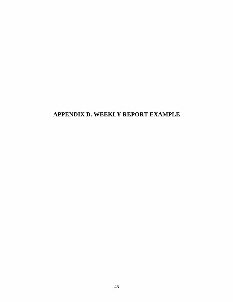
APPENDIX D. WEEKLY REPORT EXAMPLE
45
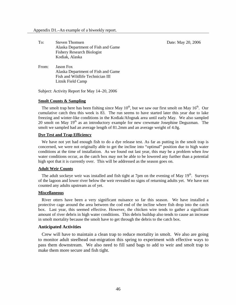
Appendix D1.–An example of a biweekly report.
To: Steven Thomsen Date: May 20, 2006 Alaska Department of Fish and Game
Fishery Research Biologist Kodiak, Alaska
From: Jason Fox
Alaska Department of Fish and Game Fish and Wildlife Technician III
Litnik Field Camp Subject: Activity Report for May 14–20, 2006 Smolt Counts & Sampling
The smolt trap here has been fishing since May 10th, but we saw our first smolt on May 16th. Our cumulative catch thru this week is 83. The run seems to have started later this year due to lake freezing and winter-like conditions in the Kodiak/Afognak area until early May. We also sampled 20 smolt on May 19th as an introductory example for new crewmate Josephine Deguzman. The smolt we sampled had an average length of 81.2mm and an average weight of 4.0g.
Dye Test and Trap Efficiency
We have not yet had enough fish to do a dye release test. As far as putting in the smolt trap is concerned, we were not originally able to get the incline into “optimal” position due to high water conditions at the time of installation. As we found out last year, this may be a problem when low water conditions occur, as the catch box may not be able to be lowered any further than a potential high spot that it is currently over. This will be addressed as the season goes on.
Adult Weir Counts
The adult sockeye weir was installed and fish tight at 7pm on the evening of May 19th. Surveys of the lagoon and lower river below the weir revealed no signs of returning adults yet. We have not counted any adults upstream as of yet.
Miscellaneous
River otters have been a very significant nuisance so far this season. We have installed a protective cage around the area between the cod end of the incline where fish drop into the catch box. Last year, this seemed effective. However, the chicken wire tends to gather a significant amount of river debris in high water conditions. This debris buildup also tends to cause an increase in smolt mortality because the smolt have to get through the debris to the catch box.
Anticipated Activities Crew will have to maintain a clean trap to reduce mortality in smolt. We also are going
to monitor adult steelhead out-migration this spring to experiment with effective ways to pass them downstream. We also need to fill sand bags to add to weir and smolt trap to make them more secure and fish tight.
46

APPENDIX E. TOTAL (100%) CAPTURE FEASIBLIITY
47
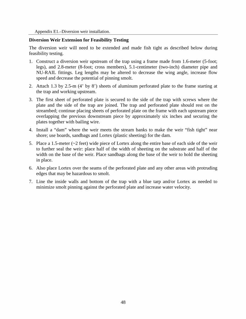
Appendix E1.–Diversion weir installation.
Diversion Weir Extension for Feasibility Testing The diversion weir will need to be extended and made fish tight as described below during feasibility testing.
1. Construct a diversion weir upstream of the trap using a frame made from 1.6-meter (5-foot; legs), and 2.8-meter (8-foot; cross members), 5.1-centimeter (two-inch) diameter pipe and NU-RAIL fittings. Leg lengths may be altered to decrease the wing angle, increase flow speed and decrease the potential of pinning smolt.
2. Attach 1.3 by 2.5-m (4’ by 8’) sheets of aluminum perforated plate to the frame starting at the trap and working upstream.
3. The first sheet of perforated plate is secured to the side of the trap with screws where the plate and the side of the trap are joined. The trap and perforated plate should rest on the streambed; continue placing sheets of perforated plate on the frame with each upstream piece overlapping the previous downstream piece by approximately six inches and securing the plates together with bailing wire.
4. Install a “dam” where the weir meets the stream banks to make the weir “fish tight” near shore; use boards, sandbags and Lortex (plastic sheeting) for the dam.
5. Place a 1.5-meter (~2 feet) wide piece of Lortex along the entire base of each side of the weir to further seal the weir: place half of the width of sheeting on the substrate and half of the width on the base of the weir. Place sandbags along the base of the weir to hold the sheeting in place.
6. Also place Lortex over the seams of the perforated plate and any other areas with protruding edges that may be hazardous to smolt.
7. Line the inside walls and bottom of the trap with a blue tarp and/or Lortex as needed to minimize smolt pinning against the perforated plate and increase water velocity.
48

Appendix E2.–Timed counts instructions.
Timed Counts If inundated with numbers of smolt you can choose to temporarily conduct timed counts or catch-weight methods to reduce mortality. If performing a mark-recapture test all smolt must still be examined for evidence of dye and tallied. Timed counts will also be used during feasibility testing.
Timed counts will be conducted every half-hour (30 minutes) from 2300 hours through 0500 hours. A 24-hour period from noon to noon, identified by the calendar date corresponding to the first noon, is a single enumeration day. Half-hour counts are from 1.0 minutes (minimum) to 8.0 minutes (maximum) in duration. The duration is dependent on the rate of smolt movement (e.g., the minimum time is used during large migrations and the maximum time during slower smolt movements.
1. At the beginning of a count, the gate on the counting trough is swung away from the operator, allowing smolt to drop into the counting basket submerged in the tank; use a stop-watch to time the collection of smolt in the counting basket.
2. At the end of the count, the gate is moved towards the operator, allowing smolt to bypass the counting basket. Record the count-time and enumerate the smolt from the counting basket, then release them down the pipeline.
3. Use the same procedures (number 1 and 2 above), if large smolt movements occur during the day (0500 to 2300 hours).
4. At the end of daily counting shift (~0500 hours), secure the gate in the open position, allowing smolt to fall into the counting basket. Cover the trough and catch basket with perforated plate to prevent smolt from jumping on to the floor.
5. Check the catch basket first thing in the morning (0900 hours); individually enumerate and release the smolt collected. Repeat this step just prior to noon when the counting day ends.
6. If smolt are spilling from the pipes at a slow rate, all smolt should be collected in the counting basket and counted individually.
49

50
Appendix E3.–Daily smolt 100% catch reporting form.
Date: Location:
Counting Muliple Timed Live Timed Live Other Live Timed Dead Timed Dead Other Dead TotalPeriod Time (30 Min. Count Count x Count Count Count x Count Estimate
(Military hrs) (Min:Sec) /Time) Multiple Multiple Live and Dead Remarks
Totals: Timed Live: 0 Timed Dead: 0 Timed Live&Dead: 0
Other Live: 0 Other Dead: 0 Other Live&Dead: 0
Total Live: 0 Total Dead: 0 Grand Total: 0
DAILY SMOLT 100% CATCH REPORTING FORM

51
Appendix E4.–Smolt 100% catch reporting summary form.
Timed Other (hand counts) Total Cumulative Percent DeadDate
Live Dead Live Dead Live Dead Live and Dead Live Dead Live and Dead Daily Cum.
SMOLT 100% CATCH REPORTING SUMMARY FORM
Appendix E5.–Catch-Weight instructions.
Catch-Weight If inundated with numbers of smolt you can choose to temporarily conduct timed counts or catch-weight methods to reduce mortality. Timed counts are the preferred method and catch-weight should only be used when the live box is too full to count by hand. If performing a mark-recapture test all smolt must still be examined for evidence of dye and tallied appropriately. Catch-weight counts will also be used during feasibility testing.
The catch-weight method estimates the number of smolt by using total weight and counts taken from a subsample from the live box and expands for total smolt weight in the live box. Using a hanging scale, weigh a sub sample (every 10th aggregate weight) and count the number of sockeye smolt in the sample. The number of other fish or smolt species must also be counted to adjust for species composition.
52
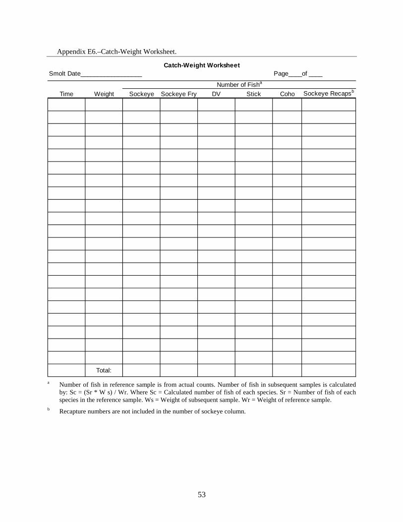
Appendix E6.–Catch-Weight Worksheet.
Smolt Date__________________ Page____of ____
Time Weight Sockeye Sockeye Fry DV Stick Coho Sockeye Recapsb
Total:
Catch-Weight Worksheet
Number of Fisha
a Number of fish in reference sample is from actual counts. Number of fish in subsequent samples is calculated
by: Sc = (Sr * W s) / Wr. Where Sc = Calculated number of fish of each species. Sr = Number of fish of each species in the reference sample. Ws = Weight of subsequent sample. Wr = Weight of reference sample.
b Recapture numbers are not included in the number of sockeye column.
53