foxboro evo™ process automation system - infi 90 infi90 documentation/foxia/31h2z29.pdf ·...
TRANSCRIPT
Foxboro Evo™ Process Automation System
Product Specifications
PSS 31H-2Z29
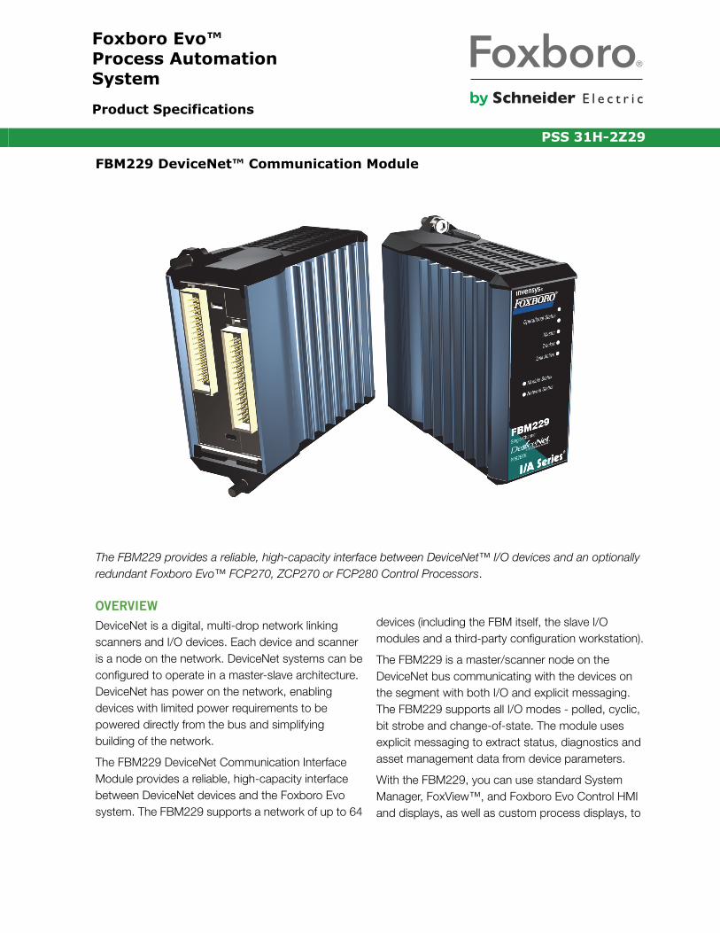
FBM229 DeviceNet™ Communication Module
The FBM229 provides a reliable, high-capacity interface between DeviceNet™ I/O devices and an optionally redundant Foxboro Evo™ FCP270, ZCP270 or FCP280 Control Processors.
OVERVIEW
DeviceNet is a digital, multi-drop network linking scanners and I/O devices. Each device and scanner is a node on the network. DeviceNet systems can be configured to operate in a master-slave architecture. DeviceNet has power on the network, enabling devices with limited power requirements to be powered directly from the bus and simplifying building of the network.
The FBM229 DeviceNet Communication Interface Module provides a reliable, high-capacity interface between DeviceNet devices and the Foxboro Evo system. The FBM229 supports a network of up to 64
devices (including the FBM itself, the slave I/O modules and a third-party configuration workstation).
The FBM229 is a master/scanner node on the DeviceNet bus communicating with the devices on the segment with both I/O and explicit messaging. The FBM229 supports all I/O modes - polled, cyclic, bit strobe and change-of-state. The module uses explicit messaging to extract status, diagnostics and asset management data from device parameters.
With the FBM229, you can use standard System Manager, FoxView™, and Foxboro Evo Control HMI and displays, as well as custom process displays, to
PSS 31H-2Z29Page 2
monitor the operating status of individual I/O devices and the health of the DeviceNet bus, including power supply status on the bus.
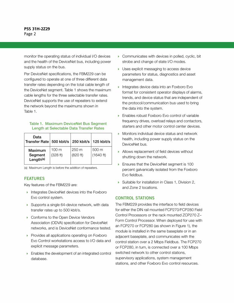
Per DeviceNet specifications, the FBM229 can be configured to operate at one of three different data transfer rates depending on the total cable length of the DeviceNet segment. Table 1 shows the maximum cable lengths for the three selectable transfer rates. DeviceNet supports the use of repeaters to extend the network beyond the maximums shown in Table 1.
FEATURES
Key features of the FBM229 are:
Integrates DeviceNet devices into the Foxboro Evo control system.
Supports a single 64-device network, with data transfer rates up to 500 kbit/s.
Conforms to the Open Device Vendors Association (ODVA) specification for DeviceNet networks, and is DeviceNet conformance tested.
Provides all applications operating on Foxboro Evo Control workstations access to I/O data and explicit message parameters.
Enables the development of an integrated control database.
Communicates with devices in polled, cyclic, bit strobe and change of state I/O modes.
Uses explicit messaging to access device parameters for status, diagnostics and asset management data.
Integrates device data into an Foxboro Evo format for consistent operator displays of alarms, trends, and device status that are independent of the protocol/communication bus used to bring the data into the system.
Enables robust Foxboro Evo control of variable frequency drives, overload relays and contactors, starters and other motor control center devices.
Monitors individual device status and network health, including power supply status on the DeviceNet bus.
Allows replacement of field devices without shutting down the network.
Ensures that the DeviceNet segment is 100 percent galvanically isolated from the Foxboro Evo fieldbus.
Suitable for installation in Class 1, Division 2, and Zone 2 locations.
CONTROL STATIONS
The FBM229 provides the interface to field devices for either the DIN rail mounted FCP270/FCP280 Field Control Processors or the rack mounted ZCP270 Z–Form Control Processor. When deployed for use with an FCP270 or FCP280 (as shown in Figure 1), the module is installed in the same baseplate or in an adjacent baseplate, and communicates with the control station over a 2 Mbps Fieldbus. The FCP270 or FCP280, in turn, is connected over a 100 Mbps switched network to other control stations, supervisory applications, system management stations, and other Foxboro Evo control resources.
Table 1. Maximum DeviceNet Bus Segment Length at Selectable Data Transfer Rates
Data Transfer Rate 500 kbit/s 250 kbit/s 125 kbit/s
Maximum Segment Length(a)
(a) Maximum Length is before the addition of repeaters.
100 m(328 ft)
250 m(820 ft)
500 m(1640 ft)
PSS 31H-2Z29Page 3
When the control station is a ZCP270, the FBM229 is installed in a 200 Series FBM system consisting of a Fieldbus Communications Module 100 (FCM100), the FBM229, and other FBM types.
The subsystem is connected to the ZCP270 via a 100 Mbps Ethernet network. For additional information on this subsystem, refer to Standard 200 Series Subsystem Overview (PSS 31H-2S200).
MODULAR BASEPLATE MOUNTING
In addition to the four-position baseplate shown in Figure 1, the FBM can be mounted on any of baseplates described in Standard 200 Series Baseplates (PSS 31H-2SBASEPLT).
The baseplate is either DIN rail mounted or rack mounted, and includes signal connectors for the FBMs, redundant independent dc power connections, and I/O cable connections.
The FBM229 is not powered by the DeviceNet segment. Rather, it sources power from the baseplate for its own operation and communication with the host control station. The FBM229 conforms to IEC 61158-2 and ISA S50.02 Physical Layer Standards as referenced to define, as a minimum, the signaling and electrical properties of a fieldbus device's Physical Layer interface.
The baseplate power is isolated from the voltage on the DeviceNet bus, which the FBM229 and other modules use for communication.
NOTEThe Foxboro Evo power supply is not used to power the DeviceNet segment. You will need to install one or more ODVA-compliant power supplies to power the DeviceNet segment. See ODVA publication PUB00027R1, Planning and Installation Manual: DeviceNet Cable System for details.
DEVICENET DROP
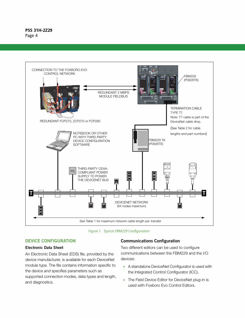
The FBM229 is connected to the DeviceNet segment via a DeviceNet specific termination cable (Type 7) and a termination assembly (TA), as shown in Figure 1. With this drop, the FBM229 operates as a scanner node on the network and complies with the DeviceNet Communication Adapter profile. See “TERMINATION ASSEMBLY” on page 6 for a description of the Type 7 cable and the TA.
DEVICENET TOPOLOGIES
A basic DeviceNet topology is shown in Figure 1, however, numerous other topologies can be employed. Refer to PUB00027R1, Planning and Installation Manual: DeviceNet™ Cable System (available at www.odva.org).
PSS 31H-2Z29Page 4
Figure 1. Typical FBM229 Configuration
DEVICE CONFIGURATION
Electronic Data Sheet
An Electronic Data Sheet (EDS) file, provided by the device manufacturer, is available for each DeviceNet module type. The file contains information specific to the device and specifies parameters such as supported connection modes, data types and length, and diagnostics.
Communications Configuration
Two different editors can be used to configure communications between the FBM229 and the I/O devices:
A standalone DeviceNet Configurator is used with the Integrated Control Configurator (ICC).
The Field Device Editor for DeviceNet plug-in is used with Foxboro Evo Control Editors.
PS
TT
DEVICENET NETWORK
REDUNDANT 2 MBPSMODULE FIELDBUS
CONNECTION TO THE FOXBORO EVOCONTROL NETWORK
NOTEBOOK OR OTHERPC WITH THIRD PARTYDEVICE CONFIGURATIONSOFTWARE
FBM229(P0926TK)
FBM229 TA(P0926TE)
TERMINATION CABLETYPE T7Note: T7 cable is part of the DeviceNet cable drop.
(See Table 2 for cable
lengths and part numbers)
See Table 1 for maximum network cable length per transfer
REDUNDANT FCP270, ZCP270 or FCP280
(64 nodes maximum)
THIRD-PARTY ODVA-COMPLIANT POWERSUPPLY TO POWERTHE DEVICENET BUS
PSS 31H-2Z29Page 5
Both editors extract device information from the EDS file, and enable you to specify I/O mode and data lengths for each device type to be used in the system. The configuration data is then downloaded to the FBM229 for each device instance.
Refer to Implementing a DeviceNet Network on the I/A Series® System (B0750CH) for additional information on I/A Series tools and editors for configuring and maintaining DeviceNet segments.
Device Parameter Configuration
The system requires a third-party configuration tool for device parameterization. The recommended tool is Rockwell Automation’s RSNetWorx™ for DeviceNet (Version 8.x), which was used in the development and testing of the FBM229. However, any ODVA-compliant configuration tool can be used.
FBM CAPACITY
Per ODVA specifications, the DeviceNet segment can have up to 64 drops, including the FBM229 master, slave I/O devices and a workstation with third-party configuration software.
For each device on the network, the FBM229 supports up to 250 bytes of I/O input data and up to 250 bytes of I/O output data.
The host FCP270/ZCP270 can make up to 1,000 connections to the I/O data being accessed (read or written) by each FBM229 over its DeviceNet segment. A connection may be to:
An analog input or output value (integer or floating point)
A string input or output
A single digital input or output value
Multiple digital input or output values (packed in groups of up to 32 digital points per connection).
An Foxboro Evo control station can access up to 1,000 analog I/O values, or 32,000 digital I/O values, or a combination of digital, analog, and string I/O, via the FBM229.
The FBM229 supports the Distributed Control Interface (DCI) block set that enables the control station to access device I/O data and explicit messaging for periodic parameter access.
For the complete specification of the number of devices supported versus maximum I/O per device, refer to the following documents:
Field Control Processor 270 (FCP270) Sizing
Guidelines and Excel® Workbook (B0700AV)
Z-Module Control Processor 270 (ZCP270) Sizing Guidelines and Excel Workbook (B0700AW)
Field Control Processor 280 (FCP280) Sizing
Guidelines and Excel® Workbook (B0700FY)
Implementing a DeviceNet™ Network on the I/A Series System (B0750CH).
NOTEThe performance numbers presented in this section relate only to the capability of the FBM229 itself, and do not take into account loading on the control station from other FBMs.
COMPACT DESIGN
The FBM229 has a compact design, with a rugged extruded aluminum exterior for physical and electrical protection of the circuits. Enclosures specially designed for mounting of the FBMs provide various levels of environmental protection, up to harsh environments per ISA Standard S71.04.
The module can be removed or replaced without removing field device termination cabling, power, or communications cabling.
PSS 31H-2Z29Page 6
VISUAL INDICATORS
Light-emitting diodes (LEDs) incorporated into the front of the module provide visual indication of the module’s operational status and the communication activity on the DeviceNet bus. The indicators include
the two standard DeviceNet green/red LEDs that indicate module and network status. Additionally, green and red LEDs indicate the operational status of the FBM229 itself and an intermittent amber LED shows communication activity on the DeviceNet bus.
TERMINATION ASSEMBLY
Overview
Field I/O signals connect to the FBM229 via the DIN rail mounted passive Termination Assembly (TA) (p/n P0962TE). The TA’s base is constructed of a rugged fire-retardant Polyamide material.
The TA and its associated termination cable provide feed-through connection between DeviceNet compliant field devices and the FBM229.
The TA includes two LEDs. A green one indicates there is CAN/network power and the polarity is correct. A red LED indicates that there is CAN/network, but that the polarity is incorrect.
The DIN rail mounted TA connects to the Modular Baseplate by means of a removable termination cable. The cable is available in a variety of lengths)
(Table 2), up to 5.0 meters (16.4 feet). The maximum TA-to-FBM cable length is limited so that the FBM drop on the DeviceNet segment is within the 6.0 meter maximum specified in the DeviceNet standard.
Features
Key features include:
Combination foot that supports 32 or 35 mm DIN rail mounting
Standard open 5-pin connector for connection to the DeviceNet segment
Type 7 cable and the TA form a DeviceNet compliant drop on the segment
LEDs indicate CAN/network power and polarity.
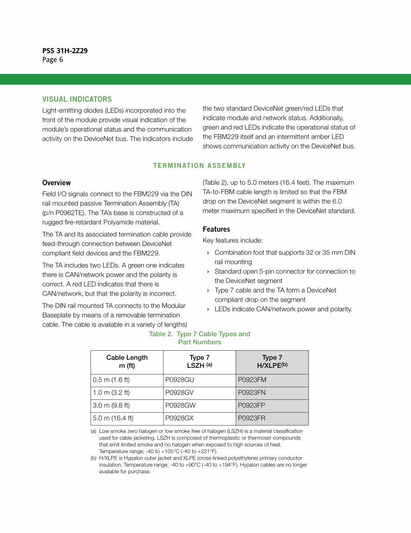
Table 2. Type 7 Cable Types andPart Numbers
Cable Lengthm (ft)
Type 7LSZH (a)
Type 7H/XLPE(b)
0.5 m (1.6 ft) P0928GU P0923FM
1.0 m (3.2 ft) P0928GV P0923FN
3.0 m (9.8 ft) P0928GW P0923FP
5.0 m (16.4 ft) P0928GX P0923FR
(a) Low smoke zero halogen or low smoke free of halogen (LSZH) is a material classification used for cable jacketing. LSZH is composed of thermoplastic or thermoset compounds that emit limited smoke and no halogen when exposed to high sources of heat. Temperature range; -40 to +105°C (-40 to +221°F).
(b) H/XLPE is Hypalon outer jacket and XLPE (cross-linked polyethylene) primary conductor insulation. Temperature range; -40 to +90°C (-40 to +194°F). Hypalon cables are no longer available for purchase.
PSS 31H-2Z29Page 7
FUNCTIONAL SPECIFICATIONS
DeviceNet CommunicationsThe FBM229 operates as a DeviceNet master/scanner using DCI blocks and I/O messaging in polled, cyclic, bit strobe and change of state modes for control data. The DCI blocks can also be used with explicit messaging to read device parameters for status, diagnostics and asset management.BUS CHARACTERISTICS
GeneralController Area Network (CAN) protocol as specified by ODVA for DeviceNet networks.Data Transfer Rate (Baud Rate)Three selectable speeds: 125, 250 and 500 kbit/sec depending on network length (see Table 1 on page 2)Maximum Allowable Bus LengthUp to 500 m (1,640 ft) at 125 kbit/sec without repeaters (see Table 1 on page 2)Maximum TA Cable Length, FBM229 to TA5.0 m (16.4 ft). As a DeviceNet drop, maximum cable length between the FBM229 and the DeviceNet trunk is 6.0 meters, per ODVA specificationsMaximum Number of Devices on a Bus64, including the FBM229, slave I/O devices and a workstation with a third-party configuration tool, per ODVA specifications.
NOTEThe TYPE 7 cable between the FBM229 and the TA is a permanently attached drop-line, and needs to be taken into account when calculating the complete drop-line from the DeviceNet trunk and the FBM229 module.
FBM229 Bus IsolationThe FBM’s fieldbus connection to the host CP270 or CP280 is galvanically isolated from the DeviceNet bus. The fieldbus is referenced to earth (ground). The FBM229 can withstand, without damage, a potential of 600 V ac applied for one minute between the network and earth.
CAUTION
This does not imply that the channels are intended for permanent connection to voltages of these levels. Exceeding the limits for input voltages, as stated elsewhere in this specification, violates electrical safety codes and may expose users to electric shock.
Conformance to DeviceNet StandardsThe FBM229 conforms to the Open Device Vendors Association (ODVA) specification for DeviceNet networks, and is DeviceNet conformance tested.
FBM229 Power Requirements
INPUT VOLTAGE RANGE
24 V dc +5%, -10%CONSUMPTION
6.0 W (maximum)HEAT DISSIPATION
6.0 W (maximum)
PSS 31H-2Z29Page 8
FUNCTIONAL SPECIFICATION(CONTINUED)
Regulatory Compliance
ELECTROMAGNETIC COMPATIBILITY (EMC)
European EMC Directive 2004/108/ECMeets: EN 50081-2 Emission standard
EN 50082-2 Immunity standard EN 61326 EMC Standard (Industrial
Levels)CISPR 11, Industrial Scientific and Medical (ISM) Radio-frequency Equipment - Electromagnetic Disturbance Characteristics - Limits and Methods of Measurement Meets: Class A LimitsIEC 61000-4-2 ESD ImmunityContact 4 kV, air 8 kVIEC 61000-4-3 Radiated Field Immunity10 V/m at 80 to 1000 MHzIEC 61000-4-4 Electrical Fast Transient/Burst Immunity2 kV on I/O, V dc power and communication linesIEC 61000-4-5 Surge Immunity2 kV on ac and dc power lines;1 kV on I/O and communication linesIEC 61000-4-6 Immunity to Conducted Disturbances Induced by Radio-frequency Fields3 V (rms) at 150 kHz to 80 MHz on I/O, V dc power and communication linesIEC 61000-4-8 Power Frequency Magnetic Field Immunity30 A/m at 50 and 60 Hz
PRODUCT SAFETY
Underwriters Laboratories (UL) for U.S. and CanadaUL/UL-C listed as suitable for use Class I, Groups A-D; Division 2; temperature code T4 enclosure based systems. These modules are also UL and UL-C listed as associated apparatus for supplying non-incendive communication circuits for Class I, Groups A-D hazardous locations when connected to specified Foxboro Evo processor modules as described in the Standard and Compact 200 Series Subsystem User’s Guide (B0400FA). Communications circuits also meet the requirements for Class 2 as defined in Article 725 of the National Electrical Code (NFPA No.70) and Section 16 of the Canadian Electrical Code (CSA C22.1). Conditions for use are as specified in the Standard and Compact 200 Series Subsystem User’s Guide (B0400FA).European Low Voltage Directive 2006/95/EC and Explosive Atmospheres (ATEX) Directive 94/9/ECCENELEC (DEMKO) certified for use in Zone 2 enclosures and certified as associated apparatus for supplying non-incendive field circuits for Zone 2, Group IIC, potentially explosive atmospheres when connected as described in the Standard and Compact 200 Series Subsystem User’s Guide (B0400FA).
Calibration RequirementsCalibration of the module and termination assembly is not required.
PSS 31H-2Z29Page 9
ENVIRONMENTAL SPECIFICATIONS(1)
Operating
TEMPERATURE
FBM229-20 to +70°C (-4 to +158°F)Termination Assembly-20 to +70°C (-4 to +158°F)
RELATIVE HUMIDITY
5 to 95% (noncondensing)ALTITUDE
-300 to +3,000 m (-1,000 to +10,000 ft)
Storage
TEMPERATURE
-40 to +85°C (-40 to +185°F)RELATIVE HUMIDITY
5 to 95% (noncondensing)
ContaminationSuitable for use in Class G3 (Harsh) environments as defined in ISA Standard S71.04, based on exposure testing according to EIA Standard 364-65, Class III
Vibration7.5 m/S2 (0.75 g) from 5 to 500 Hz
PHYSICAL SPECIFICATIONS
Mounting
MODULE
The FBM229 mounts on a Modular Baseplate. The Modular Baseplate can be mounted horizontally or vertically on a DIN rail, or mounted horizontally in a 19-inch rack using a mounting kit. Refer to Standard 200 Series Baseplates (PSS 31H-2SBASEPLT) for details.TERMINATION ASSEMBLY
The TA accommodates multiple DIN styles including 32 mm (1.26 in) and 35 mm (1.38 in) rails.
Weight
MODULE
284 g (10 oz) approximate
Dimensions
MODULE
HEIGHT102 mm (4.0 in)114 mm (4.5 in) including mounting lugsWIDTH45 mm (1.75 in)DEPTH104 mm (4.11 in)
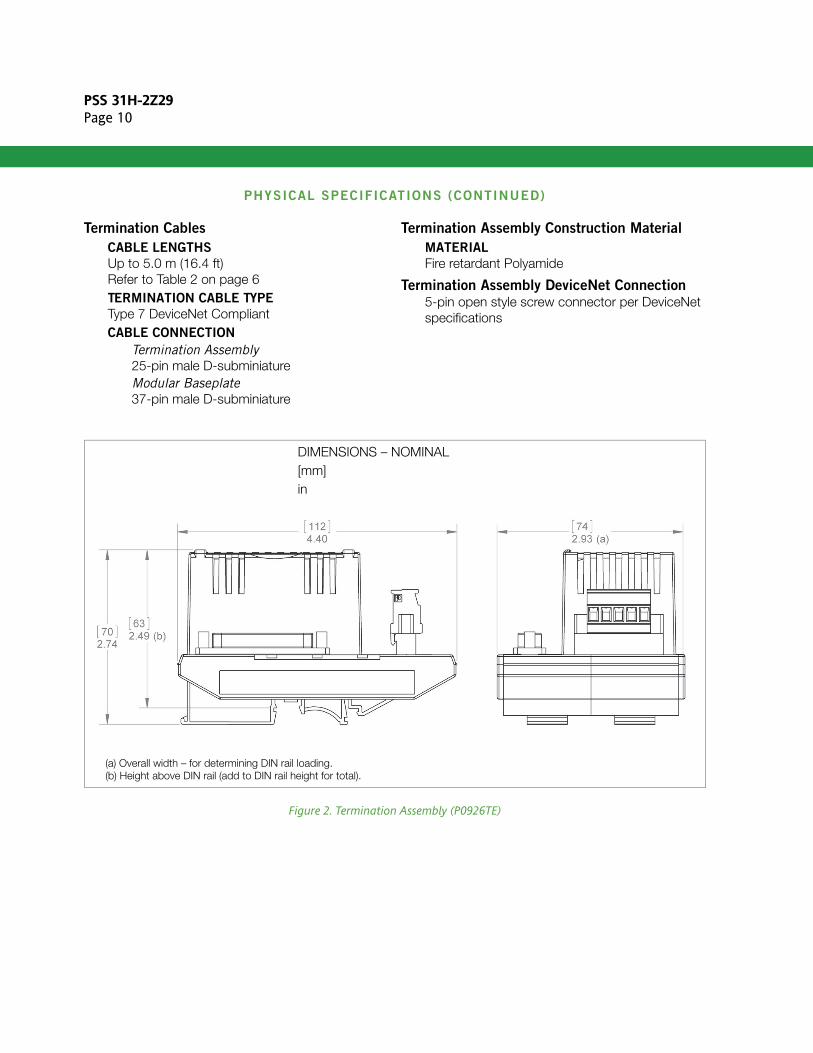
TERMINATION ASSEMBLY
See Figure 2 on page 10
Part Numbers
FBM229MODULE
P0926TKTERMINATION ASSEMBLY
P0926TE
Indicators Mounted on the Front of the FBM
OPERATIONAL STATUS
Red and green light-emitting diodes (LEDs)DEVICENET LINK STATUS
1 intermittent amber LED indicates communications activityDEVICENET MODULE STATUS
Green/red LED indicates FBM229 status as a DeviceNet moduleDEVICENET NETWORK STATUS
Green/Red LED indicates the status of DeviceNet busOTHER
2 amber LEDs (Master and Tracker) are reserved for future use
Indicators Mounted on TAGreen LED indicates when there is CAN/network power and correct polarityRed LED indicates when there is CAN/network power and incorrect polarity
(1) The environmental limits of this module may be enhanced by the type of enclosure containing the module. Refer to the applicable Product Specification Sheet (PSS) which describes the specific type of enclosure that is to be used.
PSS 31H-2Z29Page 10
PHYSICAL SPECIFICATIONS (CONTINUED)
Termination Cables
CABLE LENGTHS
Up to 5.0 m (16.4 ft)Refer to Table 2 on page 6TERMINATION CABLE TYPE
Type 7 DeviceNet CompliantCABLE CONNECTION
Termination Assembly25-pin male D-subminiatureModular Baseplate37-pin male D-subminiature
Termination Assembly Construction Material
MATERIAL
Fire retardant Polyamide
Termination Assembly DeviceNet Connection5-pin open style screw connector per DeviceNet specifications
Figure 2. Termination Assembly (P0926TE)
(a) Overall width – for determining DIN rail loading.(b) Height above DIN rail (add to DIN rail height for total).
DIMENSIONS – NOMINAL[mm]in
PSS 31H-2Z29Page 11
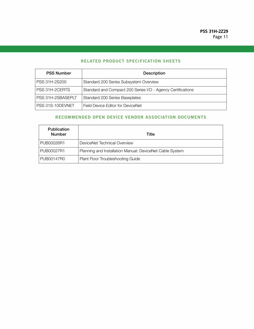
RELATED PRODUCT SPECIFICATION SHEETS
RECOMMENDED OPEN DEVICE VENDOR ASSOCIATION DOCUMENTS
PSS Number Description
PSS 31H-2S200 Standard 200 Series Subsystem Overview
PSS 31H-2CERTS Standard and Compact 200 Series I/O - Agency Certifications
PSS 31H-2SBASEPLT Standard 200 Series Baseplates
PSS 31S-10DEVNET Field Device Editor for DeviceNet
Publication Number Title
PUB00026R1 DeviceNet Technical Overview
PUB00027R1 Planning and Installation Manual: DeviceNet Cable System
PUB00147R0 Plant Floor Troubleshooting Guide

PSS 31H-2Z29Page 12
Invensys Systems, Inc10900 Equity DriveHouston, TX 77041United States of Americahttp://www.invensys.com
Global Customer SupportInside U.S.: 1-866-746-6477Outside U.S.: 1-508-549-2424 Website: https://support.ips.invensys.com
Copyright 2014 Invensys Systems, Inc. All rights reserved. Invensys is now part of Schneider Electric.
Invensys, Foxboro and Foxboro Evo are trademarks owned by Invensys Limited, its subsidiaries and affiliates.All other trademarks are the property of their respectiveowners.
MB 031 1114