foxboro invensys
DESCRIPTION
DocumentTRANSCRIPT
B0750AD
Rev EMay 6, 2011
Foxboro® Control Software
Access Manager User’s Guide
All rights reserved. No part of this documentation shall be reproduced, stored in a retrieval system, or transmitted by any means, electronic, mechanical, photocopying, recording, or otherwise, without the prior written permission of the Invensys Systems, Inc. No copyright or patent liability is assumed with respect to the use of the information contained herein. Although every precaution has been taken in the preparation of this documentation, the publisher and the author assume no responsibility for errors or omissions. Neither is any liability assumed for damages resulting from the use of the information contained herein.
The information in this documentation is subject to change without notice and does not represent a commitment on the part of Invensys Systems, Inc. The software described in this documentation is furnished under a license or nondisclosure agreement. This software may be used or copied only in accordance with the terms of these agreements.
© 2007-2011 Invensys Systems, Inc. All Rights Reserved.
Trademarks
Invensys, ArchestrA, Alarm Logger, ActiveFactory, FactorySuite, FactorySuite A2, InSQL, InFusion, InTouch, I/A Series, the Invensys logo, Foxboro, WindowMaker, and Wonderware are trademarks of Invensys plc, its subsidiaries and affiliates.
All other brand names may be trademarks of their respective owners.
iii
Contents
Contents..............................................................iii
Before You Begin ..............................................vii
Foxboro Control Software Access Manager ........................................ vii
Revision Information........................................................................... viii
Reference Documents ........................................................................... ixFCS Documentation .......................................................................... ixI/A Series Software Documentation .................................................. ixWonderware Documentation .............................................................. x
I/A Series Galaxy Browser..................................1
Accessing the I/A Series Galaxy Browser ............................................. 1From Framer Software........................................................................ 1From WindowMaker Software ........................................................... 2From the FCS Configuration Tools .................................................... 2
I/A Series Browser Tab Components ..................................................... 4I/A Configuration Pane....................................................................... 6Search View........................................................................................ 7Parameter Pane ................................................................................... 8DI & Extensions View...................................................................... 12Extensions Group ............................................................................. 13Value Field ........................................................................................ 14
Browser Cache Files............................................................................. 15
I/A Series Device Integration Objects..............19
Contents................................................................................................ 19
Installation............................................................................................ 20
I/A Series Device Integration Object Data Flow ................................. 20I/A Series Device Integration Object and Assignment..................... 22Configuring the I/A Series Device Integration Object ..................... 22Deploying I/A Series Device Integration Objects ............................ 27Accessing I/A Series Data ................................................................ 28I/A Series DI Object Informational Attributes ................................. 29Tags with $tag$ Prefix ...................................................................... 31DI Object Logs ................................................................................. 32Error Code Mapping......................................................................... 33
Access Manager User’s Guide – B0750AD Rev E
iv Contents
I/A Series OPC Device Integration Object Data Flow .........................34I/A Series OPC Device Integration Object Import and Assignment.35Configuring the I/A Series OPC Device Integration Object .............36IADAS User-Configurable Attribute Initialization ...........................45Accessing I/A Series Data .................................................................52Transactions and Subscriptions .........................................................53Commands.........................................................................................53System Items .....................................................................................54Tag Items ...........................................................................................57DI Object Logs ..................................................................................57
Extensions .............................................................................................58Summary of Tag Extensions Restrictions..........................................60Access Extensions .............................................................................63Frequency Extensions........................................................................64Data Extensions .................................................................................68Packing Extensions............................................................................71
I/A Series History Provider...............................73
I/A Series History Provider Installation................................................74
Wonderware Historian Installation .......................................................76Hardware Requirements ....................................................................76
Configuring Historian Collectors..........................................................76
Configuring the I/A Series History Provider ........................................78Operating History Object Editor .......................................................78Designating a Wonderware Historian Server ....................................80Collecting Platform and Application Engine Statistics .....................81Redundant History.............................................................................82
Configuring Historian Connections ......................................................84
Starting and Stopping the Wonderware Historian.................................86
Verifying History Storage .....................................................................87
History Object Log flags.......................................................................88
I/A Series Alarm Provider .................................91
Alarm Provider Components ................................................................92
Redeploying Alarm Provider ................................................................92
Alarm Provider Configuration ..............................................................93AppA Configuration for Alarm Providers.........................................93Process Alarm Database Tab .............................................................93Alarm Recovery.................................................................................95System Alarms ..................................................................................96Alarm Logging Configuration...........................................................97
Galaxy Sync Service .........................................99
Sync Service Components .................................................................100
Access Manager User’s Guide – B0750AD Rev E
Contents v
Sync Service Features ........................................................................ 100
Refreshing the History and Security Database................................... 101
Custom Configuration ........................................................................ 102Default Security Classification Configuration ............................... 102Galaxy Sync Service Configuration ............................................... 103Sync Agent Configuration .............................................................. 103
Galaxy Sync Service Utility............................................................... 104Stopping and Starting the Galaxy Sync Service ............................. 104Management Tab Set ...................................................................... 105Configuration Tab Set..................................................................... 108History and Security Configuration Without Using FCS Configuration Tools .........................................................................112
I/A Series Security Provider ...........................119
Introduction ........................................................................................ 120
Security Information Distribution ...................................................... 120
Using Write Access Security.............................................................. 121
Security Database............................................................................... 121
Enabling Security ............................................................................... 121
ArchestrA OPC Quality Word.........................123
Index ................................................................129
Access Manager User’s Guide – B0750AD Rev E

vi Contents
Access Manager User’s Guide – B0750AD Rev E
vii
Before You Begin
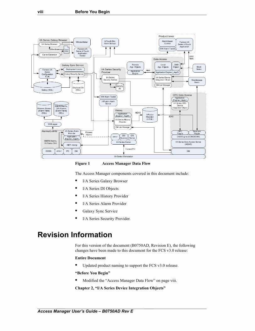
Foxboro Control Software Access ManagerThis document summarizes the functions, features, the ways and means of using the Foxboro® Control Software (FCS) Access Manager Suite of programs. The programs provide infrastructure integration with I/A Series® system real-time data and messaging for real-time data read-write access for process variables, historical data and process system alarms. FCS Access Manager includes optional parameter-level security and special components to use I/A Series services such as Object Manager (OM). The data flow diagram in Figure 1 identifies the FCS Access Manager Subsystems for Alarms, Data, History, and Security.
Access Manager User’s Guide – B0750AD Rev E
viii Before You Begin
Figure 1 Access Manager Data Flow
The Access Manager components covered in this document include:
• I/A Series Galaxy Browser
• I/A Series DI Objects
• I/A Series History Provider
• I/A Series Alarm Provider
• Galaxy Sync Service
• I/A Series Security Provider.
Revision InformationFor this version of the document (B0750AD, Revision E), the following changes have been made to this document for the FCS v3.0 release:
Entire Document
• Updated product naming to support the FCS v3.0 release.
“Before You Begin”
• Modified the “Access Manager Data Flow” on page viii.
Chapter 2, “I/A Series Device Integration Objects”
Access Manager User’s Guide – B0750AD Rev E
Before You Begin ix
• Removed duplicate entry from Table 2-11, “Extension Summary,” on page 59.
• Modified the “I/A Series Device Integration Object Editor General Tab Attributes” on page 23.
• Added information for “I/A Series Device Integration Object Editor General Tab Attributes” on page 23.
Chapter 3, “I/A Series History Provider”
• Modified the “I/A Series History Provider Data Flow” on page 73.
• Added a new section, “History Object Log flags” on page 88.
Chapter 4, “I/A Series Alarm Provider”
• Modified the “I/A Series Alarm Provider Data Flow” on page 91.
Chapter 5, “Galaxy Sync Service”
• Modified the “Galaxy Sync Service Data Flow” on page 99.
Chapter 6, “I/A Series Security Provider”
• Modified the “I/A Series Security Provider Data Flow” on page 119.
Reference DocumentsThe following sections provide FCS reference documents, I/A Series system documents and Wonderware® software reference documents.
FCS DocumentationRefer to the following documents for specific information about related FCS Configuration Tools and Editors:
• Foxboro Control Software Block Configurator User’s Guide (B0750AH)
• Foxboro Control Software Deployment Guide (B0750BA)
• Foxboro Control Software Control Database Deployment User’s Guide (B0750AJ)
• Foxboro Control Software Installation Guide (B0750RA)
• Foxboro Control Software Window Construction User’s Guide (B0750AS)
• Foxboro Control Software InTouch Application User’s Guide (B0750AQ)
• Foxboro Control Software Framer and Alarm Management User’s Guide (B0750AR)
I/A Series Software DocumentationRefer to the following I/A Series system documents for additional information on the I/A Series Object Manager and blocks and compounds:
• Integrated Control Block Descriptions (B0193AX)
• Object Manager Calls (B0193BC)
Access Manager User’s Guide – B0750AD Rev E
x Before You Begin
Wonderware DocumentationFor additional information about InTouch® software, the Wonderware Historian, and other ArchestrA® components, refer to the following Wonderware documents:
• Historian Client User's Guide
• InTouch Alarm and Events Guide
• InTouch Application Management and Extension Guide
• InTouch ArchestrA Integration Guide
• InTouch Concepts and Capabilities Guide
• InTouch Data Management Guide
• InTouch Documentation Guide
• InTouch HMI Documentation Addendum
• InTouch Protocol Guide
• InTouch Scripting and Logic Guide
• InTouch Smart Symbols Guide
• InTouch Supplementary Components User's Guide
• InTouch Visualization Guide
Access Manager User’s Guide – B0750AD Rev E
1
C H A P T E R 1
I/A Series Galaxy Browser
This chapter discusses the operation of the I/A Series Galaxy Browser, that identifies the available I/A Series compound and block parameters in a galaxy database. The browser is used to configure references to the I/A Series parameters for FCS InTouch application displays, and for application objects being configured with FCS Configuration Tools.
The I/A Series Galaxy Browser appears as a tab in the Galaxy Browser application. The tab identifies compounds, strategies, and blocks in a galaxy configuration. Other objects in the galaxy are displayed in the Attribute Browser tab.
Contents
• Accessing the I/A Series Galaxy Browser
• I/A Series Browser Tab Components
• Browser Cache Files
Accessing the I/A Series Galaxy BrowserYou can use the I/A Series Galaxy Browser for configuration from the FCS InTouch application (Framer or WindowMaker(TM) software) and from FCS Configuration Tools.
From Framer SoftwareThe I/A Series Galaxy Browser can be opened in FCS InTouch Application Framer software when a navigation set key or an annunciator key is selected in the main pane, to which a tag can be assigned. This is discussed in “Adding Process Graphic Windows to Navigation Sets” and “Adding Process Graphic Windows to Annunciators” in Foxboro Control Software Framer and Alarm Management User’s Guide (B0750AR).
Before the Framer software can open the Browser, you must specify the galaxy database location on the network, as discussed in “Identifying the Galaxy Database” in Foxboro Control Software Framer and Alarm Management User’s Guide (B0750AR).
Access Manager User’s Guide – B0750AD Rev E
2 1. I/A Series Galaxy Browser
From WindowMaker SoftwareThe I/A Series Galaxy Browser can be opened within WindowMaker software to assign tags to strings within InTouch software process graphic windows.
The WindowMaker software cannot recognize the existence of the I/A Series Galaxy Browser initially. You must enable the browser within the WindowMaker software, as discussed in “Configure InTouch to Use Galaxy as a Remote Tag Source” in the InTouch Documentation.
Note The InTouch Documentation refers to the Galaxy Browser as the Tag Browser.
From the FCS Configuration ToolsThe I/A Series Galaxy Browser can be accessed in the FCS Configuration Tools to construct a tag for an application object, as shown in the following example in which an object is derived from the $Float template.
To use the Galaxy Browser within the FCS Configuration Tools:
1. Expand the Application folder in the Template Toolbox to display the available application object templates.
2. Drag a template ($Float in the example) into the Model, Derivation, or Deployment View and drop it in an open space to create an instance of the object.
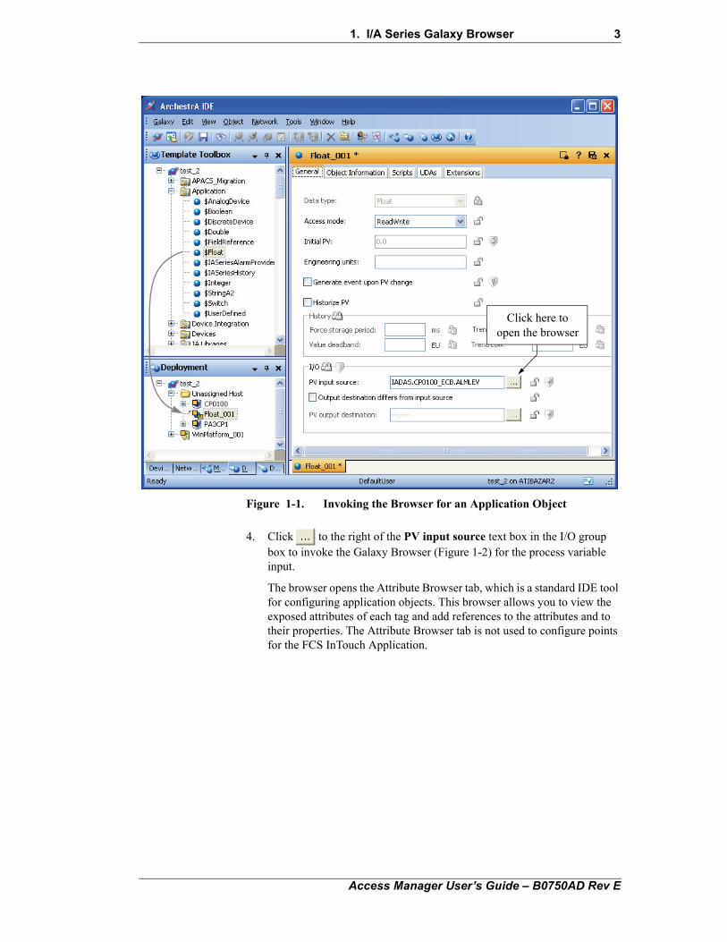
3. Double-click the instance Float_001 in Figure 1-1 to open the object in the editor pane.
The editor opens with the General tab for the float variable.
Access Manager User’s Guide – B0750AD Rev E
1. I/A Series Galaxy Browser 3
Figure 1-1. Invoking the Browser for an Application Object
4. Click to the right of the PV input source text box in the I/O group box to invoke the Galaxy Browser (Figure 1-2) for the process variable input.
The browser opens the Attribute Browser tab, which is a standard IDE tool for configuring application objects. This browser allows you to view the exposed attributes of each tag and add references to the attributes and to their properties. The Attribute Browser tab is not used to configure points for the FCS InTouch Application.
Click here toopen the browser
Access Manager User’s Guide – B0750AD Rev E
4 1. I/A Series Galaxy Browser
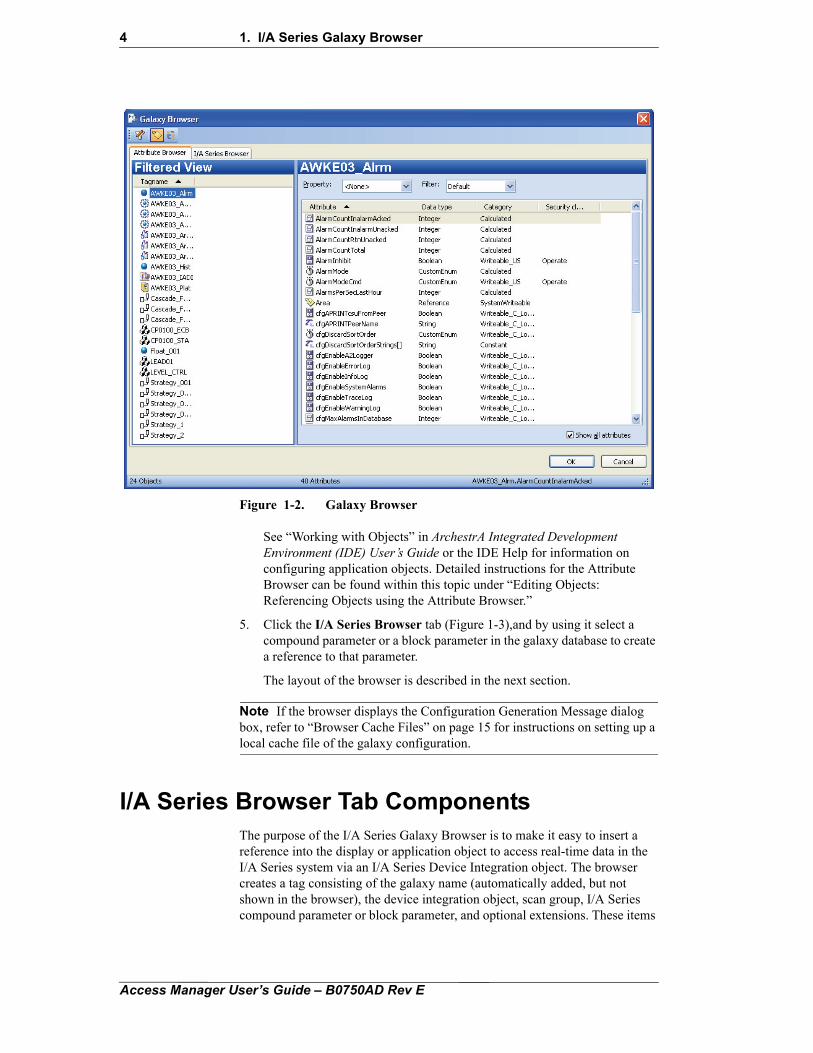
Figure 1-2. Galaxy BrowserSee “Working with Objects” in ArchestrA Integrated Development Environment (IDE) User’s Guide or the IDE Help for information on configuring application objects. Detailed instructions for the Attribute Browser can be found within this topic under “Editing Objects: Referencing Objects using the Attribute Browser.”
5. Click the I/A Series Browser tab (Figure 1-3),and by using it select a compound parameter or a block parameter in the galaxy database to create a reference to that parameter.
The layout of the browser is described in the next section.
Note If the browser displays the Configuration Generation Message dialog box, refer to “Browser Cache Files” on page 15 for instructions on setting up a local cache file of the galaxy configuration.
I/A Series Browser Tab ComponentsThe purpose of the I/A Series Galaxy Browser is to make it easy to insert a reference into the display or application object to access real-time data in the I/A Series system via an I/A Series Device Integration object. The browser creates a tag consisting of the galaxy name (automatically added, but not shown in the browser), the device integration object, scan group, I/A Series compound parameter or block parameter, and optional extensions. These items
Access Manager User’s Guide – B0750AD Rev E
1. I/A Series Galaxy Browser 5
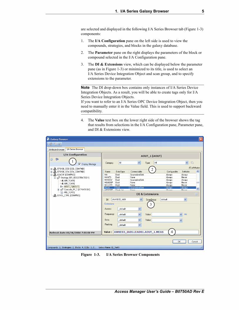
are selected and displayed in the following I/A Series Browser tab (Figure 1-3) components:
1. The I/A Configuration pane on the left side is used to view the compounds, strategies, and blocks in the galaxy database.
2. The Parameter pane on the right displays the parameters of the block or compound selected in the I/A Configuration pane.
3. The DI & Extensions view, which can be displayed below the parameter pane (as in Figure 1-3) or minimized to its title, is used to select an I/A Series Device Integration Object and scan group, and to specify extensions to the parameter.
Note The DI drop-down box contains only instances of I/A Series Device Integration Objects. As a result, you will be able to create tags only for I/A Series Device Integration Objects.If you want to refer to an I/A Series OPC Device Integration Object, then you need to manually enter it in the Value field. This is used to support backward compatibility.
4. The Value text box on the lower right side of the browser shows the tag that results from selections in the I/A Configuration pane, Parameter pane, and DI & Extensions view.
Figure 1-3. I/A Series Browser Components
3
2
1
4
Access Manager User’s Guide – B0750AD Rev E
6 1. I/A Series Galaxy Browser
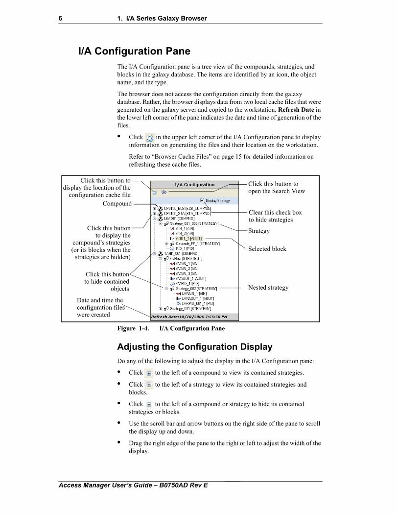
I/A Configuration PaneThe I/A Configuration pane is a tree view of the compounds, strategies, and blocks in the galaxy database. The items are identified by an icon, the object name, and the type.
The browser does not access the configuration directly from the galaxy database. Rather, the browser displays data from two local cache files that were generated on the galaxy server and copied to the workstation. Refresh Date in the lower left corner of the pane indicates the date and time of generation of the files.
• Click in the upper left corner of the I/A Configuration pane to display information on generating the files and their location on the workstation.
Refer to “Browser Cache Files” on page 15 for detailed information on refreshing these cache files.
Figure 1-4. I/A Configuration Pane
Adjusting the Configuration Display
Do any of the following to adjust the display in the I/A Configuration pane:
• Click to the left of a compound to view its contained strategies.
• Click to the left of a strategy to view its contained strategies and blocks.
• Click to the left of a compound or strategy to hide its contained strategies or blocks.
• Use the scroll bar and arrow buttons on the right side of the pane to scroll the display up and down.
• Drag the right edge of the pane to the right or left to adjust the width of the display.
Clear this check boxto hide strategies
Click this buttonto display the
compound’s strategies
Click this button todisplay the location of the
configuration cache file
Click this buttonto hide contained
objects
Strategy
Selected block
Nested strategy
Click this button toopen the Search View
Compound
(or its blocks when thestrategies are hidden)
Date and time the configuration files were created
Access Manager User’s Guide – B0750AD Rev E
1. I/A Series Galaxy Browser 7
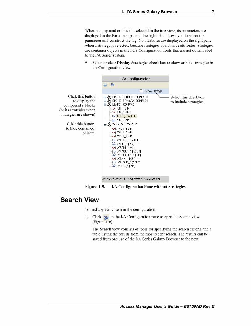
When a compound or block is selected in the tree view, its parameters are displayed in the Parameter pane to the right, that allows you to select the parameter and construct the tag. No attributes are displayed on the right pane when a strategy is selected, because strategies do not have attributes. Strategies are container objects in the FCS Configuration Tools that are not downloaded to the I/A Series system.
• Select or clear Display Strategies check box to show or hide strategies in the Configuration view.
Figure 1-5. I/A Configuration Pane without Strategies
Search ViewTo find a specific item in the configuration:
1. Click in the I/A Configuration pane to open the Search view (Figure 1-6).
The Search view consists of tools for specifying the search criteria and a table listing the results from the most recent search. The results can be saved from one use of the I/A Series Galaxy Browser to the next.
Select this checkboxto include strategies
Click this buttonto display the
compound’s blocks(or its strategies whenstrategies are shown)
Click this buttonto hide contained
objects
Access Manager User’s Guide – B0750AD Rev E
8 1. I/A Series Galaxy Browser
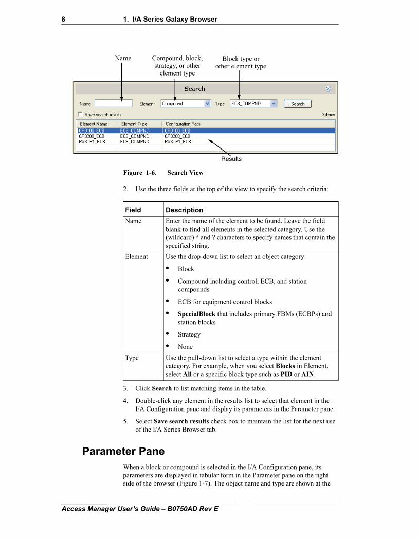
Figure 1-6. Search View
2. Use the three fields at the top of the view to specify the search criteria:
3. Click Search to list matching items in the table.
4. Double-click any element in the results list to select that element in the I/A Configuration pane and display its parameters in the Parameter pane.
5. Select Save search results check box to maintain the list for the next use of the I/A Series Browser tab.
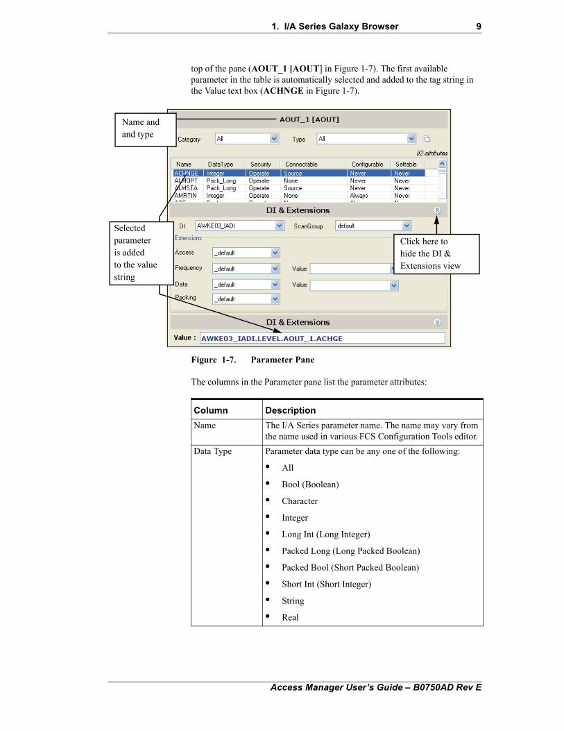
Parameter PaneWhen a block or compound is selected in the I/A Configuration pane, its parameters are displayed in tabular form in the Parameter pane on the right side of the browser (Figure 1-7). The object name and type are shown at the
Name Compound, block,strategy, or other
element type
Results
Block type orother element type
Field Description
Name Enter the name of the element to be found. Leave the field blank to find all elements in the selected category. Use the (wildcard) * and ? characters to specify names that contain the specified string.
Element Use the drop-down list to select an object category:
• Block
• Compound including control, ECB, and station compounds
• ECB for equipment control blocks
• SpecialBlock that includes primary FBMs (ECBPs) and station blocks
• Strategy
• None
Type Use the pull-down list to select a type within the element category. For example, when you select Blocks in Element, select All or a specific block type such as PID or AIN.
Access Manager User’s Guide – B0750AD Rev E
1. I/A Series Galaxy Browser 9
top of the pane (AOUT_1 [AOUT] in Figure 1-7). The first available parameter in the table is automatically selected and added to the tag string in the Value text box (ACHNGE in Figure 1-7).
Figure 1-7. Parameter Pane
The columns in the Parameter pane list the parameter attributes:
Click here tohide the DI &Extensions view
Selectedparameteris addedto the valuestring
Name andand type
Column Description
Name The I/A Series parameter name. The name may vary from the name used in various FCS Configuration Tools editor.
Data Type Parameter data type can be any one of the following:
• All
• Bool (Boolean)
• Character
• Integer
• Long Int (Long Integer)
• Packed Long (Long Packed Boolean)
• Packed Bool (Short Packed Boolean)
• Short Int (Short Integer)
• String
• Real
Access Manager User’s Guide – B0750AD Rev E
10 1. I/A Series Galaxy Browser
Adjusting the Parameter Display
To arrange the parameter and attribute table:
1. Click on the right edge of the DI & Extensions title bar to hide the view and enlarge the Parameter pane.
2. Click any column head to sort parameters on that category; click the column head a second time to reverse the sort order.
3. Drag the right border of a column header to right or left to adjust the width of the column.
Security Access permission required for a user to set the parameter in the run-time system. This permission is configured in the FCS Configuration Tools using ArchestrA security levels. See “I/A Series Security Provider” on page 119 for additional information concerning the access permissions.
Connectable Type of block connection that can be made to the parameter in the FCS Configuration Tools or other configuration editors:
• Source can be read by another parameter
• SourceAndSink can be read from and written to
• DataConnectionSourceAndSink is connection made in the configurator to copy scaling parameters from a source block.
• None
Configurable States whether the parameter can be changed in the FCS Configuration Tools or other configuration editors:
• Once (when the block or compound is created)
• Always
• Never
Settable States whether the parameter can be set by a user with the appropriate security access permission; either Always or Never
Column Description
Access Manager User’s Guide – B0750AD Rev E
1. I/A Series Galaxy Browser 11
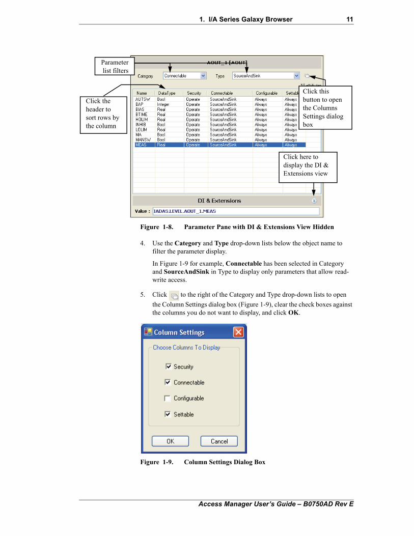
Figure 1-8. Parameter Pane with DI & Extensions View Hidden
4. Use the Category and Type drop-down lists below the object name to filter the parameter display.
In Figure 1-9 for example, Connectable has been selected in Category and SourceAndSink in Type to display only parameters that allow read-write access.
5. Click to the right of the Category and Type drop-down lists to open
the Column Settings dialog box (Figure 1-9), clear the check boxes against the columns you do not want to display, and click OK.
Figure 1-9. Column Settings Dialog Box
Click here todisplay the DI &Extensions view
Click thisbutton to openthe ColumnsSettings dialogbox
Parameterlist filters
Click theheader tosort rows bythe column
Access Manager User’s Guide – B0750AD Rev E
12 1. I/A Series Galaxy Browser
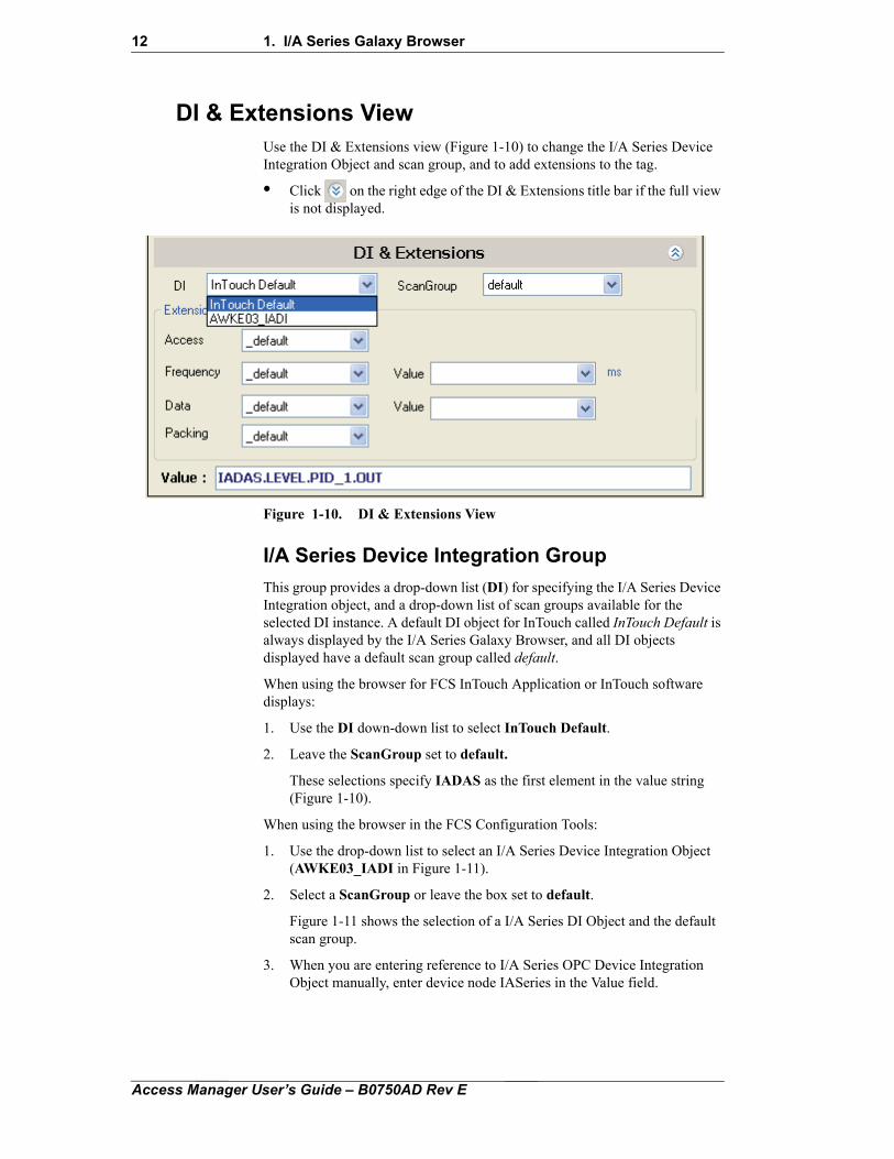
DI & Extensions ViewUse the DI & Extensions view (Figure 1-10) to change the I/A Series Device Integration Object and scan group, and to add extensions to the tag.
• Click on the right edge of the DI & Extensions title bar if the full view is not displayed.
Figure 1-10. DI & Extensions View
I/A Series Device Integration Group
This group provides a drop-down list (DI) for specifying the I/A Series Device Integration object, and a drop-down list of scan groups available for the selected DI instance. A default DI object for InTouch called InTouch Default is always displayed by the I/A Series Galaxy Browser, and all DI objects displayed have a default scan group called default.
When using the browser for FCS InTouch Application or InTouch software displays:
1. Use the DI down-down list to select InTouch Default.
2. Leave the ScanGroup set to default.
These selections specify IADAS as the first element in the value string (Figure 1-10).
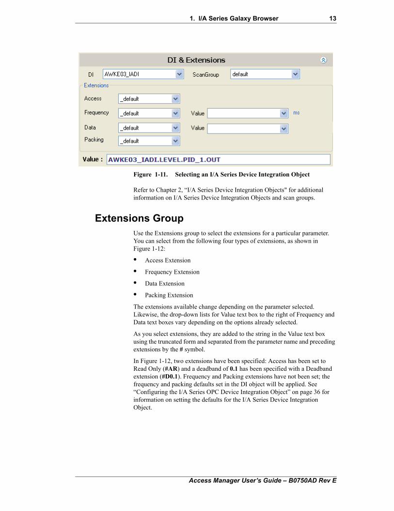
When using the browser in the FCS Configuration Tools:
1. Use the drop-down list to select an I/A Series Device Integration Object (AWKE03_IADI in Figure 1-11).
2. Select a ScanGroup or leave the box set to default.
Figure 1-11 shows the selection of a I/A Series DI Object and the default scan group.
3. When you are entering reference to I/A Series OPC Device Integration Object manually, enter device node IASeries in the Value field.
Access Manager User’s Guide – B0750AD Rev E
1. I/A Series Galaxy Browser 13
Figure 1-11. Selecting an I/A Series Device Integration Object
Refer to Chapter 2, “I/A Series Device Integration Objects" for additional information on I/A Series Device Integration Objects and scan groups.
Extensions GroupUse the Extensions group to select the extensions for a particular parameter. You can select from the following four types of extensions, as shown in Figure 1-12:
• Access Extension
• Frequency Extension
• Data Extension
• Packing Extension
The extensions available change depending on the parameter selected. Likewise, the drop-down lists for Value text box to the right of Frequency and Data text boxes vary depending on the options already selected.
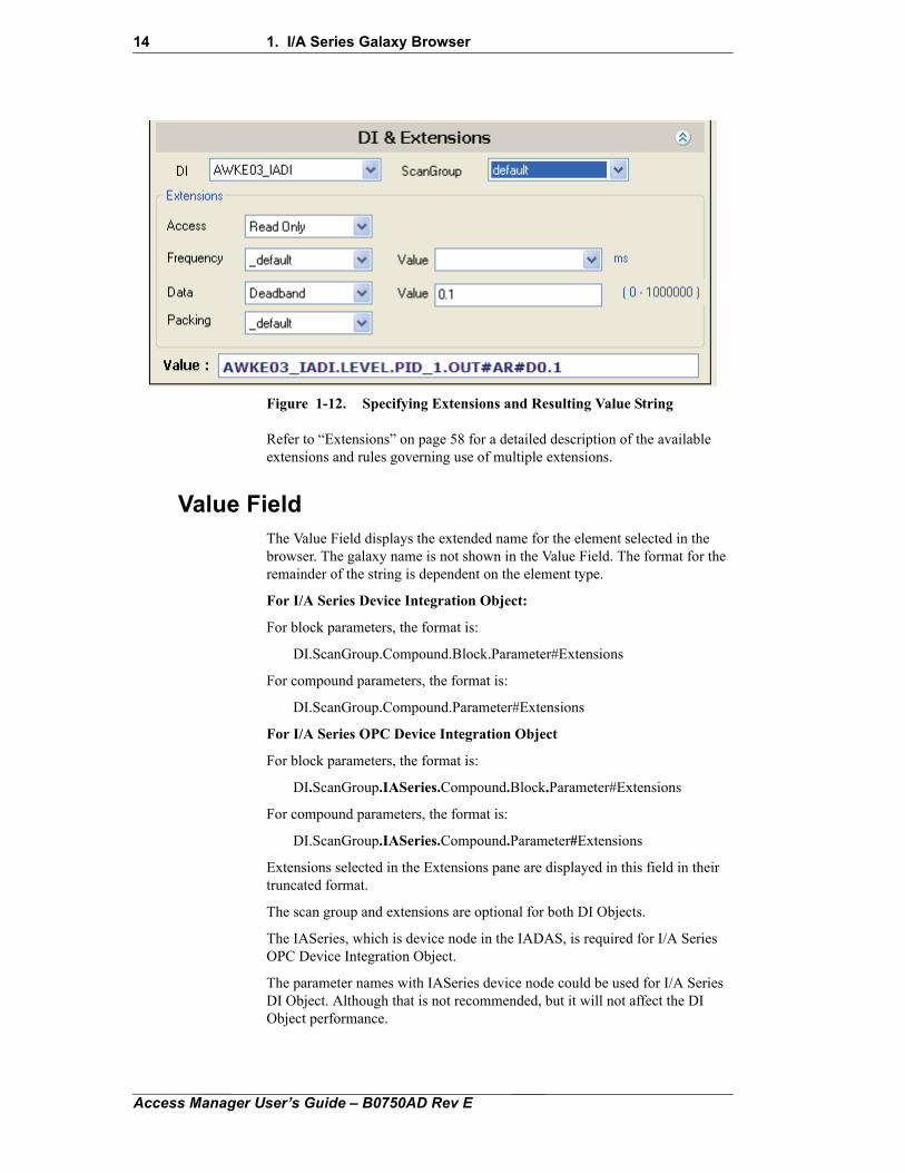
As you select extensions, they are added to the string in the Value text box using the truncated form and separated from the parameter name and preceding extensions by the # symbol.
In Figure 1-12, two extensions have been specified: Access has been set to Read Only (#AR) and a deadband of 0.1 has been specified with a Deadband extension (#D0.1). Frequency and Packing extensions have not been set; the frequency and packing defaults set in the DI object will be applied. See “Configuring the I/A Series OPC Device Integration Object” on page 36 for information on setting the defaults for the I/A Series Device Integration Object.
Access Manager User’s Guide – B0750AD Rev E
14 1. I/A Series Galaxy Browser
Figure 1-12. Specifying Extensions and Resulting Value String
Refer to “Extensions” on page 58 for a detailed description of the available extensions and rules governing use of multiple extensions.
Value FieldThe Value Field displays the extended name for the element selected in the browser. The galaxy name is not shown in the Value Field. The format for the remainder of the string is dependent on the element type.
For I/A Series Device Integration Object:
For block parameters, the format is:
DI.ScanGroup.Compound.Block.Parameter#Extensions
For compound parameters, the format is:
DI.ScanGroup.Compound.Parameter#Extensions
For I/A Series OPC Device Integration Object
For block parameters, the format is:
DI.ScanGroup.IASeries.Compound.Block.Parameter#Extensions
For compound parameters, the format is:
DI.ScanGroup.IASeries.Compound.Parameter#Extensions
Extensions selected in the Extensions pane are displayed in this field in their truncated format.
The scan group and extensions are optional for both DI Objects.
The IASeries, which is device node in the IADAS, is required for I/A Series OPC Device Integration Object.
The parameter names with IASeries device node could be used for I/A Series DI Object. Although that is not recommended, but it will not affect the DI Object performance.
Access Manager User’s Guide – B0750AD Rev E
1. I/A Series Galaxy Browser 15
Browser Cache FilesTo provide for a faster performance, the I/A Series Galaxy Browser (also known as the Tag Browser) uses local cache to access the I/A Series configuration data rather than querying the Galaxy repository on the server every time. The local cache consists of two files, IAConfiguration.xml and DIConfiguration.xml, and the cache needs to be generated on the Galaxy repository server first time, and every time the system configuration is modified. The cache files are generated on the server machine using a separate utility called Cache Generator, and are then copied automatically to each workstation where the I/A Series Browser is used.
Note DIConfiguration.xml file contains information for I/A Series Device Integration Objects. It does not contain information for I/A Series OPC Device Integration Objects.
When the I/A Series Galaxy Browser is opened (that is, when you start the browser and then select the I/A Series Browser tab), the browser searches for the cache files in the following directory:
<ArchestrAFrameworkDir>\FileRepository\IASeriesBrowserCache\<GalaxyName>
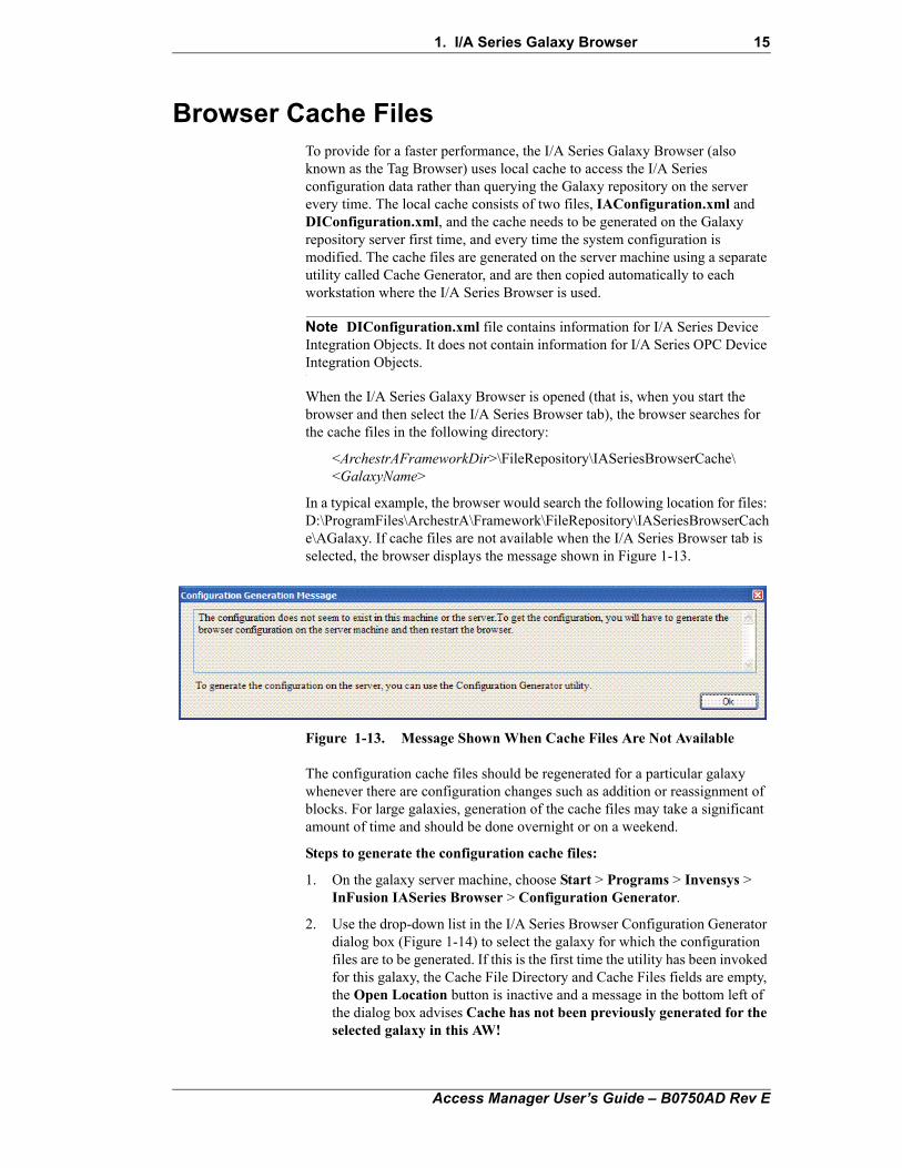
In a typical example, the browser would search the following location for files: D:\ProgramFiles\ArchestrA\Framework\FileRepository\IASeriesBrowserCache\AGalaxy. If cache files are not available when the I/A Series Browser tab is selected, the browser displays the message shown in Figure 1-13.
Figure 1-13. Message Shown When Cache Files Are Not Available
The configuration cache files should be regenerated for a particular galaxy whenever there are configuration changes such as addition or reassignment of blocks. For large galaxies, generation of the cache files may take a significant amount of time and should be done overnight or on a weekend.
Steps to generate the configuration cache files:
1. On the galaxy server machine, choose Start > Programs > Invensys > InFusion IASeries Browser > Configuration Generator.
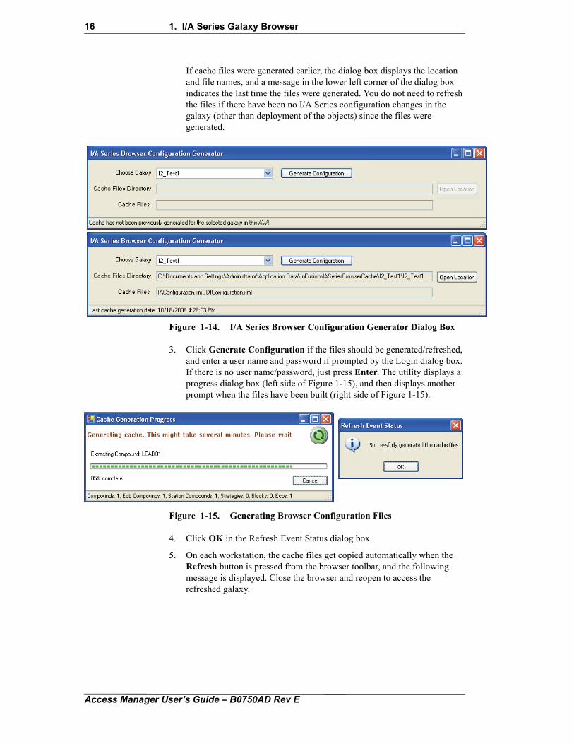
2. Use the drop-down list in the I/A Series Browser Configuration Generator dialog box (Figure 1-14) to select the galaxy for which the configuration files are to be generated. If this is the first time the utility has been invoked for this galaxy, the Cache File Directory and Cache Files fields are empty, the Open Location button is inactive and a message in the bottom left of the dialog box advises Cache has not been previously generated for the selected galaxy in this AW!
Access Manager User’s Guide – B0750AD Rev E
16 1. I/A Series Galaxy Browser
If cache files were generated earlier, the dialog box displays the location and file names, and a message in the lower left corner of the dialog box indicates the last time the files were generated. You do not need to refresh the files if there have been no I/A Series configuration changes in the galaxy (other than deployment of the objects) since the files were generated.
Figure 1-14. I/A Series Browser Configuration Generator Dialog Box
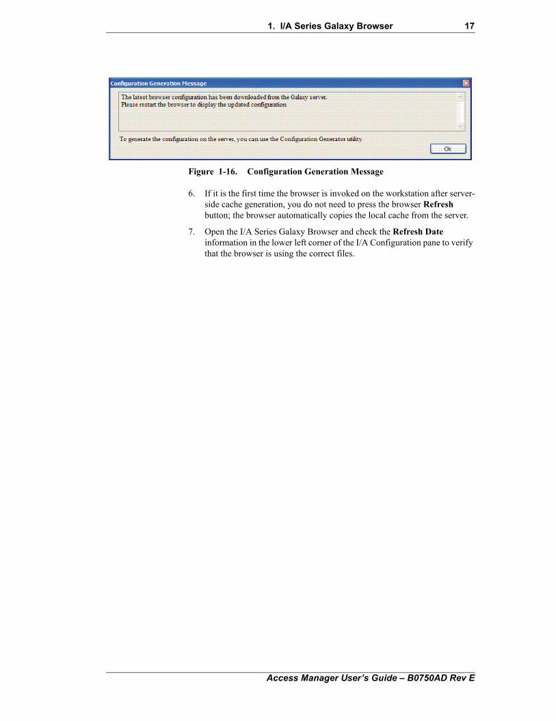
3. Click Generate Configuration if the files should be generated/refreshed, and enter a user name and password if prompted by the Login dialog box. If there is no user name/password, just press Enter. The utility displays a progress dialog box (left side of Figure 1-15), and then displays another prompt when the files have been built (right side of Figure 1-15).
Figure 1-15. Generating Browser Configuration Files
4. Click OK in the Refresh Event Status dialog box.
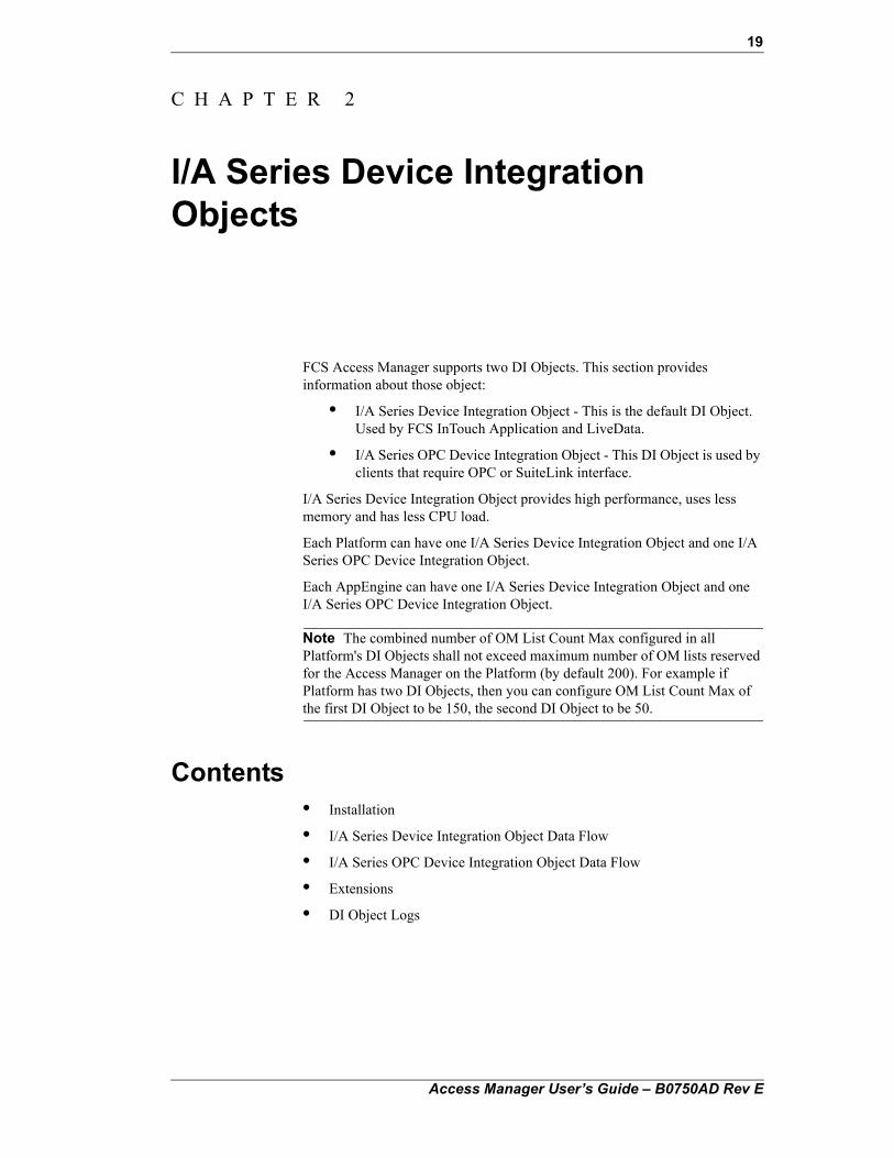
5. On each workstation, the cache files get copied automatically when the Refresh button is pressed from the browser toolbar, and the following message is displayed. Close the browser and reopen to access the refreshed galaxy.
Access Manager User’s Guide – B0750AD Rev E
1. I/A Series Galaxy Browser 17
Figure 1-16. Configuration Generation Message
6. If it is the first time the browser is invoked on the workstation after server-side cache generation, you do not need to press the browser Refresh button; the browser automatically copies the local cache from the server.
7. Open the I/A Series Galaxy Browser and check the Refresh Date information in the lower left corner of the I/A Configuration pane to verify that the browser is using the correct files.
Access Manager User’s Guide – B0750AD Rev E

18 1. I/A Series Galaxy Browser
Access Manager User’s Guide – B0750AD Rev E
19
C H A P T E R 2
I/A Series Device Integration Objects
FCS Access Manager supports two DI Objects. This section provides information about those object:
• I/A Series Device Integration Object - This is the default DI Object. Used by FCS InTouch Application and LiveData.
• I/A Series OPC Device Integration Object - This DI Object is used by clients that require OPC or SuiteLink interface.
I/A Series Device Integration Object provides high performance, uses less memory and has less CPU load.
Each Platform can have one I/A Series Device Integration Object and one I/A Series OPC Device Integration Object.
Each AppEngine can have one I/A Series Device Integration Object and one I/A Series OPC Device Integration Object.
Note The combined number of OM List Count Max configured in all Platform's DI Objects shall not exceed maximum number of OM lists reserved for the Access Manager on the Platform (by default 200). For example if Platform has two DI Objects, then you can configure OM List Count Max of the first DI Object to be 150, the second DI Object to be 50.
Contents• Installation
• I/A Series Device Integration Object Data Flow
• I/A Series OPC Device Integration Object Data Flow
• Extensions
• DI Object Logs
Access Manager User’s Guide – B0750AD Rev E
20 2. I/A Series Device Integration Objects
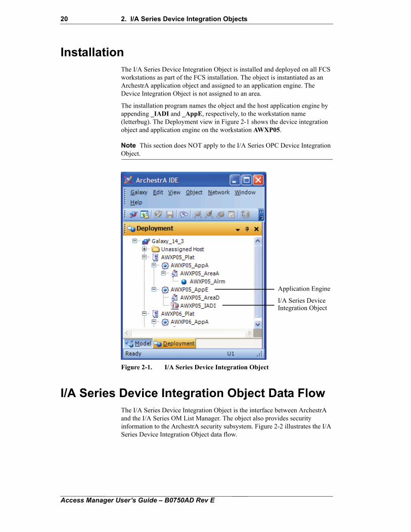
InstallationThe I/A Series Device Integration Object is installed and deployed on all FCS workstations as part of the FCS installation. The object is instantiated as an ArchestrA application object and assigned to an application engine. The Device Integration Object is not assigned to an area.
The installation program names the object and the host application engine by appending _IADI and _AppE, respectively, to the workstation name (letterbug). The Deployment view in Figure 2-1 shows the device integration object and application engine on the workstation AWXP05.
Note This section does NOT apply to the I/A Series OPC Device Integration Object.
Figure 2-1. I/A Series Device Integration Object
I/A Series Device Integration Object Data FlowThe I/A Series Device Integration Object is the interface between ArchestrA and the I/A Series OM List Manager. The object also provides security information to the ArchestrA security subsystem. Figure 2-2 illustrates the I/A Series Device Integration Object data flow.
Application Engine
I/A Series DeviceIntegration Object
Access Manager User’s Guide – B0750AD Rev E
2. I/A Series Device Integration Objects 21
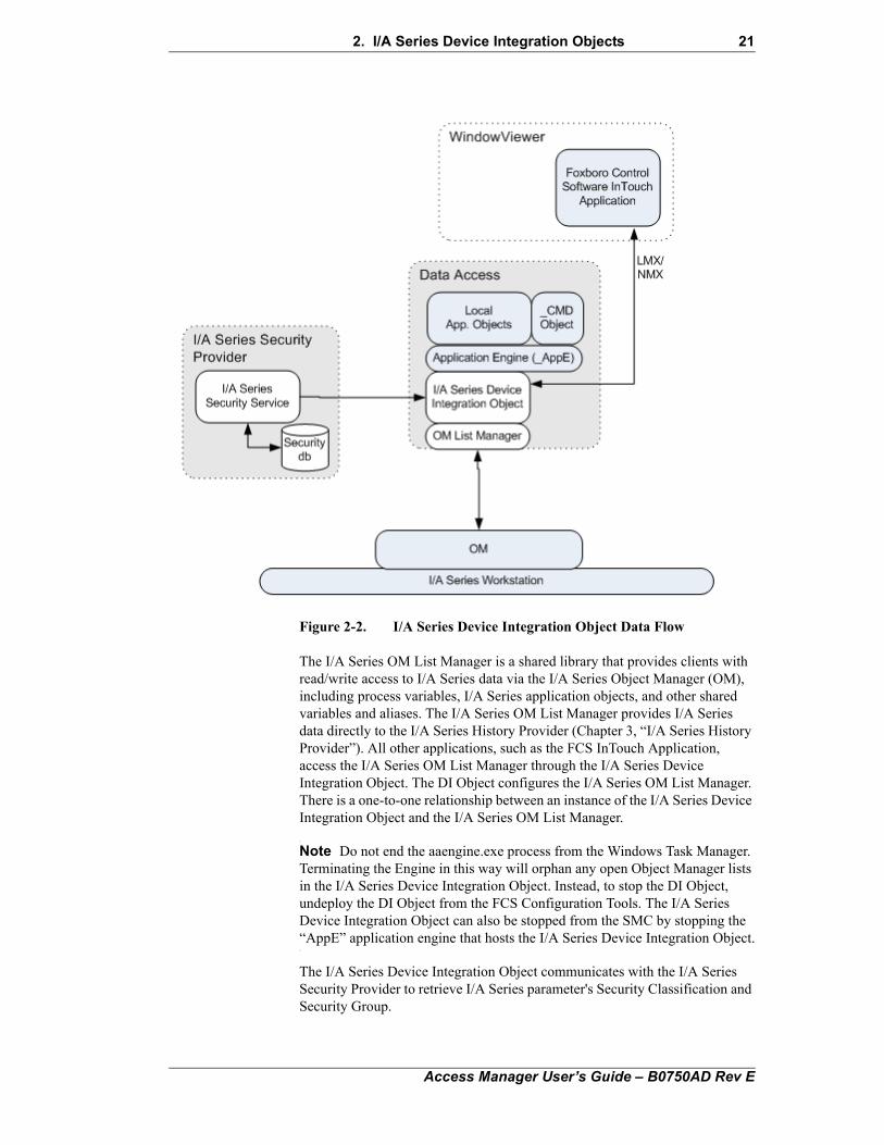
Figure 2-2. I/A Series Device Integration Object Data Flow
The I/A Series OM List Manager is a shared library that provides clients with read/write access to I/A Series data via the I/A Series Object Manager (OM), including process variables, I/A Series application objects, and other shared variables and aliases. The I/A Series OM List Manager provides I/A Series data directly to the I/A Series History Provider (Chapter 3, “I/A Series History Provider”). All other applications, such as the FCS InTouch Application, access the I/A Series OM List Manager through the I/A Series Device Integration Object. The DI Object configures the I/A Series OM List Manager. There is a one-to-one relationship between an instance of the I/A Series Device Integration Object and the I/A Series OM List Manager.
Note Do not end the aaengine.exe process from the Windows Task Manager. Terminating the Engine in this way will orphan any open Object Manager lists in the I/A Series Device Integration Object. Instead, to stop the DI Object, undeploy the DI Object from the FCS Configuration Tools. The I/A Series Device Integration Object can also be stopped from the SMC by stopping the “AppE” application engine that hosts the I/A Series Device Integration Object.
The I/A Series Device Integration Object communicates with the I/A Series Security Provider to retrieve I/A Series parameter's Security Classification and Security Group.
Access Manager User’s Guide – B0750AD Rev E
22 2. I/A Series Device Integration Objects
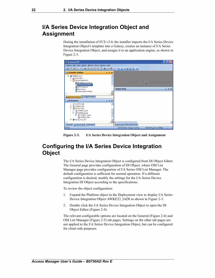
I/A Series Device Integration Object and Assignment
During the installation of FCS v3.0, the installer imports the I/A Series Device Integration Object's template into a Galaxy, creates an instance of I/A Series Device Integration Object, and assigns it to an application engine, as shown in Figure 2-3.
Figure 2-3. I/A Series Device Integration Object and Assignment
Configuring the I/A Series Device Integration Object
The I/A Series Device Integration Object is configured from DI Object Editor. The General page provides configuration of DI Object, where OM List Manager page provides configuration of I/A Series OM List Manager. The default configuration is sufficient for normal operation. If a different configuration is desired, modify the settings for the I/A Series Device Integration DI Object according to the specifications.
To review the object configuration:
1. Expand the Platform object in the Deployment view to display I/A Series Device Integration Object AWKE23_IADI as shown in Figure 2-3.
2. Double click the I/A Series Device Integration Object to open the DI Object Editor (Figure 2-4).
The relevant configurable options are located on the General (Figure 2-4) and OM List Manager (Figure 2-5) tab pages. Settings on the other tab pages are not applied to the I/A Series Device Integration Object, but can be configured for client-side purposes.
Access Manager User’s Guide – B0750AD Rev E
2. I/A Series Device Integration Objects 23
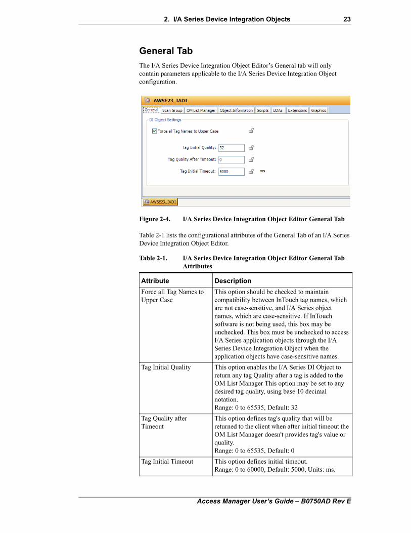
General Tab
The I/A Series Device Integration Object Editor’s General tab will only contain parameters applicable to the I/A Series Device Integration Object configuration.
Figure 2-4. I/A Series Device Integration Object Editor General Tab
Table 2-1 lists the configurational attributes of the General Tab of an I/A Series Device Integration Object Editor.
Table 2-1. I/A Series Device Integration Object Editor General Tab Attributes
Attribute Description
Force all Tag Names to Upper Case
This option should be checked to maintain compatibility between InTouch tag names, which are not case-sensitive, and I/A Series object names, which are case-sensitive. If InTouch software is not being used, this box may be unchecked. This box must be unchecked to access I/A Series application objects through the I/A Series Device Integration Object when the application objects have case-sensitive names.
Tag Initial Quality This option enables the I/A Series DI Object to return any tag Quality after a tag is added to the OM List Manager This option may be set to any desired tag quality, using base 10 decimal notation. Range: 0 to 65535, Default: 32
Tag Quality after Timeout
This option defines tag's quality that will be returned to the client when after initial timeout the OM List Manager doesn't provides tag's value or quality.Range: 0 to 65535, Default: 0
Tag Initial Timeout This option defines initial timeout. Range: 0 to 60000, Default: 5000, Units: ms.
Access Manager User’s Guide – B0750AD Rev E
24 2. I/A Series Device Integration Objects
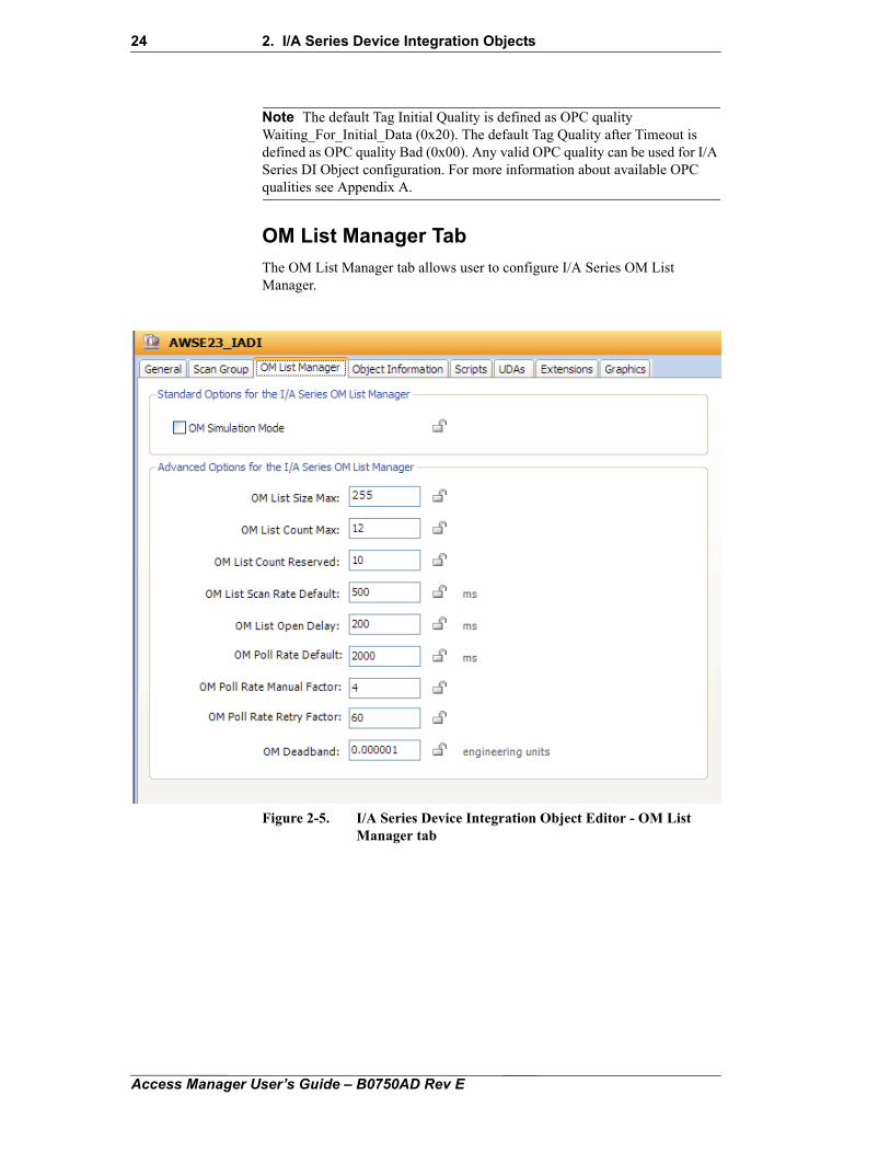
Note The default Tag Initial Quality is defined as OPC quality Waiting_For_Initial_Data (0x20). The default Tag Quality after Timeout is defined as OPC quality Bad (0x00). Any valid OPC quality can be used for I/A Series DI Object configuration. For more information about available OPC qualities see Appendix A.
OM List Manager Tab
The OM List Manager tab allows user to configure I/A Series OM List Manager.
Figure 2-5. I/A Series Device Integration Object Editor - OM List Manager tab
Access Manager User’s Guide – B0750AD Rev E
2. I/A Series Device Integration Objects 25
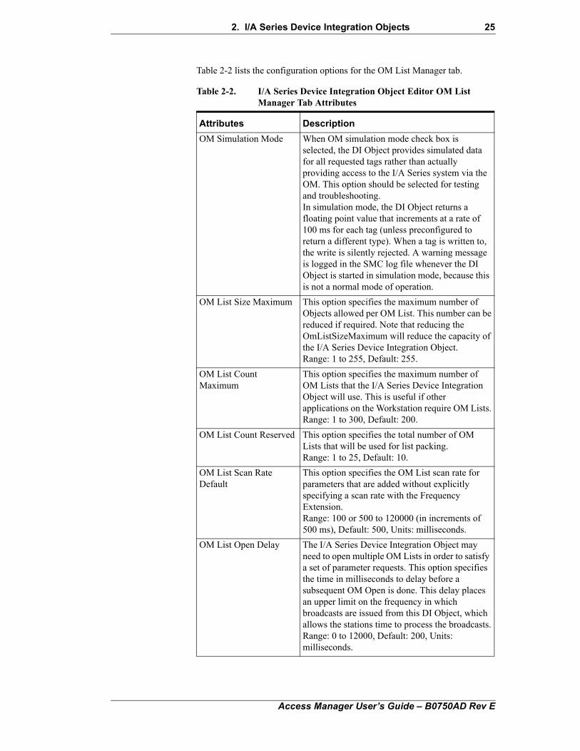
Table 2-2 lists the configuration options for the OM List Manager tab.
Table 2-2. I/A Series Device Integration Object Editor OM List Manager Tab Attributes
Attributes Description
OM Simulation Mode When OM simulation mode check box is selected, the DI Object provides simulated data for all requested tags rather than actually providing access to the I/A Series system via the OM. This option should be selected for testing and troubleshooting.In simulation mode, the DI Object returns a floating point value that increments at a rate of 100 ms for each tag (unless preconfigured to return a different type). When a tag is written to, the write is silently rejected. A warning message is logged in the SMC log file whenever the DI Object is started in simulation mode, because this is not a normal mode of operation.
OM List Size Maximum This option specifies the maximum number ofObjects allowed per OM List. This number can bereduced if required. Note that reducing theOmListSizeMaximum will reduce the capacity ofthe I/A Series Device Integration Object.Range: 1 to 255, Default: 255.
OM List CountMaximum
This option specifies the maximum number of OM Lists that the I/A Series Device Integration Object will use. This is useful if other applications on the Workstation require OM Lists.Range: 1 to 300, Default: 200.
OM List Count Reserved This option specifies the total number of OMLists that will be used for list packing.Range: 1 to 25, Default: 10.
OM List Scan RateDefault
This option specifies the OM List scan rate for parameters that are added without explicitly specifying a scan rate with the Frequency Extension.Range: 100 or 500 to 120000 (in increments of500 ms), Default: 500, Units: milliseconds.
OM List Open Delay The I/A Series Device Integration Object may need to open multiple OM Lists in order to satisfy a set of parameter requests. This option specifies the time in milliseconds to delay before a subsequent OM Open is done. This delay places an upper limit on the frequency in which broadcasts are issued from this DI Object, which allows the stations time to process the broadcasts.Range: 0 to 12000, Default: 200, Units:milliseconds.
Access Manager User’s Guide – B0750AD Rev E
26 2. I/A Series Device Integration Objects
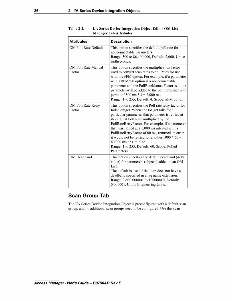
Scan Group Tab
The I/A Series Device Integration Object is preconfigured with a default scan group, and no additional scan groups need to be configured. Use the Scan
OM Poll Rate Default This option specifies the default poll rate for nonconnectable parameters.Range: 500 to 86,400,000, Default: 2,000, Units:milliseconds.
OM Poll Rate ManualFactor
This option specifies the multiplication factorused to convert scan rates to poll rates for usewith the #FM option. For example, if a parameterwith a #FM500 option is a nonconnectableparameter and the PollRateManualFactor is 4, theparameter will be added to the poll publisher withperiod of 500 ms * 4 = 2,000 ms.Range: 1 to 255, Default: 4, Scope: #FM option
OM Poll Rate Retry Factor
This option specifies the Poll rate retry factor forfailed omget. When an OM get fails for aparticular parameter, that parameter is retried atits original Poll Rate multiplied by thePollRateRetryFactor. For example, if a parameterthat was Polled at a 1,000 ms interval with aPollRateRetryFactor of 60 ms, returned an error,it would not be retried for another 1000 * 60 =60,000 ms or 1 minute.Range: 1 to 255, Default: 60, Scope: PolledParameters
OM Deadband This option specifies the default deadband (deltavalue) for parameters (objects) added to an OM List.The default is used if the Item does not have adeadband specified in a tag name extension.Range: 0 or 0.000001 to 1000000.0, Default:0.000001, Units: Engineering Units.
Table 2-2. I/A Series Device Integration Object Editor OM List Manager Tab Attributes
Attributes Description
Access Manager User’s Guide – B0750AD Rev E
2. I/A Series Device Integration Objects 27
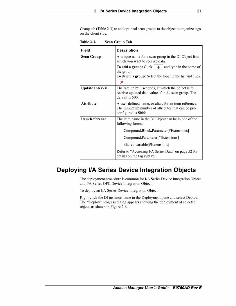
Group tab (Table 2-3) to add optional scan groups to the object to organize tags on the client side.
Deploying I/A Series Device Integration ObjectsThe deployment procedure is common for I/A Series Device Integration Object and I/A Series OPC Device Integration Object.
To deploy an I/A Series Device Integration Object:
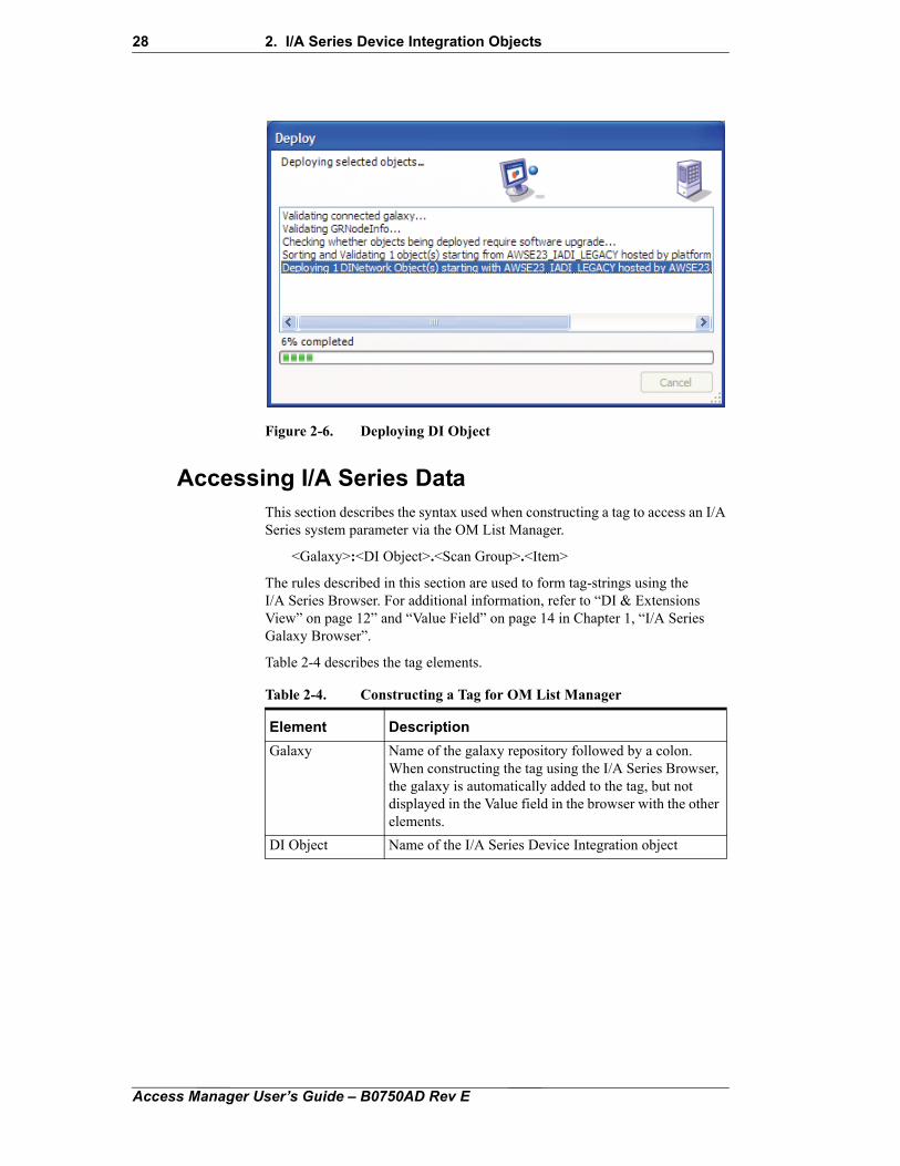
Right-click the DI instance name in the Deployment pane and select Deploy. The “Deploy” progress dialog appears showing the deployment of selected object, as shown in Figure 2-6.
Table 2-3. Scan Group Tab
Field Description
Scan Group A unique name for a scan group in the DI Object from which you want to receive data.
To add a group: Click and type in the name of the group.To delete a group: Select the topic in the list and click
.
Update Interval The rate, in milliseconds, at which the object is to receive updated data values for the scan group. The default is 500.
Attribute A user-defined name, or alias, for an item reference. The maximum number of attributes that can be pre-configured is 5000.
Item Reference The item name in the DI Object can be in one of the following forms:
Compound.Block.Parameter[#Extensions]
Compound.Parameter[#Extensions]
Shared variable[#Extensions]
Refer to “Accessing I/A Series Data” on page 52 for details on the tag syntax.
Access Manager User’s Guide – B0750AD Rev E
28 2. I/A Series Device Integration Objects
Figure 2-6. Deploying DI Object
Accessing I/A Series DataThis section describes the syntax used when constructing a tag to access an I/A Series system parameter via the OM List Manager.
<Galaxy>:<DI Object>.<Scan Group>.<Item>
The rules described in this section are used to form tag-strings using the I/A Series Browser. For additional information, refer to “DI & Extensions View” on page 12” and “Value Field” on page 14 in Chapter 1, “I/A Series Galaxy Browser”.
Table 2-4 describes the tag elements.
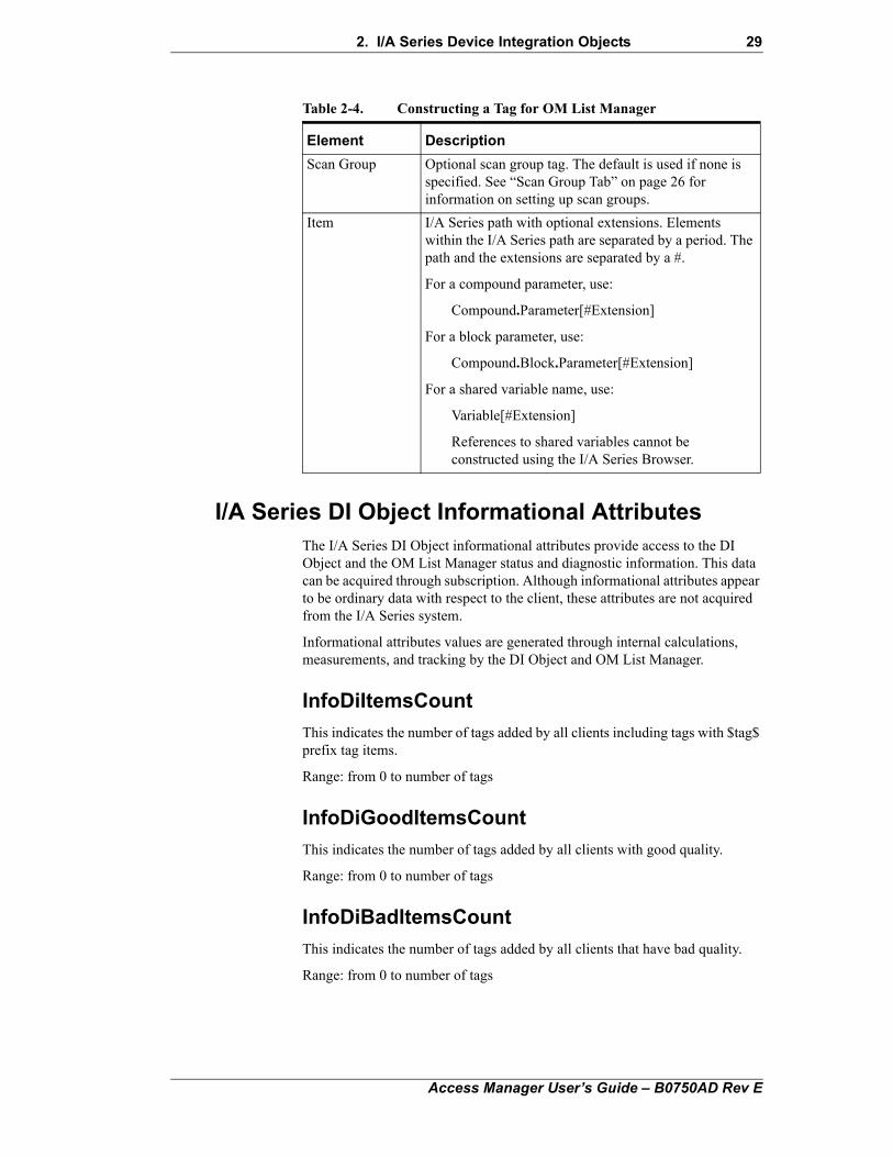
Table 2-4. Constructing a Tag for OM List Manager
Element Description
Galaxy Name of the galaxy repository followed by a colon. When constructing the tag using the I/A Series Browser, the galaxy is automatically added to the tag, but not displayed in the Value field in the browser with the other elements.
DI Object Name of the I/A Series Device Integration object
Access Manager User’s Guide – B0750AD Rev E
2. I/A Series Device Integration Objects 29
I/A Series DI Object Informational Attributes The I/A Series DI Object informational attributes provide access to the DI Object and the OM List Manager status and diagnostic information. This data can be acquired through subscription. Although informational attributes appear to be ordinary data with respect to the client, these attributes are not acquired from the I/A Series system.
Informational attributes values are generated through internal calculations, measurements, and tracking by the DI Object and OM List Manager.
InfoDiItemsCount
This indicates the number of tags added by all clients including tags with $tag$ prefix tag items.
Range: from 0 to number of tags
InfoDiGoodItemsCount
This indicates the number of tags added by all clients with good quality.
Range: from 0 to number of tags
InfoDiBadItemsCount
This indicates the number of tags added by all clients that have bad quality.
Range: from 0 to number of tags
Scan Group Optional scan group tag. The default is used if none is specified. See “Scan Group Tab” on page 26 for information on setting up scan groups.
Item I/A Series path with optional extensions. Elements within the I/A Series path are separated by a period. The path and the extensions are separated by a #.
For a compound parameter, use:
Compound.Parameter[#Extension]
For a block parameter, use:
Compound.Block.Parameter[#Extension]
For a shared variable name, use:
Variable[#Extension]
References to shared variables cannot be constructed using the I/A Series Browser.
Table 2-4. Constructing a Tag for OM List Manager
Element Description
Access Manager User’s Guide – B0750AD Rev E
30 2. I/A Series Device Integration Objects
InfoDiWaitingItemsCount
This indicates the number of tags added by all clients that are waiting for initial respond.
Range: from 0 to number of tags
InfoDiNotFoundItemsCount
This indicates the number of tags added by all clients that were not found (no response from OM).
Range: from 0 to number of tags
InfoDiUncertainItemsCount
This indicates the number of tags that have the Uncertain quality.
Range: from 0 to number of tags
InfoDiTagItemsCount
This indicates the number of tags with $tag$ prefix added by all clients.
Range: from 0 to number of tags
InfoOmListCountAvailable
This is the number of OM Lists that are available for use by the DI Object and subsequently the client. This number is OmListCountMaximum minus the number of reserved lists (OmListCountReserved) and the current number of OM Lists opened by the DI Object.
Range: 0 to OmListCountMaximum
InfoOmListsUsed
This indicates the number of used OM lists by all clients.
Range: from 0 to maximum lists limit.
InfoOmListsFree
This indicates the number of used OM lists available for use (not containing any tags).
Range: from 0 to maximum lists limit.
InfoOmPollItemsCount
This indicates the number of tags added by all clients that OM List Manager is currently polling for.
Range: from 0 to number of tags
Access Manager User’s Guide – B0750AD Rev E
2. I/A Series Device Integration Objects 31
InfoOmRetryItemsCount
This indicates the number of tags added by all clients that OM List Manager is currently retrying.
Range: from 0 to number of tags
InfoOmScanItemsCount
This indicates the number of tags added by all clients that OM List Manager maintains in the OM lists.
Range: from 0 to number of tags
InfoOmPollOverrunItemsCount
This indicates the number of tags that were polled with slower rate that is configured.
Range: from 0 to number of tags
InfoOmListCountClientLimit
This is the total number of OM Lists that may be used by the client, which is OmListCountReserved less than OmListCountMaximum, to allow for list packing. This value is static since it is determined through configuration.
Range: N/A
Tags with $tag$ PrefixThe tags with $tag$ prefix provide clients with the ability to obtain the I/A Series parameter name and extension as a string without performing any additional parsing operations. This data can be acquired through a transaction or subscription mechanism.
Note Because subscriptions provide data on a change-driven basis and the string value returned will never change, the usefulness of the subscription mechanism is minimal.
Although tags appear to be ordinary data with respect to the client, the values are not acquired from the I/A Series system. Tag values are generated from the tag name itself. The syntax is as follows (two forms are supported):
Galaxy:IADI.$tag$COMP.BLOCK.PARAM#Extensions
or
Galaxy:IADI.$tag$.COMP.BLOCK.PARAM#Extensions
Either of the above tags will return the following:
COMP.BLOCK.PARAM#Extensions
Access Manager User’s Guide – B0750AD Rev E
32 2. I/A Series Device Integration Objects
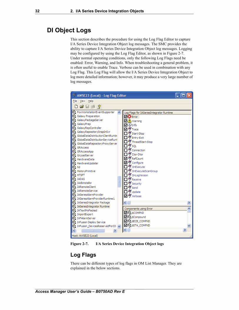
DI Object LogsThis section describes the procedure for using the Log Flag Editor to capture I/A Series Device Integration Object log messages. The SMC provides the ability to capture I/A Series Device Integration Object log messages. Logging may be configured by using the Log Flag Editor, as shown in Figure 2-7. Under normal operating conditions, only the following Log Flags need be enabled: Error, Warning, and Info. When troubleshooting a general problem, it is often useful to enable Trace. Verbose can be used in combination with any Log Flag. This Log Flag will allow the I/A Series Device Integration Object to log more detailed information; however, it may produce a very large number of log messages.
Figure 2-7. I/A Series Device Integration Object logs
Log Flags
There can be different types of log flags in OM List Manager. They are explained in the below sections.
Access Manager User’s Guide – B0750AD Rev E
2. I/A Series Device Integration Objects 33
Configure
The Configure log flag is used to log OM List Manager configuration changes. With the verbose flag, adding and removing tags is logged.
Receive
The Receive log flag is used to log actions resulting in data being read or received from I/A Series parameters or shared variables. With the Verbose flag, the results of conversions to other data types, such as .NET or ArchestrA, from I/A Series data types are logged. This includes value, quality and timestamp conversions.
Send
The Send log flag is used to log actions resulting in data being sent or written to I/A Series parameters or shared variables. With the Verbose flag, the results of conversions from other data types, such as .NET or ArchestrA, to I/A Series data types are logged. This includes value, quality and timestamp conversions.
Update
The Update log flag is used to log parameter updates to timestamp, value and/or status as they are received from the OM via the OM List Managers scan or poll mechanism.
Note Above mentioned log flags will allow the OM List Manager to log more detailed information; however it may produce a very large number of log messages. These are basically for troubleshooting the problems.
Note The messages generated by the OM List Manager will be published under IASeriesIntegrator Runtime component.
All error, warning, and informational messages generated within the I/A Series Device Integration Object will be logged.
Security
The Security log flag is used to log information related to retrieving parameter's classification and Security Group information from the I/A Series Security Provider.
Error Code MappingError codes will be mapped between the ArchestrA MX and I/A Series. All warning and errors returned to I/A Series Device Integration Object from OM List Manager will be logged in the ArchestrA logger as warning or errors.
Access Manager User’s Guide – B0750AD Rev E
34 2. I/A Series Device Integration Objects
I/A Series OPC Device Integration Object Data Flow
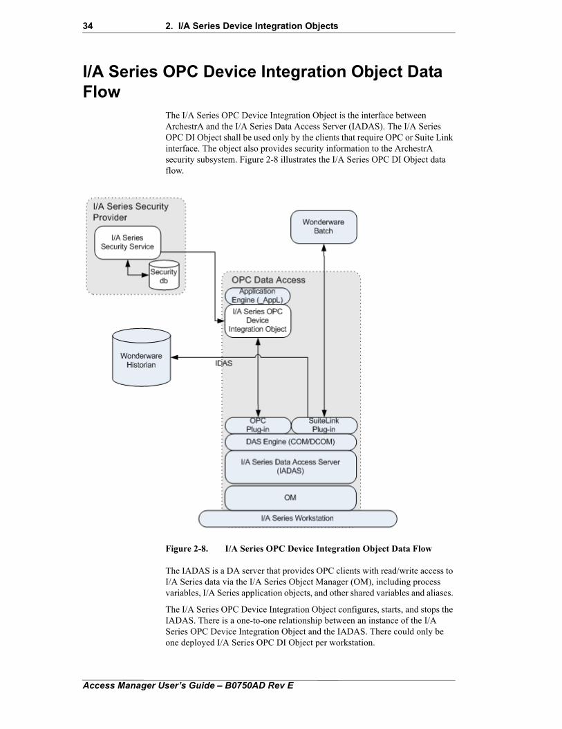
The I/A Series OPC Device Integration Object is the interface between ArchestrA and the I/A Series Data Access Server (IADAS). The I/A Series OPC DI Object shall be used only by the clients that require OPC or Suite Link interface. The object also provides security information to the ArchestrA security subsystem. Figure 2-8 illustrates the I/A Series OPC DI Object data flow.
Figure 2-8. I/A Series OPC Device Integration Object Data Flow
The IADAS is a DA server that provides OPC clients with read/write access to I/A Series data via the I/A Series Object Manager (OM), including process variables, I/A Series application objects, and other shared variables and aliases.
The I/A Series OPC Device Integration Object configures, starts, and stops the IADAS. There is a one-to-one relationship between an instance of the I/A Series OPC Device Integration Object and the IADAS. There could only be one deployed I/A Series OPC DI Object per workstation.
Access Manager User’s Guide – B0750AD Rev E
2. I/A Series Device Integration Objects 35
Note Do not end the IADAS.exe process from the Windows Task Manager or make Foxboro.IASeries.DAServer.1 unavailable from the SMC DAServer Manager. Terminating the IADAS in this way will orphan any open Object Manager lists. Instead, to stop the IADAS service, undeploy the I/A Series OPC DI Object from the FCS Configuration Tools. The IADAS service can also be stopped from the SMC by stopping the "AppE" application engine that hosts the I/A Series OPC DI Object.
The I/A Series OPC DI Object supports the following operations in the I/O points of the IADAS:
• Subscriptions, which are implemented via scan groups, as described on page 53
• Read transactions, which are implemented via block reads, as described on page 53
• Write transactions, which are implemented via block writes, as described on page 53
The I/A Series OPC Device Integration Object communicates with the I/A Series Security Provider, which supplies tag Security Classification and Security Group information to ArchestrA security. The I/A Series Security Provider is described in Chapter 6, “I/A Series Security Provider”.
I/A Series OPC Device Integration Object Import and Assignment
The I/A Series OPC Device Integration Object is manually imported into a Galaxy and assigned to an Application Engine, as shown in Figure 2-10.
To import a DI Object:
1. In the ArchestrA IDE screen, click Galaxy > Import > Objects. Specify the location of the file D:\Program Files\ArchestrA\Framework\Bin\Invensys\InFusionIntegrator. A progress dialog box Figure 2-9 appears showing the import process of the objects from the InFusionIntegrator.aaPKG file:
Access Manager User’s Guide – B0750AD Rev E
36 2. I/A Series Device Integration Objects
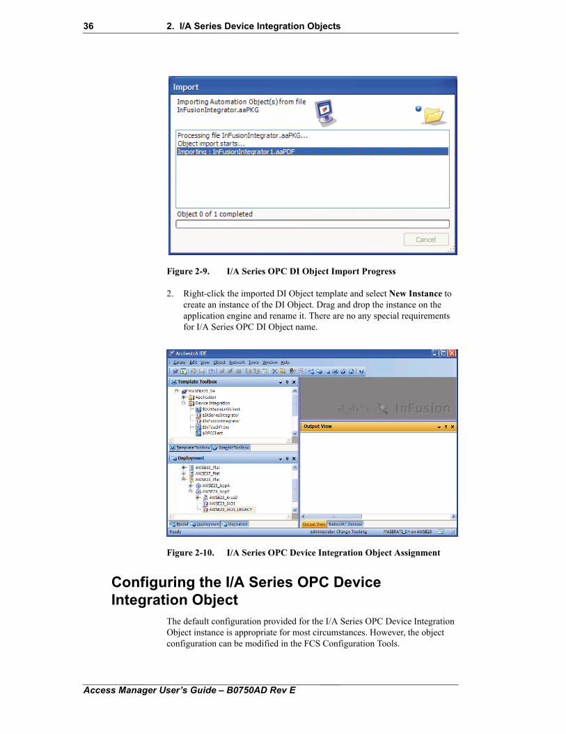
Figure 2-9. I/A Series OPC DI Object Import Progress
2. Right-click the imported DI Object template and select New Instance to create an instance of the DI Object. Drag and drop the instance on the application engine and rename it. There are no any special requirements for I/A Series OPC DI Object name.
Figure 2-10. I/A Series OPC Device Integration Object Assignment
Configuring the I/A Series OPC Device Integration Object
The default configuration provided for the I/A Series OPC Device Integration Object instance is appropriate for most circumstances. However, the object configuration can be modified in the FCS Configuration Tools.
Access Manager User’s Guide – B0750AD Rev E
2. I/A Series Device Integration Objects 37
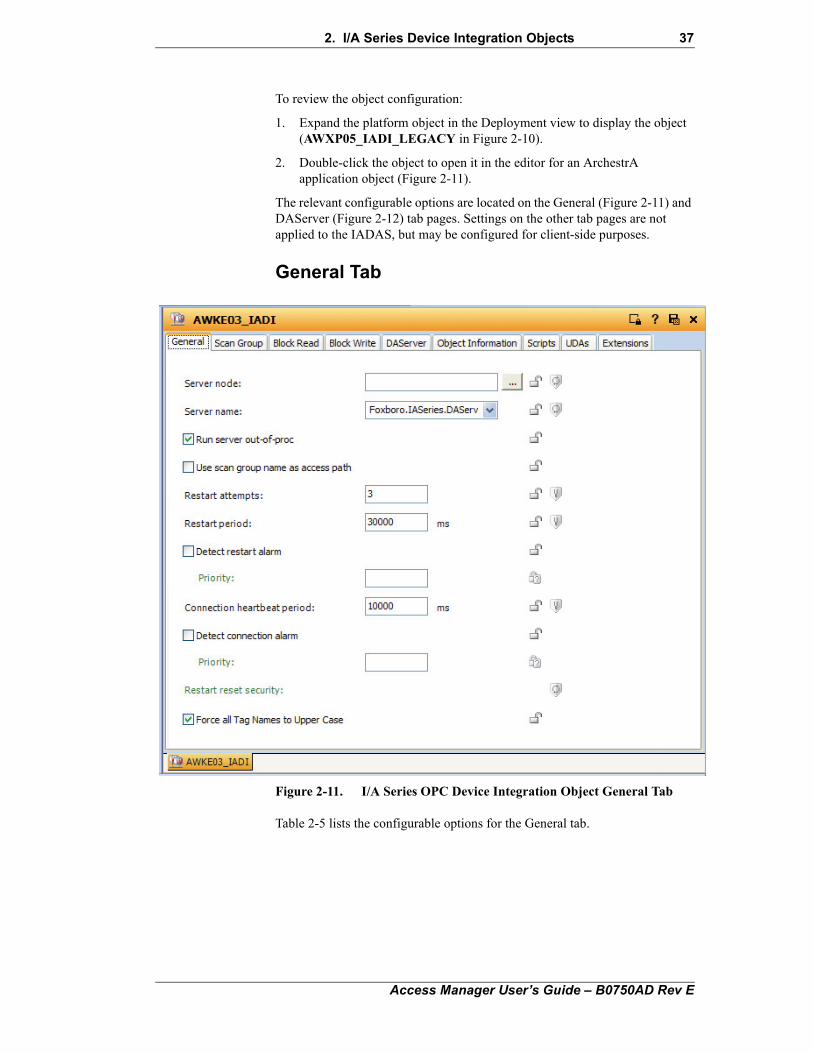
To review the object configuration:
1. Expand the platform object in the Deployment view to display the object (AWXP05_IADI_LEGACY in Figure 2-10).
2. Double-click the object to open it in the editor for an ArchestrA application object (Figure 2-11).
The relevant configurable options are located on the General (Figure 2-11) and DAServer (Figure 2-12) tab pages. Settings on the other tab pages are not applied to the IADAS, but may be configured for client-side purposes.
General Tab
Figure 2-11. I/A Series OPC Device Integration Object General Tab
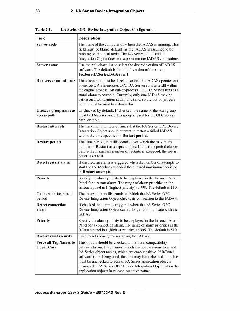
Table 2-5 lists the configurable options for the General tab.
Access Manager User’s Guide – B0750AD Rev E
38 2. I/A Series Device Integration Objects
Table 2-5. I/A Series OPC Device Integration Object Configuration
Field Description
Server node The name of the computer on which the IADAS is running. This field must be blank (default) as the IADAS is assumed to be running on the local node. The I/A Series OPC Device Integration Object does not support remote IADAS connections.
Server name Use the pull-down list to select the desired version of IADAS software. The default is the initial version of the server, Foxboro.IASeries.DAServer.1.
Run server out-of-proc This checkbox must be checked so that the IADAS operates out-of-process. An in-process OPC DA Server runs as a .dll within the engine process. An out-of-process OPC DA Server runs as a stand-alone executable. Currently, only one IADAS may be active on a workstation at any one time, so the out-of-process option must be used to enforce this.
Use scan group name as access path
Unchecked by default. If checked, the name of the scan group must be IASeries since this group is used for the OPC access path, or topic.
Restart attempts The maximum number of times that the I/A Series OPC Device Integration Object should attempt to restart a failed IADAS within the time specified in Restart period.
Restart period The time period, in milliseconds, over which the maximum number of Restart attempts applies. If this time period elapses before the maximum number of restarts is exceeded, the restart count is set to 0.
Detect restart alarm If enabled, an alarm is triggered when the number of attempts to start the IADAS has exceeded the allowed maximum specified in Restart attempts.
Priority Specify the alarm priority to be displayed in the InTouch Alarm Panel for a restart alarm. The range of alarm priorities in the InTouch panel is 1 (highest priority) to 999. The default is 500.
Connection heartbeat period
The interval, in milliseconds, at which the I/A Series OPC Device Integration Object checks its connection to the IADAS.
Detect connection alarm
If checked, an alarm is triggered when the I/A Series OPC Device Integration Object can no longer communicate with the IADAS.
Priority Specify the alarm priority to be displayed in the InTouch Alarm Panel for a connection alarm. The range of alarm priorities in the InTouch panel is 1 (highest priority) to 999. The default is 500.
Restart reset security Used to set security for restarting the IADAS.
Force all Tag Names to Upper Case
This option should be checked to maintain compatibility between InTouch tag names, which are not case-sensitive, and I/A Series object names, which are case-sensitive. If InTouch software is not being used, this box may be unchecked. This box must be unchecked to access I/A Series application objects through the I/A Series OPC Device Integration Object when the application objects have case-sensitive names.
Access Manager User’s Guide – B0750AD Rev E
2. I/A Series Device Integration Objects 39
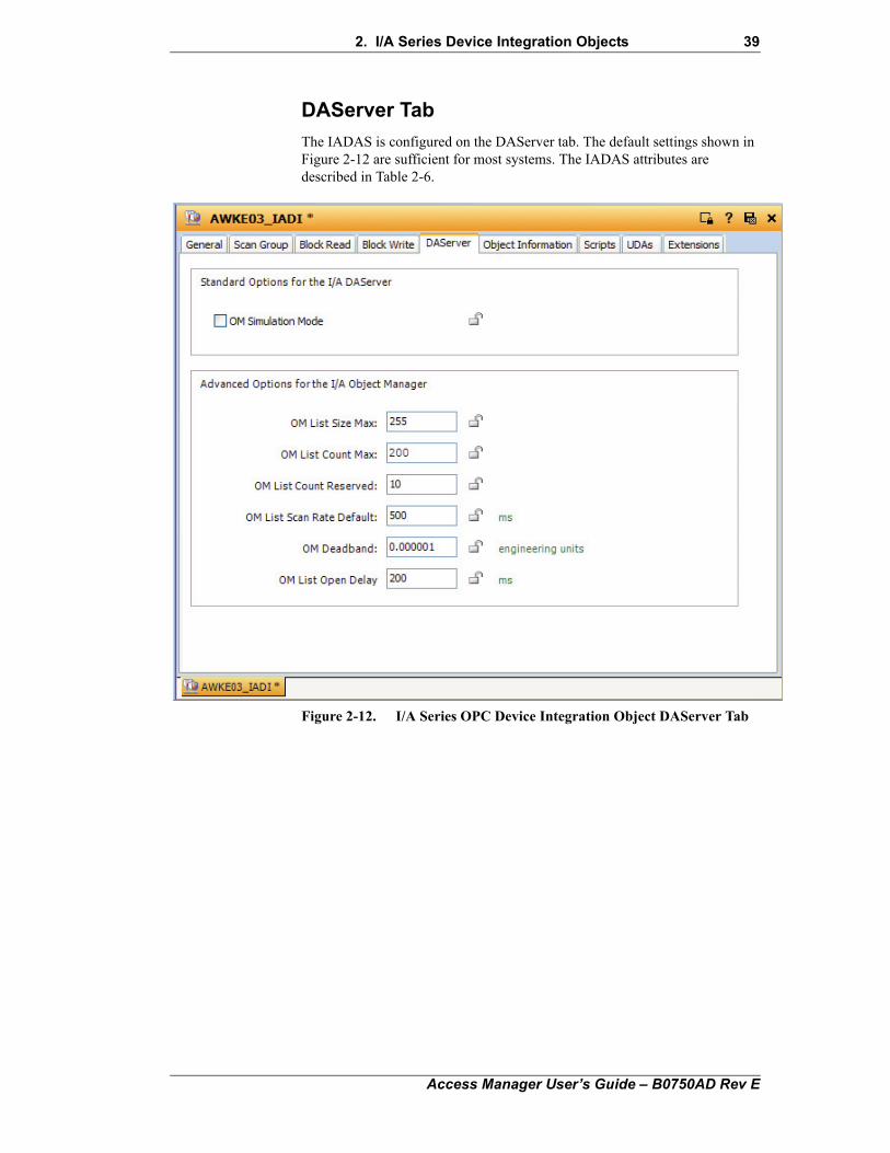
DAServer Tab
The IADAS is configured on the DAServer tab. The default settings shown in Figure 2-12 are sufficient for most systems. The IADAS attributes are described in Table 2-6.
Figure 2-12. I/A Series OPC Device Integration Object DAServer Tab
Access Manager User’s Guide – B0750AD Rev E
40 2. I/A Series Device Integration Objects
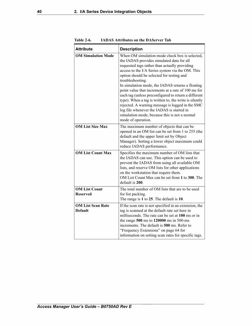
Table 2-6. IADAS Attributes on the DAServer Tab
Attribute Description
OM Simulation Mode When OM simulation mode check box is selected, the IADAS provides simulated data for all requested tags rather than actually providing access to the I/A Series system via the OM. This option should be selected for testing and troubleshooting.In simulation mode, the IADAS returns a floating point value that increments at a rate of 100 ms for each tag (unless preconfigured to return a different type). When a tag is written to, the write is silently rejected. A warning message is logged in the SMC log file whenever the IADAS is started in simulation mode, because this is not a normal mode of operation.
OM List Size Max The maximum number of objects that can be opened in an OM list can be set from 1 to 255 (the default and the upper limit set by Object Manager). Setting a lower object maximum could reduce IADAS performance.
OM List Count Max Specifies the maximum number of OM lists that the IADAS can use. This option can be used to prevent the IADAS from using all available OM lists, and reserve OM lists for other applications on the workstation that require them.OM List Count Max can be set from 1 to 300. The default is 200.
OM List Count Reserved
The total number of OM lists that are to be used for list packing.The range is 1 to 25. The default is 10.
OM List Scan Rate Default
If the scan rate is not specified in an extension, the tag is scanned at the default rate set here in milliseconds. The rate can be set at 100 ms or in the range 500 ms to 120000 ms in 500-ms increments. The default is 500 ms. Refer to “Frequency Extensions” on page 64 for information on setting scan rates for specific tags.
Access Manager User’s Guide – B0750AD Rev E
2. I/A Series Device Integration Objects 41
Scan Group TabThe Device Integration Object is preconfigured with a default scan group, and no additional scan groups need to be configured. Use the Scan Group tab (Table 2-7) to add optional scan groups to the object to organize tags on the client side. Note that these optional scan groups have no effect on the operation of the IADAS.
OM Deadband Specifies the default deadband (delta value) for items added to an OM list. The default is used if the item does not have a deadband specified in an extension (as described in “Deadband” on page 68). The deadband is the minimum change in the parameter value since the last update for another update to be sent to the client.The range is 0 or 0.000001 (default) to 1000000.0 engineering units.
OM List Open Delay The IADAS may need to open multiple OM lists in order to satisfy a set of item requests. This option specifies the time in milliseconds to delay before a subsequent OM open list is done. This delay places an upper limit on the frequency with which broadcasts are issued from this IADAS. The delay allows I/A Series stations time to process the broadcasts. This value should be increased if a display that has more than 255 tags is missing data.The range for OM List Open Delay is 0 to 12000 ms; the default is 200.
Table 2-7. Scan Group Tab
Field Description
Scan Group A unique name for a scan group in the IADAS from which you want to receive data.
To add a group: Click and type in the name of the group.To delete a group: Select the topic in the list and click
.
Update Interval The rate, in milliseconds, at which the object is to receive updated data values for the scan group. The default is 500.
Table 2-6. IADAS Attributes on the DAServer Tab (Continued)
Attribute Description
Access Manager User’s Guide – B0750AD Rev E
42 2. I/A Series Device Integration Objects
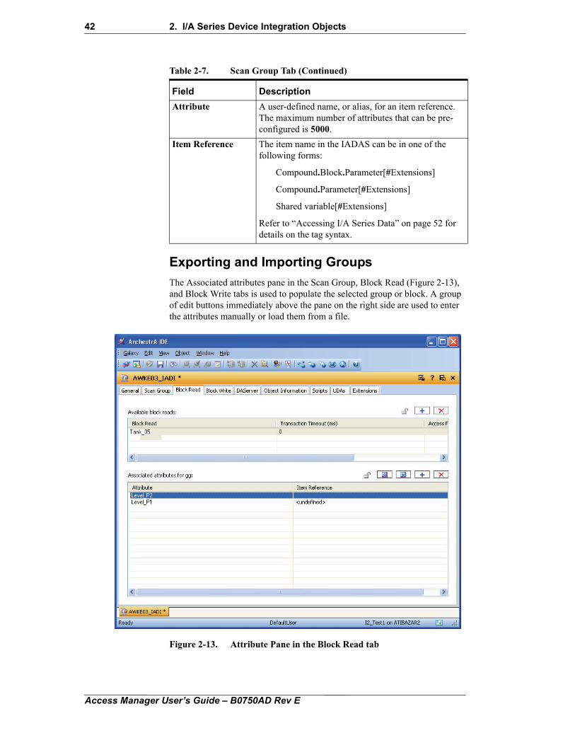
Exporting and Importing Groups
The Associated attributes pane in the Scan Group, Block Read (Figure 2-13), and Block Write tabs is used to populate the selected group or block. A group of edit buttons immediately above the pane on the right side are used to enter the attributes manually or load them from a file.
Figure 2-13. Attribute Pane in the Block Read tab
Attribute A user-defined name, or alias, for an item reference. The maximum number of attributes that can be pre-configured is 5000.
Item Reference The item name in the IADAS can be in one of the following forms:
Compound.Block.Parameter[#Extensions]
Compound.Parameter[#Extensions]
Shared variable[#Extensions]
Refer to “Accessing I/A Series Data” on page 52 for details on the tag syntax.
Table 2-7. Scan Group Tab (Continued)
Field Description
Access Manager User’s Guide – B0750AD Rev E
2. I/A Series Device Integration Objects 43
To add the associated attributes:
1. Click to make the next available row editable, and enter a unique name in the Attribute field.
2. Click in the Item Reference field to browse for and select the point in the I/A Series system.
Edit the Item Reference field to add extensions (as described in “Extensions” on page 58), if necessary.
Note Select an attribute and click to delete the attribute from the group or block.
3. Do the following to export the attribute list to a comma-separated value (*.csv) file:
a. Click to open a Windows Save As dialog box.
b. Use the dialog box to specify the file name and destination folder, and click Save.
4. Do the following to load attributes from a *.csv file:
a. Click to display a Windows Open dialog box.
b. Use the dialog box to specify the name and location of the source file, and click Open.
Block Read Tab
Use the Block Read tab (Figure 2-13) to configure a set of items for which values will be read from the IADAS in a single transaction. Table 2-8 describes the fields in the Block Read tab.
Table 2-8. Block Read Tab
Field Description
Block Read A unique name for a block read group.
To add a group: Click and type in the name of the group.To delete a group: Select the topic in the list and
click .
Transaction The time, in milliseconds, allowed for the block read transaction to be completed. The default value is 0 (no transaction timeout).
Access Path The OPC address path. The path syntax is specific to the type of OPC Server.
Access Manager User’s Guide – B0750AD Rev E
44 2. I/A Series Device Integration Objects
Block Write Tab
Use the Block Write tab to configure a set of items for which values will be written to the IADAS in a single transaction. Table 2-9 describes the fields in the Block Write tab.
Attribute A user-defined name for an item reference. This name is also known as the alias. The maximum number of attributes that can be preconfigured is 5000.
Item Reference The item name in the IADAS can be in one of the following forms:
Compound.Block.Parameter[#Extensions]
Compound.Parameter[#Extensions]
Shared variable[#Extensions]
Refer to “Accessing I/A Series Data” on page 52 for details on the tag syntax.
Table 2-9. Block Write Tab
Field Description
Block Write A unique name for a block write group.
To add a group: Click and type in the name of the group.To delete a group: Select the topic in the list and
click .
Transaction Timeout The time, in milliseconds, allowed for the block write transaction to be completed. The default value is 0 (no transaction timeout).
Access Path The OPC address path. The path syntax is specific to the type of OPC Server.
Attribute A user-defined name for an item reference. This name is also known as the alias. The maximum number of attributes that can be preconfigured is 5000.
Item Reference The item name in the IADAS can be in one of the following forms:
Compound.Block.Parameter[#Extensions]
Compound.Parameter[#Extensions]
Shared variable[#Extensions]
Refer to “Accessing I/A Series Data” on page 52 for details on the tag syntax.
Table 2-8. Block Read Tab
Field Description
Access Manager User’s Guide – B0750AD Rev E
2. I/A Series Device Integration Objects 45
IADAS User-Configurable Attribute InitializationIADAS user-configurable attributes are initialized when the IADAS is started. The following subsections explain how this is done by using the rule and configuration files.
Rule File
The IADAS rule file (IADAS.aarul) specifies that only one instance of the IADAS is allowed on any particular workstation, and defines the default attributes and values for that Server instance. The rule file is an XML file, but under normal circumstances and for most configurations, it should not be edited. Incorrect modification to this file will cause the server to malfunction.
Configuration File
The IADAS stores its configurable attributes in a configuration file (IADAS.aacfg). This file contains system variables and DeviceNnode configuration information. This file is read when the IADAS service is first started manually or when the associated I/A Series OPC Device Integration Object is deployed.
The configuration file is automatically updated when the I/A Series OPC Device Integration object is deployed or undeployed through the ArchestrA IDE. When the I/A Series OPC Device Integration object is deployed, a DeviceNode with the appropriate attributes is added to this file, and when the I/A Series Device Integration object is undeployed, the DeviceNode is removed.
This DeviceNode contains the configuration of the I/A Series OPC Device Integration object. The name of the DeviceNode will be the same as the name of the instance of the I/A Series OPC Device Integration object created in the IDE. The values for the DeviceNode’s attributes can be customized in the I/A Series OPC Device Integration object’s WinForm. Therefore, when deploying and starting the I/A Series OPC Device Integration object using the ArchestrA IDE, you should not modify this file.
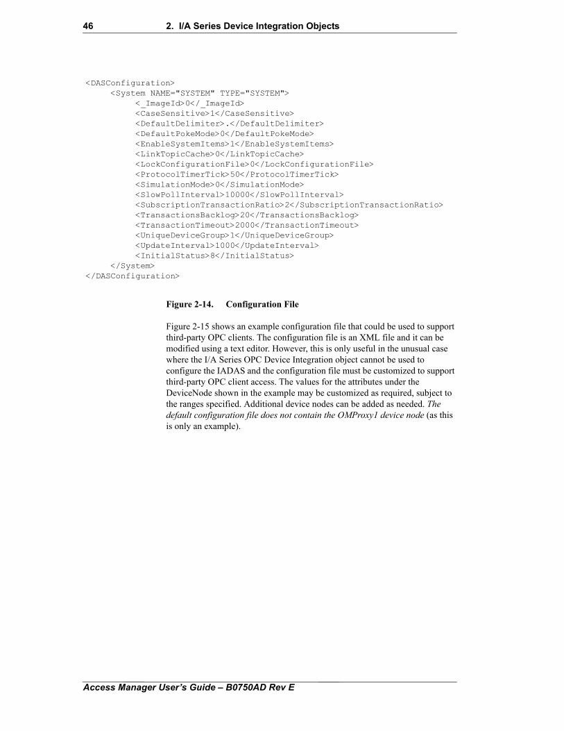
Figure 2-14 shows the default contents of the IADAS.cfg configuration file. The file looks like this before the I/A Series OPC Device Integration object is deployed.
Access Manager User’s Guide – B0750AD Rev E
46 2. I/A Series Device Integration Objects
Figure 2-14. Configuration File
Figure 2-15 shows an example configuration file that could be used to support third-party OPC clients. The configuration file is an XML file and it can be modified using a text editor. However, this is only useful in the unusual case where the I/A Series OPC Device Integration object cannot be used to configure the IADAS and the configuration file must be customized to support third-party OPC client access. The values for the attributes under the DeviceNode shown in the example may be customized as required, subject to the ranges specified. Additional device nodes can be added as needed. The default configuration file does not contain the OMProxy1 device node (as this is only an example).
<DASConfiguration><System NAME="SYSTEM" TYPE="SYSTEM">
<_ImageId>0</_ImageId><CaseSensitive>1</CaseSensitive><DefaultDelimiter>.</DefaultDelimiter><DefaultPokeMode>0</DefaultPokeMode><EnableSystemItems>1</EnableSystemItems><LinkTopicCache>0</LinkTopicCache><LockConfigurationFile>0</LockConfigurationFile><ProtocolTimerTick>50</ProtocolTimerTick><SimulationMode>0</SimulationMode><SlowPollInterval>10000</SlowPollInterval><SubscriptionTransactionRatio>2</SubscriptionTransactionRatio><TransactionsBacklog>20</TransactionsBacklog><TransactionTimeout>2000</TransactionTimeout><UniqueDeviceGroup>1</UniqueDeviceGroup><UpdateInterval>1000</UpdateInterval><InitialStatus>8</InitialStatus>
</System></DASConfiguration>
Access Manager User’s Guide – B0750AD Rev E
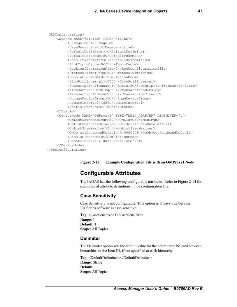
2. I/A Series Device Integration Objects 47
Figure 2-15. Example Configuration File with an OMProxy1 Node
Configurable Attributes
The IADAS has the following configurable attributes. Refer to Figure 2-14 for examples of attribute definitions in the configuration file.
Case Sensitivity
Case Sensitivity is not configurable. This option is always true because I/A Series software is case-sensitive.
Tag: <CaseSensitive>1</CaseSensitive>Range: 1Default: 1Scope: All Topics
Delimiter
The Delimiter option sets the default value for the delimiter to be used between hierarchies in the Item ID, if not specified at each hierarchy.
Tag: <DefaultDelimiter>.</DefaultDelimiter>Range: StringDefault: .Scope: All Topics
<DASConfiguration><System NAME="SYSTEM" TYPE="SYSTEM">
<_ImageId>0</_ImageId><CaseSensitive>1</CaseSensitive><DefaultDelimiter>.</DefaultDelimiter><DefaultPokeMode>0</DefaultPokeMode><EnableSystemItems>1</EnableSystemItems><LinkTopicCache>0</LinkTopicCache><LockConfigurationFile>0</LockConfigurationFile><ProtocolTimerTick>50</ProtocolTimerTick><SimulationMode>0</SimulationMode><SlowPollInterval>10000</SlowPollInterval><SubscriptionTransactionRatio>2</SubscriptionTransactionRatio><TransactionsBacklog>20</TransactionsBacklog><TransactionTimeout>2000</TransactionTimeout><UniqueDeviceGroup>1</UniqueDeviceGroup><UpdateInterval>1000</UpdateInterval><InitialStatus>8</InitialStatus>
</System><DeviceNode NAME="OMProxy1" TYPE="MESH_ADAPTER" DELIMITER=".">
<OmListCountMaximum>200</OmListCountMaximum><OmListScanRateDefault>500</OmListScanRateDefault><OmListSizeMaximum>255</OmListSizeMaximum><OmObjectDeadbandDefault>0.0000001</OmObjectDeadbandDefault><SimulationMode>0</SimulationMode><UpdateInterval>100</UpdateInterval>
</DeviceNode></DASConfiguration>
Access Manager User’s Guide – B0750AD Rev E
48 2. I/A Series Device Integration Objects
Initial Status
The Initial Status option enables the IADAS to return any OPC Quality after an item is activated or none at all. In the later case, the IADAS relies on the DAS Engine to provide the appropriate quality (see below). This option may be set to any desired OPC quality, using base 10 decimal notation. Since OPC Quality is usually documented in hexadecimal, a conversion to decimal is necessary before being used in the IADAS.AAcfg file. The default value for this option is BAD_NOTCONNECTED (<InitialStatus>8</InitialStatus>). If InitialStatus is set to BAD_WAITINGFORINITIALDATA (<InitialStatus>32</InitialStatus>) the IADAS will not force a status update, instead it will rely on the DAS Engine to update clients when the item becomes active. If Initial Status is set to <InitialStatus>288</InitialStatus>, the IADAS will force a status update, so BAD_WAITINGFORINITIALDATA can be forced in this way. Note that only the standard OPC quality and status bits are passed to the DAS Engine on initial updates. The vendor quality bits are not passed to ensure that the clients interpret them correctly.
Tag: < InitialStatus>10</ InitialStatus>Range: 0 to 65535Default: 8Scope: All Subscription Topics
Link Topic Cache
When the Link Topic Cache option is set to 0, group caches are created for items with identical ItemIDs. When set to 1, individual caches are created for each item.
Tag: <LinkTopicCache>0</LinkTopicCache>Range: 0 or 1Default: 0Scope: All Topics
OM List Count Maximum
OM List Count Maximum specifies the maximum number of OM lists that the IADAS can use. This option can be used to prevent the IADAS from using all available OM lists, and reserve OM lists for other applications requiring them.
Tag: <OmListCountMaximum>1</OmListCountMaximum>Range: 1 to 300Default: 210Scope: All Subscription Topics
OM List Count Reserve
OM List Count Reserve specifies the total number of OM lists that are to be used for list packing.
Tag: <OmListCountReserve>10</OmListCountReserve>Range: 1 to 25Default: 10Scope: All Subscription Topics
Access Manager User’s Guide – B0750AD Rev E
2. I/A Series Device Integration Objects 49
OM List Open Delay
The IADAS should open multiple OM lists in order to satisfy a set of item requests. This option specifies the delay in milliseconds before a subsequent OM open list is done. This delay places an upper limit on the frequency with which broadcasts are issued from this IADAS. The delay allows I/A Series stations time to process the broadcasts. This value should be increased if a display that has more than 255 tags is missing data.
Tag: <OmListOpenDelay>200</OmListOpenDelay>Range: 0 to 12000Default: 200Units: millisecondsScope: All Subscription Topics
OM List Scan Rate Default
If an OM List Scan Rate is not specified in a Frequency extension, the tag is scanned at the default rate set in OM List Scan Rate Default in milliseconds. See “Frequency Extensions” on page 64.
Tag: <OmListScanRateDefault>500</OmListScanRateDefault>Range: 100 or 500 to 120000 (in increments of 500 ms)Default: 500Units: millisecondsScope: Subscription Topics
OM List Size Maximum
OM List Size Maximum specifies the maximum number of objects allowed per OM list, and can be set from 1 to 255. Although you can reduce this number if required, setting a lower object maximum may reduce IADAS performance.
Tag: <OmListSizeMaximum>255</OmListSizeMaximum>Range: 1 to 255Default: 255Scope: All Subscription Topics
OM Object Deadband Default
OM Object Deadband Default specifies the default deadband (delta value) for items added to an OM list. The default is used if the item does not have a deadband specified in an extension (as described in “Deadband” on page 68). The deadband is the minimum change in the parameter value since the last update for another update to be sent to the client.
Tag: <OmObjectDeadbandDefault>0.000001</OmObjectDeadbandDefault>Range: 0 or 0.000001 to 1000000.0Default: 0.000001Units: Engineering UnitsScope: default Device Scan Group
Poll Rate Default
The Poll Rate Default option specifies the default poll rate for non connectable parameters.
Access Manager User’s Guide – B0750AD Rev E
50 2. I/A Series Device Integration Objects
Tag: <PollRateDefault>2000</PollRateDefault>Range: 500 to 86400000Default: 2000Units: millisecondsScope: Polled Parameters
Poll Rate Manual Factor
The Poll Rate Manual Factor option specifies the multiplication factor used to convert scan rates to poll rates for use with the #FM option. For example, if a parameter with a #FM500 option is a non connectable parameter and the PollRateManualFactor is 4, the parameter will be added to the poll publisher with time period of 500 ms * 4 = 2000 milliseconds.
Tag: <PollRateManualFactor>4</PollRateManualFactor >Range: 1 to 255Default: 4Scope: #FM option
Poll Rate Retry Factor
This option specifies the poll rate retry factor for failed OM get operations. When an OM get fails for a particular parameter, that parameter is retried at its original Poll Rate multiplied by the Poll Rate Retry Factor. For example, if a parameter that was polled at a 1000 ms interval with a Poll Rate Retry Factor of 60 ms, returned an error, it would not be retried for another 1000 * 60 = 60,000 ms or 1 minute.
Tag: <PollRateRetryFactor>60</PollRateRetryFactor>Range: 1 to 255Default: 60Scope: Polled Parameters
Poke Mode
This option is disabled and not configurable. The value is always 0, control mode. All data will be written in the order it is received.
Tag: <DefaultPokeMode>0</DefaultPokeMode>Range: 0Default: 0Scope: All Topics
Protocol Timer Tick
This option is disabled and not used.
Tag: <ProtocolTimerTick>50</ProtocolTimerTick>Range: 10 to 100000Default: 50Scope: not used
Simulation Mode
When Simulation Mode is 0, the IADAS accesses data from the I/A Series system. When Simulation Mode is 1, the IADAS provides simulated data for all requested tags, rather than actually providing access to the I/A Series
Access Manager User’s Guide – B0750AD Rev E
2. I/A Series Device Integration Objects 51
system via the OM. Simulation Mode is useful for testing and troubleshooting. A warning message is logged in the SMC log file whenever the IADAS is started in Simulation Mode indicating that this option is on.
Tag: <SimulationMode>0</SimulationMode>Range: 0 or 1Default: 0Scope: All Topics
Slow Poll Interval
This option specifies the slow poll interval (scan rate) in milliseconds for the default group and Device Scan Groups that do not have this attribute set.
Tag: <SlowPollInterval>10000</SlowPollInterval>Range: 0 to 100000Default: 10000Scope: All Topics
Subscription Transaction Ratio
The Subscription Transaction Ratio option specifies the ratio between subscription messages and transaction messages. This ratio lets the DAS Engine determine the priority of a transaction message. For the normal ratio of 2, if there is a continuous stack of transaction messages being sent by the client, the DAS Engine will send no more than 2 transaction messages before interleaving a subscription message. If no subscription message is due, that slot is given up, and the next transaction message is sent. This allows subscriptions to stay alive in the face of large transactions.
Tag: <SubscriptionTransactionRatio>2</SubscriptionTransactionRatio>Range: 1 to 1000Default: 2Scope: All Topics
Enable System Items
Setting the Enable System Items option to 1 enables system items. When set to 0, the DAS does not recognize items with the $SYS$ prefix as valid item names. The client will fail when trying to add items with these prefixes.
Tag: <EnableSystemItems>1</EnableSystemItems>Range: 0 or 1Default: 1Scope: All Topics
Transactions Backlog
The Transactions Backlog option specifies the number of completed transactions kept in the diagnostic viewer.
Tag: <TransactionsBacklog>20</TransactionsBacklog>Range: 0 to 50Default: 20Scope: Transaction Topics
Access Manager User’s Guide – B0750AD Rev E
52 2. I/A Series Device Integration Objects
Transaction Timeout
The Transaction Timeout option specifies the maximum time allowed in milliseconds for a message participating in a transaction to complete.
Tag: <TransactionTimeout>6000</TransactionTimeout>Range: 10 to 60000Default: 6000Scope: Transaction Topics
Unique Device Group
When Unique Device Group is set to 1, globally unique Device Scan Group names are required. When set to 0, identical Device Scan Group names are allowed on different hierarchies. Since the IADAS has only one hierarchy (one device node), setting this option to 0 will have no effect.
Tag: <UniqueDeviceGroup>1</UniqueDeviceGroup>Range: 0 or 1Default: 1Scope: All Topics
Update Interval
The Update Interval is the rate, in milliseconds, for all Message Processing. This is the rate at which the DAS Engine will scan for changes. The Update Interval should be set at a very high rate to ensure timely updates, but generally no faster than 100 ms. Note that the value can be decreased (that is, set to a faster rate) at run time using the $SYS$UpdateInterval system item. See “$sys$UpdateInterval (VT_UI4/Read, Write)” on page 56.
Tag: <UpdateInterval>100</UpdateInterval>Range: 0 to 100000Default: 100Scope: All Topics
Accessing I/A Series DataThis section describes the syntax used when constructing an OPC tag to access an I/A Series system parameter via the IADAS.
<Galaxy>:<DI Object>.<Scan Group>.IASeries.<Item>
The rules described in this section are used to form tag-strings using the I/A Series Browser. For additional information, refer to “DI & Extensions View” on page 12” and “Value Field” on page 14 in Chapter 1, “I/A Series Galaxy Browser”.
Access Manager User’s Guide – B0750AD Rev E
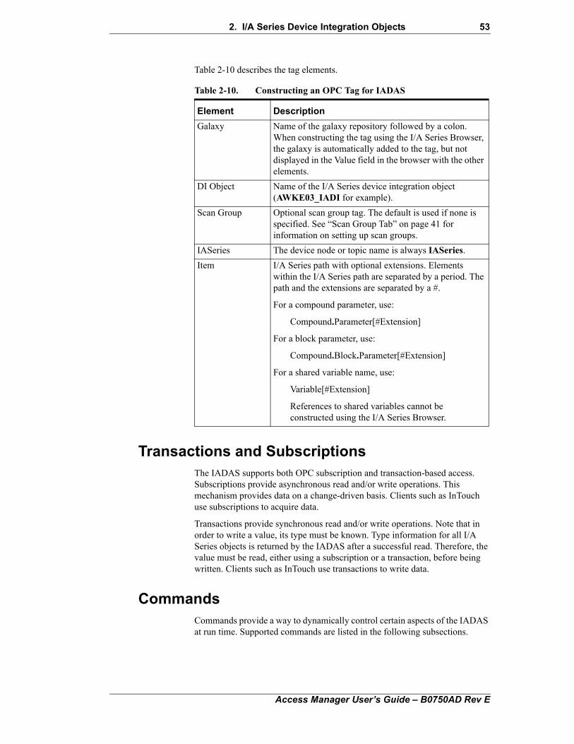
2. I/A Series Device Integration Objects 53
Table 2-10 describes the tag elements.
Transactions and SubscriptionsThe IADAS supports both OPC subscription and transaction-based access. Subscriptions provide asynchronous read and/or write operations. This mechanism provides data on a change-driven basis. Clients such as InTouch use subscriptions to acquire data.
Transactions provide synchronous read and/or write operations. Note that in order to write a value, its type must be known. Type information for all I/A Series objects is returned by the IADAS after a successful read. Therefore, the value must be read, either using a subscription or a transaction, before being written. Clients such as InTouch use transactions to write data.
CommandsCommands provide a way to dynamically control certain aspects of the IADAS at run time. Supported commands are listed in the following subsections.
Table 2-10. Constructing an OPC Tag for IADAS
Element Description
Galaxy Name of the galaxy repository followed by a colon. When constructing the tag using the I/A Series Browser, the galaxy is automatically added to the tag, but not displayed in the Value field in the browser with the other elements.
DI Object Name of the I/A Series device integration object (AWKE03_IADI for example).
Scan Group Optional scan group tag. The default is used if none is specified. See “Scan Group Tab” on page 41 for information on setting up scan groups.
IASeries The device node or topic name is always IASeries.
Item I/A Series path with optional extensions. Elements within the I/A Series path are separated by a period. The path and the extensions are separated by a #.
For a compound parameter, use:
Compound.Parameter[#Extension]
For a block parameter, use:
Compound.Block.Parameter[#Extension]
For a shared variable name, use:
Variable[#Extension]
References to shared variables cannot be constructed using the I/A Series Browser.
Access Manager User’s Guide – B0750AD Rev E
54 2. I/A Series Device Integration Objects
OnPollNow
When a value is written to the system item $SYS$PollNow in a subscription topic (device scan group), the server updates all items in that subscription topic. This is used to update items when the data is needed before the regular update occurs, which is governed by the device scan groups update interval.
This command forces a read of the OM list associated with the Device Scan Group, which will gather only the data that has changed since the OM list was last read (that is, dqlist). It does not cause an update of all of the data from the OM list (that is, omread), but only the data that has changed.
Store Settings
When a value is written to the system item $SYS$StoreSettings of a device scan group, the IADAS stores any changed settings in the configuration file.
Update Interval
When a value is written to the system item $SYS$UpdateInterval of a subscription topic (device scan group), the update interval is changed to that value.
System ItemsSystem items provide access to IADAS status and diagnostic information as well as special functions. This data can be acquired through subscription. Although system items appear to be ordinary data with respect to the client, these items are not acquired from the I/A Series system. System item values are generated through internal calculations, measurements, and tracking by the DAS Engine.
System Item Tags are case-insensitive in the IADAS. For example, $SYS$OMLISTCOUNTAVAILABLE and $Sys$OmListCountAvailable will address the same system item.
IADAS-Specific System Items
IADAS-specific system items include the following:
$sys$OmListCountAvailable (VT_I4/Read)
This is the number of OM lists that are available for use by the IADAS and subsequently the client. This number is OmListCountMaximum minus the number of reserved lists (OmListCountReserved) and the current number of OM lists opened by the IADAS.
Range: 0 to OmListCountMaximum, Default: N/A
$sys$OmListSizeMaximum(VT_I4/Read)
This is the maximum number of OM objects that will be added to an OM list before the list is considered full. This value is static because it is determined through configuration.
Range: 1 to 255, Default: N/A
Access Manager User’s Guide – B0750AD Rev E
2. I/A Series Device Integration Objects 55
$sys$OmListCountClientLimit(VT_I4/Read)
This is the total number of OM lists that will be used by the client, which is OmListCountReserved minus OmListCountMaximum, to allow for list packing. This value is static because it is determined through configuration.
Range: N/A, Value: OmListCountMaximum - OmListCountReserved, Default: N/A
Standard DAS System Items
Standard DAS system items include the following:
$sys$ActiveItemCount (VT_UI4/Read)
This indicates the number of active items added to a specific device scan group by all clients.
Range: Number of active items on a device scan group
$sys$ErrorCode (VT_I4/Read)
This is a detailed error code of the communication state of the device.
Range:
>=0 – Good status (0 is the default state – connected, >0 is some device state like connecting, initializing, etc.)
<0 – Error status (value indicates the error)
The server-specific code signals this state to the DAS Engine after evaluating protocol access return codes and mapping them to server-specific error codes.
$sys$ErrorCount (VT_UI4/Read)
This indicates the number of device transactions or subscriptions currently in error on a specific device scan group.
Range: Number of current errors on a device scan group
$sys$ErrorText (VT_BSTR/Read)
This is a detailed error string of the communication state of the device.
Range: Descriptive text for the communication state corresponding to the error code
The DAS Engine will call the server-specific code, passing the error code and locale ID to the server to retrieve the error text value.
$sys$ItemCount (VT_UI4/Read)
This indicates the number of items (both active and inactive) added to a specific device scan group by all clients.
Range: Number of items on a device scan group
$sys$Licensed (VT_BOOL/Read)
This reflects the licensed state of the DAServer. When this is false, the DAServer will stop updating values, and new items cannot be added. This
Access Manager User’s Guide – B0750AD Rev E
56 2. I/A Series Device Integration Objects
value will be true by default. The IADAS has no licensing mechanism independent of ArchestrA licensing.
Range:
True (-1) when licensed.
False (0) when not licensed.
$sys$MaxInterval (VT_UI4/Read)
This is the maximum device update interval that has been measured for a specific device group.
Range: Maximum device update interval for a device scan group, in milliseconds
$sys$PollNow (VT_BOOL/Read, Write)
This allows the client to cause all device subscription messages to become due for a specific device scan group. Writing a value of ‘1’ will initiate the poll; all other values are ignored. This item will always return a value of ‘0’ when read.
Range: Always zero
$sys$ReadComplete (VT_I4/Read, Write)
This is set to a nonzero value when a read transaction completes for a specific device scan group. It can be written by the client to zero, and the change back to nonzero will indicate read-complete.
Range: Nonzero when a read completes for a device scan group, zero when written by client
$sys$Status (VT_BOOL/Read)
This is a binary status indication of the connection state to the device (hierarchy level) to which the item is attached. The status can be good even if individual items have errors.
Range:
• True (-1): IADAS connection to the device is intact.
• False (0): Error communicating with the device.
The server-specific code signals this state to the DAS Engine after evaluating protocol access return codes.
$sys$StoreSettings (VT_UI4/Read, Write)
This allows the client to store changed settings in the configuration file for a specific device scan group. Writing a value of ‘1’ will store the settings for the device scan group; all other values are ignored. This item will always return a value of ‘0’ when read.
Range: Always zero
$sys$UpdateInterval (VT_UI4/Read, Write)
This is the update interval for messages (see section Update Interval for more information).
Range: Update interval in milliseconds
Access Manager User’s Guide – B0750AD Rev E
2. I/A Series Device Integration Objects 57
$sys$WriteComplete (VT_I4/Read, Write)
This is set to a nonzero value when a write transaction completes for a specific device scan group. It can be written by the client to zero, and the change back to nonzero will indicate write-complete.
Range: Nonzero when a write completes for a device scan group, zero when written by client.
Tag ItemsTag Items provide clients with the ability to obtain the I/A Series parameter name and extension as a string without performing any additional parsing operations. This data can be acquired through a transaction or subscription mechanism.
Note Because subscriptions provide data on a change-driven basis and the string value returned will never change, the usefulness of the subscription mechanism is minimal.
Although tag items appear to be ordinary data with respect to the client, the values are not acquired from the I/A Series system. Tag Item values are generated from the tag name itself. The syntax is as follows (two forms are supported):
Galaxy:IADI.IASeries.$tag$COMP.BLOCK.PARAM#Extensions
or
Galaxy:IADI.IASeries.$tag$.COMP.BLOCK.PARAM#Extensions
Either of the above tags will return the following:
COMP.BLOCK.PARAM#Extensions
DI Object LogsThis section describes the procedure for using the Log Flag Editor to capture I/A Series OPC Device Integration Object log messages. The SMC provides the ability to capture I/A Series OPC Device Integration Object log messages. Logging may be configured by using the Log Flag Editor, as shown in Figure 2-16. Under normal operating conditions, only the following Log Flags need be enabled: Error, Warning, and Info. When troubleshooting a general problem, it is often useful to enable Trace. Verbose can be used in combination with any Log Flag. This Log Flag will allow the I/A Series OPC Device Integration Object to log more detailed information; however, it may produce a very large number of log messages. Use Security log flag to trace security information provided by the I/A Series Security Provider. Use Security log flag to trace security information provided by the I/A Series Security Provider.
Access Manager User’s Guide – B0750AD Rev E
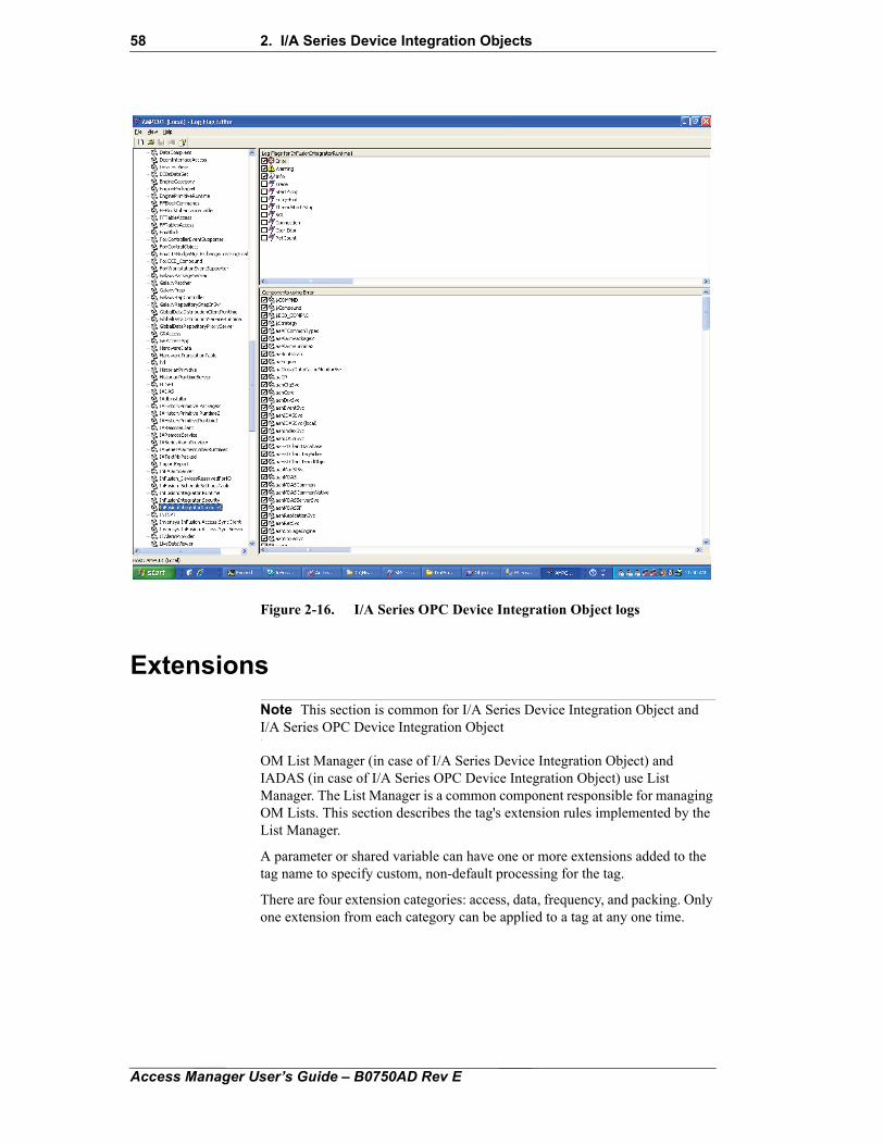
58 2. I/A Series Device Integration Objects
Figure 2-16. I/A Series OPC Device Integration Object logs
Extensions
Note This section is common for I/A Series Device Integration Object and I/A Series OPC Device Integration Object
OM List Manager (in case of I/A Series Device Integration Object) and IADAS (in case of I/A Series OPC Device Integration Object) use List Manager. The List Manager is a common component responsible for managing OM Lists. This section describes the tag's extension rules implemented by the List Manager.
A parameter or shared variable can have one or more extensions added to the tag name to specify custom, non-default processing for the tag.
There are four extension categories: access, data, frequency, and packing. Only one extension from each category can be applied to a tag at any one time.
Access Manager User’s Guide – B0750AD Rev E
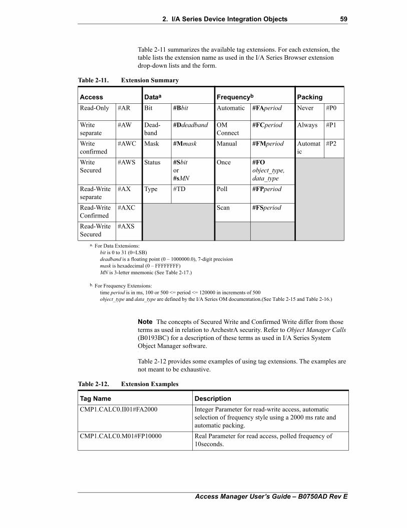
2. I/A Series Device Integration Objects 59
Table 2-11 summarizes the available tag extensions. For each extension, the table lists the extension name as used in the I/A Series Browser extension drop-down lists and the form.
Note The concepts of Secured Write and Confirmed Write differ from those terms as used in relation to ArchestrA security. Refer to Object Manager Calls (B0193BC) for a description of these terms as used in I/A Series System Object Manager software.
Table 2-12 provides some examples of using tag extensions. The examples are not meant to be exhaustive.
Table 2-11. Extension Summary
Access Dataa Frequencyb Packing
Read-Only #AR Bit #Bbit Automatic #FAperiod Never #P0
Write separate
#AW Dead-band
#Ddeadband OM Connect
#FCperiod Always #P1
Write confirmed
#AWC Mask #Mmask Manual #FMperiod Automatic
#P2
Write Secured
#AWS Status #Sbitor#sMN
Once #FOobject_type,data_type
Read-Write separate
#AX Type #TD Poll #FPperiod
Read-Write Confirmed
#AXC Scan #FSperiod
Read-Write Secured
#AXS
a. For Data Extensions:bit is 0 to 31 (0=LSB)deadband is a floating point (0 – 1000000.0), 7-digit precisionmask is hexadecimal (0 – FFFFFFFF)MN is 3-letter mnemonic (See Table 2-17.)
b. For Frequency Extensions:time period is in ms, 100 or 500 <= period <= 120000 in increments of 500object_type and data_type are defined by the I/A Series OM documentation.(See Table 2-15 and Table 2-16.)
Table 2-12. Extension Examples
Tag Name Description
CMP1.CALC0.II01#FA2000 Integer Parameter for read-write access, automatic selection of frequency style using a 2000 ms rate and automatic packing.
CMP1.CALC0.M01#FP10000 Real Parameter for read access, polled frequency of 10seconds.
Access Manager User’s Guide – B0750AD Rev E
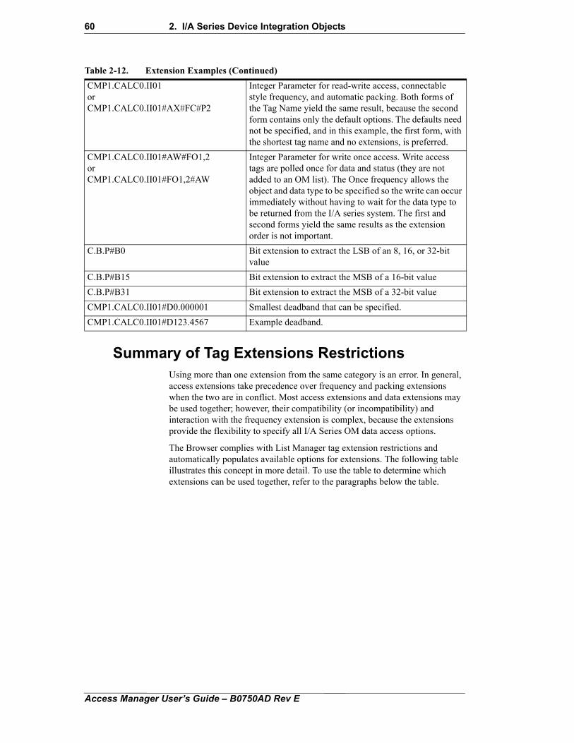
60 2. I/A Series Device Integration Objects
Summary of Tag Extensions RestrictionsUsing more than one extension from the same category is an error. In general, access extensions take precedence over frequency and packing extensions when the two are in conflict. Most access extensions and data extensions may be used together; however, their compatibility (or incompatibility) and interaction with the frequency extension is complex, because the extensions provide the flexibility to specify all I/A Series OM data access options.
The Browser complies with List Manager tag extension restrictions and automatically populates available options for extensions. The following table illustrates this concept in more detail. To use the table to determine which extensions can be used together, refer to the paragraphs below the table.
CMP1.CALC0.II01orCMP1.CALC0.II01#AX#FC#P2
Integer Parameter for read-write access, connectable style frequency, and automatic packing. Both forms of the Tag Name yield the same result, because the second form contains only the default options. The defaults need not be specified, and in this example, the first form, with the shortest tag name and no extensions, is preferred.
CMP1.CALC0.II01#AW#FO1,2orCMP1.CALC0.II01#FO1,2#AW
Integer Parameter for write once access. Write access tags are polled once for data and status (they are not added to an OM list). The Once frequency allows the object and data type to be specified so the write can occur immediately without having to wait for the data type to be returned from the I/A series system. The first and second forms yield the same results as the extension order is not important.
C.B.P#B0 Bit extension to extract the LSB of an 8, 16, or 32-bit value
C.B.P#B15 Bit extension to extract the MSB of a 16-bit value
C.B.P#B31 Bit extension to extract the MSB of a 32-bit value
CMP1.CALC0.II01#D0.000001 Smallest deadband that can be specified.
CMP1.CALC0.II01#D123.4567 Example deadband.
Table 2-12. Extension Examples (Continued)
Access Manager User’s Guide – B0750AD Rev E
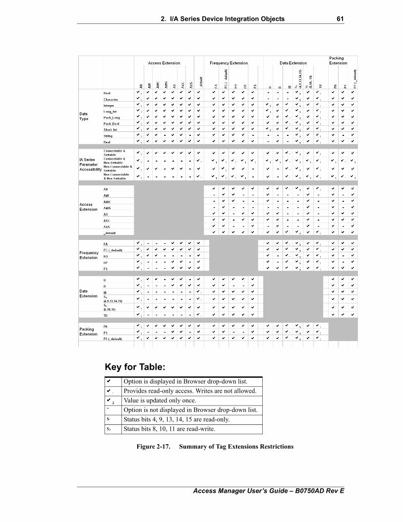
2. I/A Series Device Integration Objects 61
Figure 2-17. Summary of Tag Extensions Restrictions
Key for Table:
Option is displayed in Browser drop-down list.
Provides read-only access. Writes are not allowed.
Value is updated only once.
Option is not displayed in Browser drop-down list.
Status bits 4, 9, 13, 14, 15 are read-only.
Status bits 8, 10, 11 are read-write.
Access Manager User’s Guide – B0750AD Rev E
62 2. I/A Series Device Integration Objects
Use the table in Figure 2-17 to determine which extensions are available and which can be used together.
First, select a parameter from the Galaxy Browser. The parameter selected limits the initial set of available options based on the values in the Data Type and the I/A Series Parameter Accessibility rows. Only those options (shown in the columns) with a check in both the appropriate Data Type and I/A Series Parameter Accessibility rows are visible in the Browser’s drop-down lists.
For example, selecting the PERIOD parameter (a short integer data type that is non connectable and non settable) initially causes the browser to display the following extensions. If you follow the “Short_Int” row in the Data Type category while following the “Non Connectable & Non Settable” row in the I/A Series Parameter Accessibility category, you see that:
• The AR and default access extensions will be shown in the browser, because the AR access extension column has checks in the “Short_Int” and “Non Connectable & Non-Settable” rows, and the default access extension column also has checks in each of these rows.
• The FA, FC, FO, and FP frequency extensions will be shown in the browser, because these frequency extensions all have checks in both the “Short_Int” and “Non Connectable & Non Settable” rows.
• Similarly, the B, M, S1, S2, and TD data extensions will be shown in the browser, because these data extension columns all have checks in both the “Short_Int” and “Non Connectable & Non Settable” rows. However, the D data extension will not be shown in the browser because the D data extension column does not have a check in the “Non Connectable & Non Settable” row.
• Finally, the P0, P1, and P2 packing extensions will be shown in the browser for the same reason.
If non-default functioning is desired, choose a valid access, frequency, data, or packing extension (columns) to use. Choosing a column may further restrict which additional options are visible in the browser. To determine which extensions are available, read down the chosen column. Note that visible options are determined by the logical “and” of the initial set with this next set of restrictions. Continue to choose additional options if desired.
Example 1:
For the PIDA parameter HOLIND (a connectable, non settable, boolean), choose “Bool” and “Connectable & Non Settable” rows. Looking across the “Bool” row, you can see that selecting this parameter removes the B, D, and M options because this is a boolean data type. Looking across the “Connectable & Non Settable” row, you can see that AW, AWC, AWS, AX, AXC, and AXS options are removed because this is a connectable, non-settable parameter. Choosing the FP column further restricts the options by removing the P1 option (follow the FP column down). The AR, S, and TD options are still available to choose if desired.
Example 2:
For the PIDA parameter FFTBLK (a connectable, settable, long integer), choose “Long_Int” and “Connectable & Settable” rows. Looking across the “Long_Int” row, you can see that selecting this parameter does not restrict the selection of any additional options; all the options are checked.
Access Manager User’s Guide – B0750AD Rev E
2. I/A Series Device Integration Objects 63
(However, some options are read-only.) Choosing the AXS column restricts the options by removing FO, FP, B, M, certain Status bits, and the P1 options from the browser’s drop-down list.
Access ExtensionsAccess extensions specify the access privilege (read-only, write, or read-write) and write method (separate, confirmed, or secured) for data access.
The write method defaults to separate if no other write method is specified. If an access extension is not specified, the access privilege is governed by the data extension, in combination with the OM data type. If no data extension is specified or the specified data extension does not limit the access privilege, the access privilege defaults to read-write (#AX).
The access extensions are listed in Table 2-13.
Notes
1. If the secured write method is specified for an object that is unsecurable, no objects within the same OM list as the unsecurable object are accessible and their status remains bad or pending. This is an OM limitation.
2. The List Manager writes secured objects one at a time so there is no performance improvement over separate writes.
3. If the confirmed write method is specified, the List Manager makes a synchronous write to I/A, waiting for a response from the destination.
Table 2-13. Access Extensions
Browser Selection Form Description
Read Only #AR Values are read (change-driven updates) via an OM list. The value may not be written to tags with this extension. Attempts to write to the tag result in an OM error code of -7, reported in the SMC.
Write Separate #AW Values may be written. Writes are done using the OM set API. Value and status may be read initially using the OM get API, as I/A Series type information is required for writing. Thereafter, the value may not be updated (see notes below).
Write Confirmed #AWC As AW, except that values are written using the OM set_confirm API.
Write Secured #AWS Values may be written. Writes are done using the OM omwrite API (see note 1 below).
Read-Write #AX Values are read (change-driven updates) via an OM list and may be written. Writes are done using the OM set API.
Read-Write Confirmed
#AXC Values are read (change-driven updates) via an OM list and may be written. Writes are done using the OM set_confirm API.
Read-Write Secured #AXS Values are read (change-driven updates) via an OM list and may be written. Writes are done using the OM omwrite API (see note 1 below).
Access Manager User’s Guide – B0750AD Rev E
64 2. I/A Series Device Integration Objects
4. The write separate method (#AW) does not require the destination to respond. In this case, writes are faster and success is assumed if the local OM returns success. However, in the case of #AW, whether or not the destination accepted the write may be unknown, as the value may not be updated. If updates are desired, use the #AX extension (which is the default).
5. Tags with the #AW, #AWC, or #AWS extensions will not have their values updated periodically unless another tag with read options (#AR, #AX, #AXC, #AXS) and the same path name was added previously to the List Manager. In this case, the data and status of the new tag will be updated when the other tag is updated. This is because the List Manager is designed to reuse compatible existing objects, rather than creating new objects for each item added.
6. Tags with a secured write extension (#AXS or #AWS) are never multiplexed (shared) with other tags with the same path, as the purpose of a secured write is to connect one parameter to another and allow writes only through that parameter. When a tag with a secured write extension is added, it is always placed on a new OM list. Note that if the Tag is identical with another existing tag, the List Manager treats it as the same Tag and does not provide it to the List Manager. This violates the I/A Series concept of the secured write, but ArchestrA software is designed to work this way.
7. Write secured extensions (#AWS, #AXS) cannot be used with the #B, #M, or #T extension, as the OM List API does not support writing bit masks or type. If these extensions are used, reads may be possible but the writes will not contain the necessary mask information.
8. Write secured extensions (#AWS, #AXS) cannot be used with the #FP or #FO extensions, because these Frequency modes do not use OM lists.
9. Write secured extensions (#AWS, #AXS) cannot be used with the #FA or #FC extension if the I/A Series parameters are not connectable, since non-connectable parameters cannot be written through OM lists.
10. Tags with a write secured extension (#AWS, #AXS) cannot be packed. These parameters work as if the #P0 extension were specified. If parameters with write secured extensions have compatible options and are added at the same time, they are placed on the same OM list (which has the same effect as list packing).
If an Access extension is specified that is incompatible with a Data extension, an error is logged in the SMC. In some cases, incompatible extensions will prevent data access. In other cases, it will only restrict data access. For example, if a write-only access privilege was specified for a read-only status bit as in #AW#sSEC, the data would not be written. However, if a read-write access privilege was specified for a read-only status bit as in #AX#sSEC, data would be read but not written.
Frequency ExtensionsThe frequency extension specifies the minimum rate at which data is read from the OM and the method of data access. When a frequency extension is not specified, the List Manager uses the rate specified in OM List Scan Rate
Access Manager User’s Guide – B0750AD Rev E
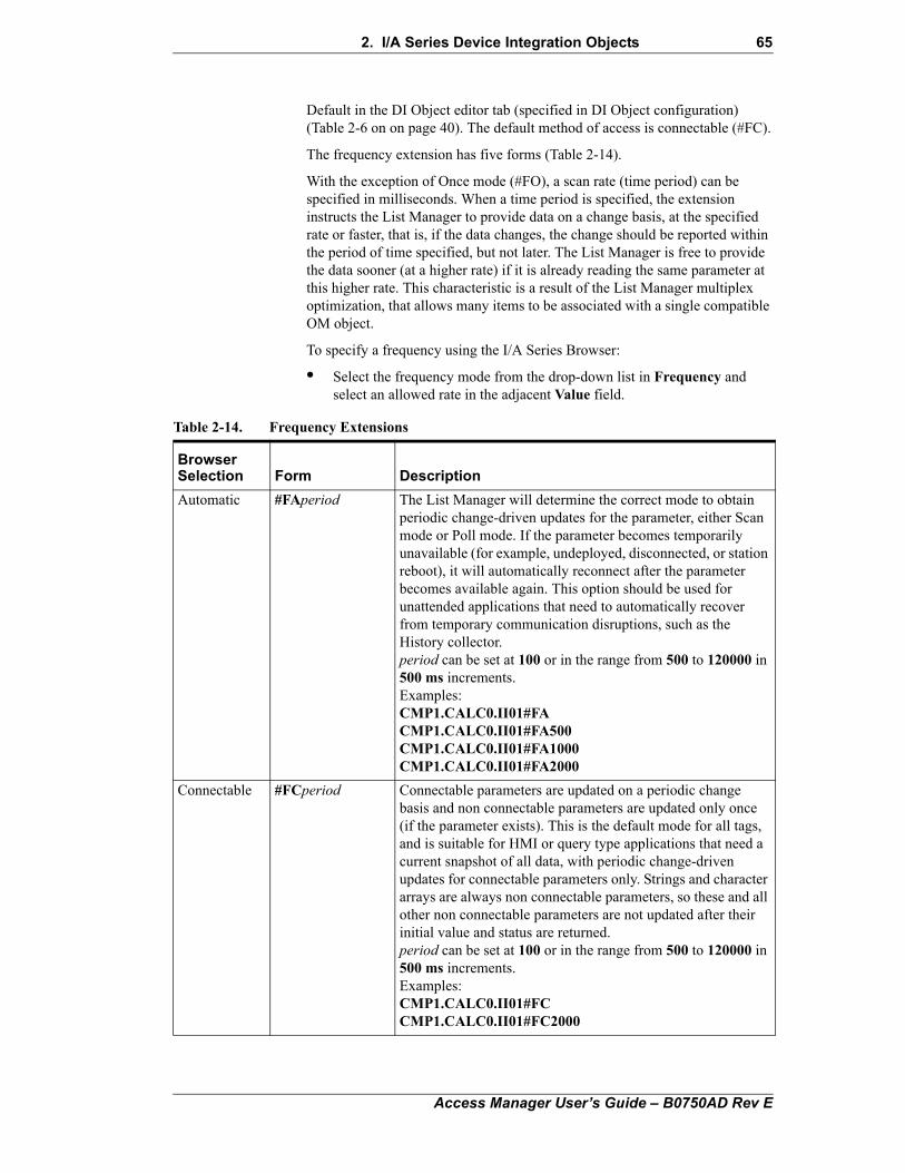
2. I/A Series Device Integration Objects 65
Default in the DI Object editor tab (specified in DI Object configuration) (Table 2-6 on on page 40). The default method of access is connectable (#FC).
The frequency extension has five forms (Table 2-14).
With the exception of Once mode (#FO), a scan rate (time period) can be specified in milliseconds. When a time period is specified, the extension instructs the List Manager to provide data on a change basis, at the specified rate or faster, that is, if the data changes, the change should be reported within the period of time specified, but not later. The List Manager is free to provide the data sooner (at a higher rate) if it is already reading the same parameter at this higher rate. This characteristic is a result of the List Manager multiplex optimization, that allows many items to be associated with a single compatible OM object.
To specify a frequency using the I/A Series Browser:
• Select the frequency mode from the drop-down list in Frequency and select an allowed rate in the adjacent Value field.
Table 2-14. Frequency Extensions
Browser Selection Form Description
Automatic #FAperiod The List Manager will determine the correct mode to obtain periodic change-driven updates for the parameter, either Scan mode or Poll mode. If the parameter becomes temporarily unavailable (for example, undeployed, disconnected, or station reboot), it will automatically reconnect after the parameter becomes available again. This option should be used for unattended applications that need to automatically recover from temporary communication disruptions, such as the History collector. period can be set at 100 or in the range from 500 to 120000 in 500 ms increments.Examples:CMP1.CALC0.II01#FACMP1.CALC0.II01#FA500CMP1.CALC0.II01#FA1000CMP1.CALC0.II01#FA2000
Connectable #FCperiod Connectable parameters are updated on a periodic change basis and non connectable parameters are updated only once (if the parameter exists). This is the default mode for all tags, and is suitable for HMI or query type applications that need a current snapshot of all data, with periodic change-driven updates for connectable parameters only. Strings and character arrays are always non connectable parameters, so these and all other non connectable parameters are not updated after their initial value and status are returned. period can be set at 100 or in the range from 500 to 120000 in 500 ms increments.Examples:CMP1.CALC0.II01#FCCMP1.CALC0.II01#FC2000
Access Manager User’s Guide – B0750AD Rev E
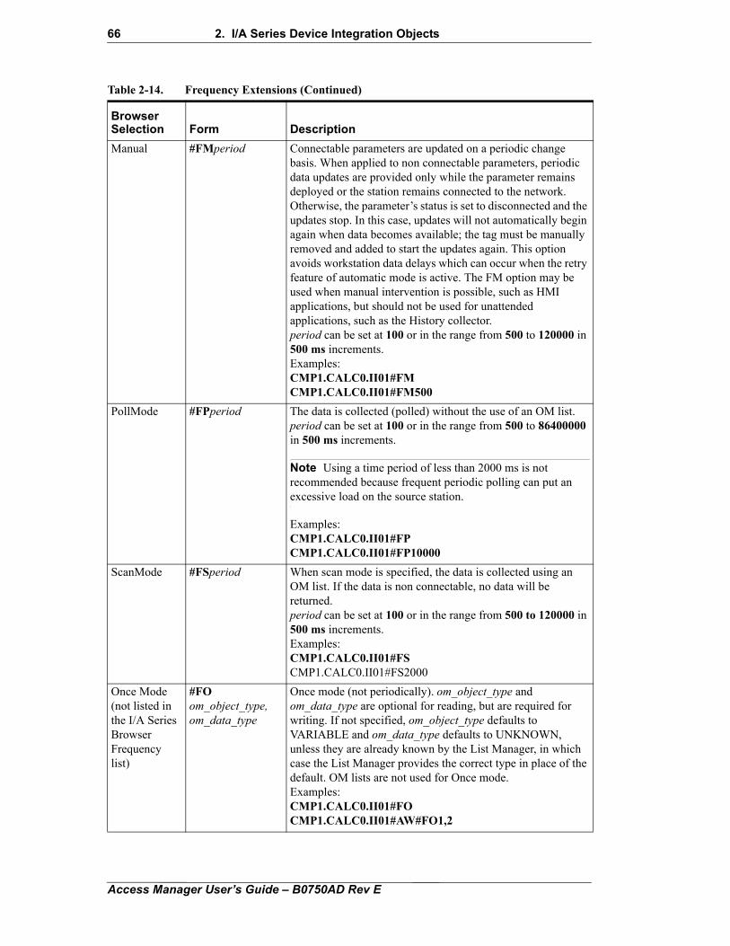
66 2. I/A Series Device Integration Objects
Manual #FMperiod Connectable parameters are updated on a periodic change basis. When applied to non connectable parameters, periodic data updates are provided only while the parameter remains deployed or the station remains connected to the network. Otherwise, the parameter’s status is set to disconnected and the updates stop. In this case, updates will not automatically begin again when data becomes available; the tag must be manually removed and added to start the updates again. This option avoids workstation data delays which can occur when the retry feature of automatic mode is active. The FM option may be used when manual intervention is possible, such as HMI applications, but should not be used for unattended applications, such as the History collector. period can be set at 100 or in the range from 500 to 120000 in 500 ms increments.Examples:CMP1.CALC0.II01#FMCMP1.CALC0.II01#FM500
PollMode #FPperiod The data is collected (polled) without the use of an OM list. period can be set at 100 or in the range from 500 to 86400000 in 500 ms increments.
Note Using a time period of less than 2000 ms is not recommended because frequent periodic polling can put an excessive load on the source station.
Examples:CMP1.CALC0.II01#FPCMP1.CALC0.II01#FP10000
ScanMode #FSperiod When scan mode is specified, the data is collected using an OM list. If the data is non connectable, no data will be returned.period can be set at 100 or in the range from 500 to 120000 in 500 ms increments.Examples:CMP1.CALC0.II01#FSCMP1.CALC0.II01#FS2000
Once Mode(not listed in the I/A Series Browser Frequency list)
#FOom_object_type,om_data_type
Once mode (not periodically). om_object_type and om_data_type are optional for reading, but are required for writing. If not specified, om_object_type defaults to VARIABLE and om_data_type defaults to UNKNOWN, unless they are already known by the List Manager, in which case the List Manager provides the correct type in place of the default. OM lists are not used for Once mode.Examples:CMP1.CALC0.II01#FOCMP1.CALC0.II01#AW#FO1,2
Table 2-14. Frequency Extensions (Continued)
Browser Selection Form Description
Access Manager User’s Guide – B0750AD Rev E
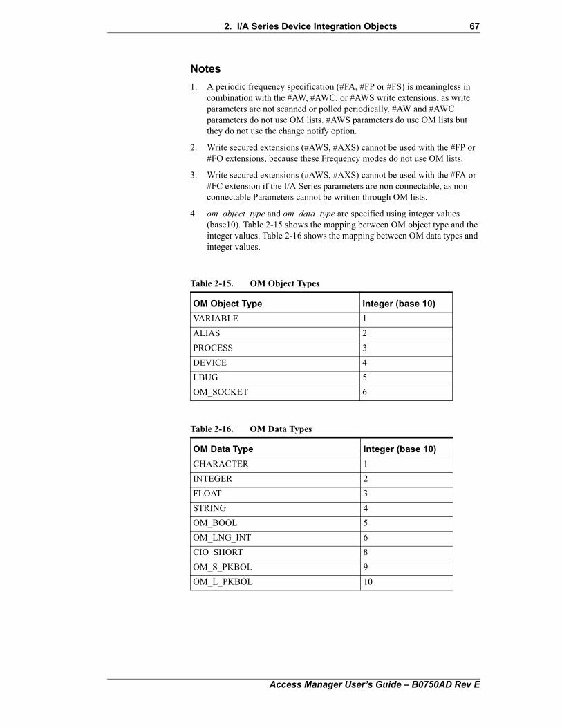
2. I/A Series Device Integration Objects 67
Notes
1. A periodic frequency specification (#FA, #FP or #FS) is meaningless in combination with the #AW, #AWC, or #AWS write extensions, as write parameters are not scanned or polled periodically. #AW and #AWC parameters do not use OM lists. #AWS parameters do use OM lists but they do not use the change notify option.
2. Write secured extensions (#AWS, #AXS) cannot be used with the #FP or #FO extensions, because these Frequency modes do not use OM lists.
3. Write secured extensions (#AWS, #AXS) cannot be used with the #FA or #FC extension if the I/A Series parameters are non connectable, as non connectable Parameters cannot be written through OM lists.
4. om_object_type and om_data_type are specified using integer values (base10). Table 2-15 shows the mapping between OM object type and the integer values. Table 2-16 shows the mapping between OM data types and integer values.
Table 2-15. OM Object Types
OM Object Type Integer (base 10)
VARIABLE 1
ALIAS 2
PROCESS 3
DEVICE 4
LBUG 5
OM_SOCKET 6
Table 2-16. OM Data Types
OM Data Type Integer (base 10)
CHARACTER 1
INTEGER 2
FLOAT 3
STRING 4
OM_BOOL 5
OM_LNG_INT 6
CIO_SHORT 8
OM_S_PKBOL 9
OM_L_PKBOL 10
Access Manager User’s Guide – B0750AD Rev E
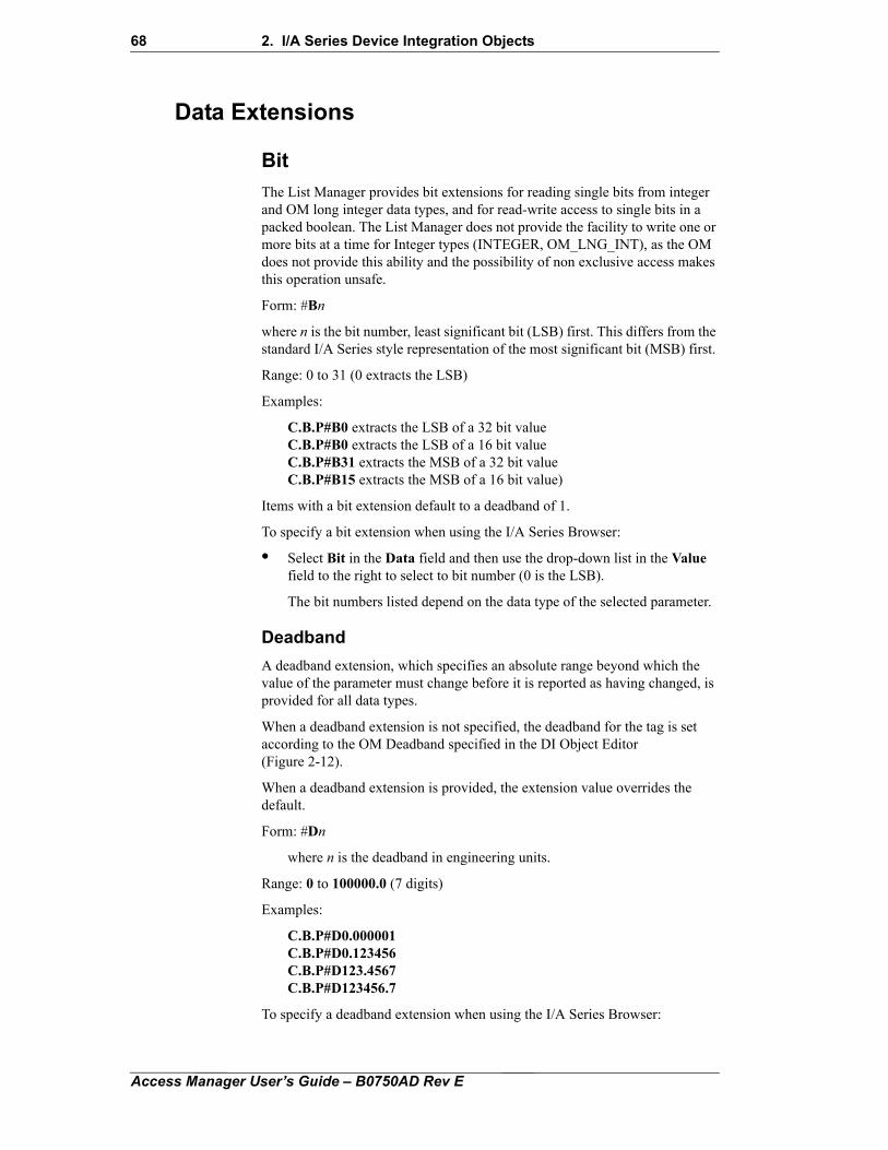
68 2. I/A Series Device Integration Objects
Data Extensions
Bit
The List Manager provides bit extensions for reading single bits from integer and OM long integer data types, and for read-write access to single bits in a packed boolean. The List Manager does not provide the facility to write one or more bits at a time for Integer types (INTEGER, OM_LNG_INT), as the OM does not provide this ability and the possibility of non exclusive access makes this operation unsafe.
Form: #Bn
where n is the bit number, least significant bit (LSB) first. This differs from the standard I/A Series style representation of the most significant bit (MSB) first.
Range: 0 to 31 (0 extracts the LSB)
Examples:
C.B.P#B0 extracts the LSB of a 32 bit valueC.B.P#B0 extracts the LSB of a 16 bit valueC.B.P#B31 extracts the MSB of a 32 bit valueC.B.P#B15 extracts the MSB of a 16 bit value)
Items with a bit extension default to a deadband of 1.
To specify a bit extension when using the I/A Series Browser:
• Select Bit in the Data field and then use the drop-down list in the Value field to the right to select to bit number (0 is the LSB).
The bit numbers listed depend on the data type of the selected parameter.
Deadband
A deadband extension, which specifies an absolute range beyond which the value of the parameter must change before it is reported as having changed, is provided for all data types.
When a deadband extension is not specified, the deadband for the tag is set according to the OM Deadband specified in the DI Object Editor (Figure 2-12).
When a deadband extension is provided, the extension value overrides the default.
Form: #Dn
where n is the deadband in engineering units.
Range: 0 to 100000.0 (7 digits)
Examples:
C.B.P#D0.000001C.B.P#D0.123456C.B.P#D123.4567C.B.P#D123456.7
To specify a deadband extension when using the I/A Series Browser:
Access Manager User’s Guide – B0750AD Rev E
2. I/A Series Device Integration Objects 69
• Select Deadband in the Data field and enter the data in the Value field to the right.
Notes
1. The deadband is a floating-point value within a specified range. A deadband of 0 indicates that the value of the parameter should be updated every scan cycle.
2. A deadband applied to a CHARACTER or a STRING data type is ignored, as both CHARACTER and STRING data types are represented as strings in the List Manager.
3. The smallest fractional deadband that can be configured is 0.000001, as there is a limit of 7 digits in the configuration file.
4. Deadband is the delta value and is only meaningful for connectable parameters that are accessed via an OM list. Deadband is ignored when used in combination with #FP or #FO and when the #FA or #FC option is used to access a non connectable parameter.
5. For OM_BOOL types (digital I/O) use a deadband of 1 (#D1). Bit extensions (#B) default to a deadband of 1.
Mask
The mask extension provides the ability to read integer and packed boolean values (INTEGER, OM_LNG_INT, CIO_SHORT, OM_S_PKBOL, OM_L_PKBOL) while ignoring bits within the value that are not specified within the mask. If the value provided for the mask is out of range, the mask is set to 0 and no masking is done. This is equivalent to specifying FFFFFFFF as a mask. Mask extensions are ignored when writing values.
Form: Mmask
where mask denotes the bit positions to be read.
Range: 1 (reads the LSB only) to 0xFFFFFFFF (reads all bits)
To specify a bit extension when using the I/A Series Browser:
• Select Mask in the Data field and then enter the mask in the Value field (1 to FFFFFFFF).
Status
The status extension allows read and read-write access to selected bits in the I/A Series status word. Tags with a status extension return a Boolean value corresponding to the I/A Series value status of the parameter, instead of returning the parameter value. Likewise, writing a Boolean value to a tag with a status extension sets the I/A Series value status of the parameter, not the value of the parameter assuming the status bit has read-write access.
There are two forms for specifying a status extension:
#Sbit where bit is the bit number as listed in Table 2-17.
#sMN where MN is the mnemonic of the status bit as shown Table 2-17.
Access Manager User’s Guide – B0750AD Rev E
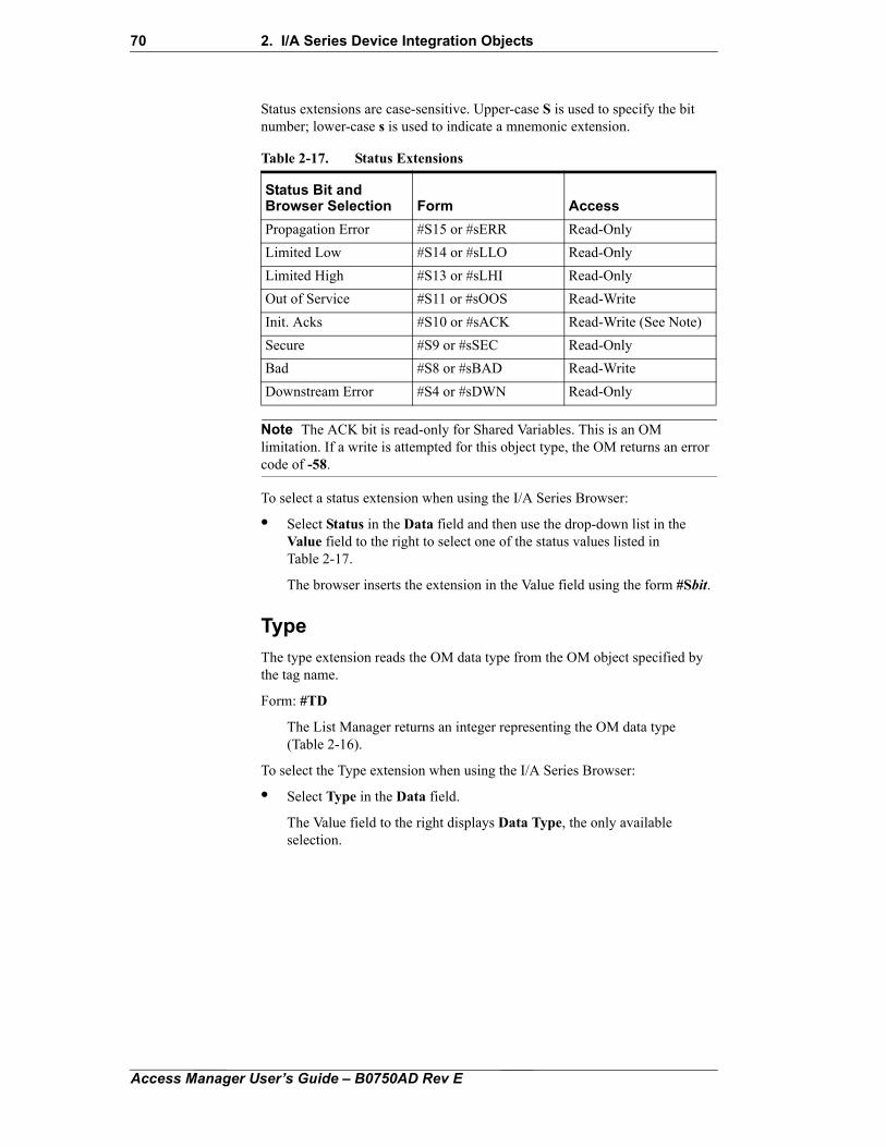
70 2. I/A Series Device Integration Objects
Status extensions are case-sensitive. Upper-case S is used to specify the bit number; lower-case s is used to indicate a mnemonic extension.
Note The ACK bit is read-only for Shared Variables. This is an OM limitation. If a write is attempted for this object type, the OM returns an error code of -58.
To select a status extension when using the I/A Series Browser:
• Select Status in the Data field and then use the drop-down list in the Value field to the right to select one of the status values listed in Table 2-17.
The browser inserts the extension in the Value field using the form #Sbit.
Type
The type extension reads the OM data type from the OM object specified by the tag name.
Form: #TD
The List Manager returns an integer representing the OM data type (Table 2-16).
To select the Type extension when using the I/A Series Browser:
• Select Type in the Data field.
The Value field to the right displays Data Type, the only available selection.
Table 2-17. Status Extensions
Status Bit and Browser Selection Form Access
Propagation Error #S15 or #sERR Read-Only
Limited Low #S14 or #sLLO Read-Only
Limited High #S13 or #sLHI Read-Only
Out of Service #S11 or #sOOS Read-Write
Init. Acks #S10 or #sACK Read-Write (See Note)
Secure #S9 or #sSEC Read-Only
Bad #S8 or #sBAD Read-Write
Downstream Error #S4 or #sDWN Read-Only
Access Manager User’s Guide – B0750AD Rev E
2. I/A Series Device Integration Objects 71
Packing ExtensionsThe packing extensions (Table 2-18) specify the data organization in an OM list. The default packing mode is #P2, Automatic packing, which is sufficient for most clients.
Note Tags with a write secured extension (#AWS, #AXS) cannot be packed. These parameters work as if the #P0 extension were specified. If parameters with write secured extensions have compatible options and are added at the same time, they are placed on the same OM list that has the same effect as list packing.
Table 2-18. Packing Extensions
Browser Selection Form Description
None #P0 No packing is performed. The List Manager adds the parameter to a new or compatible currently filling OM list. The server does not add the parameter to an OM list that is already open. This represents the lowest latency (that is, best response) mode. Applications that require consistent performance should use this mode. However, when the OM List Count Maximum set in the DI Object Editor tab (Figure 2-12) is reached, no additional parameters need to be added to the List Manager. This mode may result in the under utilization of OM lists if fewer than 255 items are added per list.
Always #P1 Always adds the parameter to a compatible currently filling OM list or to an open compatible OM list if it has space; otherwise, a new OM list is created. This mode maximizes list packing at the expense of the time needed to copy the contents of one list to another. Applications that require a large amount of data throughput, where startup latency is not important, such as a Historian, should select this mode.
Automatic #P2 Automatic packing adds the parameter to a new or compatible currently filling OM list. If the OM List Count Maximum set in the DAServer tab (Figure 2-12) has been reached, the parameter is added to an OM list that is already open. This is the default mode of operation and provides an adaptive function, combining the other two modes. Applications that require good performance and scalability should use this mode. The performance degrades after the OM List Count Maximum set in the DI Object Editor tab (Figure 2-12) has been reached.
Access Manager User’s Guide – B0750AD Rev E

72 2. I/A Series Device Integration Objects
Access Manager User’s Guide – B0750AD Rev E
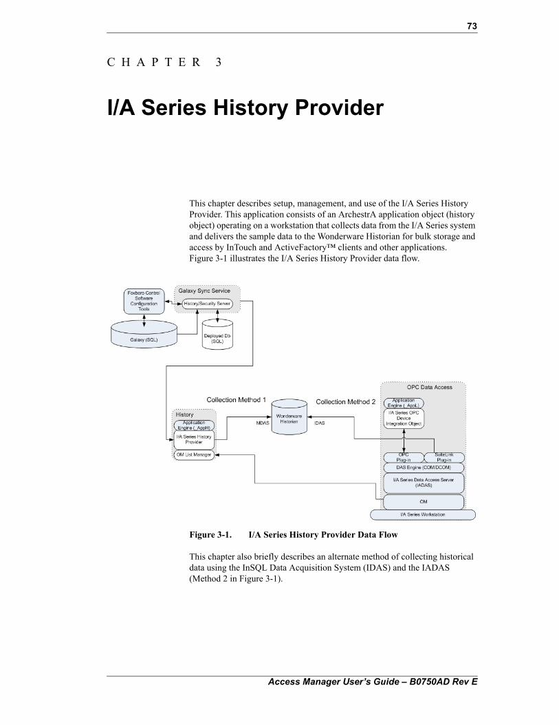
73
C H A P T E R 3
I/A Series History Provider
This chapter describes setup, management, and use of the I/A Series History Provider. This application consists of an ArchestrA application object (history object) operating on a workstation that collects data from the I/A Series system and delivers the sample data to the Wonderware Historian for bulk storage and access by InTouch and ActiveFactory™ clients and other applications. Figure 3-1 illustrates the I/A Series History Provider data flow.
Figure 3-1. I/A Series History Provider Data Flow
This chapter also briefly describes an alternate method of collecting historical data using the InSQL Data Acquisition System (IDAS) and the IADAS (Method 2 in Figure 3-1).
Access Manager User’s Guide – B0750AD Rev E
74 3. I/A Series History Provider
Contents
• I/A Series History Provider Installation
• Wonderware Historian Installation
• Configuring Historian Collectors
• Configuring Historian Connections
• Starting and Stopping the Wonderware Historian
• Verifying History Storage
• History Object Log flags
I/A Series History Provider InstallationThe I/A Series History Provider application object is installed and deployed on applicable FCS workstations (as required by the selected configuration) as part of the FCS installation.
Note It is recommended that you do not deploy the I/A Series History Provider application object if the workstation is not to be used for data collection. Undeploying the object reduces load on the workstation and the Galaxy Sync Service, which must periodically respond to all I/A Series History Provider application objects that are on scan.
During the installation process, the user is prompted to designate the Wonderware Historian Server that is to provide the bulk storage. The designation can also be made later or changed as described in the next section.
The history object is instantiated as <letterbug>_Hist in the area <letterbug>_AreaH under the application engine <letterbug>_AppH, where <letterbug> is the workstation name.
The Deployment view in Figure 3-2 shows the history application engine, area, and application object for the workstation AWKE03.
Access Manager User’s Guide – B0750AD Rev E
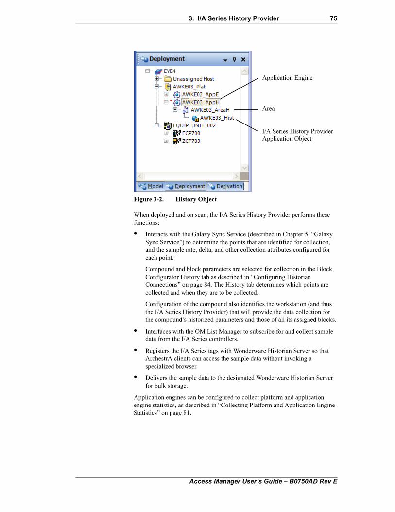
3. I/A Series History Provider 75
Figure 3-2. History Object
When deployed and on scan, the I/A Series History Provider performs these functions:
• Interacts with the Galaxy Sync Service (described in Chapter 5, “Galaxy Sync Service”) to determine the points that are identified for collection, and the sample rate, delta, and other collection attributes configured for each point.
Compound and block parameters are selected for collection in the Block Configurator History tab as described in “Configuring Historian Connections” on page 84. The History tab determines which points are collected and when they are to be collected.
Configuration of the compound also identifies the workstation (and thus the I/A Series History Provider) that will provide the data collection for the compound’s historized parameters and those of all its assigned blocks.
• Interfaces with the OM List Manager to subscribe for and collect sample data from the I/A Series controllers.
• Registers the I/A Series tags with Wonderware Historian Server so that ArchestrA clients can access the sample data without invoking a specialized browser.
• Delivers the sample data to the designated Wonderware Historian Server for bulk storage.
Application engines can be configured to collect platform and application engine statistics, as described in “Collecting Platform and Application Engine Statistics” on page 81.
Application Engine
Area
I/A Series History ProviderApplication Object
Access Manager User’s Guide – B0750AD Rev E
76 3. I/A Series History Provider
Wonderware Historian InstallationThe Wonderware Historian is typically installed by selecting the predefined Wonderware Historian Server configuration in the FCS installation program. Refer to Foxboro Control Software Installation Guide (B0750RA) for more information on installation.
The installation program can also install the Wonderware Historian on a non- I/A Series station that meets minimum hardware and software requirements for the Wonderware Historian Server. Refer to Foxboro Control Software Deployment Guide (B0750BA) for more information on sizing.
Note The Historian must have a Fox Administrator account, with the associated fixed password. The FCS installation program automatically creates this account.
Note The I/A Series History Provider requires the Historian system time to be synchronized with I/A Series system time. This is done automatically by the master timekeeper for all I/A Series stations. For non- I/A Series stations, either an alternate means of time synchronization must be used or history data must be collected using the IDAS instead of the I/A Series History Provider.
Hardware RequirementsThe minimum hardware requirements for the Wonderware Historian are based on the tag count and the anticipated data throughput. If the Historian’s tag count exceeds 70,000 tags or if the anticipated data storage rate exceeds 30,000 values per second, a more powerful server should be used or a proportional number of I/A Series AW70 servers should be added to the system. As multiprocessor and multicore I/A Series AW70 servers are not currently available, selecting a more powerful server requires that it be located on a separate network, because only I/A Series stations can be connected to the Mesh network. Consult the IndustrialSQL Server 9.0 Installation Guide for guidance on selecting a non-I/A Series server.
Configuring Historian CollectorsThere are two ways to collect historical data in an FCS Enterprise Control System:
Method 1: Use the I/A Series History Provider to collect data through the OM List Manager and forward the data to the Wonderware Historian Server. This is the preferred method because:
• All configuration is done with the FCS Configuration Tools. Setting up historization of parameters is done as part of the configuration of their respective blocks and compounds, either at the template or instance level.
• This method takes advantage of the store-and-forward capability of the collecting workstation and can be configured to use dual redundant collecting workstations.
Access Manager User’s Guide – B0750AD Rev E
3. I/A Series History Provider 77
Method 2: Use the IDAS to collect the data from the IADAS or another DA server. Use this method:
• To sample shared variables on I/A Series stations.
• When the time used to provide the value’s timestamp is not synchronized with the time used by the Wonderware Historian, that is, the time is not synchronized throughout the system.
There is usually no need to collect the same parameter using both methods.
Collection Using the I/A Series History Provider
Method 1 is to configure Historical Data Collection workstation to send historical data to the Wonderware Historian. This is done from within the FCS Configuration Tools, using the Block Configurator for each compound or block containing the parameters you want to historize. Figure 3-1 identifies Method 1 and shows the I/A Series History Provider data flow.
The FCS installation program will install the software necessary to collect historical data on each workstation.
To start collecting historical data:
1. Identify all the workstations you want to use for collecting historical data.
Note Each collecting workstation can collect at most 30,000 tags. If more tags are needed, a proportional number of collecting workstations will be required. Refer to Foxboro Control Software Deployment Guide (B0750BA) for additional sizing considerations.
2. Specify which collecting workstation will collect the parameters associated with each compound.
In the FCS Configuration Tools, edit each compound that contains parameters (and/or blocks with parameters) that you want to have historized. Assign the letterbug of one collecting workstation to each compound. If you have configured redundant collecting workstations, select the letterbug of the primary workstation of the redundant pair. See “Configuring Historian Connections” on page 84 for additional information.
3. Specify each parameter to be historized.
In the FCS Configuration Tools, edit each compound or block, and, for each parameter you want to historize, check the History Enabled check box and specify the scan rate, dead band, and other collection attributes. See “Configuring Historian Connections” on page 84 for additional information.
4. Deploy each compound and block.
When the compounds and blocks are deployed, the collecting workstations start collecting data from the I/A Series stations and forward it to the Wonderware Historian for storage. This activity will continue until the compounds and blocks are undeployed.
Access Manager User’s Guide – B0750AD Rev E
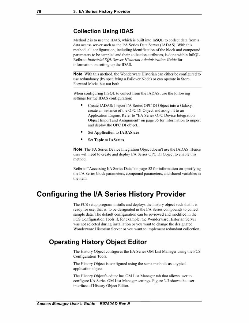
78 3. I/A Series History Provider
Collection Using IDAS
Method 2 is to use the IDAS, which is built into InSQL to collect data from a data access server such as the I/A Series Data Server (IADAS). With this method, all configuration, including identification of the block and compound parameters to be sampled and their collection attributes, is done within InSQL. Refer to Industrial SQL Server Historian Administration Guide for information on setting up the IDAS.
Note With this method, the Wonderware Historian can either be configured to use redundancy (by specifying a Failover Node) or can operate in Store Forward Mode, but not both.
When configuring InSQL to collect from the IADAS, use the following settings for the IDAS configuration:
• Create IADAS: Import I/A Series OPC DI Object into a Galaxy, create an instance of the OPC DI Object and assign it to an Application Engine. Refer to “I/A Series OPC Device Integration Object Import and Assignment” on page 35 for information to import and deploy the OPC DI object.
• Set Application to IADAS.exe
• Set Topic to IASeries
Note The I/A Series Device Integration Object doesn't use the IADAS. Hence user will need to create and deploy I/A Series OPC DI Object to enable this method.
Refer to “Accessing I/A Series Data” on page 52 for information on specifying the I/A Series block parameters, compound parameters, and shared variables in the item.
Configuring the I/A Series History ProviderThe FCS setup program installs and deploys the history object such that it is ready for use, that is, to be designated in the I/A Series compounds to collect sample data. The default configuration can be reviewed and modified in the FCS Configuration Tools if, for example, the Wonderware Historian Server was not selected during installation or you want to change the designated Wonderware Historian Server or you want to implement redundant collection.
Operating History Object EditorThe History Object configures the I/A Series OM List Manager using the FCS Configuration Tools.
The History Object is configured using the same methods as a typical application object
The History Object’s editor has OM List Manager tab that allows user to configure I/A Series OM List Manager settings. Figure 3-3 shows the user interface of History Object Editor.
Access Manager User’s Guide – B0750AD Rev E
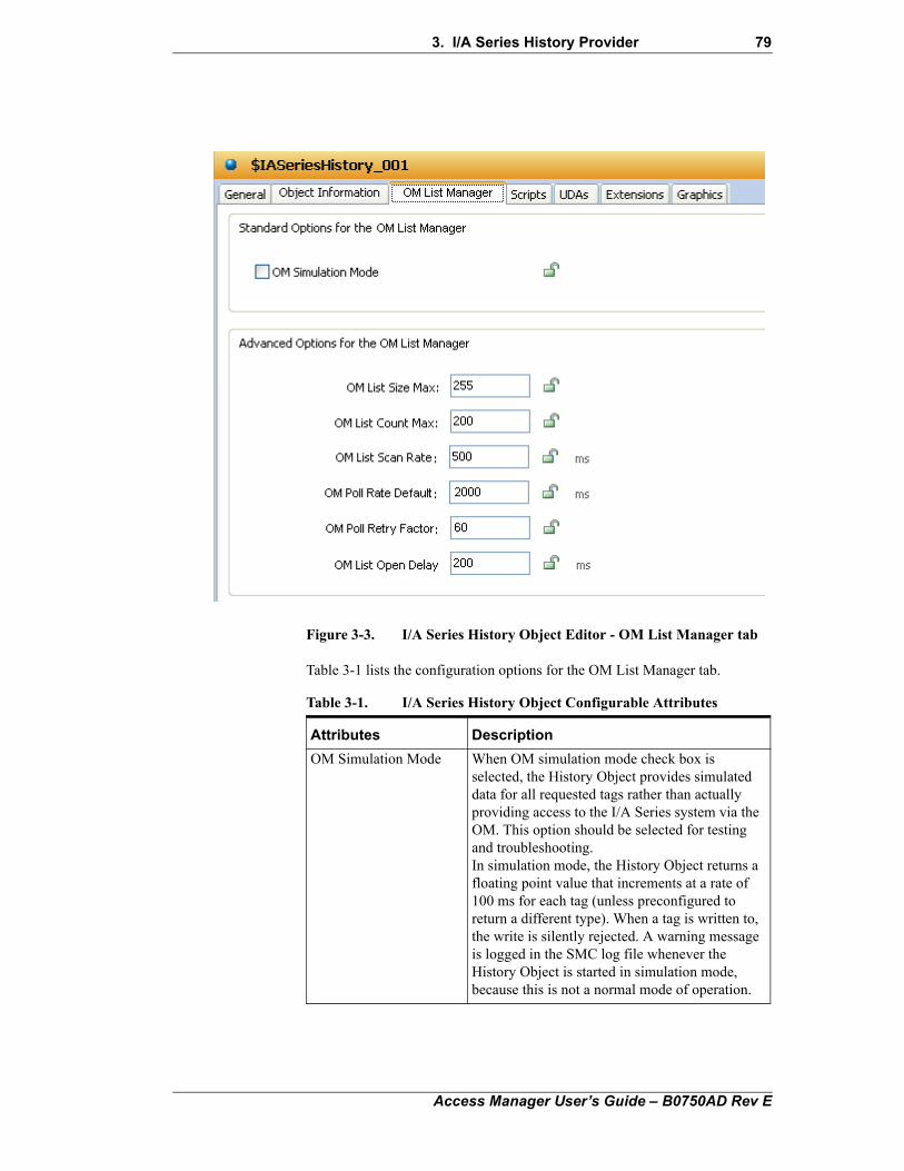
3. I/A Series History Provider 79
Figure 3-3. I/A Series History Object Editor - OM List Manager tab
Table 3-1 lists the configuration options for the OM List Manager tab.
Table 3-1. I/A Series History Object Configurable Attributes
Attributes Description
OM Simulation Mode When OM simulation mode check box is selected, the History Object provides simulated data for all requested tags rather than actually providing access to the I/A Series system via the OM. This option should be selected for testing and troubleshooting.In simulation mode, the History Object returns a floating point value that increments at a rate of 100 ms for each tag (unless preconfigured to return a different type). When a tag is written to, the write is silently rejected. A warning message is logged in the SMC log file whenever the History Object is started in simulation mode, because this is not a normal mode of operation.
Access Manager User’s Guide – B0750AD Rev E
80 3. I/A Series History Provider
Designating a Wonderware Historian ServerTo designate a Wonderware Historian Server:
1. Double-click the history application engine (AWKE03_AppH in Figure 3-2) in the Deployment view to display the General tab in the editor window (Figure 3-4).
2. Make sure that Enable storage to historian check box is selected.
OM List Size Max This option specifies the maximum number of tags allowed per OM List. This number can be reduced if required. Note that reducing theOM List Size Max will reduce the capacity ofthe I/A Series History Object.Range: 1 to 255, Default: 255.
OM List CountMax
This option specifies the maximum number of OM Lists that the I/A Series History Object will use. This is useful if otherapplications on the Workstation require OM Lists.Range: 1 to 300, Default: 200.
OM List Scan Rate This option specifies the OM List scan rate for items that are added without explicitly specifyinga scan rate with the Frequency Extension.Range: 100 to 2000 (in increments of500 ms), Default: 100, Units: milliseconds.
OM Poll Rate Default This option specifies the default poll rate for nonconnectable parameters.Range: 500 to 86,400,000, Default: 2,000, Units:milliseconds.
OM Poll Rate Retry Factor
This option specifies the Poll rate retry factor forfailed omget. When an OM get fails for aparticular parameter, that parameter is retried atits original Poll Rate multiplied by thePollRateRetryFactor. For example, if a parameterthat was Polled at a 1,000 ms interval with aPollRateRetryFactor of 60 ms, returned an error,it would not be retried for another 1000 * 60 =60,000 ms or 1 minute.Range: 1 to 255, Default: 60, Scope: PolledParameters
OM List Open Delay The I/A Series History Object may need to open multiple OM Lists in order to satisfy a set of Item requests. This option specifies the time in milliseconds to delay before a subsequent OM Open is done. This delay places an upper limit on the frequency in which broadcasts are issued from this History Object, which allows the stations time to process the broadcasts.Range: 0 to 12000, Default: 200, Units:milliseconds.
Table 3-1. I/A Series History Object Configurable Attributes
Access Manager User’s Guide – B0750AD Rev E
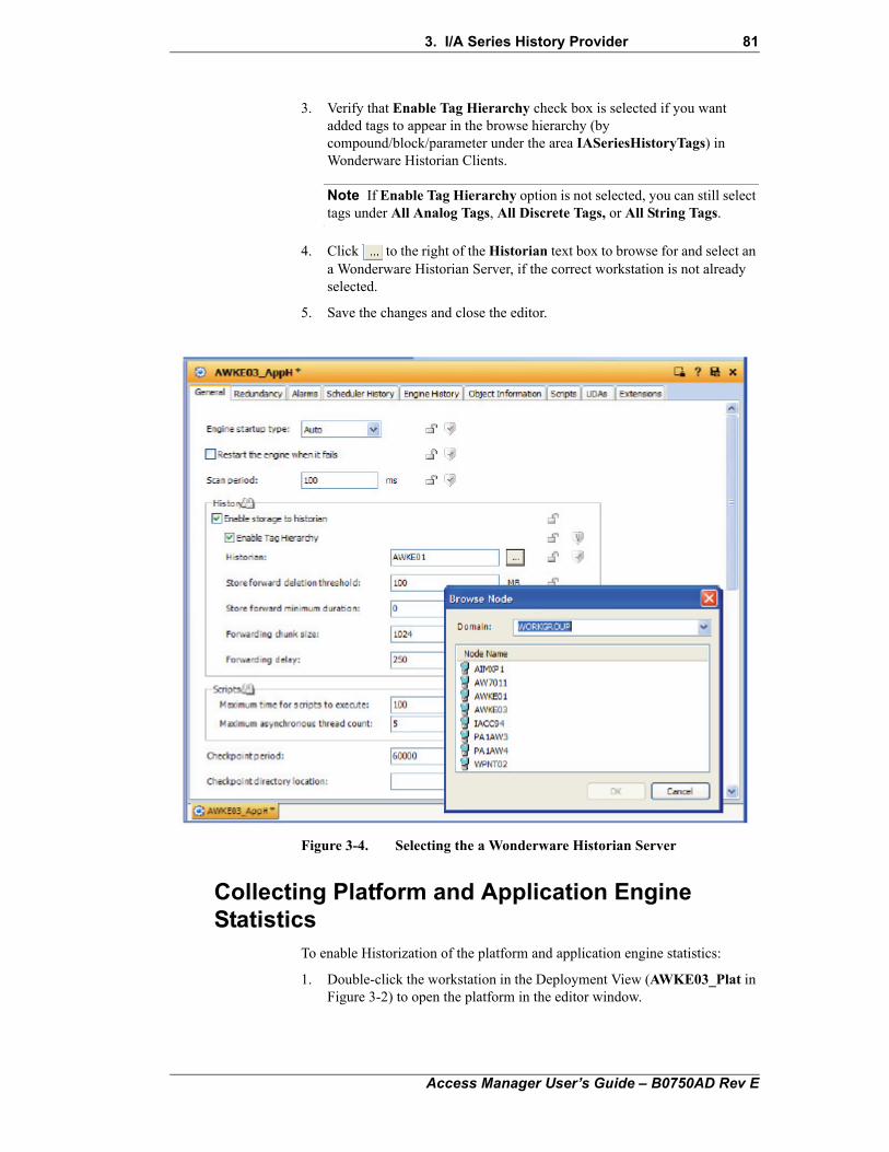
3. I/A Series History Provider 81
3. Verify that Enable Tag Hierarchy check box is selected if you want added tags to appear in the browse hierarchy (by compound/block/parameter under the area IASeriesHistoryTags) in Wonderware Historian Clients.
Note If Enable Tag Hierarchy option is not selected, you can still select tags under All Analog Tags, All Discrete Tags, or All String Tags.
4. Click to the right of the Historian text box to browse for and select an a Wonderware Historian Server, if the correct workstation is not already selected.
5. Save the changes and close the editor.
Figure 3-4. Selecting the a Wonderware Historian Server
Collecting Platform and Application Engine Statistics
To enable Historization of the platform and application engine statistics:
1. Double-click the workstation in the Deployment View (AWKE03_Plat in Figure 3-2) to open the platform in the editor window.
Access Manager User’s Guide – B0750AD Rev E
82 3. I/A Series History Provider
2. Click the Engine tab, and verify that Enable storage to historian check box is selected.
Enable Tag Hierarchy check box is automatically selected.
3. Select the Platform History, Scheduler History, and Engine History tabs in turn and configure the statistics of interest on each page.
4. Click icon to save the changes and close the editor.
5. Double-click the history application engine (AWKE03_AppH in Figure 3-2), click the Scheduler History and Engine History tabs in turn, and configure the statistics of interest on each page.
6. Click icon to save the changes and close the editor.
Redundant HistoryTo implement redundant history collection, if the history object is present on the backup workstation, it must be removed, and the primary workstation must be identified in the compounds from which the samples are to be collected.
The following steps provide an overview of setting up redundant collection. For detailed instructions, refer to Wonderware FactorySuite A2 Deployment Guide.
1. Select the backup workstation in the Deployment tab, if present; undeploy and delete the History App Engine, its Area, and History Object (that were created and deployed by the FCS install program), if present.
2. Enable redundancy using the Redundancy tab of the Primary App Engine.
Access Manager User’s Guide – B0750AD Rev E
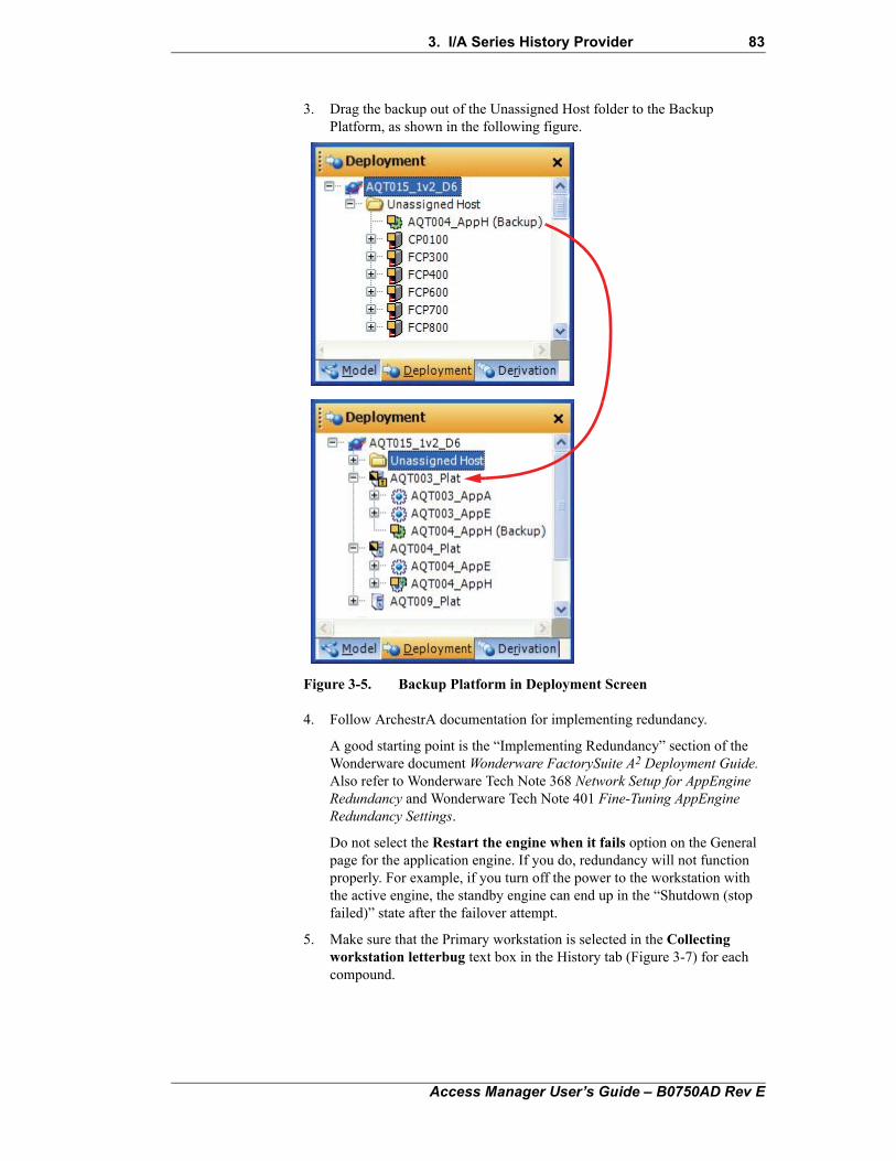
3. I/A Series History Provider 83
3. Drag the backup out of the Unassigned Host folder to the Backup Platform, as shown in the following figure.
Figure 3-5. Backup Platform in Deployment Screen
4. Follow ArchestrA documentation for implementing redundancy.
A good starting point is the “Implementing Redundancy” section of the Wonderware document Wonderware FactorySuite A2 Deployment Guide. Also refer to Wonderware Tech Note 368 Network Setup for AppEngine Redundancy and Wonderware Tech Note 401 Fine-Tuning AppEngine Redundancy Settings.
Do not select the Restart the engine when it fails option on the General page for the application engine. If you do, redundancy will not function properly. For example, if you turn off the power to the workstation with the active engine, the standby engine can end up in the “Shutdown (stop failed)” state after the failover attempt.
5. Make sure that the Primary workstation is selected in the Collecting workstation letterbug text box in the History tab (Figure 3-7) for each compound.
Access Manager User’s Guide – B0750AD Rev E

84 3. I/A Series History Provider
Configuring Historian ConnectionsSelection of the data points to be collected is accomplished during configuration of individual blocks and compounds. Figure 3-6 shows the History tab in the Block Configurator being used to select points in a PID block to be historized.
Figure 3-6. Historizing Parameters
The table at the top of the tab lists the currently selected parameters with their scan rate, dead band, and other collection attributes described in Table 3-2.
Table 3-2. History Collection Attributes
Attribute Description
Description This optional description of the point can be up to 512 characters long.
Engineering Units A text string with a maximum length of 32 characters that is used to identify the unit of measure.
Force Storage Period The interval, in milliseconds, at which the value must be stored even if it has not changed by at least the dead band. This timer is reset each time the value is stored. Set the attribute to 0 to disable forced storage. Set the attribute to a value between 0 and the scan rate to store the value with every scan.
Access Manager User’s Guide – B0750AD Rev E
3. I/A Series History Provider 85
Figure 3-7 shows a compound (CP_ALM) opened in the Block Configurator. The History tab is being used to designate the collecting workstation, in addition to specifying any compound parameters that are to be collected.
• Use the Collecting workstation letterbug drop-down list to select the workstation (and thus the I/A Series History Provider application object on that station) to collect samples from the compound.
When the block is deployed to the I/A Series system, the collection points are added to the history object specified in the containing compound.
Note If the application engine is redundant, make sure the primary workstation is selected, not the backup workstation.
The Deployed Collecting workstation letterbug box is read-only that shows the workstation selected when the compound was last deployed. The field is blank when the compound is undeployed.
Scan Rate The rate, in milliseconds, at which the I/A Series Object Manager will scan the point for collection.
Trend High, Trend Low Default maximum and minimum of the default value scale for trend clients.
Dead Band Minimum change in the value for the value to be stored. The value is not stored if the change since the last time the value was stored is less than the dead band. Set the attribute to 0 to store the value at every scan.
On Message, Off Message Custom message strings of up to 15 characters each for Boolean-type parameters. The default on and off messages are TRUE and FALSE, respectively.
Table 3-2. History Collection Attributes (Continued)
Attribute Description
Access Manager User’s Guide – B0750AD Rev E
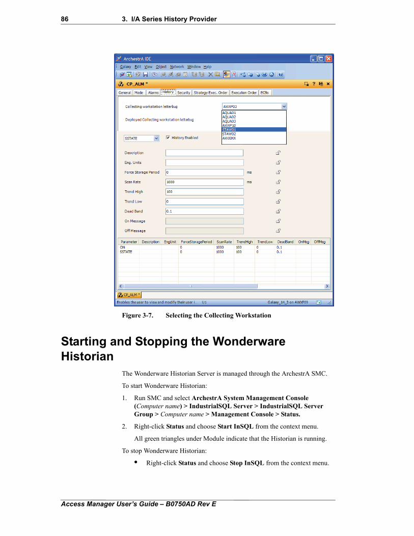
86 3. I/A Series History Provider
Figure 3-7. Selecting the Collecting Workstation
Starting and Stopping the Wonderware Historian
The Wonderware Historian Server is managed through the ArchestrA SMC.
To start Wonderware Historian:
1. Run SMC and select ArchestrA System Management Console (Computer name) > IndustrialSQL Server > IndustrialSQL Server Group > Computer name > Management Console > Status.
2. Right-click Status and choose Start InSQL from the context menu.
All green triangles under Module indicate that the Historian is running.
To stop Wonderware Historian:
• Right-click Status and choose Stop InSQL from the context menu.
Access Manager User’s Guide – B0750AD Rev E
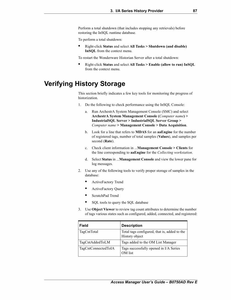
3. I/A Series History Provider 87
Perform a total shutdown (that includes stopping any retrievals) before restoring the InSQL runtime database.
To perform a total shutdown:
• Right-click Status and select All Tasks > Shutdown (and disable) InSQL from the context menu.
To restart the Wonderware Historian Server after a total shutdown:
• Right-click Status and select All Tasks > Enable (allow to run) InSQL from the context menu.
Verifying History StorageThis section briefly indicates a few key tools for monitoring the progress of historization.
1. Do the following to check performance using the InSQL Console:
a. Run ArchestrA System Management Console (SMC) and select ArchestrA System Management Console (Computer name) > IndustrialSQL Server > IndustrialSQL Server Group > Computer name > Management Console > Data Acquisition.
b. Look for a line that refers to MDAS for an aaEngine for the number of registered tags, number of total samples (Values), and samples per second (Rate).
c. Check client information in ...Management Console > Clients for the line corresponding to aaEngine for the Collecting workstation.
d. Select Status in ...Management Console and view the lower pane for log messages.
2. Use any of the following tools to verify proper storage of samples in the database:
• ActiveFactory Trend
• ActiveFactory Query
• ScratchPad Trend
• SQL tools to query the SQL database
3. Use Object Viewer to review tag count attributes to determine the number of tags various states such as configured, added, connected, and registered:
Field Description
TagCntTotal Total tags configured, that is, added to the History object
TagCntAddedToLM Tags added to the OM List Manager
TagCntConnectedToIA Tags successfully opened in I/A Series OM list
Access Manager User’s Guide – B0750AD Rev E
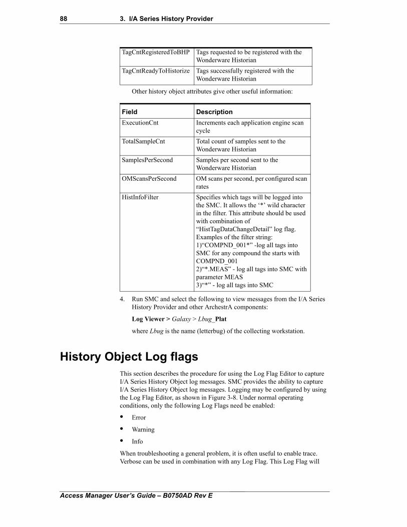
88 3. I/A Series History Provider
Other history object attributes give other useful information:
4. Run SMC and select the following to view messages from the I/A Series History Provider and other ArchestrA components:
Log Viewer > Galaxy > Lbug_Plat
where Lbug is the name (letterbug) of the collecting workstation.
History Object Log flagsThis section describes the procedure for using the Log Flag Editor to capture I/A Series History Object log messages. SMC provides the ability to capture I/A Series History Object log messages. Logging may be configured by using the Log Flag Editor, as shown in Figure 3-8. Under normal operating conditions, only the following Log Flags need be enabled:
• Error
• Warning
• Info
When troubleshooting a general problem, it is often useful to enable trace. Verbose can be used in combination with any Log Flag. This Log Flag will
TagCntRegisteredToBHP Tags requested to be registered with the Wonderware Historian
TagCntReadyToHistorize Tags successfully registered with the Wonderware Historian
Field Description
ExecutionCnt Increments each application engine scan cycle
TotalSampleCnt Total count of samples sent to the Wonderware Historian
SamplesPerSecond Samples per second sent to the Wonderware Historian
OMScansPerSecond OM scans per second, per configured scan rates
HistInfoFilter Specifies which tags will be logged into the SMC. It allows the ‘*’ wild character in the filter. This attribute should be used with combination of “HistTagDataChangeDetail” log flag.Examples of the filter string: 1)“COMPND_001*” -log all tags into SMC for any compound the starts with COMPND_001 2)“*.MEAS” - log all tags into SMC with parameter MEAS 3)“*” - log all tags into SMC
Access Manager User’s Guide – B0750AD Rev E
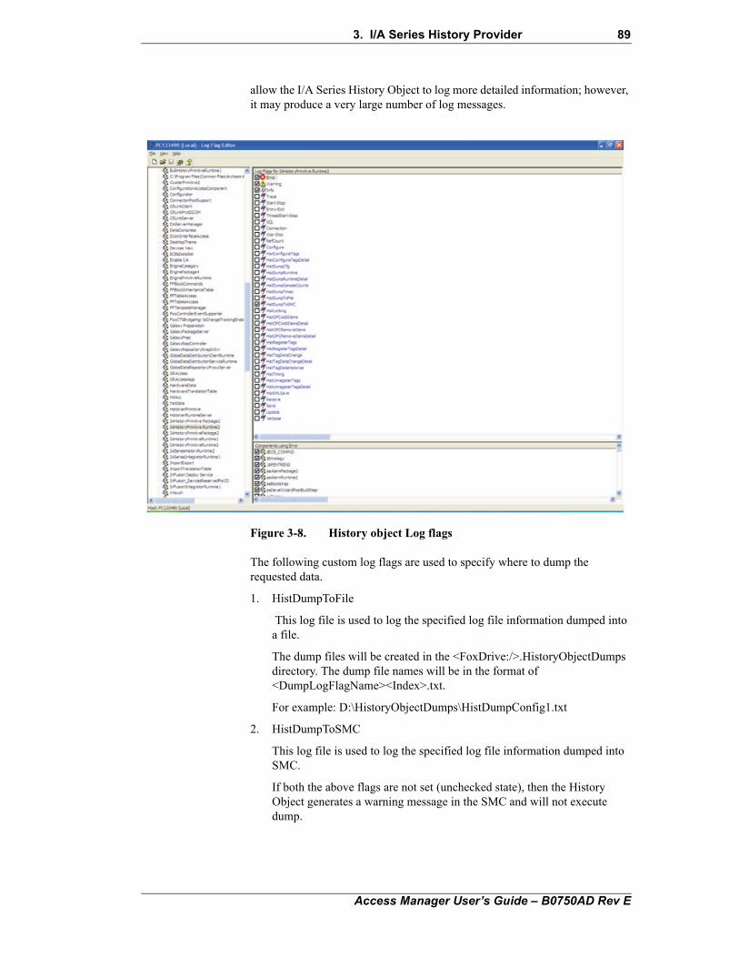
3. I/A Series History Provider 89
allow the I/A Series History Object to log more detailed information; however, it may produce a very large number of log messages.
Figure 3-8. History object Log flags
The following custom log flags are used to specify where to dump the requested data.
1. HistDumpToFile
This log file is used to log the specified log file information dumped into a file.
The dump files will be created in the <FoxDrive:/>.HistoryObjectDumps directory. The dump file names will be in the format of <DumpLogFlagName><Index>.txt.
For example: D:\HistoryObjectDumps\HistDumpConfig1.txt
2. HistDumpToSMC
This log file is used to log the specified log file information dumped into SMC.
If both the above flags are not set (unchecked state), then the History Object generates a warning message in the SMC and will not execute dump.
Access Manager User’s Guide – B0750AD Rev E

90 3. I/A Series History Provider
Access Manager User’s Guide – B0750AD Rev E
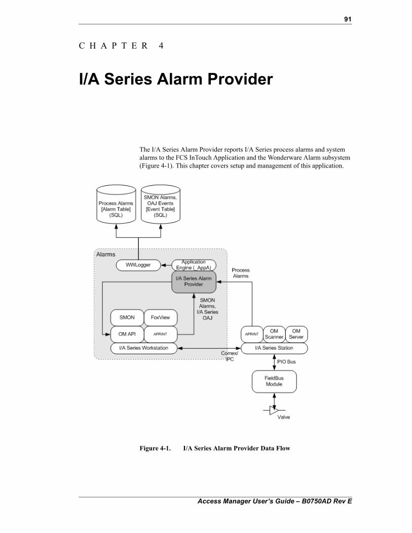
91
C H A P T E R 4
I/A Series Alarm Provider
The I/A Series Alarm Provider reports I/A Series process alarms and system alarms to the FCS InTouch Application and the Wonderware Alarm subsystem (Figure 4-1). This chapter covers setup and management of this application.
Figure 4-1. I/A Series Alarm Provider Data Flow
Access Manager User’s Guide – B0750AD Rev E
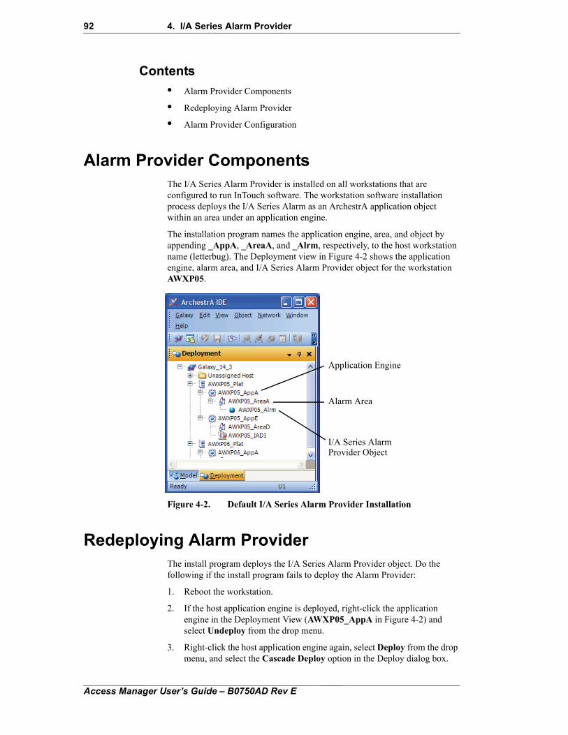
92 4. I/A Series Alarm Provider
Contents
• Alarm Provider Components
• Redeploying Alarm Provider
• Alarm Provider Configuration
Alarm Provider ComponentsThe I/A Series Alarm Provider is installed on all workstations that are configured to run InTouch software. The workstation software installation process deploys the I/A Series Alarm as an ArchestrA application object within an area under an application engine.
The installation program names the application engine, area, and object by appending _AppA, _AreaA, and _Alrm, respectively, to the host workstation name (letterbug). The Deployment view in Figure 4-2 shows the application engine, alarm area, and I/A Series Alarm Provider object for the workstation AWXP05.
Figure 4-2. Default I/A Series Alarm Provider Installation
Redeploying Alarm ProviderThe install program deploys the I/A Series Alarm Provider object. Do the following if the install program fails to deploy the Alarm Provider:
1. Reboot the workstation.
2. If the host application engine is deployed, right-click the application engine in the Deployment View (AWXP05_AppA in Figure 4-2) and select Undeploy from the drop menu.
3. Right-click the host application engine again, select Deploy from the drop menu, and select the Cascade Deploy option in the Deploy dialog box.
Application Engine
Alarm Area
I/A Series AlarmProvider Object
Access Manager User’s Guide – B0750AD Rev E
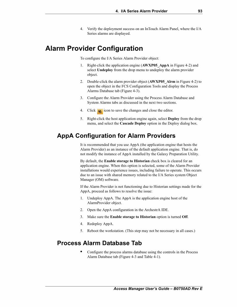
4. I/A Series Alarm Provider 93
4. Verify the deployment success on an InTouch Alarm Panel, where the I/A Series alarms are displayed.
Alarm Provider ConfigurationTo configure the I/A Series Alarm Provider object:
1. Right-click the application engine (AWXP05_AppA in Figure 4-2) and select Undeploy from the drop menu to undeploy the alarm provider object.
2. Double-click the alarm provider object (AWXP05_Alrm in Figure 4-2) to open the object in the FCS Configuration Tools and display the Process Alarms Database tab (Figure 4-3).
3. Configure the Alarm Provider using the Process Alarm Database and System Alarms tabs as discussed in the next two sections.
4. Click icon to save the changes and close the editor.
5. Right-click the host application engine again, select Deploy from the drop menu, and select the Cascade Deploy option in the Deploy dialog box.
AppA Configuration for Alarm ProvidersIt is recommended that you use AppA (the application engine that hosts the Alarm Provider) as an instance of the default application engine. That is, do not modify the instance of AppA installed by the Galaxy Preparation Utility.
By default, the Enable storage to Historian check box is cleared for an application engine. When this option is selected, some of the Alarm Provider installations would experience issues, including failure to operate. This occurs due to an issue with shared memory related to the I/A Series system Object Manager (OM) software.
If the Alarm Provider is not functioning due to Historian settings made for the AppA, proceed as follows to resolve the issue:
1. Undeploy AppA. The AppA is the application engine host of the AlarmProvider object.
2. Open the AppA configuration in the ArchestrA IDE.
3. Make sure the Enable storage to Historian option is turned Off.
4. Redeploy AppA.
5. Reboot the workstation. (This step may not be necessary in all cases.)
Process Alarm Database Tab• Configure the process alarms database using the controls in the Process
Alarm Database tab (Figure 4-3 and Table 4-1).
Access Manager User’s Guide – B0750AD Rev E
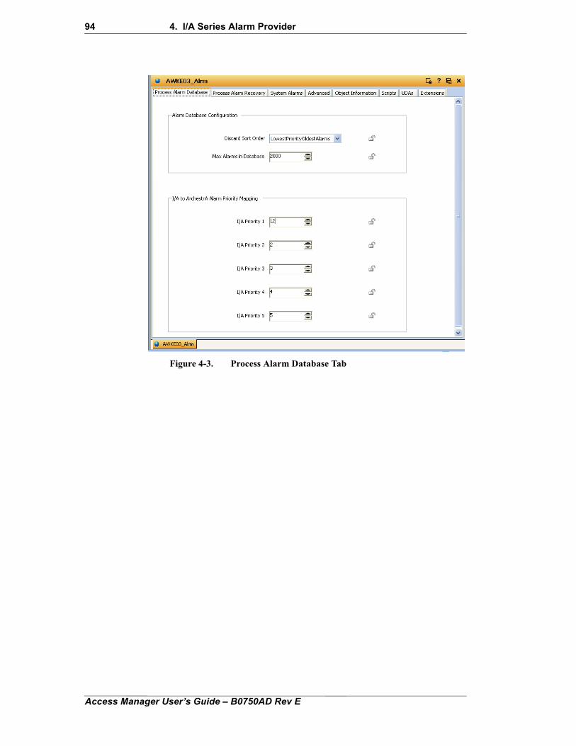
94 4. I/A Series Alarm Provider
Figure 4-3. Process Alarm Database TabAccess Manager User’s Guide – B0750AD Rev E
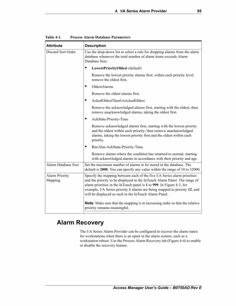
4. I/A Series Alarm Provider 95
Alarm RecoveryThe I/A Series Alarm Provider can be configured to recover the alarm states for workstations when there is an upset in the alarm system, such as a workstation reboot. Use the Process Alarm Recovery tab (Figure 4-4) to enable or disable the recovery feature.
Table 4-1. Process Alarm Database Parameters
Attribute Description
Discard Sort Order Use the drop-down list to select a rule for dropping alarms from the alarm database whenever the total number of alarm items exceeds Alarm Database Size:
• LowestPriorityOldest (default)
Remove the lowest priority alarms first; within each priority level, remove the oldest first.
• OldestAlarms
Remove the oldest alarms first.
• AckedOldestThenUnAckedOldest
Remove the acknowledged alarms first, starting with the oldest; then remove unacknowledged alarms, taking the oldest first.
• AckState-Priority-Time
Remove acknowledged alarms first, starting with the lowest priority and the oldest within each priority; then remove unacknowledged alarms, taking the lowest priority first and the oldest within each priority.
• Rtn/Alm-AckState-Priority-Time
Remove alarms where the condition has returned to normal, starting with acknowledged alarms in accordance with their priority and age.
Alarm Database Size Set the maximum number of alarms to be stored in the database. The default is 2000. You can specify any value within the range of 10 to 32000.
Alarm Priority Mapping
Specify the mapping between each of the five I/A Series alarm priorities and the priority to be displayed in the InTouch Alarm Panel. The range of alarm priorities in the InTouch panel is 1 to 999. In Figure 4-3, for example, I/A Series priority 1 alarms are being mapped to priority 12, and will be displayed as such in the InTouch Alarm Panel.
Note Make sure that the mapping is in increasing order so that the relative priority remains meaningful.
Access Manager User’s Guide – B0750AD Rev E
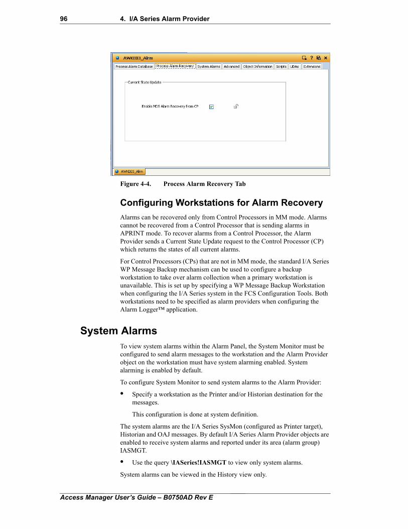
96 4. I/A Series Alarm Provider
Figure 4-4. Process Alarm Recovery Tab
Configuring Workstations for Alarm Recovery
Alarms can be recovered only from Control Processors in MM mode. Alarms cannot be recovered from a Control Processor that is sending alarms in APRINT mode. To recover alarms from a Control Processor, the Alarm Provider sends a Current State Update request to the Control Processor (CP) which returns the states of all current alarms.
For Control Processors (CPs) that are not in MM mode, the standard I/A Series WP Message Backup mechanism can be used to configure a backup workstation to take over alarm collection when a primary workstation is unavailable. This is set up by specifying a WP Message Backup Workstation when configuring the I/A Series system in the FCS Configuration Tools. Both workstations need to be specified as alarm providers when configuring the Alarm Logger™ application.
System AlarmsTo view system alarms within the Alarm Panel, the System Monitor must be configured to send alarm messages to the workstation and the Alarm Provider object on the workstation must have system alarming enabled. System alarming is enabled by default.
To configure System Monitor to send system alarms to the Alarm Provider:
• Specify a workstation as the Printer and/or Historian destination for the messages.
This configuration is done at system definition.
The system alarms are the I/A Series SysMon (configured as Printer target), Historian and OAJ messages. By default I/A Series Alarm Provider objects are enabled to receive system alarms and reported under its area (alarm group) IASMGT.
• Use the query \IASeries!IASMGT to view only system alarms.
System alarms can be viewed in the History view only.
Access Manager User’s Guide – B0750AD Rev E
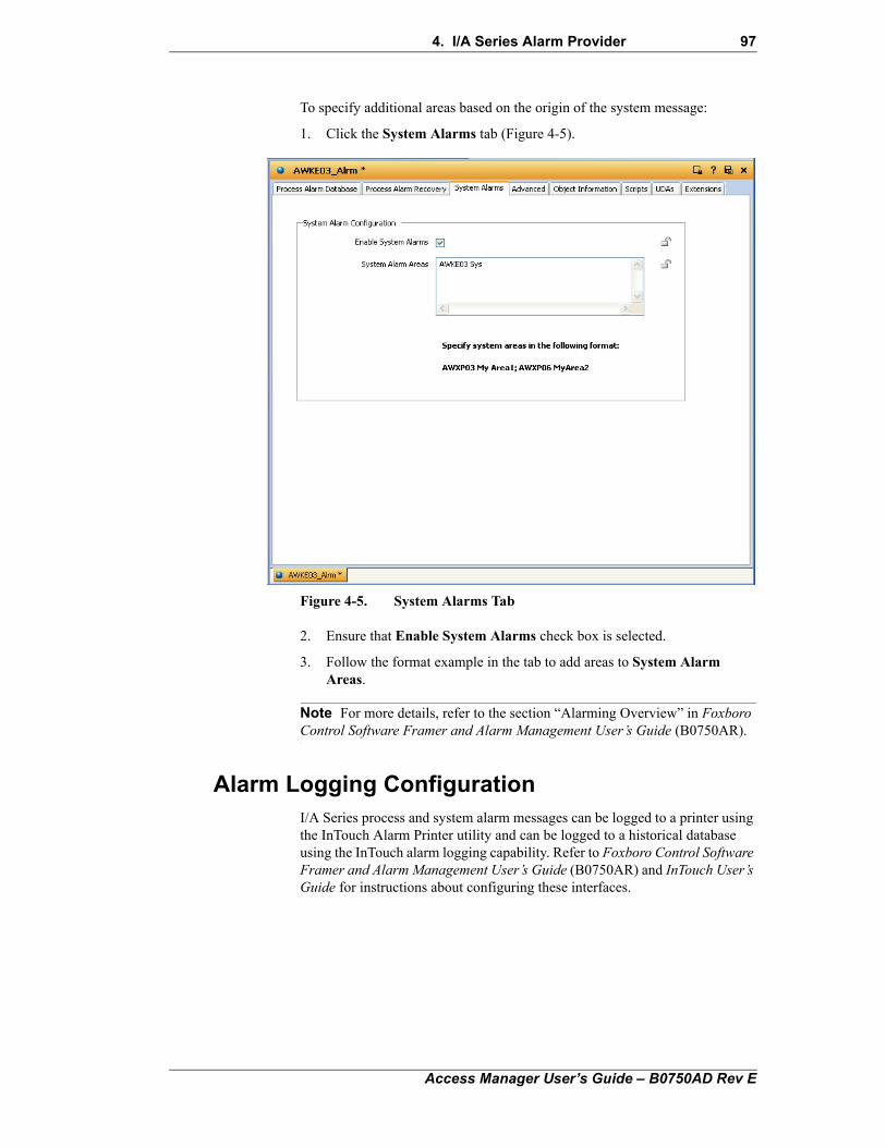
4. I/A Series Alarm Provider 97
To specify additional areas based on the origin of the system message:
1. Click the System Alarms tab (Figure 4-5).
Figure 4-5. System Alarms Tab
2. Ensure that Enable System Alarms check box is selected.
3. Follow the format example in the tab to add areas to System Alarm Areas.
Note For more details, refer to the section “Alarming Overview” in Foxboro Control Software Framer and Alarm Management User’s Guide (B0750AR).
Alarm Logging ConfigurationI/A Series process and system alarm messages can be logged to a printer using the InTouch Alarm Printer utility and can be logged to a historical database using the InTouch alarm logging capability. Refer to Foxboro Control Software Framer and Alarm Management User’s Guide (B0750AR) and InTouch User’s Guide for instructions about configuring these interfaces.
Access Manager User’s Guide – B0750AD Rev E

98 4. I/A Series Alarm Provider
Access Manager User’s Guide – B0750AD Rev E
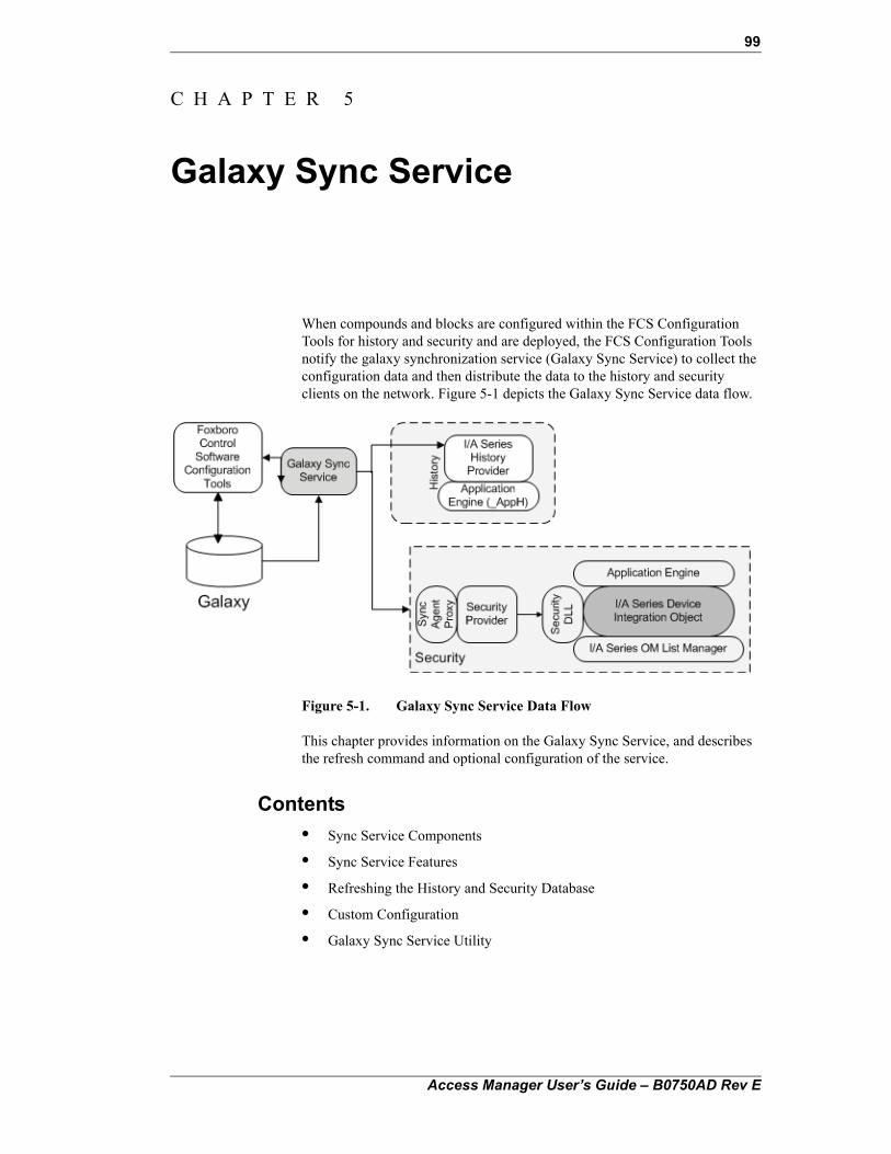
99
C H A P T E R 5
Galaxy Sync Service
When compounds and blocks are configured within the FCS Configuration Tools for history and security and are deployed, the FCS Configuration Tools notify the galaxy synchronization service (Galaxy Sync Service) to collect the configuration data and then distribute the data to the history and security clients on the network. Figure 5-1 depicts the Galaxy Sync Service data flow.
Figure 5-1. Galaxy Sync Service Data Flow
This chapter provides information on the Galaxy Sync Service, and describes the refresh command and optional configuration of the service.
Contents
• Sync Service Components
• Sync Service Features
• Refreshing the History and Security Database
• Custom Configuration
• Galaxy Sync Service Utility
Access Manager User’s Guide – B0750AD Rev E
100 5. Galaxy Sync Service
Sync Service Components The Galaxy Sync Service is installed on the galaxy repository server and set to start up automatically when the server boots up.
The client-side components SyncAgentCollector.dll, SyncAgentProxy.dll, and Invensys_InFusion_Access_SyncAgent_DataInterop.dll, and associated .dlls are installed on the clients where the I/A Series Security and/or I/A Series History Providers are deployed. These objects connect to the Galaxy Sync Service.
Sync Service FeaturesThe Galaxy Sync Service reads history and security configuration data from the galaxy when activated by the control database deployment package and creates XML files containing the data read from the galaxy:
GalaxySecurity1.xml ... GalaxySecurity20.xml
GalaxyHistory1.xml ... GalaxyHistory20.xml
These files are stored in the framework bin directory at:
\ProgramFiles\ArchestrA\Framework\Bin\Invensys\Access\SyncService
These files, which are cyclically overwritten each time a deployment occurs, may be viewed between deployment operations.
Additional features include:
• The Galaxy Sync Service is designed to handle multiple security and history clients. The SyncAgentProxy is used by client software to establish a connection with the Galaxy Sync Service (and automatically re-establish the connection if it is lost).
• The Galaxy Sync Service delivers all data configured for history and security to the appropriate workstations. In the case of security, it is the entire set of configured tags for the entire system. History data is delivered to the collecting workstation identified in each tag’s containing compound, as described in “Configuring Historian Connections” on page 84.
• The Galaxy Sync Service maintains all configuration data and client states inside a SQL server database (InFusionDeployedDb). This database and tables can be examined using SQL Query Analyzer or Enterprise Manager.
• The FCS Configuration Tools can instruct the Galaxy Sync Service to perform a full database reset, as discussed in the next section.
• The Galaxy Sync Service determines and distributes default and initial security data.
• The Galaxy Sync Service supports redundant history collection.
• The galaxy server name and TCP/IP port number used by the Galaxy Sync Service can be specified in an optional configuration file for clients.
Access Manager User’s Guide – B0750AD Rev E
5. Galaxy Sync Service 101
Refreshing the History and Security DatabaseThe Galaxy Sync Service maintains all configuration data and client states inside a SQL Server database. The FCS Configuration Tools can instruct the Galaxy Sync Service to perform a reset of the database. The Galaxy menu item Refresh History and Security Database forces the FCS Configuration Tools to refresh every deployed CP cascade, populates the galaxy with new history and security data, and activates the Galaxy Sync Service.
This process refreshes the galaxy repository and clears the Galaxy Sync Service database of modify, delete and duplicate add transactions, ensuring the Galaxy Sync Service has only the latest history and security information contained in the smallest possible transaction set. A refresh does not deploy or undeploy compounds and blocks, or otherwise affect the operation of the CPs.
Note The refresh process is NOT intended for casual use. Rather, it is designed for use after a system has been initially configured (that is, near the end of system commissioning) or substantially re-configured (that is during a shutdown or maintenance period). It may also be used after a catastrophic failure has occurred that caused a database corruption or other similar problem.
The refresh process has two stages, the first of which takes 5 to 15 minutes per CP. The time to complete the second stage is proportional to the number of history tags and non-default security settings. The history refresh rate between the Galaxy Sync Service and the I/A Series History Provider is approximately 18,000 tags per minute. The security refresh rate between the Galaxy Sync Service and the I/A Series Security Provider is approximately 60,000 tags per minute.
No FCS Configuration Tools deploy or undeploy actions may occur while the first stage of the refresh process is in progress. The second stage causes a gap in history collection if done on a running system, because points are not historized until the History application object receives the refreshed set of tags from the Galaxy Sync Service, adds them to the I/A OM List Manager (thus opening OM lists) and registers the tags in the designated Wonderware Historian Server. Security is retained with the old values that last deployed until refresh operation is completed.
To refresh history and security objects:
1. Open the galaxy in FCS Configuration Tools, preferably on the galaxy repository server, if it is not already open.
2. Make sure all objects are closed.
3. Select the galaxy node at the top of the Template Toolbox or one of the Application Views.
4. Choose Galaxy > Refresh History and Security Database from the main menu.
The refresh feature works for systems configured with the FCS Configuration Tools. It does not work for systems configured with other tools such as IACC.
Access Manager User’s Guide – B0750AD Rev E
102 5. Galaxy Sync Service
Custom ConfigurationThe Galaxy Sync Service, the SyncAgentProxy (used by the History and Security Providers) and the SyncAgentCollector (used by the FCS Configuration Tools) can be configured using configuration files. Use of these configuration files is optional. Each is explained in the following sections.
Default Security Classification ConfigurationThe default Security Classification for all parameters is operate. However, a different default can be specified if desired. This is done with an entry for the parameter name to the configuration file:
SecurityParameterDefaults.xml
If no custom or default parameter security exists, the initial configurable security value will be used. If it is not available, the "default operate" will be used by clients.
The file is located in:
\Program Files\ArchestrA\Framework\Bin\Invensys\Access\SyncService
Only parameter names and security defaults (Security Classifications) specified in this file are sent to clients. The format for this file is as follows:
ParameterDefaults>
<Compound Name="initcpd" SecurityDefault="Default" />
<Parameter Name="initparam" SecurityDefault="Operate" />
<Parameter Name="ALMLEV" SecurityDefault="Operate" />
<Parameter Name="CINHIB" SecurityDefault="Operate" />
<Parameter Name="DEFINE" SecurityDefault="Operate" />
</ParameterDefaults
In the example above the entry for “initcpd” compound configures initial Security Group. The entry for parameter “initparam” configures the parameter’s initial Security Classification.
Note This file is read when the Galaxy Sync Service starts. If the file is changed while the Galaxy Sync Service is running, the Galaxy Sync Service must be stopped and restarted, and then the database refreshed (see “Refreshing the History and Security Database” on page 101) for the changes to take effect.
The purpose of the default Security Classification is to reduce the amount of security data sent to all clients by the Galaxy Sync Service. If a particular parameter has a Security Classification that is equivalent to the default for that parameter name, the Galaxy Sync Service does not send the Security Classification for that particular parameter to the client. When the client is queried for tag Security Classification information, if it has the tag, it returns the Security Classification. However, if it does not have a particular tag (compound.parameter or compound:block.parameter) it returns the default Security Classification for the parameter portion of that tag.
Access Manager User’s Guide – B0750AD Rev E

5. Galaxy Sync Service 103
Galaxy Sync Service ConfigurationThe Galaxy Sync Service uses a standard .NET application configuration file named:
Invensys.InFusion.Access.SyncAgent.SyncService.exe.config.
This file is located at:
\Program Files\Invensys\InFusion\CommonComponents\SyncService
The following items may be specified in this file, as shown in the example file below and in Table 5-1.
<configuration><appSettings><add key=“SyncServerPort” value=“6523”/><add key=“SecurityMessageSize” value=“1000”/><add key=“HistoryMessageSize” value=“255”/><add key=“SecurityDefaultsEnable” value=“Enabled”/><add key=“MutexLockEnable” value=“Enabled”/> <add key=“BatchSize” value=“50000”/> </appSettings>
</configuration>
Sync Agent ConfigurationThe SyncAgentProxy and the SyncAgentCollector can be configured using the file:
SyncAgentProxyConfig.xml
The file is located within the directory:
Table 5-1. Sync Service Configuration File
Key Description
SyncServerPort The port to use for the ClientActivatedObjects other than the default port of 6523. If you change the port, you must change the default in the proxy configuration file (see below) as well to match.
SecurityMessageSize Defines how many tags are sent to Security objects per call to the ClientActivatedObject method GetData. Use this parameter for performance tuning and to throttle the size of messages traveling across the network.
HistoryMessageSize Defines how many tags are sent to History objects per call to the ClientActivatedObject method GetData. Use this parameter for performance tuning and to throttle the size of messages traveling across the network.
MutexLockEnable Enables or disables the mutex locking code used by the FCS Configuration Tools to control access to critical resources.
BatchSize Size of bulk inserts performed for security data.
Access Manager User’s Guide – B0750AD Rev E
104 5. Galaxy Sync Service
\Program Files\ArchestrA\Framework\Bin\Invensys\Access\SyncService
This optional file changes the default galaxy server name and the default TCP/IP port. Under typical circumstances, the default values are desired so this file is not needed. By default, the ArchestrA file platformMapping.xml provides the galaxy server name. The default TCP/IP port is 6523.
An example file is located at:
\Program Files\ArchestrA\Framework\Bin\Invensys\Access
To use this file, edit the GalaxyMachineName and/or the Port Value, save the file and then move it one directory down, to:
\Program Files\ArchestrA\Framework\Bin\Invensys\Access\SyncService
You must cascade redeploy the local platform and restart the FCS Configuration Tools for the changes to take effect. The format for the SyncAgentProxyConfig.xml file is as follows:
<Configuration><GalaxyMachineName Name=“GalaxyMachine” /><Port Value=“6523” />
</Configuration>
Note All I/A Series stations have a six-character workstation name (letterbug). The example file shown above will not work if used without changing the GalaxyMachineName.
Galaxy Sync Service UtilityThis section describes the Galaxy Sync Service Utility application. The Galaxy Sync Service Utility can be used to control and configure the Galaxy Sync Service. This application may be used from any FCS workstation or from the server itself.
The Galaxy Sync Service Utility has two sets of tab pages. These are the management tab set (composed of the Service and Initialization tab pages) and the configuration tab set (composed of the Security Db and History Db tab pages). The management tab set provides the ability to manage the Sync Service from any FCS client (local or remote). The configuration tab set provides the ability to change the History and Security configuration. The configuration tab set is only available when the Galaxy Sync Service Utility is run on the Galaxy server.
Stopping and Starting the Galaxy Sync ServiceTo start the Galaxy Sync Service Utility application, choose All Programs > Invensys > InFusion Access > GalaxySyncServiceUtility from the Windows Start button.
To quit the Galaxy Sync Service Utility application, click the “x” button in the upper right corner of the application. Quitting the utility will not stop the
Access Manager User’s Guide – B0750AD Rev E
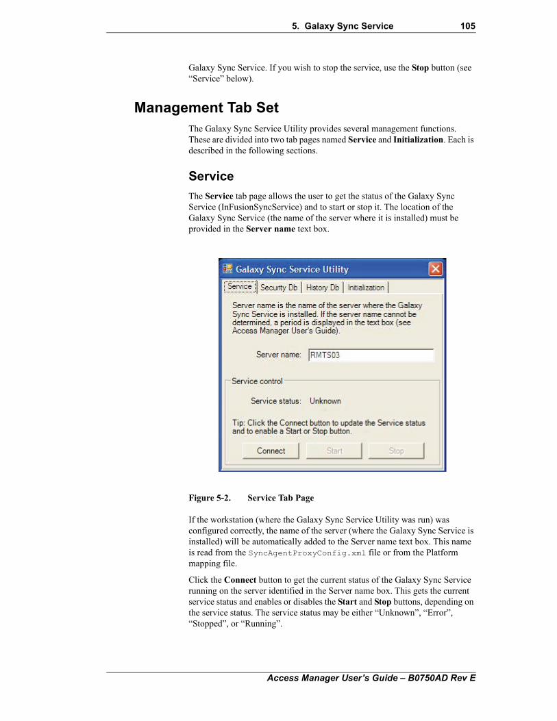
5. Galaxy Sync Service 105
Galaxy Sync Service. If you wish to stop the service, use the Stop button (see “Service” below).
Management Tab SetThe Galaxy Sync Service Utility provides several management functions. These are divided into two tab pages named Service and Initialization. Each is described in the following sections.
Service
The Service tab page allows the user to get the status of the Galaxy Sync Service (InFusionSyncService) and to start or stop it. The location of the Galaxy Sync Service (the name of the server where it is installed) must be provided in the Server name text box.
Figure 5-2. Service Tab Page
If the workstation (where the Galaxy Sync Service Utility was run) was configured correctly, the name of the server (where the Galaxy Sync Service is installed) will be automatically added to the Server name text box. This name is read from the SyncAgentProxyConfig.xml file or from the Platform mapping file.
Click the Connect button to get the current status of the Galaxy Sync Service running on the server identified in the Server name box. This gets the current service status and enables or disables the Start and Stop buttons, depending on the service status. The service status may be either “Unknown”, “Error”, “Stopped”, or “Running”.
Access Manager User’s Guide – B0750AD Rev E
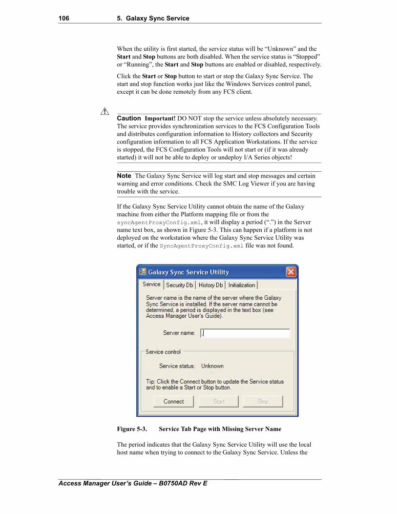
106 5. Galaxy Sync Service
!
When the utility is first started, the service status will be “Unknown” and the Start and Stop buttons are both disabled. When the service status is “Stopped” or “Running”, the Start and Stop buttons are enabled or disabled, respectively.
Click the Start or Stop button to start or stop the Galaxy Sync Service. The start and stop function works just like the Windows Services control panel, except it can be done remotely from any FCS client.
Caution Important! DO NOT stop the service unless absolutely necessary. The service provides synchronization services to the FCS Configuration Tools and distributes configuration information to History collectors and Security configuration information to all FCS Application Workstations. If the service is stopped, the FCS Configuration Tools will not start or (if it was already started) it will not be able to deploy or undeploy I/A Series objects!
Note The Galaxy Sync Service will log start and stop messages and certain warning and error conditions. Check the SMC Log Viewer if you are having trouble with the service.
If the Galaxy Sync Service Utility cannot obtain the name of the Galaxy machine from either the Platform mapping file or from the syncAgentProxyConfig.xml, it will display a period (“.”) in the Server name text box, as shown in Figure 5-3. This can happen if a platform is not deployed on the workstation where the Galaxy Sync Service Utility was started, or if the SyncAgentProxyConfig.xml file was not found.
Figure 5-3. Service Tab Page with Missing Server Name
The period indicates that the Galaxy Sync Service Utility will use the local host name when trying to connect to the Galaxy Sync Service. Unless the
Access Manager User’s Guide – B0750AD Rev E
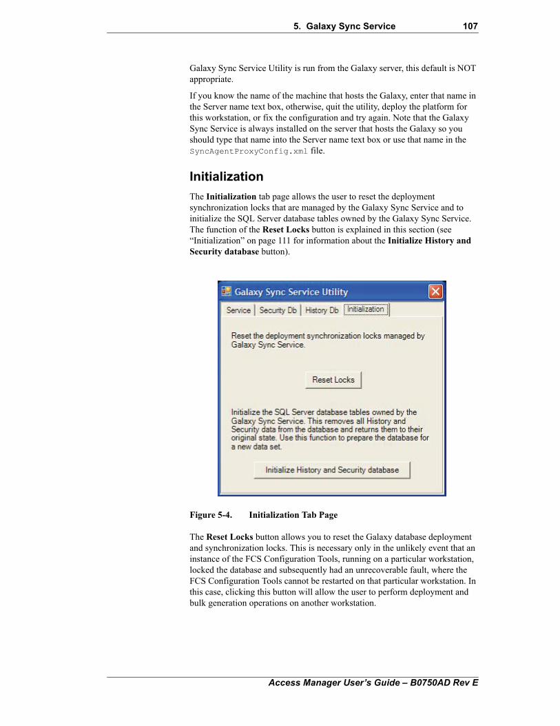
5. Galaxy Sync Service 107
Galaxy Sync Service Utility is run from the Galaxy server, this default is NOT appropriate.
If you know the name of the machine that hosts the Galaxy, enter that name in the Server name text box, otherwise, quit the utility, deploy the platform for this workstation, or fix the configuration and try again. Note that the Galaxy Sync Service is always installed on the server that hosts the Galaxy so you should type that name into the Server name text box or use that name in the SyncAgentProxyConfig.xml file.
Initialization
The Initialization tab page allows the user to reset the deployment synchronization locks that are managed by the Galaxy Sync Service and to initialize the SQL Server database tables owned by the Galaxy Sync Service. The function of the Reset Locks button is explained in this section (see “Initialization” on page 111 for information about the Initialize History and Security database button).
Figure 5-4. Initialization Tab Page
The Reset Locks button allows you to reset the Galaxy database deployment and synchronization locks. This is necessary only in the unlikely event that an instance of the FCS Configuration Tools, running on a particular workstation, locked the database and subsequently had an unrecoverable fault, where the FCS Configuration Tools cannot be restarted on that particular workstation. In this case, clicking this button will allow the user to perform deployment and bulk generation operations on another workstation.
Access Manager User’s Guide – B0750AD Rev E
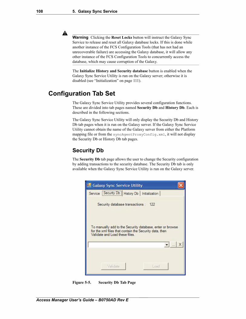
108 5. Galaxy Sync Service
!Warning Clicking the Reset Locks button will instruct the Galaxy Sync Service to release and reset all Galaxy database locks. If this is done while another instance of the FCS Configuration Tools (that has not had an unrecoverable failure) are accessing the Galaxy database, it will allow any other instance of the FCS Configuration Tools to concurrently access the database, which may cause corruption of the Galaxy.
The Initialize History and Security database button is enabled when the Galaxy Sync Service Utility is run on the Galaxy server; otherwise it is disabled (see “Initialization” on page 111).
Configuration Tab SetThe Galaxy Sync Service Utility provides several configuration functions. These are divided into tab pages named Security Db and History Db. Each is described in the following sections.
The Galaxy Sync Service Utility will only display the Security Db and History Db tab pages when it is run on the Galaxy server. If the Galaxy Sync Service Utility cannot obtain the name of the Galaxy server from either the Platform mapping file or from the syncAgentProxyConfig.xml, it will not display the Security Db or History Db tab pages.
Security Db
The Security Db tab page allows the user to change the Security configuration by adding transactions to the security database. The Security Db tab is only available when the Galaxy Sync Service Utility is run on the Galaxy server.
Figure 5-5. Security Db Tab Page
Access Manager User’s Guide – B0750AD Rev E
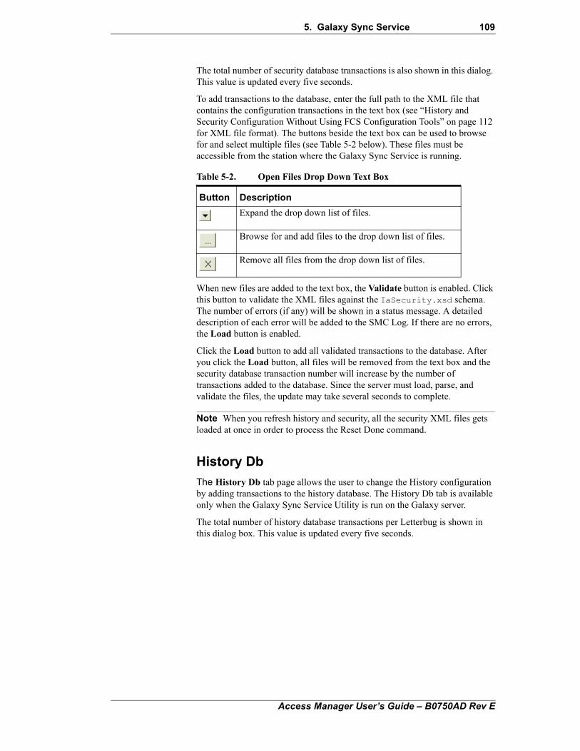
5. Galaxy Sync Service 109
The total number of security database transactions is also shown in this dialog. This value is updated every five seconds.
To add transactions to the database, enter the full path to the XML file that contains the configuration transactions in the text box (see “History and Security Configuration Without Using FCS Configuration Tools” on page 112 for XML file format). The buttons beside the text box can be used to browse for and select multiple files (see Table 5-2 below). These files must be accessible from the station where the Galaxy Sync Service is running.
When new files are added to the text box, the Validate button is enabled. Click this button to validate the XML files against the IaSecurity.xsd schema. The number of errors (if any) will be shown in a status message. A detailed description of each error will be added to the SMC Log. If there are no errors, the Load button is enabled.
Click the Load button to add all validated transactions to the database. After you click the Load button, all files will be removed from the text box and the security database transaction number will increase by the number of transactions added to the database. Since the server must load, parse, and validate the files, the update may take several seconds to complete.
Note When you refresh history and security, all the security XML files gets loaded at once in order to process the Reset Done command.
History Db
The History Db tab page allows the user to change the History configuration by adding transactions to the history database. The History Db tab is available only when the Galaxy Sync Service Utility is run on the Galaxy server.
The total number of history database transactions per Letterbug is shown in this dialog box. This value is updated every five seconds.
Table 5-2. Open Files Drop Down Text Box
Button Description
Expand the drop down list of files.
Browse for and add files to the drop down list of files.
Remove all files from the drop down list of files.
Access Manager User’s Guide – B0750AD Rev E
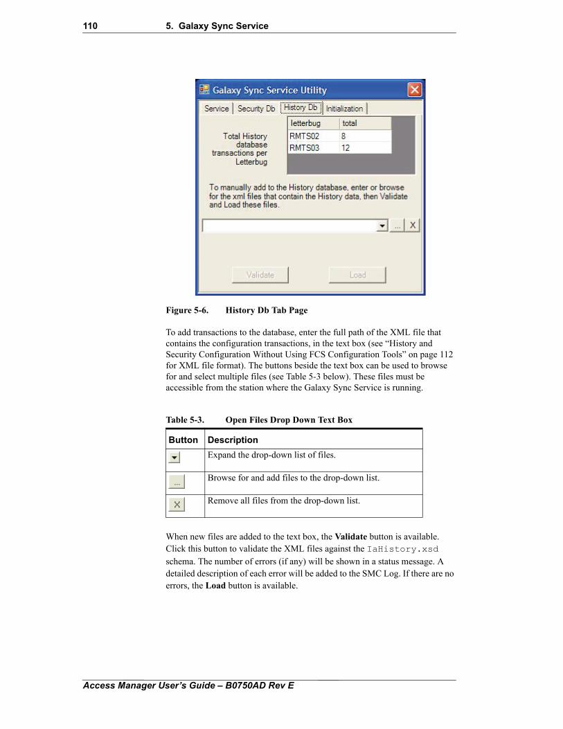
110 5. Galaxy Sync Service
Figure 5-6. History Db Tab Page
To add transactions to the database, enter the full path of the XML file that contains the configuration transactions, in the text box (see “History and Security Configuration Without Using FCS Configuration Tools” on page 112 for XML file format). The buttons beside the text box can be used to browse for and select multiple files (see Table 5-3 below). These files must be accessible from the station where the Galaxy Sync Service is running.
When new files are added to the text box, the Validate button is available. Click this button to validate the XML files against the IaHistory.xsd
schema. The number of errors (if any) will be shown in a status message. A detailed description of each error will be added to the SMC Log. If there are no errors, the Load button is available.
Table 5-3. Open Files Drop Down Text Box
Button Description
Expand the drop-down list of files.
Browse for and add files to the drop-down list.
Remove all files from the drop-down list.
Access Manager User’s Guide – B0750AD Rev E
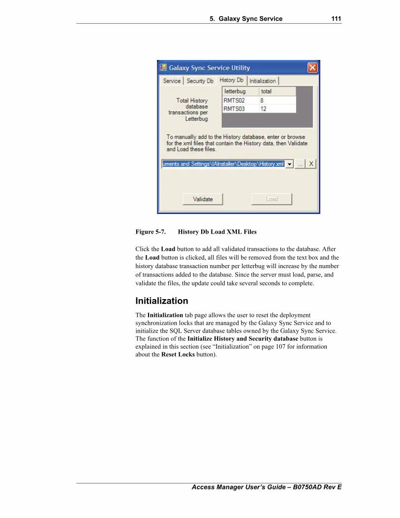
5. Galaxy Sync Service 111
Figure 5-7. History Db Load XML Files
Click the Load button to add all validated transactions to the database. After the Load button is clicked, all files will be removed from the text box and the history database transaction number per letterbug will increase by the number of transactions added to the database. Since the server must load, parse, and validate the files, the update could take several seconds to complete.
Initialization
The Initialization tab page allows the user to reset the deployment synchronization locks that are managed by the Galaxy Sync Service and to initialize the SQL Server database tables owned by the Galaxy Sync Service. The function of the Initialize History and Security database button is explained in this section (see “Initialization” on page 107 for information about the Reset Locks button).
Access Manager User’s Guide – B0750AD Rev E
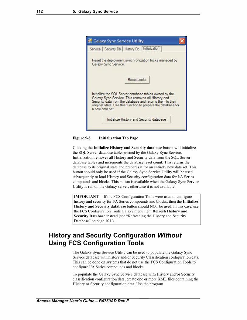
112 5. Galaxy Sync Service
Figure 5-8. Initialization Tab Page
Clicking the Initialize History and Security database button will initialize the SQL Server database tables owned by the Galaxy Sync Service. Initialization removes all History and Security data from the SQL Server database tables and increments the database reset count. This returns the database to its original state and prepares it for an entirely new data set. This button should only be used if the Galaxy Sync Service Utility will be used subsequently to load History and Security configuration data for I/A Series compounds and blocks. This button is available when the Galaxy Sync Service Utility is run on the Galaxy server; otherwise it is not available.
History and Security Configuration Without Using FCS Configuration Tools
The Galaxy Sync Service Utility can be used to populate the Galaxy Sync Service database with history and/or Security Classification configuration data. This can be done on systems that do not use the FCS Configuration Tools to configure I/A Series compounds and blocks.
To populate the Galaxy Sync Service database with History and/or Security classification configuration data, create one or more XML files containing the History or Security configuration data. Use the program
IMPORTANT If the FCS Configuration Tools were used to configure history and security for I/A Series compounds and blocks, then the Initialize History and Security database button should NOT be used. In this case, use the FCS Configuration Tools Galaxy menu item Refresh History and Security Database instead (see “Refreshing the History and Security Database” on page 101.).
Access Manager User’s Guide – B0750AD Rev E
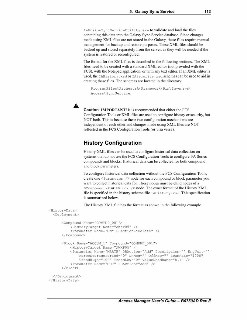
5. Galaxy Sync Service 113
!
InFusionSyncServiceUtility.exe to validate and load the files containing this data into the Galaxy Sync Service database. Since changes made using XML files are not stored in the Galaxy, these files require manual management for backup and restore purposes. These XML files should be backed up and stored separately from the server, as they will be needed if the system is restored or reconfigured.
The format for the XML files is described in the following sections. The XML files need to be created with a standard XML editor (not provided with the FCS), with the Notepad application, or with any text editor. If an XML editor is used, the IAHistory.xsd or IASecurity.xsd schemas can be used to aid in creating these files. The schemas are located in the directory:
ProgramFiles\ArchestrA\Framework\Bin\Invensys\Access\SyncService.
Caution IMPORTANT! It is recommended that either the FCS Configuration Tools or XML files are used to configure history or security, but NOT both. This is because these two configuration mechanisms are independent of each other and changes made using XML files are NOT reflected in the FCS Configuration Tools (or visa versa).
History Configuration
History XML files can be used to configure historical data collection on systems that do not use the FCS Configuration Tools to configure I/A Series compounds and blocks. Historical data can be collected for both compound and block parameters.
To configure historical data collection without the FCS Configuration Tools, create one <Parameter /> node for each compound or block parameter you want to collect historical data for. These nodes must be child nodes of a <Compound /> or <Block /> node. The exact format of the History XML file is specified in the history schema file IAHistory.xsd. This specification is summarized below.
The History XML file has the format as shown in the following example. <HistoryData><Deployment>
<Compound Name="COMPND_001"><HistoryTarget Name="AWXP05" /><Parameter Name="ON" DBAction="Delete" />
</Compound>
<Block Name="ACCUM_1" Compound="COMPND_001"><HistoryTarget Name="AWXP05" /><Parameter Name="MRATE" DBAction="Add" Description="" EngUnit=""
ForceStoragePeriod="0" OnMsg="" OffMsg="" ScanRate="1000" TrendHigh="100" TrendLow="0" ValueDeadBand="0.1" />
<Parameter Name="OUT" DBAction="Add" /></Block>
</Deployment></HistoryData>
Access Manager User’s Guide – B0750AD Rev E
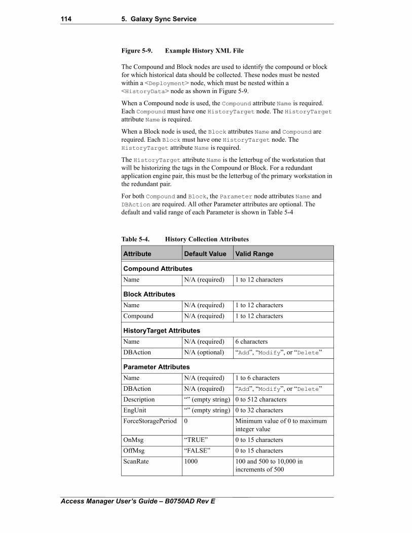
114 5. Galaxy Sync Service
Figure 5-9. Example History XML File
The Compound and Block nodes are used to identify the compound or block for which historical data should be collected. These nodes must be nested within a <Deployment> node, which must be nested within a <HistoryData> node as shown in Figure 5-9.
When a Compound node is used, the Compound attribute Name is required. Each Compound must have one HistoryTarget node. The HistoryTarget attribute Name is required.
When a Block node is used, the Block attributes Name and Compound are required. Each Block must have one HistoryTarget node. The HistoryTarget attribute Name is required.
The HistoryTarget attribute Name is the letterbug of the workstation that will be historizing the tags in the Compound or Block. For a redundant application engine pair, this must be the letterbug of the primary workstation in the redundant pair.
For both Compound and Block, the Parameter node attributes Name and DBAction are required. All other Parameter attributes are optional. The default and valid range of each Parameter is shown in Table 5-4
Table 5-4. History Collection Attributes
Attribute Default Value Valid Range
Compound Attributes
Name N/A (required) 1 to 12 characters
Block Attributes
Name N/A (required) 1 to 12 characters
Compound N/A (required) 1 to 12 characters
HistoryTarget Attributes
Name N/A (required) 6 characters
DBAction N/A (optional) “Add”, “Modify”, or “Delete”
Parameter Attributes
Name N/A (required) 1 to 6 characters
DBAction N/A (required) “Add”, “Modify”, or “Delete”
Description “” (empty string) 0 to 512 characters
EngUnit “” (empty string) 0 to 32 characters
ForceStoragePeriod 0 Minimum value of 0 to maximum integer value
OnMsg “TRUE” 0 to 15 characters
OffMsg “FALSE” 0 to 15 characters
ScanRate 1000 100 and 500 to 10,000 in increments of 500
Access Manager User’s Guide – B0750AD Rev E
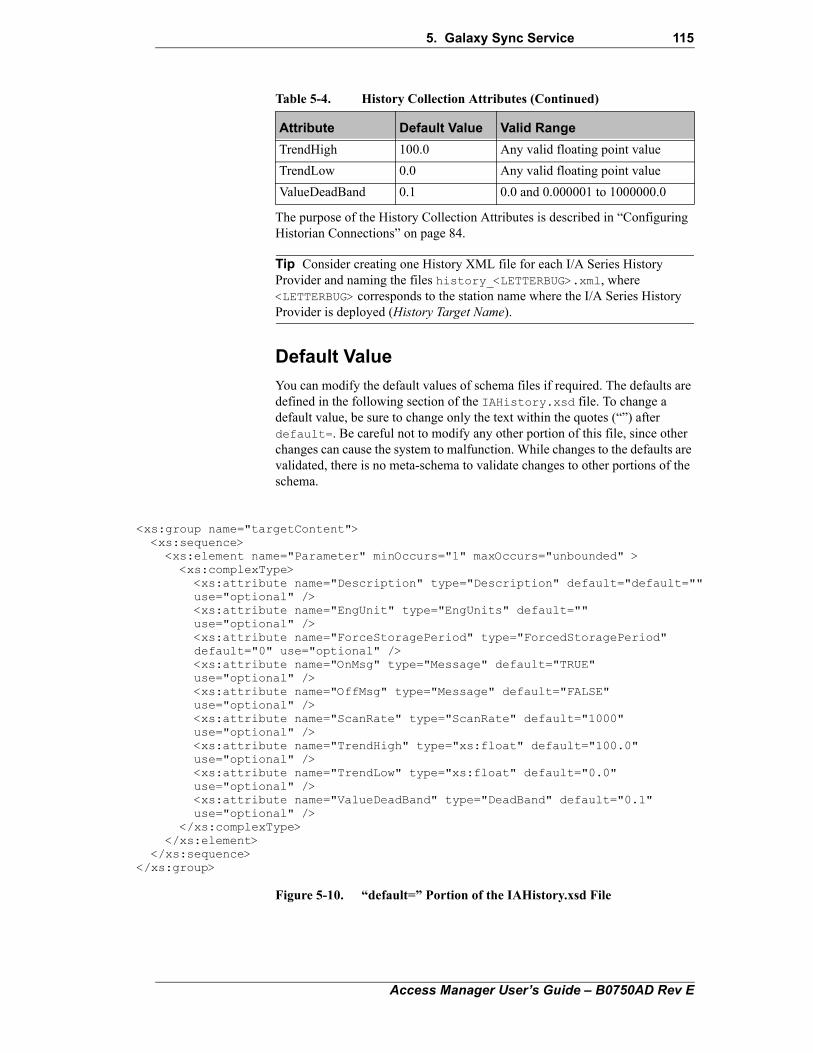
5. Galaxy Sync Service 115
<
<
The purpose of the History Collection Attributes is described in “Configuring Historian Connections” on page 84.
Tip Consider creating one History XML file for each I/A Series History Provider and naming the files history_<LETTERBUG>.xml, where <LETTERBUG> corresponds to the station name where the I/A Series History Provider is deployed (History Target Name).
Default Value
You can modify the default values of schema files if required. The defaults are defined in the following section of the IAHistory.xsd file. To change a default value, be sure to change only the text within the quotes (“”) after default=. Be careful not to modify any other portion of this file, since other changes can cause the system to malfunction. While changes to the defaults are validated, there is no meta-schema to validate changes to other portions of the schema.
Figure 5-10. “default=” Portion of the IAHistory.xsd File
TrendHigh 100.0 Any valid floating point value
TrendLow 0.0 Any valid floating point value
ValueDeadBand 0.1 0.0 and 0.000001 to 1000000.0
Table 5-4. History Collection Attributes (Continued)
Attribute Default Value Valid Range
xs:group name="targetContent"><xs:sequence>
<xs:element name="Parameter" minOccurs="1" maxOccurs="unbounded" ><xs:complexType><xs:attribute name="Description" type="Description" default="default=""use="optional" /><xs:attribute name="EngUnit" type="EngUnits" default="" use="optional" /><xs:attribute name="ForceStoragePeriod" type="ForcedStoragePeriod"default="0" use="optional" /><xs:attribute name="OnMsg" type="Message" default="TRUE"use="optional" /><xs:attribute name="OffMsg" type="Message" default="FALSE"use="optional" /><xs:attribute name="ScanRate" type="ScanRate" default="1000"use="optional" /><xs:attribute name="TrendHigh" type="xs:float" default="100.0"use="optional" /><xs:attribute name="TrendLow" type="xs:float" default="0.0"use="optional" /><xs:attribute name="ValueDeadBand" type="DeadBand" default="0.1"use="optional" />
</xs:complexType></xs:element>
</xs:sequence>/xs:group>
Access Manager User’s Guide – B0750AD Rev E
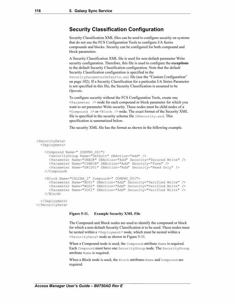
116 5. Galaxy Sync Service
Security Classification Configuration
Security Classification XML files can be used to configure security on systems that do not use the FCS Configuration Tools to configure I/A Series compounds and blocks. Security can be configured for both compound and block parameters.
A Security Classification XML file is used for non-default parameter Write security configuration. Therefore, this file is used to configure the exceptions to the default Security Classification configuration. Note that the default Security Classification configuration is specified in the SecurityParameterDefaults.xml file (see the “Custom Configuration” on page 102). If a Security Classification for a particular I/A Series Parameter is not specified in this file, the Security Classification is assumed to be Operate.
To configure security without the FCS Configuration Tools, create one <Parameter /> node for each compound or block parameter for which you want to set parameter Write security. These nodes must be child nodes of a <Compound /> or <Block /> node. The exact format of the Security XML file is specified in the security schema file IASecurity.xsd. This specification is summarized below.
The security XML file has the format as shown in the following example.
Figure 5-11. Example Security XML File
The Compound and Block nodes are used to identify the compound or block for which a non-default Security Classification is to be used. These nodes must be nested within a <Deployment> node, which must be nested within a <SecurityData> node as shown in Figure 5-11.
When a Compound node is used, the Compound attribute Name is required. Each Compound must have one SecurityGroup node. The SecurityGroup attribute Name is required.
When a Block node is used, the Block attributes Name and Compound are required.
<SecurityData> <Deployment>
<Compound Name=" COMPND_001"> <SecurityGroup Name="Default" DBAction="Add" /> <Parameter Name="UNACK" DBAction="Add" Security="Secured Write" /> <Parameter Name="CINHIB" DBAction="Add" Security="Tune" /> <Parameter Name="GR1DV1" DBAction="Add" Security="Read Only" /> </Compound>
<Block Name="CALCAH_1" Compound=" COMPND_001"> <Parameter Name="BO01" DBAction="Add" Security="Verified Write" /> <Parameter Name="BO02" DBAction="Add" Security="Verified Write" /> <Parameter Name="IO01" DBAction="Add" Security="Verified Write" /> </Block>
</Deployment></SecurityData>
Access Manager User’s Guide – B0750AD Rev E
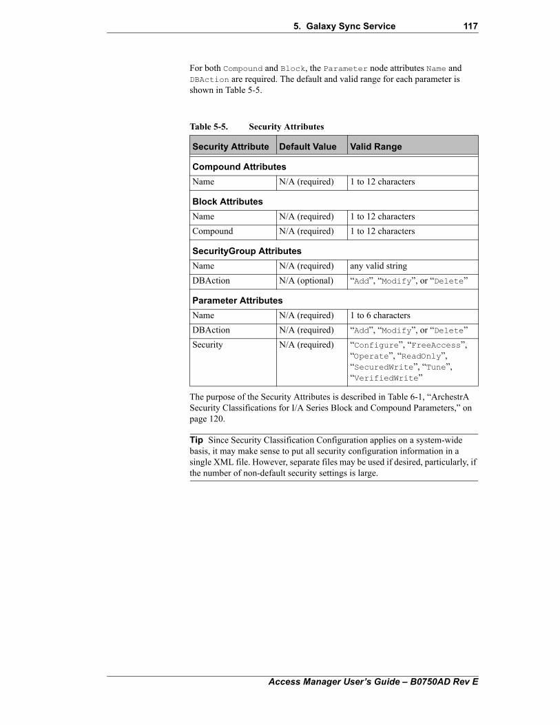
5. Galaxy Sync Service 117
For both Compound and Block, the Parameter node attributes Name and DBAction are required. The default and valid range for each parameter is shown in Table 5-5.
The purpose of the Security Attributes is described in Table 6-1, “ArchestrA Security Classifications for I/A Series Block and Compound Parameters,” on page 120.
Tip Since Security Classification Configuration applies on a system-wide basis, it may make sense to put all security configuration information in a single XML file. However, separate files may be used if desired, particularly, if the number of non-default security settings is large.
Table 5-5. Security Attributes
Security Attribute Default Value Valid Range
Compound Attributes
Name N/A (required) 1 to 12 characters
Block Attributes
Name N/A (required) 1 to 12 characters
Compound N/A (required) 1 to 12 characters
SecurityGroup Attributes
Name N/A (required) any valid string
DBAction N/A (optional) “Add”, “Modify”, or “Delete”
Parameter Attributes
Name N/A (required) 1 to 6 characters
DBAction N/A (required) “Add”, “Modify”, or “Delete”
Security N/A (required) “Configure”, “FreeAccess”, “Operate”, “ReadOnly”, “SecuredWrite”, “Tune”, “VerifiedWrite”
Access Manager User’s Guide – B0750AD Rev E

118 5. Galaxy Sync Service
Access Manager User’s Guide – B0750AD Rev E
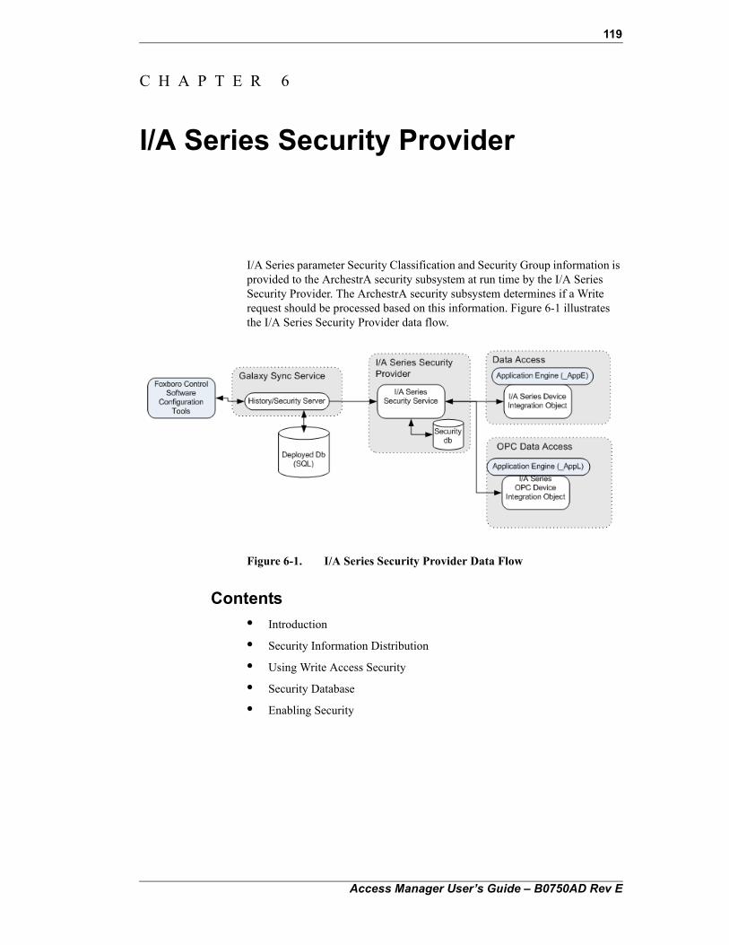
119
C H A P T E R 6
I/A Series Security Provider
I/A Series parameter Security Classification and Security Group information is provided to the ArchestrA security subsystem at run time by the I/A Series Security Provider. The ArchestrA security subsystem determines if a Write request should be processed based on this information. Figure 6-1 illustrates the I/A Series Security Provider data flow.
Figure 6-1. I/A Series Security Provider Data Flow
Contents
• Introduction
• Security Information Distribution
• Using Write Access Security
• Security Database
• Enabling Security
Access Manager User’s Guide – B0750AD Rev E
120 6. I/A Series Security Provider
IntroductionEach I/A Series block parameter and compound parameter has one of the following ArchestrA Security Classifications:
Each parameter is also associated with a Security Group, as defined by the user in the IDE or by using DirectAccess.
Note I/A Series shared variables are not configured in the FCS Configuration Tools. Tags of this type always have the Free Access Security Classification and are members of the Default Security Group.
The I/A Series Security Provider is a Windows server running on every I/A Series station.
Note While on scan, the Configure Security Classification functions like the Read Only Security Classification. This means that any tag with the Configure classification is always read-only when accessed through the I/A Series Device Integration Object.
Security Information DistributionThe security information used by the I/A Series Security Provider is generated by the FCS Configuration Tools during deployment. When I/A Series compounds and blocks are deployed, the FCS Configuration Tools write the security information related to the deployed objects into the DeployDB (InFusionDeployDB) database. The Galaxy Sync Service distributes the security information from the DeployDB database to all I/A Series workstations and I/A Series servers. On every I/A Series box the security
Table 6-1. ArchestrA Security Classifications for I/A Series Block and Compound Parameters
Security Classifications Description
Free Access Any user can write to these attributes. Requires no privileges.
Operate Operators can write to these attributes during normal day-to-day operations. This the default setting.
Tune Engineers involved in a tuning activity can write to these attributes.
Configure Writing to these attributes involves a significant configuration change, requiring the object to be off scan.
Secured Write Operators can write to these attributes with a forced re-authentication.
Verified Write Operators can write to these attributes. Similar to Secured Write, except that a second user authorization is also required.
Read Only Attributes are never written in the I/A Series system environment.
Access Manager User’s Guide – B0750AD Rev E
6. I/A Series Security Provider 121
information is stored locally in SecurityCache SQL Express database. The I/A Series Security Provider retrieves security information from the local SecurityCache database on client's request.
Using Write Access SecurityTo make use of parameter-based Write access security, I/A Series tags must be accessed through the I/A Series Device Integration Object. This means that the tag name must include the name of the I/A Series Device Integration Object (AWKE05_IADI, for example) in its full name or any other of the legal variations, including galaxy, scan group and/or extensions, as described in Chapter 2, "I/A Series Device Integration Objects".
When a Write occurs to a tag configured in this way, a security information request is sent to the I/A Series Device Integration Object from the ArchestrA security subsystem. The ArchestrA security subsystem compares the user credentials against the tag’s Security Classification and group. If the user has the proper security credentials for the tag, the Write request is sent to the I/A Series Device Integration Object, otherwise it is rejected at the requesting application. Useful information on the progress of the Write request is logged to the SMC.
Note I/A Series shared variables are not configured in the FCS Configuration Tools. Tags of this type always have the Free Access Security Classification and are members of the Default Security Group.
Security Database The local security database is a Microsoft SQL Express database containing custom and default Security Classifications for parameters and compounds. Additionally, the user can configure system-wide initial security in the default security parameter XML file and those values for default parameter and default Group are also stored in the local database. See the Chapter 5, “Galaxy Sync Service” for more information on the SecurityParameterDefaults.xml file.
This security database is built during the installation of FCS.
Enabling SecurityTo use the I/A Series Security Provider, you must first enable Galaxy Authentication mode in the FCS Configuration Tools.
To enable security:
1. Select the galaxy node at the top of the Template Toolbox and select Galaxy > Configure > Security from the main menu to open the Configure Security dialog box (Figure 6-2).
Access Manager User’s Guide – B0750AD Rev E
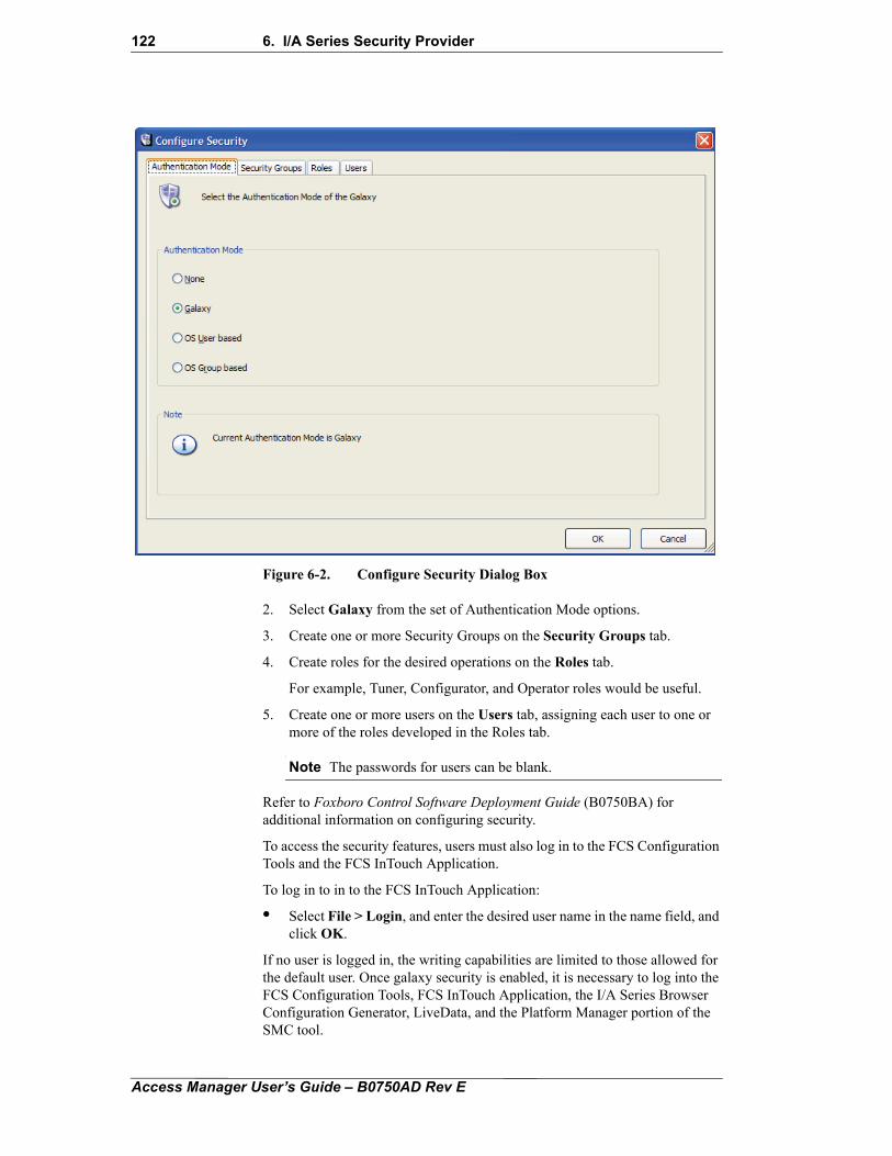
122 6. I/A Series Security Provider
Figure 6-2. Configure Security Dialog Box
2. Select Galaxy from the set of Authentication Mode options.
3. Create one or more Security Groups on the Security Groups tab.
4. Create roles for the desired operations on the Roles tab.
For example, Tuner, Configurator, and Operator roles would be useful.
5. Create one or more users on the Users tab, assigning each user to one or more of the roles developed in the Roles tab.
Note The passwords for users can be blank.
Refer to Foxboro Control Software Deployment Guide (B0750BA) for additional information on configuring security.
To access the security features, users must also log in to the FCS Configuration Tools and the FCS InTouch Application.
To log in to in to the FCS InTouch Application:
• Select File > Login, and enter the desired user name in the name field, and click OK.
If no user is logged in, the writing capabilities are limited to those allowed for the default user. Once galaxy security is enabled, it is necessary to log into the FCS Configuration Tools, FCS InTouch Application, the I/A Series Browser Configuration Generator, LiveData, and the Platform Manager portion of the SMC tool.
Access Manager User’s Guide – B0750AD Rev E
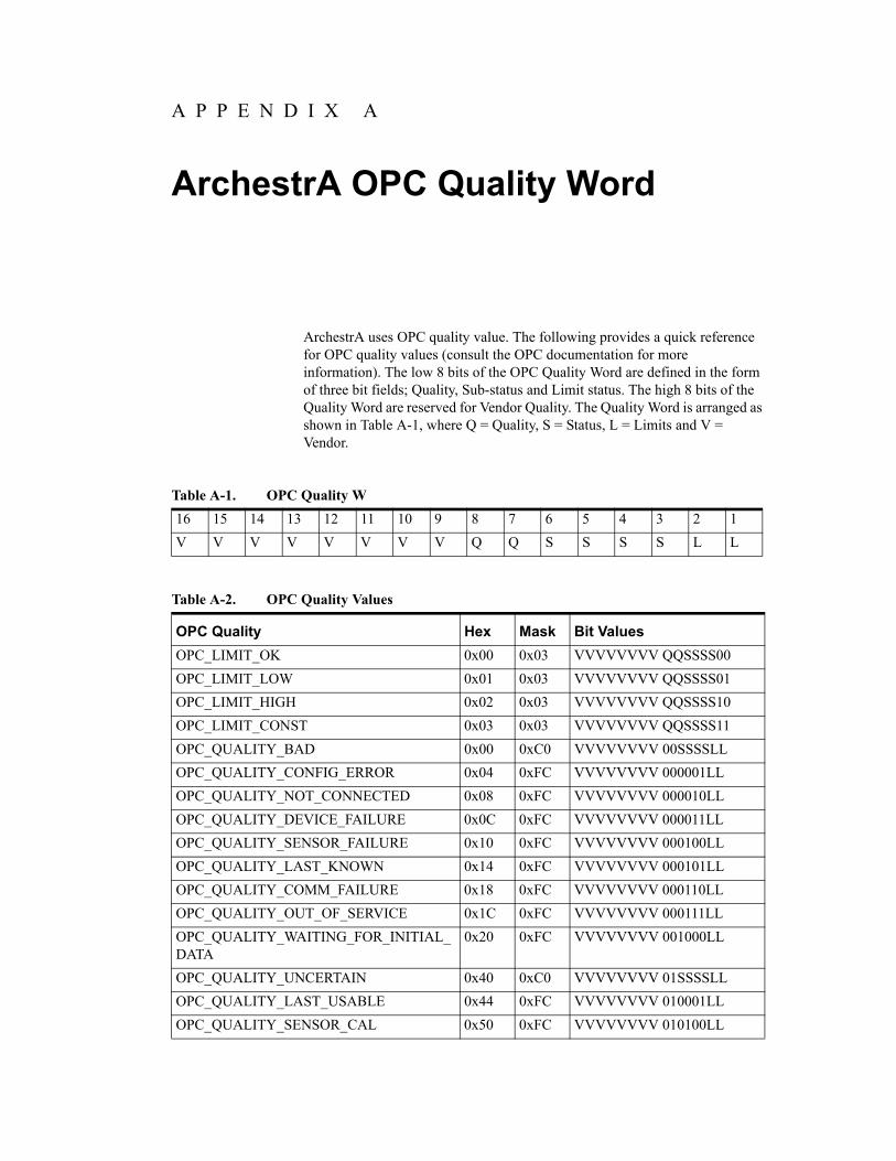
A P P E N D I X A
ArchestrA OPC Quality Word
ArchestrA uses OPC quality value. The following provides a quick reference for OPC quality values (consult the OPC documentation for more information). The low 8 bits of the OPC Quality Word are defined in the form of three bit fields; Quality, Sub-status and Limit status. The high 8 bits of the Quality Word are reserved for Vendor Quality. The Quality Word is arranged as shown in Table A-1, where Q = Quality, S = Status, L = Limits and V = Vendor.
Table A-1. OPC Quality W
16 15 14 13 12 11 10 9 8 7 6 5 4 3 2 1
V V V V V V V V Q Q S S S S L L
Table A-2. OPC Quality Values
OPC Quality Hex Mask Bit Values
OPC_LIMIT_OK 0x00 0x03 VVVVVVVV QQSSSS00
OPC_LIMIT_LOW 0x01 0x03 VVVVVVVV QQSSSS01
OPC_LIMIT_HIGH 0x02 0x03 VVVVVVVV QQSSSS10
OPC_LIMIT_CONST 0x03 0x03 VVVVVVVV QQSSSS11
OPC_QUALITY_BAD 0x00 0xC0 VVVVVVVV 00SSSSLL
OPC_QUALITY_CONFIG_ERROR 0x04 0xFC VVVVVVVV 000001LL
OPC_QUALITY_NOT_CONNECTED 0x08 0xFC VVVVVVVV 000010LL
OPC_QUALITY_DEVICE_FAILURE 0x0C 0xFC VVVVVVVV 000011LL
OPC_QUALITY_SENSOR_FAILURE 0x10 0xFC VVVVVVVV 000100LL
OPC_QUALITY_LAST_KNOWN 0x14 0xFC VVVVVVVV 000101LL
OPC_QUALITY_COMM_FAILURE 0x18 0xFC VVVVVVVV 000110LL
OPC_QUALITY_OUT_OF_SERVICE 0x1C 0xFC VVVVVVVV 000111LL
OPC_QUALITY_WAITING_FOR_INITIAL_DATA
0x20 0xFC VVVVVVVV 001000LL
OPC_QUALITY_UNCERTAIN 0x40 0xC0 VVVVVVVV 01SSSSLL
OPC_QUALITY_LAST_USABLE 0x44 0xFC VVVVVVVV 010001LL
OPC_QUALITY_SENSOR_CAL 0x50 0xFC VVVVVVVV 010100LL
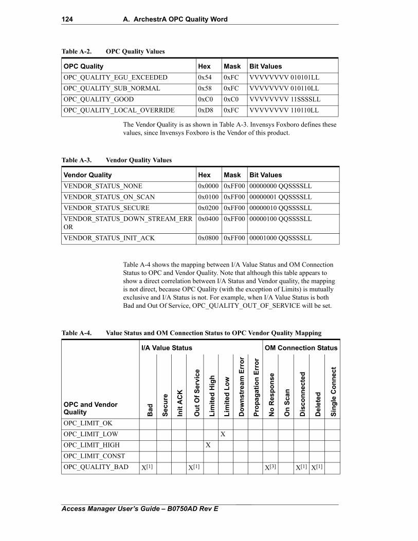
124 A. ArchestrA OPC Quality Word
The Vendor Quality is as shown in Table A-3. Invensys Foxboro defines these values, since Invensys Foxboro is the Vendor of this product.
Table A-4 shows the mapping between I/A Value Status and OM Connection Status to OPC and Vendor Quality. Note that although this table appears to show a direct correlation between I/A Status and Vendor quality, the mapping is not direct, because OPC Quality (with the exception of Limits) is mutually exclusive and I/A Status is not. For example, when I/A Value Status is both Bad and Out Of Service, OPC_QUALITY_OUT_OF_SERVICE will be set.
OPC_QUALITY_EGU_EXCEEDED 0x54 0xFC VVVVVVVV 010101LL
OPC_QUALITY_SUB_NORMAL 0x58 0xFC VVVVVVVV 010110LL
OPC_QUALITY_GOOD 0xC0 0xC0 VVVVVVVV 11SSSSLL
OPC_QUALITY_LOCAL_OVERRIDE 0xD8 0xFC VVVVVVVV 110110LL
Table A-2. OPC Quality Values
OPC Quality Hex Mask Bit Values
Table A-3. Vendor Quality Values
Vendor Quality Hex Mask Bit Values
VENDOR_STATUS_NONE 0x0000 0xFF00 00000000 QQSSSSLL
VENDOR_STATUS_ON_SCAN 0x0100 0xFF00 00000001 QQSSSSLL
VENDOR_STATUS_SECURE 0x0200 0xFF00 00000010 QQSSSSLL
VENDOR_STATUS_DOWN_STREAM_ERROR
0x0400 0xFF00 00000100 QQSSSSLL
VENDOR_STATUS_INIT_ACK 0x0800 0xFF00 00001000 QQSSSSLL
Table A-4. Value Status and OM Connection Status to OPC Vendor Quality Mapping
I/A Value Status OM Connection Status
OPC and Vendor Quality B
ad
Se
cu
re
Init
AC
K
Ou
t O
f S
erv
ice
Lim
ite
d H
igh
Lim
ite
d L
ow
Do
wn
str
ea
m E
rro
r
Pro
pa
ga
tio
n E
rro
r
No
Re
sp
on
se
On
Sc
an
Dis
co
nn
ec
ted
Del
eted
Sin
gle
Co
nn
ect
OPC_LIMIT_OK
OPC_LIMIT_LOW X
OPC_LIMIT_HIGH X
OPC_LIMIT_CONST
OPC_QUALITY_BAD X[1] X[1] X[3] X[1] X[1]
Access Manager User’s Guide – B0750AD Rev E
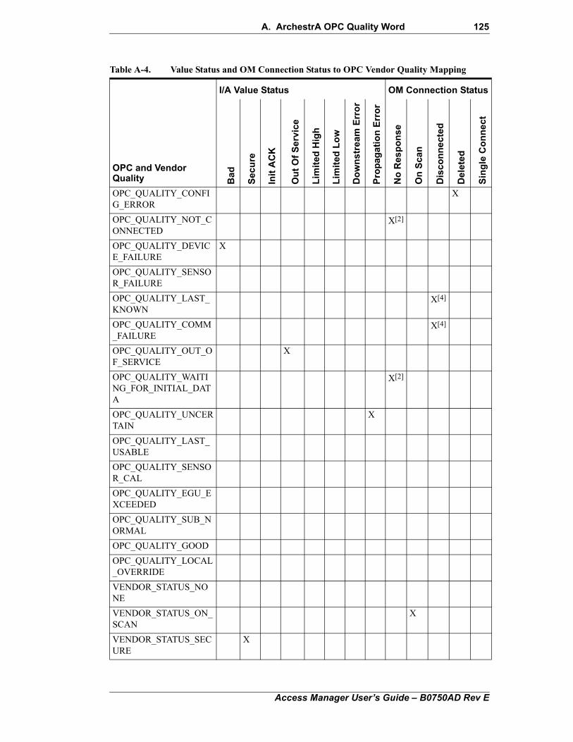
A. ArchestrA OPC Quality Word 125
OPC_QUALITY_CONFIG_ERROR
X
OPC_QUALITY_NOT_CONNECTED
X[2]
OPC_QUALITY_DEVICE_FAILURE
X
OPC_QUALITY_SENSOR_FAILURE
OPC_QUALITY_LAST_KNOWN
X[4]
OPC_QUALITY_COMM_FAILURE
X[4]
OPC_QUALITY_OUT_OF_SERVICE
X
OPC_QUALITY_WAITING_FOR_INITIAL_DATA
X[2]
OPC_QUALITY_UNCERTAIN
X
OPC_QUALITY_LAST_USABLE
OPC_QUALITY_SENSOR_CAL
OPC_QUALITY_EGU_EXCEEDED
OPC_QUALITY_SUB_NORMAL
OPC_QUALITY_GOOD
OPC_QUALITY_LOCAL_OVERRIDE
VENDOR_STATUS_NONE
VENDOR_STATUS_ON_SCAN
X
VENDOR_STATUS_SECURE
X
Table A-4. Value Status and OM Connection Status to OPC Vendor Quality Mapping
I/A Value Status OM Connection Status
OPC and Vendor Quality B
ad
Se
cu
re
Init
AC
K
Ou
t O
f S
erv
ice
Lim
ited
Hig
h
Lim
ited
Lo
w
Do
wn
stre
am E
rro
r
Pro
pag
ati
on
Err
or
No
Re
sp
on
se
On
Sca
n
Dis
co
nn
ect
ed
Del
eted
Sin
gle
Co
nn
ect
Access Manager User’s Guide – B0750AD Rev E
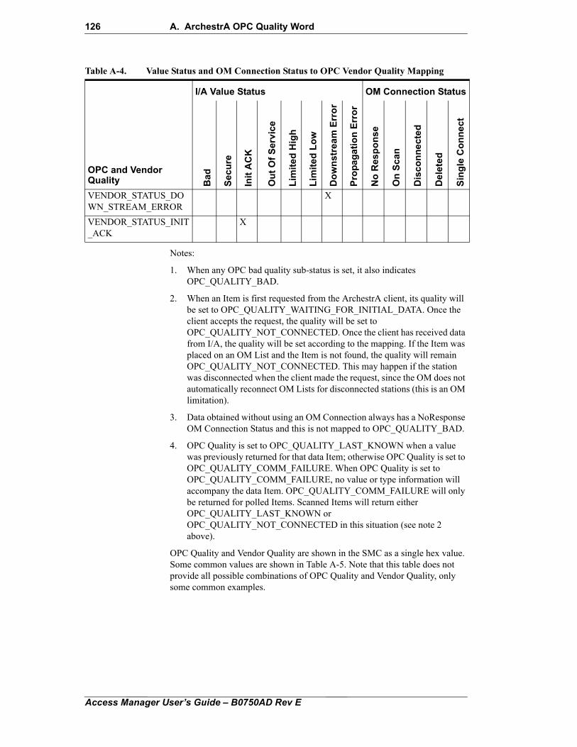
126 A. ArchestrA OPC Quality Word
Notes:
1. When any OPC bad quality sub-status is set, it also indicates OPC_QUALITY_BAD.
2. When an Item is first requested from the ArchestrA client, its quality will be set to OPC_QUALITY_WAITING_FOR_INITIAL_DATA. Once the client accepts the request, the quality will be set to OPC_QUALITY_NOT_CONNECTED. Once the client has received data from I/A, the quality will be set according to the mapping. If the Item was placed on an OM List and the Item is not found, the quality will remain OPC_QUALITY_NOT_CONNECTED. This may happen if the station was disconnected when the client made the request, since the OM does not automatically reconnect OM Lists for disconnected stations (this is an OM limitation).
3. Data obtained without using an OM Connection always has a NoResponse OM Connection Status and this is not mapped to OPC_QUALITY_BAD.
4. OPC Quality is set to OPC_QUALITY_LAST_KNOWN when a value was previously returned for that data Item; otherwise OPC Quality is set to OPC_QUALITY_COMM_FAILURE. When OPC Quality is set to OPC_QUALITY_COMM_FAILURE, no value or type information will accompany the data Item. OPC_QUALITY_COMM_FAILURE will only be returned for polled Items. Scanned Items will return either OPC_QUALITY_LAST_KNOWN or OPC_QUALITY_NOT_CONNECTED in this situation (see note 2 above).
OPC Quality and Vendor Quality are shown in the SMC as a single hex value. Some common values are shown in Table A-5. Note that this table does not provide all possible combinations of OPC Quality and Vendor Quality, only some common examples.
VENDOR_STATUS_DOWN_STREAM_ERROR
X
VENDOR_STATUS_INIT_ACK
X
Table A-4. Value Status and OM Connection Status to OPC Vendor Quality Mapping
I/A Value Status OM Connection Status
OPC and Vendor Quality B
ad
Se
cu
re
Init
AC
K
Ou
t O
f S
erv
ice
Lim
ite
d H
igh
Lim
ite
d L
ow
Do
wn
stre
am
Err
or
Pro
pa
ga
tio
n E
rro
r
No
Res
po
ns
e
On
Sc
an
Dis
co
nn
ec
ted
Del
eted
Sin
gle
Co
nn
ect
Access Manager User’s Guide – B0750AD Rev E
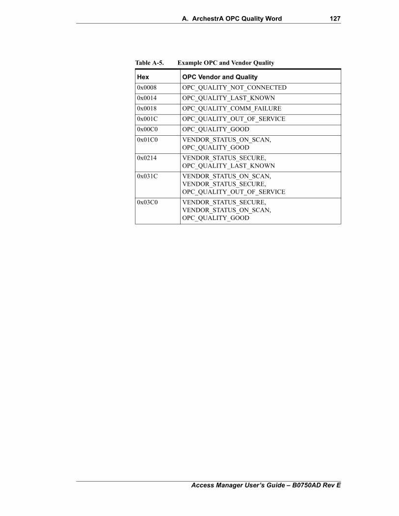
A. ArchestrA OPC Quality Word 127
Table A-5. Example OPC and Vendor Quality
Hex OPC Vendor and Quality
0x0008 OPC_QUALITY_NOT_CONNECTED
0x0014 OPC_QUALITY_LAST_KNOWN
0x0018 OPC_QUALITY_COMM_FAILURE
0x001C OPC_QUALITY_OUT_OF_SERVICE
0x00C0 OPC_QUALITY_GOOD
0x01C0 VENDOR_STATUS_ON_SCAN, OPC_QUALITY_GOOD
0x0214 VENDOR_STATUS_SECURE, OPC_QUALITY_LAST_KNOWN
0x031C VENDOR_STATUS_ON_SCAN, VENDOR_STATUS_SECURE, OPC_QUALITY_OUT_OF_SERVICE
0x03C0 VENDOR_STATUS_SECURE, VENDOR_STATUS_ON_SCAN, OPC_QUALITY_GOOD
Access Manager User’s Guide – B0750AD Rev E

128 A. ArchestrA OPC Quality Word
Access Manager User’s Guide – B0750AD Rev E
129
IndexA
access extensions 63accessing I/A Series data 52Alarm Database Size in the Process Alarm Database tab 95Alarm Priority Mapping in the Process Alarm Database tab 95alarms
configuring I/A Series Alarm Provider 93configuring system alarms in the I/A Series Alarm Provider 95configuring the process alarm database 93deploying and undeploying I/A Series Alarm Provider 92I/A Series Alarm Provider installation 92
Attribute Browser tab in the Galaxy Browser 1
B
BatchSize in the Sync Service configuration file 103bit data extensions 68block parameters in I/A Series tags 29, 53Block Read and Block Write tabs
exporting and importing blocks 42Block Read tab 43Block Write tab 44
C
collecting workstation for Wonderware Historian 84compound parameter in I/A Series tags 29, 53configuration files for the Galaxy Sync Service 102Configuration Generator 15configuring historian connections 84configuring the I/A Series Device Integration Object 36configuring the I/A Series History Provider 78configuring the IADAS 39Connection heartbeat period 38
D
DAServer tab for the I/A Series Device Integration Object 39data extensions to I/A Series tags 68
bit 68deadband 68mask 69status 69type 70
deadband data extensions 68Detect connection alarm 38Detect restart alarm 38Device Integration pane 12DI & Extensions view 12DI field in the I/A Series Browser 12DI Object in an I/A Series tag 28, 53DIConfiguration.xml 15Discard Sort Order in the Process Alarm Database tab 95
E
extensions 58access 63bit data extensions 68data 68deadband data extensions 68
Access Manager User’s Guide – B0750AD Rev E
130 Index
frequency 64mask data extensions 69packing 71status data extensions 69summary of tag extensions rules 60type data extensions 70
Extensions pane 13extensions to I/A Series tags
packing 71
F
FCS Configuration Tools 2FCS InTouch Application 1Force all Tag Names to Upper Case 38frequency extensions to I/A Series tags 64
G
Galaxy Browser 1Galaxy in an I/A Series tag 28, 53Galaxy Sync Service 99, 101
configuration file parameters 103configuring the Sync Agent 103custom configuration 102default security classification configuration 102features 100restarting the service 104software components 100
General tab for the I/A Series Device Integration Object 37
H
historization. See also I/A Series History Provider and Wonderware Historian 73HistoryMessageSize in the Sync Service configuration file 103
I
I/A Configuration pane 6I/A Series Alarm Provider 91
configuration 93configuring system alarms 95installation 92Process Alarm Database tab 93undeploying and deploying the I/A Series Alarm Provider object 92
I/A Series Browser 1cache configuration files 15Configuration Generator 15DI & Extensions view 12Extensions pane 13filtering the Parameter display 10hiding and showing columns in the Parameter pane 10hiding and showing strategies 6opening the browser from FCS Configuration Tools 2opening the browser from FCS InTouch Application 1opening the browser from InTouch WindowMaker 2Parameter pane 8Search view 7tab components 4Value field 14
I/A Series Data Access Server (IADAS) 19I/A Series Device Integration Object 19
configuring the object 36DAServer tab 39General tab 37
Access Manager User’s Guide – B0750AD Rev E
Index 131
installation 20Scan Group tab 26, 41
I/A Series History Provider 73configuring the application object 78implementing redundant collection 82specifying the collecting workstation for a compound 84
I/A Series Security Provider 119enabling security 121
IAConfiguration.xml 15IADAS 19
Block Read tab 43Block Write tab 44configuration 39system items for status and diagnostic information 54
IASeries in an I/A Series tag 53InSQL
selecting an Wonderware Historian Server for bulk storage 78starting and stopping the server 86
installation of the I/A Series Device Integration Object 20InTouch WindowMaker 2introduction viiItem in an I/A Series tag 29, 53
M
mask data extensions 69MutexLockEnable in the Sync Service configuration file 103
O
OM Deadband 41OM List Count Max 40OM List Count Reserved 40OM List Open Delay 41OM List Scan Rate Default 40OM List Size Max 40OM Simulation Mode 40
P
packing extensions 71Parameter pane in the I/A Series Browser 8
filtering the display 10hiding and showing columns 10
Priority 38Process Alarm Database tab 93
Alarm Database Size 95Alarm Priority Mapping 95Discard Sort Order 95
R
redundant collection for Wonderware Historian 82Refresh Date in the I/A Series Browser 15Refresh Security and History Databases 101refreshing the security and history databases 101Restart attempts 38Restart period 38Restart reset security 38Run server out-of-proc 38
S
Scan Group in an I/A Series tag 29, 53Scan Group tab for the I/A Series Device Integration Object 26, 41
Access Manager User’s Guide – B0750AD Rev E
132 Index
Scan groupsexporting and importing groups 42
Search view 7security 119
enabling security 121parameter based classifications 120security classification configuration files used by the Galaxy Sync Service 102
SecurityMessageSize in the Sync Service configuration file 103Server name 38Server node 38shared variables in I/A Series tags 29, 53status data extensions 69strategies 6Sync Agent configuration files 103SyncServerPort in the Sync Service configuration file 103system alarm areas 95System Items in IADAS 54
T
tag syntax 52topic in an I/A Series tag 53type data extensions 70
U
Use scan group name as access path 38
V
Value field in the I/A Series Browser 14Verifying 87
W
Wonderware Historian 73collecting platform and application engine statistics 81configuring historian connections 84configuring the I/A Series History Provider 78implementing redundant collection 82selecting an Wonderware Historian Server for bulk storage 78starting and stopping InSQL 86verifying history storage 87
Wonderware Historycollection attributes for block parameters and compound parameters 84
Access Manager User’s Guide – B0750AD Rev E

Index 133
Access Manager User’s Guide – B0750AD Rev E

Invens5601 GPlano,Unitedhttp://
GlobalInsideOutsidlocal IWebsit
ys Operations Managementranite Parkway Suite 1000
TX 75024 States of Americawww.iom.invensys.com
Customer Support U.S.: 1-866-746-6477e U.S.: 1-508-549-2424 or contact your nvensys representative.e: http://support.ips.invensys.com