flow modelling around propeller for a deep...
TRANSCRIPT

FLOW MODELLING AROUND PROPELLER FOR A DEEP DRAFTED VESSEL
IN VERY SHALLOW WATER
SYED MOHAMAD NAJMI BIN SYED TALIB
A thesis submitted in fulfilment of the
requirements for the award of the degree of
Master of Engineering (Marine Technology)
Faculty of Mechanical Engineering
Universiti Teknologi Malaysia
JANUARY 2014

To my beloved father and mother
ACKNOWLEDGEMENT
First, I would like to express my heartiest gratitude to Allah s.w.t for his bless in the completion of this thesis. No such thing is done without permission from Allah. Million thanks too dedicated to my parent for their huge support and keeping me updates with the study until completion and encouraging me both physically and spiritually.
Not to forget very much appreciation to a couple of individuals who extensively assisted me in completing this project, especially to my main supervisor, Dr. Agoes Priyanto for giving me loads of useful information, advice, comment and guidance through completing this thesis. Appreciation also dedicated to my cosupervisor, Dr Yasser, who sacrifices his precious time in guiding me towards mastering the field of Computational Fluid Dynamics. Finally, my second cosupervisor, Prof. Dr. Adi Maimun who fed me his piece of mind as well as expert recommendation and suggestion towards an accurate method in craving my thesis.
Thanks also to the Ministry of higher Education (MOHE), for providing financial support for this research, coded by R.J130000.7824.4F049. A condusive place for me to conduct this research, which is the Marine Technology Center (MTC), at Universiti Teknologi Malaysia.
Finally, a lot of thanks to all my fellow friends, those who have, in one way or another, assisting me weather direct or indirect towards the completion of this thesis.
ABSTRAK
Kod bendalir dinamik berkomputer (CFD) semakin mendapat sambutan kerana ianya merupakan satu medium yang efektif bagi memahami ciri-ciri aliran air, antaranya perolakan air di sekeliling kipas kapal. Justeru, tesis ini mempersembahkan model berangka bagi ciri-ciri aliran air pada bahagian buritan kapal LNG membabitkan kesan daripada kipas kapal dan kedalaman air yang cetek. Simulasi dibuat berpandukan model kipas kapal jenis B5-75 bergaris pusat (D) 7.7m yang telah direka dan diuji di MARIN, Netherland. Perisian ANSYS Fluent versi ke 12 digunakan bagi menyelesaikan persamaan RANS, manakala ICEM CFD digunakan untuk menjana grid isipadu serta permukaan yang direka. Grid yang dijana pada kipas kapal adalah jenis grid struktur tetra berselerak pada kawasan aliran air berdasarkan permukaan 3D tidak termampat persamaan Navier-Stokes. Dua jenis model perolakan aliran digunakan dalam perisian ANSYS Fluent, iaitu model biasa k-epsilon (k-e) untuk simulasi malar manakala pembawa daya rincih (SST) k-omega (k-rn) bagi simulasi tidak malar. Bagi perincian ruang simulasi, kipas kapal ditempatkan dalam dua silinder; silinder luar dan dalam yang masing-masing berdiameter sekata. Dua jenis ruang simulasi digunakan iaitu ruang statik (stator) dan ruang dinamik (rotor). Bagi ruang stator, jarak dari tempat air masuk ke bilah kapal adalah 2D, manakala jarak dari bilah ke air keluar adalah 6D. Diameter keliling adalah 3.6D. Bagi ruang rotor, jarak dari air masuk ke bilah adalah 0.2D manakala jarak aliran keluar berada dalam julat antara 0.4 dan 0.7D, serta diameter keliling sebanyak 1.4D. Simulasi air bergolak mengambil kira kedua-dua pendekatan rotor- stator, iaitu rujukan posisi pelbagai (MRF) serta kaedah grid gelincir (SD). Bandingan dilakukan melalui eksperimen dari jurnal-jurnal yang telah diterbitkan, serta kajian terperinci berkenaan kaedah kebergantungan terhadap simulasi berangka dan parameter berkomputer telah dilaksanakan. Prestasi kipas kapal bagi kes simulasi umumnya diramal dengan perbezaan kecil berbanding ekperimen di air lepas, kira- kira 10%, mungkin disebabkan strategi penjanaan grid , resolusi grid serta kualiti grid. Simulasi jaga dibuat terhadap kehadiran kemudi kapal yang diletakkan selepas kipas kapal dimana ianya menyebabkan kecekapan kipas kapal meningkat dan terus- menerus meningkat apabila kemudi diputar pada sudut -70 and -200. Kemudi bertindak menghapuskan pusaran air yang terhasil dari kipas kapal yang secara tidak langsung meningkatkan tujahan serta torknya. Seperti yang dijangka, berlaku prebezaan dari segi pengamatan halaju antara simulasi kipas kapal di air lepas dengan interaksi antara badan kapal dan kipas kapal. Kesan daripada kipas kapal dan kemudi terhadap butiran kelajuan air di sekitar buritan kapal LNG telah dikenalpasti dengan jelas. Dengan keutamaan pada kedalaman air paling cetek (h/T = 1.1), butiran halaju ekstrem tertumpu pada bahagian buritan kapal yang ditenggelami air serta bahagian dasar laut.

ABSTRACT
Computational fluid dynamics (CFD) codes, are recently used as efficient tools to understand flow characteristics such as wake development around propeller. This thesis presents numerical modelling of flow characteristics in the stern region for a deep drafted LNG carrier with the effect of propeller and rudder in shallow water. The modelling was conducted based on the B5-75 type propeller, with a diameter (D) of 7.7m, which was designed at MARIN in the Netherlands. The ANSYS Fluent version 12 software was used to solve the Reynold Averaged Navier Stokes (RANS) equations, and ICEM CFD as a mesh generator. The propeller was meshed using tetra unstructured mesh in a flow field based on 3D incompressible Navier-stokes solver. Two turbulent models were applied in the ANSYS Fluent; which are the standard k-epsilon (k-e) model for the steady simulation and transient shear stress transport (SST) k-omega (k-rn) for the unsteady simulation. For the computational domain, the propeller blades were mounted on two finite long constant radius cylinders. The two types of cylinder domains, were developed; stator domain and rotor domain. For the stator domain, the inlet flow was 2D from blade, the outlet flow at 6D and the outer boundary was 3.6D. The upstream for the rotor domain was maintained at 0.2D but the downstream was extended between 0.4D and0.7D, and the outer boundary at 1.4D. The turbulent model was simulated in the rotor domain by using the stator-rotor approaches such as the multiple reference frame (MRF) and the sliding mesh (SM) method. Comparisons with the published experiments were presented, and the dependence of the numerical solutions on the computational parameters was studied extensively. The thrust and torque of the propeller were generally predicted with a small error when it was compared with the published experiments. The difference in performance of propeller in the open water test is about 10 percent, likely due to mesh strategy as well as mesh resolution and quality. The performance of the propeller was also studied. It was found that the rudder placed in front of propeller increased the efficiency of the propeller and produced greater thrust increments when the rudder was deflected to -70 and -200. The presence of the rudder which acts by cancelling the trailing vortices from the tip of propeller slipstream leads to increase of thrust and torque of propeller. There was, as expected, a difference in the velocity concentration between propeller only and propeller-hull interaction. The effects of propeller and rudder on the velocity profiles in the region for the LNG carrier in shallow water are clearly identified. Especially in very shallow water, (h/T = 1.1), the extreme velocity profile is concentrated in vicinity of top part of the stern and seabed regions.

CHAPTER TITLE PAGE
DECLARATION ii
DEDICATION iii
ACKNOWLEDGEMENTS iv
ABSTRAK v
ABSTRACT vi
TABLE OF CONTENTS vii
LIST OF TABLES x
LIST OF FIGURES xii
LIST OF ABBREVIATIONS xviii
LIST OF SYMBOLS xx
LIST OF APPENDICES xxv
1 INTRODUCTION 1
1.1 Background 1
1.2 Problem statement 6
1.3 Objectives of the research 8
1.4 Thesis organization 8
2 LITERATURE REVIEW 12
2.1 CFD studies of propeller and rudder 16
2.1.1 Size of computational domain 22
2.1.2 Grid elements and mesh structure 24
2.1.3 Turbulence modelling 27
2.1.4 Influence of rotational domain approaches 30
2.1.5 Full scale and model scale computations 31
2.2 Propeller-rudder interaction 34
2.3 Influence of shallow water 40
2.4 Influence of non-uniform incoming wake (hull)
to rudder 42
3 RESEARCH METHODOLOGY 45
3.1 Methodology 45
3.2 Gantt chart 50
3.3 Research flowchart 51
3.4 Highlights of the study 52
4 MATHEMATICAL MODEL OF FLOW AROUND
PROPELLER 55
4.1 Problem definitions 55
4.1.1 Open water characteristics of propeller 56
4.1.2 Force and moment induced by rudder 56
4.1.3 Very shallow water effect 57
4.2 Numerical treatment 59
4.2.1 General RANS equation 59
4.2.2 The Standard k-e turbulence model 61
4.2.3 The SST k-rn turbulence model 63
4.2.4 SIMPLE pressure-velocity coupling 63
4.2.5 Simulation setup (ICEM CFD) 65
4.2.6 Simulation setup (ANSYS Fluent) 66
5 CFD SIMULATION : CASE STUDY 68
5.1 Ship hull form 68
5.2 The B-series propeller 71
5.2.1 Analytical propeller design using
standard series 73
5.2.2 Wgeningen B-series propeller construction 79

5.3 Rudder 84
5.4 Propeller open water test 87
5.5 Propeller-rudder-hull interaction 87
6 RESULTS AND DISCUSSION 90
6.1 Propeller open water test 90
6.1.1 Rotating/static stationary shaft conditions 94
6.1.2 Fresh water/salt water comparison 95
6.1.3 Influence of turbulence modeling 96
6.1.4 Influence of size of rotational domain 98
6.1.5 Open water test of the MARIN B4-58
propeller 102
6.2 Propeller-rudder Interactions 103
6.2.1 Propeller-rudder clearance 109
6.3 Propeller-hull interaction in shallow water 111
6.4 Propeller-rudder-hull interaction in shallow water 115
6.5 Flow visualization around propeller 119
6.5.1 Rudder pressure contours and surrounding
velocities 119
6.5.2 Axial velocity contours and vectors 127
6.5.3 Measurements between propeller and rudder 130
6.5.4 Flow pattern and velocity distribution
between propeller and rudder 140
7 CONCLUSIONS AND RECOMMENDATIONS 147
7.1 Conclusions 148
7.2 Recommendations 150
REFERENCES 152
APPENDICES 158

TABLE NO. TITLE PAGE
2.1 Thrust Coefficient, K T (Seo, 2010) 17
2.2 Torque Coefficient, K q (Seo, 2010) 18
2.3 Different dimensions of rotating domain 23
2.4 Verification study of K T and K q 25
3.1 Principal particulars of the Tenaga Class
LNG carrier (MTL 057) 54
5.1 Particulars required for propeller prediction 73
5.2 Resistance prediction of MTL 057 75
5.3 Measured data from BPS diagram of B5-75 78
5.4 Calculated c(r) and skew at 0.2R 80
5.5 Blade contour of the B-series propellers 80
5.6 Calculated blade section thickness, t(r) and position of
maximum thickness from leading edge, x tmax 81
5.7 Table of blade thickness of all sections at 0.2R 82
5.8 Calculated pitch angle at each corresponding radius of
the B5-88 propeller 83
5.9 Breakdown of the total maximum root tensile stress for
a set of four different vessels by Carlton (2007) 83
6.1 Various OWT computational configurations 92
6.2 OWT1 with rotating stationary shaft 94
6.3 OWT1 with static stationary shaft 95
6.4 OWT1 comparisons between fresh water and salt water 96
6.5 Thrust generation from various open water tests at J = 0.4 104
6.6 Open water properties for various propeller-rudder
interaction, OWT3 109
6.7 Open water parameters of propeller-rudder clearance 110
6.8 Efficiency and thrust coefficient comparison of
propeller-rudder interactions by Abramowski et al. (2010) 111
6.9 Propeller- hull interactions with different depth-draft ratios 112
6.10 Open water parameters for propeller-rudder-hull
interaction with various h/t and AoA at 13.01 knots 116
6.11 Open water parameters for hull-propeller-rudder
interactions with various h/t and AoA at 14.75 knots 117
6.12 Open water characteristics of propeller-rudder interactions,
AoA = 00 J = 0.4, 130.27rpm t = 0.00258862
at 180 time steps 134

FIGURE NO. TITLE
1.1 Phase diagram
1.2 Typical propeller cavitation at the back of the blade
surfaces, the helical tip and the central hub vortex
2.1 Configuration of the propeller and rudder and rudder
incident flow caused by propeller wake, starboard view
2.2 Typical rudder cavitations
2.3 Computational domain for propeller open water test by
Seo (2010)
2.4 Mesh structure of propeller and its surroundings
2.5 Distribution of AoA at the location of small rudder
blockage and deflection effects, and the rudder angle of 00.
by Paik et. al., (2012).
2.6 Photos of cavitation observation on semi-spade rudder
at the cavitation number of 1.50 by Paik et. al., (2012)
2.7 Computational domain of propeller open water by
Nakisa et al. (2010)
2.8 OWT result of SST k-rn with sliding mesh (SM) method by
Nakisa et al. (2010)
2.9 Computational open water results by Abramowski et. al.
(2010)
2.10 Different choices of rotating reference frame and velocity
streamlines distribution
2.11 Hexa fine surface mesh and hybrid mesh surface mesh
PAGE
6
7
13
14
16
17
18
19
20
21
22
23
2.12 Errors percentage of propeller and open water curves
of propeller A 26
2.13 Open water characteristics of P4119 by
Huang et. al.(2007) 28
2.14 Pressure contours on suction side, pressure side and
x-directional velocity contours of J =0.1 29
2.15 Hamburg test cases at full scale with an operating
propeller (0.21D in front of propeller) 33
2.16 Blocked and diverted flow by rudder by Jamali (2010) 35
2.17 Schematic diagram of rudder longitudinal inflow velocity 39
2.18 Definition of depth (h) and draught (T) and bottom
according to PIANC, (1992) 40
2.19 Percentage loss of speed in shallow water by
Lackenby (1963) 42
3.1 XZ plane indications of propeller- rudder region 48
3.2 The Tenaga class LNG carrier 54
5.1 MTL 057 body plan view 69
5.2 MTL 057 Profile View 69
5.3 MTL 057 Full breadth plan view 70
5.4 Rendering perspective view of the MTL 057 70
5.5 Body plan, stem and stern profiles of MTL 057
with draught of 11.13m both forward and aft 70
5.6 Graph of effective power versus ship’s speed in knots 75
5.7 BP-S diagram of B5-75 by Lewis, (1988) 77
5.8 Propulsion Factors for parent models of series 60
by Lewis (1988) 78
5.9 Definition of blade section parameters of B-series 81
5.10 Expanded view of B5-88 propeller 82
5.11 Typical marine rudders by Bertram et al. (2000) 84
5.12 Typical rudder geometry and arrangement 85
5.13 Computational domain of propeller open water test 87
5.14 Computational domain of hull-propeller-rudder interaction 88
5.15 Propeller, rudder and hull designated clearance 89

5.16 Hull-propeller-rudder clearance nomencalture
by Lloyd’s Register (2006) 89
6.1 Hull, propeller, and rudder configuration 91
6.2 Convergence criterion of J = 0.4 OWT3 steady k-s 93
6.3 Convergence criterion of J=0.4 OWT3 unsteady SST k-a 93
6.4 Graphs of efficiency curves 97
6.5 Graph of K T versus J for various computational domain
configurations 100
6.6 Graph of 10Kq versus J for various computational
domain configurations 100
6.7 Graph of ̂ versus J for various computational
domain configurations 101
6.8 Graph of K T, 10Kq, and ^ versus J for various
computational domain configurations for propeller B4-58 103
6.9 Angle of attack (AoA) definitions ahead of rudder leading
edge by Paik et al., (2012) 105
6.10 Convergence criterion of propeller-rudder interaction,
AoA =00, OWT3 steady k-s, J =0.4 105
6.11 Convergence criterion of propeller-rudder interaction,
AoA = 00 OWT3 unsteady SST k-a, J = 0.4 106
6.12 Graph of K T versus J, propeller-rudder interaction 107
6.13 Graph of 10Kq versus J, propeller-rudder interaction 107
6.14 Graph of ̂ versus J, propeller-rudder interaction 108
6.15 YZ plane velocity contours and vectors of X = 0.6494D
viewing from aft 114
6.16 Convergence criterion of hull-propeller-rudder interaction
of J=0.4, SST k-a, hm, 13.01 knots inflow speed 115
6.17 YZ plane velocity contours and vectors of X = -0.6494D
viewing from aft 118
6.18 Rudder pressure distribution, propeller-rudder interactions,
J = 0.4, inflow speed 13.01kn, starboard side 119
6.19 Rudder pressure distribution, propeller-rudder interactions,
J = 0.4, inflow speed 13.01kn, port side 120

6.20
6.21
6.22
6.23
6.24
6.25
6.26
6.27
6.28
6.29
6.30
6.31
6.32
6.33
6.34
6.35
Rudder pressure distribution, propeller-rudder interactions,
J = 0.4, inflow speed 13.01kn, ho, starboard side 121
Rudder pressure distribution, propeller-rudder-hull
interaction, J = 0.4, inflow speed 13.01kn, ho, port side 121
The deformation of tip vortices due to presence of rudder,
as seen in the experiment by Kracht, (1989). 122
Rudder pressure distribution, propeller-rudder interactions,
J = 0.4, inflow speed 13.01kn, h/T = 2.1, starboard side 123
Rudder pressure distribution, propeller-rudder interactions,
J = 0.4, inflow speed 13.01kn, h/T = 2.1, port side. 123
YZ plane velocity contours and vectors of
propeller-rudder-hull interaction at X = -0.6494D
(centre of rudder), h/T = 2.1 124
Rudder pressure distribution, propeller-rudder interactions,
J = 0.4, inflow speed 13.01kn, h/T = 1.3, starboard side. 124
Rudder pressure distribution, propeller-rudder interactions,
J = 0.4, inflow speed 13.01kn, h/T = 1.3, port side 125
Rudder pressure distribution, propeller-rudder interactions,
J = 0.4, inflow speed 13.01kn, h/T = 1.1, starboard side 125
Rudder pressure distribution, propeller-rudder interactions,
J = 0.4, inflow speed 13.01kn, h/T = 1.1, port side 126
YZ plane velocity contours and vectors of
hull-propeller-rudder interaction at X = -0.6494D
(centre of rudder), h/T = 1.1 126
Indications of YZ cross sectional views from XZ plane,
starboard side. 128
YZ plane, X-directional velocity contours, propeller-rudder
interaction. 129
Pressure contours of surrounding fluids starboard side view,
propeller-rudder interaction. 130
X-velocity versus X-distance from hub tip to rudder
leading edge for propeller-rudder interaction, Z= -0.7R. 131
X-velocity versus X-distance from hub tip to rudder leading
edge for propeller-rudder interaction, Z= +0.7R 131
6.36
6.37
6.38
6.39
6.40
6.41
6.42
6.43
6.44
6.45
6.46
6.47
6.48
6.49
XZ plane pressure contours of propeller-rudder-hull
interaction, starboard side view, AoA = 00. 132
X-velocity versus X-distance from hub tip to rudder leading
edge for propeller-rudder-hull interaction, AoA = 00 133
X directional velocity (solid line) velocity profiles in the
region between propeller hub and rudder leading edge,
propeller-rudder interaction, at the plane Z= +0.7R, phase
angle 1800 and AoA = 00 by Paik et. al. (2012). 134
X-velocity versus X-distance from hub tip to rudder
leading edge for hull-propeller-rudder interaction,
AoA = -200 135
XZ plane pressure contour between propeller and rudder,
propeller-rudder-hull interaction, starboard view,
AoA = -200 136
X-velocity versus X-distance from hub tip to rudder
leading edge, propeller-rudder-hull interaction, Z = +0.7R,
AoA = -200, starboard side view 137
XZ plane pressure contour between propeller and rudder,
propeller-rudder-hull interaction, starboard view,
AoA = -70. 138
X-velocity versus X-distance from hub tip to rudder
leading edge, propeller-rudder-hull interaction, Z = +0.7R,
AoA = -70. 139
XY plane of X-velocity contours and streamlines, Z= -0.7R,
propeller-rudder interaction, plan view. 140
XY plane of velocity contours and streamlines, AoA = 00 141
XY plane of X-velocity contours and streamlines,
propeller-rudder-hull interaction, AoA = -70, plan view 142
XY plane of X-velocity contours and streamlines,
AoA = -200, propeller-rudder-hull interaction 143
XY planes of X-velocity contours and streamlines,
propeller-rudder-hull interaction, plan view, hOT 144
XY planes of X-velocity contours and streamlines,
propeller-rudder-hull interaction, plan view, h/T = 2.1 144
6.50
6.51
XY plane of X-velocity contours and streamlines,
propeller-rudder-hull interaction, Z= -0.7R, plan view,
h /T =1.3 145
XY plane of X-velocity contours and streamlines,
propeller-rudder-hull interaction, Z= -0.7R, plan view,
h /T =1. 1 145

6DOF - Six degree of freedom
AMG - Algebraic multigrid method
AoA - Angle of attack
BEM - Boundary element method
CAD - Computer Aided Design
CFD - Computational Fluid Dynamics
CMT - Circular motion test
DNV - Det Norske Veritas
DTMB - United States navy combatant name
DTRC - Propeller model
EAR - Expanded Area Ratio
EFD - Experimental fluid dynamics
EFFORT - European Full-Scale Flow Research and Technology
IIHR - Iowa Institute of Hydraulic Research
IMO - International Maritime Organization
INSEAN - Instituto Nazionale per Studi ed Esperienze di Architettura
Navale
ITTC - International Towing Tank Conference
KCS - Korean container ship
KVLCC - Korean very large crude carrier
LE - Leading Edge
LES - Large Eddy Simulation
LNG - Liquified Natural Gas
MISC - Malaysia International Shipping Corporation
MRF - Multiple reference frame method
MTL - Marine technology lab (model code)

NACA - National Advisory Council for Aeronautics
PIANC - World Association for Waterborne Transport Infrastructure
PISO - Pressure-Implicit with Splitting of Operators
PIV - Particle image velocimetry
PMM - Planar motion mechanism
RANS - Reynolds averaged navier stokes
rpm - Rotation per minute
rps - Rotation per second
SGS - Subgrid Scale Model
SM - Sliding mesh
SSMB - Samsung Ship Model Basin
SST - Shear Stress Transport
TE - Trailing edge
UKC - Under keel clearance
UTM - Universiti Teknologi Malaysia
VLM - Vortex lattice method

FH
f d
f b
Ux
h<x
u v
Pc
r
v
Tij
Ar
Ax
Ae/Ao
aH
aH
Ar, Br
Ar
AR, min
B
b
bR
c
c(r)
ClE, C2E
Cb
Hull force
Propeller force
Rudder force
Acceleration in x-direction
Deep water/ infinite depth
Velocity in x-direction
Pressure correction
Dimensionless turning rate [r = r (L / U)]
Acceleration in y-direction
stress vector in vertical plane; x and y finite difference index
Increment in radius
Increment of force in forward (surge) direction
Blade area ratio
Ratio of additional lateral force
Transverse force
Coefficients (Kuiper, 1992)
Projected rudder area
Minimum projected rudder area
Beam/breadth
Source term of net flow rate into the cell
Rudder beam
Mean rudder chord length
Chord length
model constants
Block coefficient

cS - SGS model coefficient
Cs1 - Constant
CS2 - Constant
D - Diameter
Ddeep - Derivatives in deep water deduction fraction (Lewis, 1988)
dm - mean draft
Dmax - Propeller diameter behind hull
Do . Propeller diameter in open water
DP - Diameter of propeller
Dshw - Derivatives in shallow water
Dm - Cross-diffusion term
e - Mean distance between front edge of rudder and aft end of hull
E - Pressure-correction equation
f - As a function of
F - Force
f(h) - correcting factor
Fn - Rudder normal force
Fnh - Critical depth Froude number
G - Calculation grid
g - Gravitational acceleration
Gk - Generation of turbulence kinetic energy
Gm - Generation of rn
H - Hull, height
h - Water depth
h/T - Ratio of depth to draft
H2 - Rudder height
hR - Rudder height
Izz - Moment of inertia of the ship around Z-axis
J - Advance coefficient
J*f - Resulting face flux
J ’f - correction
Jf - corrected face flux
k - Turbulent kinetic energy
K(r) - Constant
K q - Torque coefficient
kR - Constant
K t - Thrust coefficient
k-s - Kind of turbulence model
k-a - Kind of turbulence model
L - Longitudinal distance; length between perpendiculars (Seo,
2010)
Lbr - distance from the centre of propeller hub to rotor outlet
LE - Leading edge
Lfr - distance from the centre of propeller hub to rotor inlet
LPP - Length between perpendiculars
Lsi - horizontal distance from centre of propeller hub to stator inlet
Lso - horizontal distance from centre of propeller hub to stator outlet
m - Mass of ship
N - Moment (yaw movement)
n - Revolution
Nr - Hydrodynamic derivatives
nR - Number of rudder
P - production of turbulence kinetic energy; Propeller
p* - pressure field
P/D - Pitch diameter ratio
p ’ - cell pressure correction
PD - Delivered power
PE - Estimated power
PS - Shaft power
Q - Torque
r - Angular velocity; slipstream radius (Bertram et al., 2000)
R - Rudder
r/R - Ratio of local radius to global radius
Rn - Reynolds number
rx - Slipstream radius in forward (surge) direction
Sk , Sa - User defined source terms
t - Draught; time (Guo et. al., 2010); thickness (Kuiper, 1992);
thrust

t
t(r)
TE
tr
tR
Ur
V
A
Va
A corr
Vcorr
A eff
Ageom
Vm
Vs
Vx
w
WR
X
xH
Xr
xtmax
Y
Yr
z
z
a
ak
ap
as
Thrust (eq. 4.1); Draft of ship (Bertram et al., 2000; Soding,
1982)
Thrust deduction fraction
Blade section thickness
Trailing edge
Blade thickness
Coefficient for additional drag
Longitudinal inflow velocity of rudder
Cell volume (Huang et. al., 2007); velocity (Bertram et al.,
2000)
rudder aspect ratio
Advance speed
Corrected rudder aspect ratio
mean axial speed over slipstream cross section
effective rudder aspect ratio
Geometrical rudder aspect ratio
Model speed of ship
Ship’s speed
Velocity at a distance behind propeller plane
Wake fraction
Rudder wake fraction
Longitudinal/surge force, axis
longitudinal distance from amidships to rudder position
distance between the centre of gravity of ship and centre of
lateral
Position of maximum thickness from leading edge
lateral/sway force, axis
Hydrodynamic derivatives
Number of blade
Number of blades, axis
Angle of attack
inverse effective Prandtl number of k
Under relaxation factor for pressure
Stall angle
ae - inverse effective Prandtl number of e
5 - Rudder angle
Sij - Kronecker delta
s - Dissipation ratio of k
n - Open water efficiency
nD - Delivered efficiency
nR - Relative rotative efficiency
nS - Shaft transmission efficiency
fj.eff - turbulent viscosity
p - Density
Tk - Effective diffusivity of k
Ta - Effective diffusivity of a
u - Kinetic viscosity of water
^ - Open w ater efficiency
6 - Pitch angle
- p u i 'uj' - Reynolds stresses
APPENDIX TITLE PAGE
A1 MTL 057 Lines Plan 159
A2 Lines plan drawing of B5-88 propeller 160
A3 Lines plan drawing of the rudder for MTL 057 161
A4 MARIN propeller B4-58 (modified) Lines Plan 162
B1 Propeller construction using the Wageningen
B-series (5 blades) 163
B2 Open water performance (Influence of size
of rotational domain) 167
C Convergence Criterion (Propeller-Rudder
Interaction) 170
D Surface mesh presentation (ICEM CFD) 172
E ' Visualization of radial velocity contours
and vectors of R= 1.2987D (aft view) 178

CHAPTER 1
INTRODUCTION
1.1 Background
A marine propeller is often operating in asymmetrical flow field, thus its
blades are subject to unsteady flow. Depending on the operating condition, such as
ship speed, and manoeuvring condition, the propeller may experience such
hydrodynamic phenomenon. But, if we take into consideration the safety aspect and
surrounding effect, the condition of water, water depth, objects passing nearby, it
become a complex situation and thus an essential study towards the aforementioned
effect is included for a precise ship manoeuvring condition.
When designing a propeller, a general understanding of ship manoeuvring has
to be understood primarily for researchers, as well as naval architects and
hydrodynamic designers. Generally, manoeuvrability is about safety and economic
navigation. In detail, it is the ability of a ship to keep or change its motion under the
rudder control action. Systematically defined using the coordinate system, an
equation of ship motion can be possibly formed. Considering the interest motion,
longitudinal (surge), lateral (sway) and moment (yaw), the hydrodynamic forces
acting on the hull due to ship’s velocity and acceleration, rudder deflection/angle of
attack and propeller rotation can be assessed based on the equation of motion. The

prediction of ship manoeuvrability has been one of the difficult topics in the field of
ship hydrodynamics, due to its unsteady flow and nonlinear ship behaviour. In fact,
manoeuvrability of a ship signifies the predictability and controllability of the ship
motion in various sea conditions. Indeed, the interaction between hull, propeller and
rudder has a significant bearing on the manoeuvrability of a ship (Osman and
Hasegawa, 2010). The International Maritime Organization (IMO) has provided a
guideline that must be followed by both ship-owners as well as shipbuilders
regarding requirements for safe manoeuvring criteria during the manoeuvring
prediction of ships being built. The conventional method of predicting the
manoeuvring behaviour of a ship has been applied for decades due to its reliability
and fair accuracy.
The manoeuvrability of ship is measured qualitatively through determination
of the incurred upon hydrodynamic forces and moments by varying flow patterns
around the ship. Concerning the hydrodynamic coefficients, it comprises of
hydrodynamic forces and moments. On the other hand, hydrodynamic forces are
functions of velocities and accelerations that involved in a motion.
m x (Ux — v r ) = X (1.1)
m x (v + Uxr) = Y (1.2)
Izzx r = N (1.3)
Equations 1.1 - 1.3 addresses the basic balance equation of motion. Letter X
acts as the longitudinal force (surge), Y being the lateral force (sway), and finally N
stands for moment (yaw). The total hydrodynamic force is consists of three; the hull,
propeller and rudder. The first part only deals with hull hydrodynamic force. The
second part considers rudder forces, which depends on the rudder angle of attack.
The last part of hydrodynamic force is resistance and thrust change that caused by
speed loss during manoeuvring. It determines the difference between forward speed
of centre of gravity and water speed near rudder.
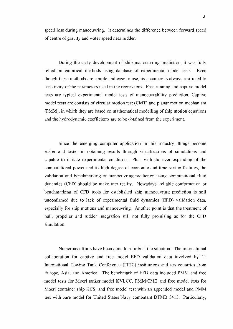
During the early development of ship manoeuvring prediction, it was fully
relied on empirical methods using database of experimental model tests. Even
though these methods are simple and easy to use, its accuracy is always restricted to
sensitivity of the parameters used in the regressions. Free running and captive model
tests are typical experimental model tests of manoeuvrability prediction. Captive
model tests are consists of circular motion test (CMT) and planar motion mechanism
(PMM), in which they are based on mathematical modelling of ship motion equations
and the hydrodynamic coefficients are to be obtained from the experiment.
Since the emerging computer application in this industry, things become
easier and faster in obtaining results through visualizations of simulations and
capable to imitate experimental condition. Plus, with the ever expanding of the
computational power and its high degree of economic and time saving features, the
validation and benchmarking of manoeuvring prediction using computational fluid
dynamics (CFD) should be make into reality. Nowadays, reliable conformation or
benchmarking of CFD tools for established ship manoeuvring prediction is still
unconfirmed due to lack of experimental fluid dynamics (EFD) validation data,
especially for ship motions and manoeuvring. Another point is that the treatment of
hull, propeller and rudder integration still not fully promising as for the CFD
simulation.
Numerous efforts have been done to refurbish the situation. The international
collaboration for captive and free model EFD validation data involved by 11
International Towing Tank Conference (ITTC) institutions and ten countries from
Europe, Asia, and America. The benchmark of EFD data included PMM and free
model tests for Moeri tanker model KVLCC, PMM/CMT and free model tests for
Moeri container ship KCS, and free model test with an appended model and PMM
test with bare model for United States Navy combatant DTMB 5415. Particularly,
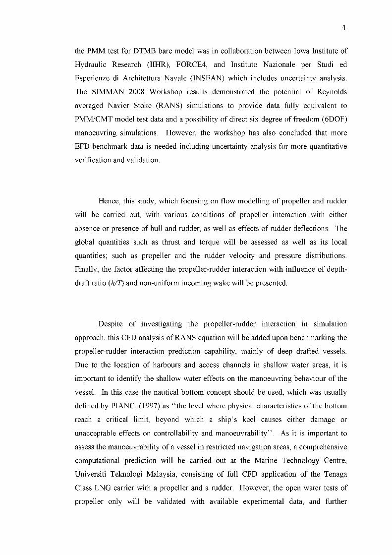
the PMM test for DTMB bare model was in collaboration between Iowa Institute of
Hydraulic Research (IIHR), FORCE4, and Instituto Nazionale per Studi ed
Esperienze di Architettura Navale (INSEAN) which includes uncertainty analysis.
The SIMMAN 2008 Workshop results demonstrated the potential of Reynolds
averaged Navier Stoke (RANS) simulations to provide data fully equivalent to
PMM/CMT model test data and a possibility of direct six degree of freedom (6DOF)
manoeuvring simulations. However, the workshop has also concluded that more
EFD benchmark data is needed including uncertainty analysis for more quantitative
verification and validation.
Hence, this study, which focusing on flow modelling of propeller and rudder
will be carried out, with various conditions of propeller interaction with either
absence or presence of hull and rudder, as well as effects of rudder deflections. The
global quantities such as thrust and torque will be assessed as well as its local
quantities; such as propeller and the rudder velocity and pressure distributions.
Finally, the factor affecting the propeller-rudder interaction with influence of depth-
draft ratio (h/T) and non-uniform incoming wake will be presented.
Despite of investigating the propeller-rudder interaction in simulation
approach, this CFD analysis of RANS equation will be added upon benchmarking the
propeller-rudder interaction prediction capability, mainly of deep drafted vessels.
Due to the location of harbours and access channels in shallow water areas, it is
important to identify the shallow water effects on the manoeuvring behaviour of the
vessel. In this case the nautical bottom concept should be used, which was usually
defined by PIANC, (1997) as “ the level where physical characteristics of the bottom
reach a critical limit, beyond which a ship’s keel causes either damage or
unacceptable effects on controllability and manoeuvrability’’. As it is important to
assess the manoeuvrability of a vessel in restricted navigation areas, a comprehensive
computational prediction will be carried out at the Marine Technology Centre,
Universiti Teknologi Malaysia, consisting of full CFD application of the Tenaga
Class LNG carrier with a propeller and a rudder. However, the open water tests of
propeller only will be validated with available experimental data, and further
validated with other kind of propeller as control data. Discussing about the global
quantities based on the results of similar open water tests, the hydrodynamic
coefficients for propeller and propeller -rudder interaction can be obtained. The
hydrodynamic forces induced by hull (H), propeller (P) and rudder (R) are analysed
separately. The total force F a ship is subjected to is found by superposition:
F = F v + F + F d (14)
With this mathematical model, it is possible to assess the flow around
propeller and rudder in shallow water by means of fast-time simulation runs of
standard manoeuvres. The present project will evaluate the forces induced by the
propeller as affected by the hull as well as the rudder. Furthermore, the investigation
also concerns with the local quantities. Numerous samples will be taken out in terms
of pressure and velocity contours, as well as streamlines and velocity vectors. The
behaviour of these local quantities is being discussed with the effect of rudder
deflections and also the effect of h/T.
Plus, a topic regarding cavitation towards rudder will be discussed in brief.
Cavitation is a situation in which zero pressure formed due to velocity halt or
stagnated. As a result, bubbles are formed and this creates oxidation to the
submerged part which leads to erosion. It happened due to flow of fluid with
significant velocity passing complicated geometries. Cavitation causes a lot of
problems, such as performance decrement, erosion, and noise. Theoretical methods
or model experiments are featured methods towards prediction of cavitation
inception of the submerged parts. However, the theoretical method requires various
assumptions and is less reliable when there are significant changes in the flow
conditions, while model experiments are more expensive and require time for model
building, especially when multiple models are required. To eliminate these
disadvantages, CFD is used to estimate the occurrence of cavitation by performing a
flow analysis around a propeller that rotates at the rear of a hull, while considering
the hull and rudder simultaneously.
1.2 Problem Statement
Despite the fact that in most cases the inflow is asymmetrical, the mean
marine propeller has often been predicted in steady flow. The steady flow that passes
the propeller creates a pressure field surrounding the propeller resulting in some sort
of excitation which pushes the hull forward, known as the propulsive force.
Unfortunately, these pressure fields are located on the rotating body, and they are not
constant, caused by fluctuate wake from behind hull. Since these pressure fields
rotate in the vicinity of a rigid body, the latter is prone to being excited.
Phase Diagram
LiquidSolid c: |o I1 -f—' 11 &4_I
1 j h w
1 TVapourTriple Point
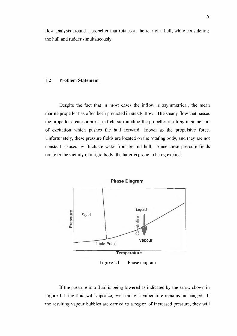
Temperature Figure 1.1 Phase diagram
If the pressure in a fluid is being lowered as indicated by the arrow shown in
Figure 1.1, the fluid will vaporize, even though temperature remains unchanged. If
the resulting vapour bubbles are carried to a region of increased pressure, they will
suddenly collapse. The surrounding fluid will very suddenly rush into the previously
void region. However, bubbles will not entirely collapse, but their remains may in
fact rebound. The cavitation may not only be present on the propeller itself, but also
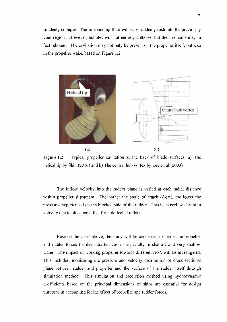
in the propeller wake, based on Figure 1.2.
(a) (b)
Figure 1.2 Typical propeller cavitation at the back of blade surfaces. a) The
helical tip by Shin (2010) and b) The central hub vortex by Lee et. al (2003)
The inflow velocity into the rudder plane is varied at each radial distance
within propeller slipstream. The higher the angle of attack (AoA), the lower the
pressures experienced on the blocked side of the rudder. This is caused by abrupt in
velocity due to blockage effect from deflected rudder.
Base on the cases above, the study will be concerned to model the propeller
and rudder forces for deep drafted vessels especially in shallow and very shallow
water. The impact of working propeller towards different AoA will be investigated.
This includes, monitoring the pressure and velocity distribution of cross sectional
plane between rudder and propeller and the surface of the rudder itself through
simulation method. This simulation and prediction method using hydrodynamic
coefficients based on the principal dimensions of ships are essential for design
purposes in accounting for the effect of propeller and rudder forces.
1.3 Objectives of the research
The objective of the study is to conduct a robust and computational stable
numerical method using ANSYS Fluent software which can predict the propeller
flow in various conditions. This includes the hydrodynamic performance, the
interactions between propeller and rudder, and finally the flow behaviour from
behind hull and decreasing water depth.
The second objective is to detect in specific the locations of extreme
pressures and velocities as well as series of irregular flows that appears from results
of simulations. This is further strengthened with aid of comparisons with previous
experimental and other references results.
1.4 Thesis Organization
The thesis is organised into seven main chapters. Chapter one contains
background, problem statements and objectives of this study.
Chapter two introduces past studies followed by brief information regarding
cavitation. CFD applications are presented featuring numerous previous efforts that
has been made towards investigation of propeller and rudder. Various numerical
methods involved upon investigating the propeller-rudder interactions are also
presented and evaluated; featuring the mesh strategy, computational domains,
treatments behind turbulence model, and effects of shallow water. These previous
findings cover a general understanding of the propeller-rudder interactions with a
number of proposed approaches dealing with propeller-rudder interaction as well as
their drawbacks and improvements.
In Chapter three, a detail methodology or research planning is described, starts
with thorough study of propeller and rudder behaviour, methods of investigations,
steps in acquiring hydrodynamic forces and moments and numerical method. The
model selection, together with propeller and rudder design and integration plan, will
be carried out upon. Then, numerical simulation water tests as well as propeller-
rudder interaction tests will be carried out via CFD approach. The resulting global
and local measurements will be discussed by focusing the pressure and velocity
impacts sourcing from various propeller-rudder configurations. Conclusion and
recommendation especially regarding safety measures and performance based on
discussion will be made for future research. Research frameworks are presented in a
form type of Gantt chart and a process tree for a thorough view regarding this
research. Finally, highlights of the current research is presented based on assessments
of prescribes findings.
In Chapter four, flow modelling around propeller involved in the study is
presented. Problem definitions of open water analysis; such as advance coefficient,
thrust and torque, as well as open water efficiencies are explained since the numerical
equation will be used to construct such an open water curve. Also, featured
equations involved in the calculation of forces and moments of propeller and rudder
are included for further understanding regarding their operations. A perturbing
equation of shallow water effect is also included to give us insight upon shallow
water effect. Numerical treatment that is involved in the calculation is presented.
Initially, the general RANS model is presented in explaining how the simulation
calculated the flow passing through the propeller and rudder. These involve
continuity, momentum, and energy equations. The turbulence model as well as
pressure-velocity coupling equations are also included to view the calculation
operation behind the numerical calculation. Finally, simulation setup is explained;
starting from grid generation to simulation options. Detail description upon kinds of
materials, cell zone conditions, mesh interface, reference values, solution method,
and finally calculation activities are to be discussed here.

Chapter five selects the case study of ship hull forms, propeller and rudder.
After selection of suitable model, construction drawing via computer aided design is
carried out for hull. For propeller design, analytical study is carried out first to suit
the propeller with the designated hull. The construction of propeller was based on
procedures provided by the Wageningen B-series propeller. Finally, rudder design is
done by altering the default semi spade rudder of the designated ship into full spade
rudder of very similar dimensions. Computational configurations of the open water
test are also presented, as well as for propeller-rudder-hull interactions.
Chapter six presents the results and discussion, three main tests are being
testified; the propeller open water, and propeller-rudder interaction, and effect of non
-uniform incoming wake pattern. For the first part, which is the propeller open water
test, another two categories are being studied; the steady calculation as well as
transient calculation and both approached are compared with available experiment
data. Effect of either fixed or rotating shaft inside stationary domain, fresh/salt water
comparison, influence of turbulence modelling and rotational domain method, size of
rotational domain are assessed in searching for best suitable simulation properties.
Another propeller is also being tested, for further clarification of reliability of the
prescribed method. Then, propeller-rudder interaction study is carried out, based on
previous parameters, and being compared with experimental propeller open water.
Minor influence such as propeller-rudder clearance as well as effect of rudder upon
thrust augmentation is analysed, compared and discussed. A comparison is also made
in terms effect of AoA.
Once the effect to non-uniform incoming wake is included, comparisons are
made in both propeller-hull interactions as well as propeller-rudder- hull interaction
in the form of propeller thrust, torque, and efficiencies. Visualizations of pressure
and velocity distributions, detailing the numerical calculations and a brief insight of
cavitation are also included here. Then the effect of shallow water and its effect
towards the region between propeller and rudder are assessed and discussed based on
its trends and differences.

Chapter seven presents the conclusion of this research, addressing the degree
of success throughout the study. Conclusions are made based on objectives; stating
the parameters being compared, on basis of measured global and local quantities.
Suggestion is made to create significant measure in dealing with the behaviour of
shallow water effect and non-uniform incoming wake pattern. Recommendations
upon a deeper and further investigation of similar topic of research is addressed
towards a more explained and reasonable clarification, in a more sophisticated
manner, towards a reliable yet precise study.
REFERENCES
ABDEL-MAKSOUD, M., MENTER, F. & WUTTKE, H. 1998. Viscous flow simulations for conventional and high-skew marine propellers. Schiffstechnik/Ship Technol. Res. , 45, 64-71.
ABRAMOWSKI, T., HANDKE, J. & SZELANGIEWICZ, T. 2010. Numerical analysis of influence of streamline rudder on screw propeller efficiency. POLISH MARITIME RESEARCH, 17, 18-22.
ANSYS-CFX 2005. ANSYS CFX-Solver, Release 10.0: Modelling.ATKINS, W. S. 2002. Best Practice Guidelines for Marine Applications Of CFD.
MARNET CFD.BERTRAM, V., HEINEMANN, B. & HOUSE, L. 2000. Practical Ship
Hydrodynamics.CAJA, A. S., SIPILA, T. P. & PYLKKANEN, J. 2009. Simulation of viscous flow
around a ducted propeller with rudder using different RANS based approaches. First International Symposium on Marine Propulsors,Trondheim, Norway.
CARLTON, J. S. 2007. Marine Propellers and Propulsion: Second Edition, Linacre House, Jordan Hill, Oxford OX2 8DP, Butterworth-Heinemann.
CHAO, K. Y. 2001. Numerical Propulsion Tests. Ship Technology Research - Schistechnik, 51-55.
CHEN, B. & STERN, F. 1999. Computational fluid dynamics of four-quadrant marine-propulsor flow. J. Ship Res., 43, 218-228.
CHEN, Y. J., KOUH, J. S. & CHAU, S. W. 2001. Computation of Free-Surface Ship Flow at Full-Scale and Model-Scale Reynolds Number Using VOF Method. Fourth Numerical Towing Tank Symposium, Hamburg, Germany.
DOLPHIN, G. W. 1997. Evaluation of Computational Fluid Dynamics for a FlatPlate and Axisymmetric Body from Model- to Full-Scale Reynolds Numbers. Master's Thesis, University of Iowa, Iowa City, LA.
ECA, L. & HAOEKSTRA, M. 1997. Numerical Calculations of Ship Stern Flows at Full-Scale Reynolds Numbers. Twentyfirst Symposium on Naval Hydrodynamics, National Research Council, 377-391.
EKINCI, S. 2011. A Practical Approach for design of Marine Propellers with Systematic Propeller Series. Original Scientific Paper.
EL MOCTAR O.M. EL. & V, B. 2001. Selected Topics of CFD for Ship Manoeuvring. INSEAN/Rome.
FLUENT, I. 2003a. 10.5.2 The Shear-Stress Transport (SST) - k-w Model [Online]. Available: http://jullio.pe.kr/fluent6.1/help/html/ug/node434.htm [Accessed].
FLUENT, I. 2003b. 24.3.3 Pressure-Velocity Coupling [Online]. FluentIncorporated.Available:http://jullio.pe.kr/fluent6.1/help/html/ug/node827.htm[Accessed].
FLUENT, I. 2003c. 24.8.1 SIMPLE vs. SIMPLEC [Online]. Available:http://jullio.pe.kr/fluent6.1/help/html/ug/node847.htm#sec-uns-simple-vs- simplec [Accessed].
FLUENT, I. 2003d. Setting Under Relaxation Factors [Online]. Fluent Incorporated. Available: http://jullio.pe.kr/fluent6.1/help/html/ug/node850.htm [Accessed].

FLUENT, I. 2006. Fluent ver.6.3 user manual. Tutorial 11 - Using sliding Meshes.FUJINO, M. 1968. Studies on Manoeuvrability of Ships in Restricted Waters.Journal of Society of Naval Architects of Japan, 124, 157-184.FUJINO, M. 1996. Prediction of ship manoeuvrability: State of the art. International
Conference on Marine Simulation and Ship Manoeuvrability,Balkema, Rotterdam.
FUNENO, I. 1999. Analysis of Steady Viscous Flow around a Highly Skewed Propeller (in Japanese). J. Kansai Society of Naval Architects, 231, 1-6.
GUO, C.-Y., HU, W.-T. & HUANG, S. 2010. Using RANS to Simulate theInteraction and overall Performance of Propellers and Rudders with Thrust Fins. Journal of Marine Science and Application, 9, 323-327.
HAN, J., KONG, D., KIM, Y. & LEW, J. 1999. Analysis of propeller-rudderinteraction with rudder angle. Annual Autumn Meeting of SNAK, Taejon, Korea, 206-209.
HAN, J., KONG, D., SONG, I.-H. & LEE, C.-S. 2001. Analysis of cavitating flow around the horn-type rudder in the race of a propeller. Fourth International Symposium on Cavitation, California Institute of Technology, Pasadena, CA USA, CAV2001, session B9.005.
HAN, K., LARSSON, L. & REGNSTROM, B. 2007. RANS study on theinteraction between a propeller and a rudder in open water. 10th Numerical Towing Tank Symposium (NuTTS 2007).
HE, L. 2010. Numerical Simulation of Unsteady Rotor/Stator Interaction andApplication to Propeller/Rudder Combination. DOCTOR OF PHILOSOPHY, THE UNIVERSITY OF TEXAS AT AUSTIN.
HUANG, Z. Y. & MIAO, G. P. 2006. Large Eddy Simulation of IncompressibleViscous Flow past Underwater Configuration. Journal of Hydrodynamics, B, 192-198.
HUANG, Z.-Y., WEI, X.-Z. & HONG, F.-W. 2007. Large Eddy Simulation of Flowfield around Marine Propeller on Unstructured Meshes. China Ship Scientific Research center (CSSRC), Wuxi, China.
HYDREX 2011. Rudder cavitation damage solved. Hydrex White Paper no.6. Antwerp, Belgium.
ISHIKAWA, S. 1994. Application of CFD to the Estimation of Ship's ViscousResistance - A Series of Full Hull Forms. Transactions of the West-Japan Society of Naval Architects.
ITTC 2002. The Specialist Committee on Procedures for Resistance, Propulsion and Propeller Open Water Tests. 23rd International Towing Tank Conference, 2, 377-386.
J.M. HAN, D.S. KONG & L., I. S. C. 2001. Analysis of the cavitating flow around the horn-type rudder in the race of a propeller. Fourth International Symposium on Cavitation, California Institute of Technology, Pasadena, CA, USA.
JAMALI, A. 2010. Investigation of Propeller Characteristics with DifferentLocations of the Rudder. Master of Science, CHALMERS UNIVERSITY OF TECHNOLOGY.
JU, S. & PATEL, V. 1991. Stern Flows at Full-Scale Reynolds Numbers. Journal of Ship Research, 35, 101-103.
JU, S. & PATEL, V. 1994. A Numerical Approach for Predicting the Total Resistance and Nominal Wakes of Full-Scale Tankers. Nineteenth Symposium on Naval Hydrodynamics, National Research Council, 371-387.
KAWAMURA, T., TAKEKOSHI, Y., YAMAGUCHI, H., MINOWA, T., MAEDA, M., FUJII, A., KIMURA, K., TAKETANI, T. 2006. Simulation of unsteady cavitating flow around marine propeller using a RANS CFD code. 6th International Symposium on Cavitation (CAV2006), Wageningen, The Netherlands.
KERWIN, J. E., LEE, C.S. 1978. Prediction of steady and unsteady marine propeller performance by numerical lifting surface theory. Trans SNAME 86, 218-253.
KIM, H. T., STERN, F. 1990. Viscous flow around a propeller-shaft configuration with infinite-pitch rectangular blades. Journal of Propulsion, 6, 434-443.
KINNAS, S. A., LEE, H., GU, H. & NATARAJAN, S. 2007a. Prediction of sheetcavitation on a rudder subject to propeller flow. Journal of Ship Research, 51, 65-75.
KORONOWICZ, T., WABERSKA, G. & KRZEMIANOWSKA, Z. 2004. Influence of rudder on velocity field in waterstream behind the hull. Institute of Fluid Flow Machinery, Polish Academy of Sciences, Gdansk 2004.
KRACHT, A. M. 1989a. Rudder in the slipstream of a propeller. InternationalSymposium on Ship Resistance and Powering Performance, Shanghai, China.
KRACHT, A. M. 1989b. Ruderentwurf, Teil I. Technical Report. Versuchsanstalt f u r Wasserbau und Schiffbau.
KRACHT, A. M. 1992. Ship-Propeller-Rudder interaction. Proceedings of the 2nd International Symposium on Propellers and Cavitation, 2.
KRASILNIKOV, V. I. & SUN, J. 2008. Verification of an unsteady RANSE method for the analysis of marine propellers for high-speed crafts. Proceedings of the International Conference SuperFAST’2008, St Petersburg, Russia, July.
KRASILNIKOV, V. I., BERG, A. & OYE, I. J. 2003. Numerical prediction of sheet cavitation on rudder and podded propellers using potential and viscous flow solutions. CAV2003: Fifth International Symposium on Cavitation, Osaka, Japan.
KRASILNIKOV, V., PONKRATOV, D. & CREPIER, P. 2011. A Numerical Study on the Characteristics of the System Propeller and Rudder at Low Speed Operation. Second International Symposium on Marine Propulsors, 2, 12.
KRASILNIKOV, V., ZHANG, Z., AND HONG, F. 2009. Analysis of UnsteadyPropeller Blade Forces by RANS. First International Symposium on Marine Propulsors smp’09, Trondheim, Norway, 1-11.
KUIPER, G. 1992. The Wageningen Propeller Series, The Netherland.L. LARSSON & REGNSTROM, B. 2006. Numerical Optimisation of Propeller-Hull
Configurations at Full Scale. Journal of Marine Engineering and Technology, A, 1-7.
LACKENBY, H. 1963. The effect of shallow water on ship speed. Shipbuilder and Marine Engineer, 70, 446-450.
LARSSON, L. & REGNSTROM, B. 2006. Numerical Optimisation of Propeller- Hull Configurations at Full Scale. Journal of Marine Engineering and Technology, A, 1-7.
LARSSON, L., STERN, F. & BERTRAM, V. 2000. A Workshop on Numerical Ship Hydrodynamics. Department of Naval Architecture and Ocean Engineering, Chalmers University of Technology, Sweden.
LEE, H., GU, H., KINNAS, P. S. A. & NATARAJAN, S. 2003. NumericalModelling of Rudder Sheet Cavitation Including Propeller/Rudder Interaction and the Effects of a Tunnel. Fifth International Symposium on Cavitation (CAV2003) Osaka, Japan, November 1-4, 2003, 15.
LEWIS, E. V. 1988. Principles of Naval Architecture Second Revision :Resistance, Propulsion and Vibration, Jersey City, NJ, The Society of Naval Architects and Marine Engineers.
LEWIS, F. M. 1973. Propeller excited hull and rudder force measurements.Technical Report 73-10, MIT.
LI, D.-Q. 1994. Investigation on Propeller-Rudder Interaction by numerical Methods. Chalmers University of Technology.
LI, D.-Q. 1996. A non-linear method for the propeller-rudder interaction with the slipstream deformation taken into account. Computer methods in applied mechanics and engineering, 130, 115-132.
LLOYDS, R. 2006. Rulefinder Version 9.6 (July 2006) - Lloyd's Register documents.
M. ZADRAVEC, S. B., M. HRIBERSEK 2007. The Influence of Rotating Domain Size of in a Rotating Frame of Reference Approach for Simulation of Rotating Impeller in a Mixing Vessel. Journal of Engineering Science and Technology, 2, 126-138.
MAIMUN, A., PRIYANTO, A., MUHAMMAD, A. H., SCULLY, C. C. & AWAL, Z. I. 2011. Manoeuvring prediction of pusher barge in deep and shallow water. Ocean Engineering, 38, 1291-1299.
MINSON, F. 1974. Propeller tip vortex impingement and vibratory force on a rudder. PhD, Massachusetts Institute of Technology.
MITJA MORGUT, E. N. 2009. Comparison of Hexa-Structured and Hybrid-Unstructured Meshing Approaches for Numerical Prediction of the Flow Around Marine Propellers. First International Symposium on Marine Propulsors smp’09, Trondheim, Norway, 7.
MOCTAR, E. & BERTRAM, V. 2001. Selected Topics of CFD for Ship Manoeuvring. INSEAN/Rome.
MOLLAND, A. F. 1981. The free-stream characteristics of ship skeg-rudders. PhD thesis, University of Southampton.
MOLLAND, A. F., TURNOCK,S.R. 1992. Wind Tunnel Investigation of theInfluence of Propeller Loading on Ship Rudder Performance. The Royal Institution of Naval Architects, London.
MORGUT, M. & NOBILE, E. Year. Comparison of Hexa-Structured and Hybrid- Unstructured Meshing Approaches for Numerical Prediction of the Flow Around Marine Propellers. In: First International Symposium on Marine Propulsors smp’09, Trondheim, Norway, 2009. 7.
NAKISA, M., ABBASI, M. J. & AMINI, A. M. 2010. Assessment of Marine Propeller Hydrodynamic Performance in Open Water via CFD. The International Conference on Marine Technology. Dhaka, Bangladesh.
NATARAJAN, S. 2003. Computational Modelling of Rudder Cavitation and Propeller/Rudder Interaction. The University of Texas at Austin.
NURCHOLIS. 2011. Ship Manoeuvring in Restricted Water with Influence of Bank and Ship to Ship Interaction. Master of Engineering (Mechanical), Universiti Teknologi Malaysia.
OH, K.-J., KANG, S.-H. 1992. Numerical calculation of the viscous flow around a rotating marine propeller. KSME Journal, 6, 140-148.
OSMAN, M. A. & HASEGAWA, K. Year. Assessment of Ship Manoeuvrability in Shallow Waterways. In: The International Conference on Marine Technology , BUET, Dhaka, Bangladesh, 11-12 December 2010 2010 BUET, Dhaka, Bangladesh.
OZDEMIRA, Y. H., BAYRAKTARA, S. & YILMAZA, T. 2009. FlowfieldAnalysis of a Rudder by using Computational Fluid Dynamics. International Advanced Technologies Symposium (IATS’09), Karabuk, Turkey, 5.
PAIK, B.-G., KIM, G.-D., KIM, K.-S., KIM, K.-Y., SUH, S.-B. 2012. Measurements of the rudder inflow affecting the rudder cavitation. Ocean Engineering, 48, 1-9.
PIANC 1992. Capability of Ship Manoeuvring Simulation Models for Approach Channels and fairways in harbours. Report of Working Group no. 20 of Permanent Technical Committee 2., Supplement to PIANC bulletin no. 77 49.
PIANC 1997. Approach channels— a guide for design. Final report of the joint Working Group PIANC and IAPH, in cooperation
RHEE, S.-H. & JOSHI, S. 2003. CFD Validation for a Marine Propeller Using an Unstructured Mesh Based RANS Method.RHEE, S.-H. & KIM, H. 2008. A suggestion of gap flow control devices for the suppression of rudder cavitation. Journal of marine science and Technology, 13, 356-370.
SCHMITT, H. 1997. Advances in Fluid Dynamics - Flows at Large Reynolds Numbers. Computational Mechanics Publications, 251-290.
SCHWEIGHOFER, J. 1997. Evaluation of the Fully Turbulent Flow over a Flat Plate for a Large Range of Reynolds Numbers. Master's Thesis. Report M-226, Ship Laboratory, Helsinki University of Technology.
SCHWEIGHOFER, J. 2002. Investigation of Two-Dimensional Transom WavesUsing Inviscid and Viscous Free-Surface Boundary Conditions at Model- and Full-Scale Ship Reynolds Numbers. 5th Numerical Towing Tank Symposium, Pornichet, France.
SCHWEIGHOFER, J. 2003a. Investigation of Two-Dimensional Transom WavesUsing Inviscid and Viscous Free-Surface Boundary Conditions at Model- and Full-Scale Ship Reynolds Numbers. Dissertation, Report M-281. Ship Laboratory, Helsinki University of Technology.
SCHWEIGHOFER, J. 2003b. Viscous-Flow Computations at Full-Scale Ship Reynolds Numbers. Maritime Research News, 17.
SEO, J. H., SEOL, D.-M., LEE, J.-H. & RHEE, S. H. 2010. Flexible CFD meshing strategy for prediction of ship resistance and propulsion performance. Inter J Naval Architect Ocean Engineering, 2, 139-145.
SHEN, Y. T., JIANG,C.W., REMMERS,K.D. 1998. A twisted rudder for reduced cavitation. Journal of Ship Research, 41, 260-272.
SHEN, Y., REMMERS, K. & JIANG, C. W. 1997. Effects of ship hull and propeller on rudder cavitation. Journal of Ship Research, 41, 172-180.
SHIN, K.-W. 2010. Cavitation simulation on marine propellers. PhD, Technical University of Denmark.
SIMONSEN, C. D. 2000. Rudder, Propeller and Hull Interaction by RANS. PhD,The Technical University of Denmark.
SIMONSEN, C. D. A. S., F. 2005. Rans maneuvering simulation of esso osaka with rudder and a body-force propeller. Journal of Ship Research, 49, 98-120.
SODING, H. 1982. Prediction of Ship Steering Capabilities. Schiffstechnik/Ship Technol. Res., 3-29.
STIERMAN, E. 1989a. The influence of the rudder on propulsive performance - parti. International Shipbuilding Progress, 36, 303-334.
STIERMAN, E. J. 1989b. The influence of the rudder on propulsive performance -
part i. International Shipbuilding Progress, 36, 303-334.STRECKWALL, H. 1986. A method to predict the extent of cavitation on marine
propellers by lifting-surface theory. International Symposium on Cavitation, Sendai, Japan.
SZANTYR, J., A. 2007. Mutual hydrodynamic interaction between the operating propeller and the rudder. HYDRONAV 2007, Polanica-Zdroj, Poland.
TAMASHIMA, M., MATSUI, S., YANG, J., MORI, K. & YAMAZAKI, R. 1993. The method for predicting the performance of propeller-rudder system with rudder angles and its application to the rudder design. Transaction of the West-Japan Society of Naval Architects, 86, 53-76.
TURNOCK, S. 1993. Prediction of ship rudder-propeller interaction using a panel method. Numerical Simulation of Hydrodynamics: Ships and Offshore Structures. Propeller and Lifting Surfaces, Nantes, In 19th WEGEMT School.
TZABIRAS, G. D. 1992. A Numerical Investigation of the Reynolds Scale Effect on the Resistance of Bodies of Revolution. Ship Technology Research - Schistechnik, 39, 28-44.
TZABIRAS, G. D. 1993. Resistance and Self-Propulsion Numerical Experiments on Two Tankers at Model and Full Scale. Ship Technology Research - Schistechnik, 40, 20-38.
UTO, S., KODAMA, Y. 1992. Application of CFD to the Flow Computation around a Marine Propeller -G rid Generation and Inviscid Flow Computation using Euler Equations. J. Kansai Society of Naval Architects, 218, 10.
VANTORRE, M. Year. Hydrodynamic Phenomena Affecting Manoeuvres at Low Speed in Shallow Navigation Areas. In: H SMITZ, G. T., ed. 11th International Harbour Congress, 1996 Antwerp, Belgium.
WATANABE, T., KAWAMURA, T., TAKEKOSHI, Y., MAEDA, M., RHEE, S.H. 2003. Simulation of steady and unsteady cavitation on a marine propeller using a RANS CFD code. 5th International Symposium on Cavitation (CAV2003).with IMPA and IALA. Supplement to PIANC Bulletin.
YAVUZ HAKAN OZDEMIRA, S. B., TAMER YILMAZA 2009. Flowfield Analysis Of A Rudder By Using Computational Fluid Dynamics.International Advanced Technologies Symposium (IATS’09), Karabuk, Turkey, 5.
YOSHIMURA, Y. 2005. Mathematical Model for Manoeuvring Ship Motion (MMG Model). Workshop on Mathematical Models for Operations involving Ship- Ship Interaction August 2005 Tokyo.
ZADRAVEC, M., BASIC, S. & HRIBERSEK, M. 2007. The Influence of Rotating Domain Size of in a Rotating Frame of Reference Approach for Simulation of Rotating Impeller in a Mixing Vessel. Journal of Engineering Science and Technology, 2, 126-138.