flange work - hytorc.nohytorc.no/getfile.php/kalkulatorer/verktøykalkulator/bilder/flange... ·...
TRANSCRIPT

Flange work
OLF Guideline 118 Manual for flange work
September 2011/Rev. 03 Copyright © 2011
OLF The Norwegian Oil Industry Association

Table of contents
General introduction 1 page 06 - 13
ASME RTJ 2 page 16 - 39
ASME RF/FF 3 page 42 - 65
API 6A type 6B/BX 4 page 68 - 91
NCF5 Compact 5 page 93 - 123
Clamp connections 6 page 126 - 147
Appendix 7 page 149 - 208

1 General introduct
6 Manual for flange work
It is the employer who is responsible for ensuring employees have the competence required to properly perform their tasks. OLF has developed a manual for a course prior to flange work on high-pressure hydrocarbon process equipment, which it is making available to the operators.
It has been the express wish of the industry that anyone undertaking independent work on high-pressure hydrocarbon process systems should be able to enhance their competence by taking this course. The course provides training on certification and associated competences within the relevant areas of expertise. The training is based on a combination of theory and practice, culminating in a test/web-based examination. Reference to the competence in question can be found in the company’s own key documents, or will be made in the contract between operator and supplier/between supplier and subsupplier. In this way, the competence requirements can put on an operational footing.
For work on composite materials (GRE, GRP), supplier requirements on training and certification must also be observed.
General introduct
1
Manual for flange work 7
The companies are responsible for approving course providers. Course providers must base their business on commissions from the companies, and must direct any enquiries relating to course provision to the individual company.

8 Manual for flange work
1 General introduct
1. Always have a full overview of the work site and those involved in the work.
2. Do not use solutions that may injure people
or damage tools.
3. Use the correct protective equipment,
such as protective footwear, gloves, glasses, etc.
4. Damaged hoses and connectors must not
be used.
5. To prevent pinch hazards when using hydraulic
torque wrenches, maintain a good distance from reaction faces and the tool’s counter-holder during the operation.
6. If the tool is not solidly attached of its own
accord to the nut/bolt, secure it to prevent it falling off while working.

Manual for flange work 9
General introduct
1
7. Check that the work permit for the job has been approved and signed before starting work.
8. Tape off the area before starting work using
approved hazard tape.
9. If working at height, the work area must be
secured against falling objects (tools, bolts, gaskets, etc.).

10 Manual for flange work
1 General introducti
The following must normally form part of a work package:
1. Annotated P&ID or ISO for each connection
(pipe flange or clamp connector) to be disassembled/ assembled.
2. Torque table.
3. Work description.
4. List of materials.
5. Activity and inspection schedule.
6. Valve and blinding lists must be produced, as well as isolation/shut off for interventions in process installations.

Manual for flange work 11
General 1
The planner responsible for the job must ensure the following:
1. The correct gasket or seal ring is available,
see the pipe and valve specification or torque table *.
2. Tools required for splitting and assembly of in-situ connections are available.
3. Necessary lifting equipment and jigs are available.
For work at height, check the need for scaffolding and barriers.
4. The necessary calibrated tool for bolt
tightening and approved lubricant for bolts are available.
5. A history of any problems in previous making of
the connection has been checked and any measures have been scheduled in.
*For transitions between different materials or pressure classes, choose a gasket for the best grade material and highest pressure. Use the lowest torque (which will be the torque for the weakest material) from the two torque tables in question when tightening.

12 Manual for flange work
1 General introduct
The person responsible for execution (mechanic) and the equipment owner/operator responsible for the system/process technician/operator responsible for the area must jointly ensure that all flanges involved in the work are tagged.
Prior to opening/splitting equipment which is normally under pressure, the party with operational responsibility for the system (operator) and the mechanic carrying out the work must ensure the following:
1. There is an approved work permit.
2. An SJA (Safe Job Analysis and, where applicable, a meeting prior to the job) has been performed if required.
3. The connection in question is the right one.
4. Isolation/blinding has been correctly performed and the system has been depressurised and is free of hydrocarbons.
5. Valves to be disassembled are in the semi-open
position, or as indicated in the valve maintenance manual, so that the valve is free of pockets of unreleased pressure.
Manual for flange work 13
General 1
6. The pipe hanger and/or pipe support is not under load. This applies to both spring-loaded and fixed pipe hangers/pipe supports. If there is a risk of stress in the pipe, implement safety measures.
7. Any insulation has been removed, and heating cables disconnected.
8. The mechanic carrying out the work must
acquaint himself with the manufacturer’s user manual of the tool due to be used for the job.
9. Check that pipes/equipment have been secured
against accidental displacement if this is likely on splitting the flange.

Flange assembly manual 15
ASME RTJ 2
2.1 Flange and gasket 16 - 17
2.2 Disassembly 18 - 23
2.3 Inspection 24 - 25
2.4 Alignment 26 - 28
2.5 Assembly 29 - 35
2.6 Follow-up inspections 36 - 39


ASME RTJ 2
2.1 Flange and gasket
Manual for flange work 17
ASM
E
On tightening, the ring undergoes plastic deformation in the mating faces with the ring groove, resulting in a metal-to-metal seal which seals both the inner and outer diameter. As the deformation is permanent, the seal ring cannot be reused. The main principle is that the material the ring is made of is softer than the flange material. It is the gasket that should be deformed and not the ring groove.

18 Manual for flange work
2 ASME RTJ
2.2 Disassembly
ASME
2.2.1 Stage 1 (loosen bolts)
Check that the safety clearance is in accordance with the work description. Am I working on the right flange?
On disassembly, never assume that the line is not under pressure. All flanges should be disassembled as if the system were pressurised. Pressure build-up can occur due to several causes.
Check the flange gap inside at the ring using a feeler gauge. If the gap is significantly smaller than that specified in ASME B 16.5, the ring groove is probably damaged. Report any non-conformances to the technical supervisor and schedule a repair. *See Appendix - “Table 7.4, ASME RTJ, gap”
Check for stresses in the pipe system.
Manual for flange work 19
ASME RTJ 2
2.2 Disassembly
2.2.1 Stage 1 (loosen bolts)
ASM
E
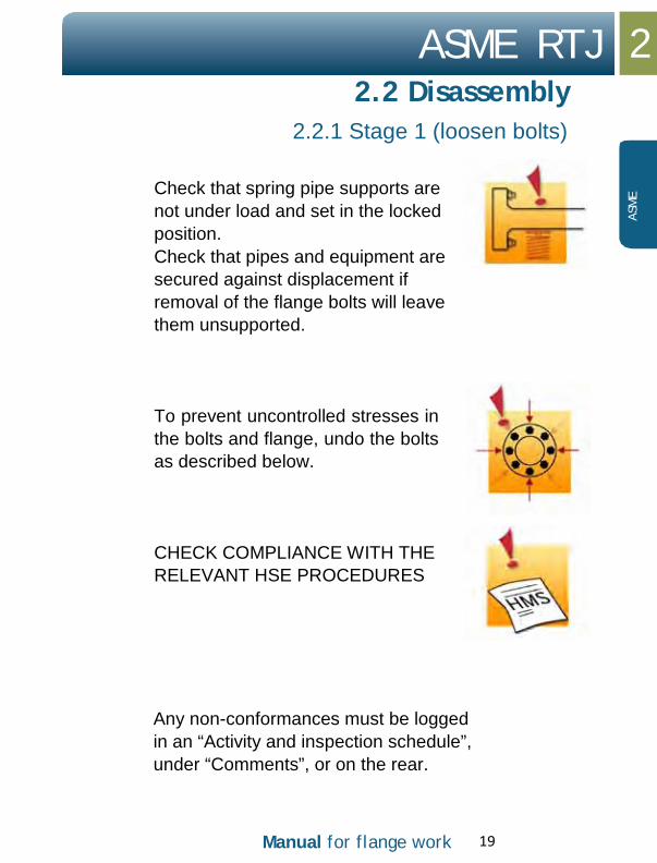
Check that spring pipe supports are not under load and set in the locked position. Check that pipes and equipment are secured against displacement if removal of the flange bolts will leave them unsupported.
To prevent uncontrolled stresses in the bolts and flange, undo the bolts as described below.
CHECK COMPLIANCE WITH THE RELEVANT HSE PROCEDURES
Any non-conformances must be logged in an “Activity and inspection schedule”, under “Comments”, or on the rear.

20 Manual for flange work
2 ASME RTJ
2.2 Disassembly
ASME
2.2.1 Stage 1 (loosen bolts)
1. Use the max. pump pressure for hydraulic tensioners.
2. It is recommended that four tools be used for disassembly.*
*For disassembly with a hydraulic tensioner: see Appendix – Use of tools, Hydraulic
tensioner

Manual for flange work 21
ASME RTJ 2
2.2 Disassembly
2.2.1 Stage 1 (loosen bolts)
ASM
E
3. Ensure the tool is properly counter-held. The counter-hold spanners must be positioned on the same bolts as the tensioners. The counter-hold spanners must prevent the nuts rotating during disassembly.
4. Loosen by a 1/2 turn at a time, and otherwise
follow the procedure for cross-tensioning, until the pretension is taken up by the bolts.
5. Loosen the bolts until there are a few
millimetres of play between the nut and flange. Carefully tap the flange with a suitable hammer to loosen the gasket.

22 Manual for flange work
2 ASME RTJ
2.2 Disassembly
ASME
2.2.2 Stage 2 (open flange)
WARNING: During flange disassembly, it is important to remember the following:
• If one or more bolts get caught in the bolt holes of the flange, this may be a sign of stresses in the pipe system. In such a case, great care must be taken in further disassembly of the flange, and possible securing of pipes must be considered.
• Contact the technical supervisor in the event of doubt or the need for action.
WARNING: When using a hydraulic spreader, it is important to remember the following:
• Never insert your fingers between the
flanges before the safety blocks have been installed and the spreader has been depressurised.
• Use the handle on the spreaders when the tool is to be removed or moved.

Manual for flange work 23
ASME RTJ 2
2.2 Disassembly
ASM
E
2.2.2 Stage 2 (open flange)
1. For safety reasons, not all bolts may be removed before the flange is opened.
2. Use two spreaders, hydraulic or mechanical, crosswise from each other. This results in even opening of the flange.
3. It is important that the
wedges in the spreaders make full contact with both flange faces before being pressurised.
4. When using hydraulic
spreaders, once the desired opening has been achieved, insert safety blocks. The flange will then rest on the safety blocks.
5. Retain the bottom bolts to prevent the seal ring
falling out.
6. Then remove the seal ring using a suitable tool.
Take care not to damage the gasket outline or flange.

24 Manual for flange work
2 ASME RTJ
ASME
2.3 Inspection
Once the flanges have been disassembled and cleaned, the sealing faces must be inspected. Inspection personnel may need to be summoned to perform an internal visual inspection of pipes/equipment and measurement of the ring groove.

Manual for flange work 25
ASME RTJ 2
2.3 Inspection
ASM
E
Any damage must be reported to the technical supervisor. Any stress in the pipe system must also be reported to the technical supervisor. Check bolts and nuts for damage, and clean the threads. Galvanised bolts should normally not be reused.
1. Surface roughness on the facings in the ring groove
must be visually checked against the Ra standard (must have reference template for roughness measurement).
2. Surface roughness must not exceed 1.6
micrometres (µm).
If the flanges are not to be assembled immediately, the gasket faces must be protected.
For more information about inspection and repair of flanges, see API 574 and ASME PCC-2-2011 Article 3.5.

26 Manual for flange work
2 ASME RTJ
ASME
2.4 Alignment
2.4.1 Skewed connection
Any tension in the pipe system that will require greater force to achieve parallel connection of the flanges than in the procedure described below must be approved by the technical supervisor for assessment of risk and possible corrective action.
See ASME PCC-1-2010 Appendix E for guidance on alignment of flanges.
Permitted factory tolerances may result in the flange faces not being equidistant around the entire flange connection; this means the flange faces are not parallel on assembly. In such cases, the bolts must be re-torqued in the area where the gap between the flange faces is greatest.

Manual for flange work 27
ASME RTJ 2
ASM
E
2.4 Alignment
2.4.1 Skewed connection
1. Measure with vernier calipers and identify where the flanges have the greatest gap.
2. Insert all the bolts in the flange connection.
3. When aligning flanged connections, no more than half of the bolts in the flange connection may be used, and no adjoining bolts. This means that there will always be one unused bolt between bolts used for the alignment.
4. Tighten every alternate bolt where the gap
between the flange faces is greatest to 40% of the specified torque for a torque wrench, or 40% of the B pressure for a tensioner. Use the lowest possible number of bolts to align the flanges.
5. Use vernier calipers to measure around the
entire flange connection several times during the process, until the flanges are parallel.

28 Manual for flange work
2 ASME RTJ
2.4 Alignment
2.4.2 Parallel
ASME
Flanges that are out of parallel must always be aligned before tightening can start.
1. Use an available alignment tool. 2. Exact positioning of the aligner depends on your
assessment and the space around the flange. 3. After initial alignment, fit all bolts that can
move freely into the flange’s bolt holes. If they do not all move freely, the aligner must be moved and the flange adjusted until they all do.
4. Lock the flange connection in position once the flanges are parallel. This is done by tightening all the bolts.
Warning:
• Never try to align the flange connection using the bolts alone.
• Always use the alignment tool available. • If you cannot manage to draw the flange
faces parallel, you must contact your line manager.

Manual for flange work 29
ASME RTJ 2
2.5 Assembly
ASM
E
Before tightening flanges, it is important that you perform thorough preparation in planning the job.
1. Check the flange and sealing face for damage, corrosion and wear, and ensure the ring groove is free of paint or preservation coating. There must be no paint on the flange faces on any side of the ring groove.
2. The flange’s mating face with the nuts must also be free of thick coats of paint or preservation coating which could result in the bolts losing pretensioning after assembly. Only primer paint is acceptable under the mating face of the nuts.
3. Clean the sealing face. A steel brush or
approved abrasive paper may be used. Use an approved solvent and cloth rags for final cleaning.
4. Clean along the ring groove. Make sure the
cleaning does not result in radial grooves in the sealing faces. It is particularly important to get rid of any damage in a radial direction.

30 Manual for flange work
2 ASME RTJ
2.5 Assembly
ASME
2.5.1 Seal ring
For ASME RTJ, oval or octagonal metal rings can be used. The type of ring to be used is specified in the torque table/pipe specification.
1. The gap between the flanges must be greater
than the thickness of the seal ring to prevent damage to the latter on assembly.
2. A new seal ring must always be inserted when re-torquing flanges that have been opened.
3. Check you have the right seal ring based on the table, and that it is not damaged. The size and material grade of the ring is marked on it.
4. Rings with absent or incorrect marking must not be used.
5. Insert the bottom bolts in the flange connection to prevent the seal ring falling down.
6. Check the ring sits correctly. It must be able to “rock” in the ring groove.
Metal rings (RTJ) must be lubricated before insertion using a thin film of acid-free Vaseline or thin machine oil. This is to prevent stress spots, and it will be easier to disassemble/remove the gasket again. Gaskets that are PTFE-coated must not be lubricated. No grease or similar may be used in the ring groove, as this may prevent the ring from achieving a full seal.
Manual for flange work 31
ASME RTJ 2
2.5 Assembly
2.5.2 Bolts
ASM
E
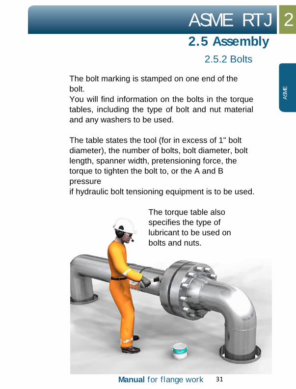
The bolt marking is stamped on one end of the bolt. You will find information on the bolts in the torque tables, including the type of bolt and nut material and any washers to be used.
The table states the tool (for in excess of 1" bolt diameter), the number of bolts, bolt diameter, bolt length, spanner width, pretensioning force, the torque to tighten the bolt to, or the A and B pressure if hydraulic bolt tensioning equipment is to be used.
The torque table also specifies the type of lubricant to be used on bolts and nuts.
32 Manual for flange work
2 ASME RTJ
2.5 Assembly
ASME
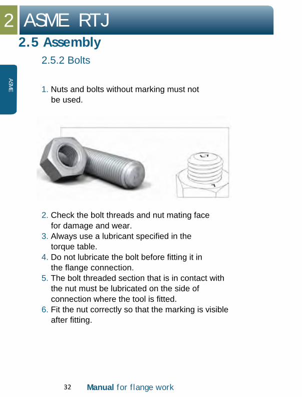
2.5.2 Bolts
1. Nuts and bolts without marking must not be used.
2. Check the bolt threads and nut mating face for damage and wear.
3. Always use a lubricant specified in the torque table.
4. Do not lubricate the bolt before fitting it in the flange connection.
5. The bolt threaded section that is in contact with the nut must be lubricated on the side of connection where the tool is fitted.
6. Fit the nut correctly so that the marking is visible after fitting.

Manual for flange work 33
ASME RTJ 2
2.5 Assembly
2.5.2 Bolts
ASM
E
7. The nut the tensioner is fitted to must be lubricated on its mating face with the flange, as well as the first two turns from the flange.
8. The bolts must move freely through the opposite flange.
The friction in a bolted joint is difficult to accurately predict, as it is dependent on a wide range of variables. Given that most of the torque is involved in overcoming friction, it is important that the bolt and the nut’s thread are checked and lubricated.

34 Manual for flange work
2 ASME RTJ
2.5 Assembly
ASME
2.5.3 Tightening
Only use an approved tool that has been specified in the torque table. If another tool must be used, a new and approved torque table must be drawn up.
If it is necessary to make a special tool to ensure access for tightening in confined areas, this must be approved in accordance with the procedures in the operating company.
Before the tool is taken into service, the following must be checked:
1. Calibration of the tool is valid. 2. The tool and equipment are in safe condition
prior to being pressurised. 3. Use of the tool and equipment is in accordance
with the supplier’s instructions for use.

Manual for flange work 35
ASME RTJ 2
2.5 Assembly
2.5.3 Tightening
ASM
E
The following safety measures must be implemented once the tool is in use:
1. Keep a safe distance from the tool while it is
pressurised. 2. Do not hold on to, or attempt to adjust the tool
when it is in operation. 3. Never leave the work place with the tool
pressurised. 4. Use a safety line on loose tools when working at
height.
See Appendix “Safety aspects”.
See various tightening procedures in “Appendix”.

2 ASME RTJ
2.6 Follow-up
36 Manual for flange work
ASME
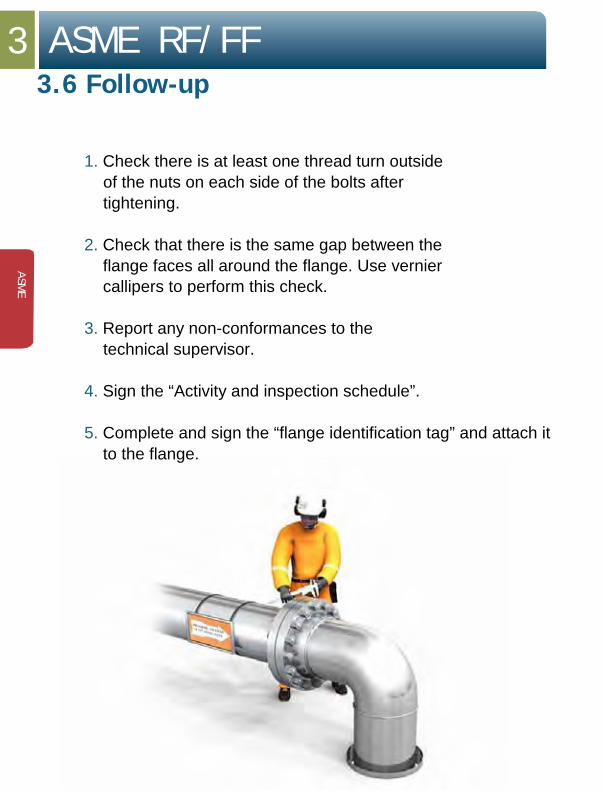
1. Check there is at least one thread turn outside of the nuts on each side of the bolts after tightening.
2. Check that there is the same gap between the
flange faces all around the flange. Use vernier calipers to perform this check.
3. Report any non-conformances to the
technical supervisor.
4. Sign the “Activity and inspection schedule”.
5. Complete and sign the “flange identification tag” and attach it to the flange.

ASME RTJ 2
Manual for flange work 37
ASM
E
2.6 Follow-up inspections
The supervisor for the assembly must complete and sign an “Activity and inspection schedule”, as and when the flanges are assembled and the bolt connections have been tightened to the specified torque/tensile force.
6. Any old marking on the flanges must be removed, and a new tag must be attached to the flange connection.
If, during assembly forces additional to those specified in the chapter “Alignment” are required to align the flange before the normal tightening procedure can begin, this must be indicated in the comments field in the “Activity and inspection schedule” by the specialist performing the work. This applies to all types of flange and clamp connections. The non-conformance must be recorded in the company’s system for non-conformance management.
7. If different people have been responsible for assembly and final bolt torque-up, both must have signed, with the date the job was completed.

2 ASME RTJ
2.6 Follow-up
38 Manual for flange work
ASME
Exception:
For non-hazardous auxiliary/support liquids and gases, the “Activity and inspection schedule” and tagging of the flange connections may be omitted for ASME pressure classes 150 and 300 where the operating temperature is between 0◦ and 50◦C.
1. If the equipment is brought into commission immediately (with the specialist performing the work and the operator present), tagging of the flange connections and use of the “Activity and inspection schedule” may be omitted.
2. In the event of any type of non-conformance,
this must be recorded in the company’s system for non-conformance management.

ASME RTJ 2
Manual for flange work 39
ASM
E

2 ASME RTJ
2.6 Follow-up
40 Manual for flange work
ASME RF/FF 3
3.1 Flange and gasket 42 - 44
3.2 Disassembly 44 - 49
3.3 Inspection 50 - 51
3.4 Alignment 52 - 53
3.5 Assembly 54 - 61
3.6 Follow-up inspections 62 - 65

3 ASME RF/FF
3.1 Flange and gasket
42 Manual for flange work
ASME
ASME Raised Face seals by installing a flat gasket between the raised faces of the flanges to be joined. The gaskets may be of graphite laminate, glass fibre (CGF), or spiral gasket type. Use the gasket specified in the torque table.

ASME RF/FF 3
3.1 Flange and gasket
Manual for flange work 43
ASM
E
On tightening, the gasket is compressed and pressed down into a small groove in the flange’s mating face. These grooves are circular and form part of the flange structure to provide the best possible seal. The grooves cover the entire mating face. The gaskets become permanently deformed and must therefore not be reused.

3 ASME RF/FF
3.1 Flange and gasket
44 Manual for flange work
ASME
Flanges of ASME RF and ASME FF type can occur in the following designs:
Weld-neck
Slip-on
Screwed
Socket-weld
Lapped
Blind

Manual for flange work 45
ASME RF/FF 3
3.2 Disassembly
ASM
E
3.2.1 Stage 1 (loosen bolts)
Check that the safety clearance is in accordance with the work description. Am I working on the right flange?
Check that spring pipe supports are not under load and set in the locked position.
On disassembly, never assume that the line is not under pressure. All flanges should be disassembled as if the system were pressurised. Pressure build-up can occur due to several causes.
To prevent uncontrolled stresses in the bolts and flange, undo the bolts as described below.
CHECK COMPLIANCE WITH THE RELEVANT HSE PROCEDURES
Any non-conformances must be logged in the “Activity and inspection schedule”, under “Comments”, or on the rear.

46 Manual for flange work
3 ASME RF/FF
3.2 Disassembly
ASME
3.2.1 Stage 1 (loosen bolts)
1. Use the max. pump pressure for hydraulic tensioners. 2. It is recommended that four tools be used
for disassembly.* 3. Ensure the tool is properly counter-held.
The counter-hold spanners must be positioned on the same bolts as the tensioners. The counter-hold spanners must prevent the nuts rotating during disassembly.
4. Loosen by a 1/2 turn at a time, and otherwise follow the procedure for cross-tensioning, until the pretension is taken up by the bolts.
5. Loosen the bolts until there are a few millimetres of play between the nut and flange. Carefully tap the flange with a suitable hammer to loosen the gasket.
*For disassembly with a hydraulic tensioner: see Appendix – Use of tools, Hydraulic
tensioner

Manual for flange work 47
ASME RF/FF 3
3.2 Disassembly
ASM
E
3.2.2 Stage 2 (open flange)
WARNING: During flange disassembly, it is important to remember the following:
If one or more bolts get caught in the bolt holes of the flange, this may be a sign of tension in the pipe system. In such a case, great care must be taken in further disassembly of the flange, and possible securing of pipes must be considered. Contact the technical supervisor in the event of doubt or the need for action.
1. For safety reasons, not all bolts may be
removed before the flange is opened. 2. Use two spreaders, hydraulic or mechanical,
crosswise from each other. This results in even opening of the flange.
3. It is important that the wedges in the spreaders make full contact with both flange faces before being pressurised.
4. When using hydraulic spreaders, once the desired opening has been achieved, insert safety blocks. The flange will then rest on the safety blocks.
5. Retain the lowest bolts to prevent the gasket falling out.
6. Then remove the gasket using a suitable tool. Take care not to damage the mating face.

48 Manual for flange work
3 ASME RF/FF
3.2 Disassembly
ASME
3.2.2 Stage 2 (open flange)
WARNING when using a hydraulic spreader:
• Never insert your fingers between the
flanges before the safety blocks have been installed and the spreaders have been depressurised.
• Use the handle on the spreaders when the tool is to be removed or moved.
*For disassembly with a hydraulic tensioner: see Appendix – Use of tools, Hydraulic tensioner

Manual for flange work 49
ASME RF/FF 3
3.3 Inspection
ASM
E
Once the flanges have been disassembled, the sealing faces must be cleaned and checked for damage. Inspection personnel may need to be summoned to perform an internal visual inspection of pipes/equipment. Any damage must be reported to the technical supervisor. Any stress in the pipe system must be reported to the technical supervisor. Check bolts and nuts for damage, and clean the threads. Galvanised bolts should normally not be reused.
• Surface roughness on the sealing faces
must be visually checked against the Ra standard (must have reference template for roughness measurement). Surface roughness must not exceed 6.3 micrometres (µm) for pressurised systems (3.2 micrometres (µm) for vacuum service).
For more information about inspection and repair of flanges, see API 574 and ASME PCC-2-2011 Article 3.5.

50 Manual for flange work
3 ASME RF/FF
ASME
3.3 Inspection
* For more information on troubleshooting in the event of leaks from flanges, see Appendix “Checklist for leaking flanges”.
If the flanges are not to be assembled immediately, the gasket faces must be protected.
Manual for flange work 51
ASME RF/FF 3
3.4 Alignment
3.4.1 Skewed connection
ASM
E
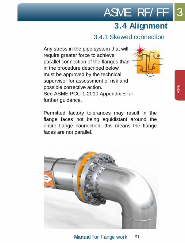
Any stress in the pipe system that will require greater force to achieve parallel connection of the flanges than in the procedure described below must be approved by the technical supervisor for assessment of risk and possible corrective action. See ASME PCC-1-2010 Appendix E for further guidance.
Permitted factory tolerances may result in the flange faces not being equidistant around the entire flange connection; this means the flange faces are not parallel.

52 Manual for flange work
3 ASME RF/FF
ASME
3.4 Alignment
3.4.1 Skewed connection
In such cases, the bolts must be re-torqued in the area where the gap between the flange faces is greatest.
1. Measure with vernier calipers and identify where the flanges have the greatest gap.
2. Insert all the bolts in the flange connection.
3. When aligning flanged connections, no more than half of the bolts in the flange connection may be used, and no adjoining bolts. This means that there will always be one unused bolt between bolts used for the alignment.
4. Tighten every alternate bolt where the gap
between the flange faces is greatest to 40% of the specified torque for a torque wrench, or 40% of the B pressure for a tensioner. Use the lowest possible number of bolts to align the flanges.
5. Use vernier calipers to measure around the entire flange connection several times during the process until the flanges are parallel.

Manual for flange work 53
ASME RF/FF 3
3.4 Alignment
3.4.2 Parallel displacement
ASM
E
Flanges that are out of parallel must always be aligned before tightening can start.
1. Use an available alignment tool.
2. Exact positioning of the aligner depends on your assessment and the space around the flange.
3. After initial alignment, fit all bolts that can move freely into the flange’s bolt holes. If they do not all move freely, the aligner must be moved and the flange adjusted until they all do.
4. Lock the flange connection in position once the flanges
are parallel. This is done by tightening all the bolts.
Warning:
• Never try to align the flange connection using the bolts alone.
• Always use the alignment tool available. • If you cannot manage to draw the flange
faces parallel, you must contact your line manager.

54 Manual for flange work
3 ASME RF/FF
3.5 Assembly
ASME
Before tightening flanges, it is important that you perform thorough preparation in planning the job.
1. Check the flange and sealing face for damage, corrosion and wear, and ensure the sealing face is free of paint or preservation coating.
2. The flange’s mating face with the nuts must also
be free of thick coats of paint or preservation coating which could result in the bolts losing pretensioning after assembly. Only primer paint is acceptable under the nut face that makes contact with the flange.
3. Clean the sealing face. A steel brush or
approved abrasive paper may be used. Use an approved solvent and cloth rags for final cleaning.
4. Clean along the small grooves in the gasket
face. Make sure the cleaning does not result in radial grooves in the sealing face. It is particularly important to get rid of any damage in a radial direction. See ASME PCC-2-2011 Appendix D for acceptance limits for flatness and damage to the gasket faces.

Manual for flange work 55
ASME RF/FF 3
3.5 Assembly
3.5.1 Gasket
ASM
E
For ASME RF/FF, flat gaskets or spiral gaskets must normally be used. The type of gasket to be used is specified in a torque table.
1. The gap between the flanges must be greater than the thickness of the gasket to prevent damage to the latter on assembly.
2. A new gasket must always be inserted when
re-torquing flanges that have been opened.
3. Check you have the right gasket based on the torque table, and that it is not damaged.
4. NB! In some cases, especially where pipe wall
thickness is small, a gasket with an ASME standard inner diameter will result in the diameter being too small, making the gasket project into the pipe. This is to be avoided by selecting a gasket of the correct inner diameter.

56 Manual for flange work
3 ASME RF/FF
3.5 Assembly
ASME
3.5.1 Gasket
1. Insert the bottom bolts in the flange so that the gasket does not fall down. On larger flanges the gasket is often soft and difficult to position, and it can easily fall down into the pipe. Take special care, therefore, when assembling gaskets to flanges that are fitted in a horizontal position.
2. Check the gasket sits correctly. It is a good
idea to use a torch to verify the gasket will lie against the bolts all around the flange. This is a good indication that the gasket is of the right outer diameter. The bolts will centre the gasket so that it lies correctly against the mating face.

Manual for flange work 57
ASME RF/FF 3
3.5 Assembly
3.5.2 Bolts
ASM
E
The bolt marking is stamped on one end of the bolt. You will find information on the bolts in the torque table, including the type of bolt and nut material to be used. The table also states the tool (for in excess of 1" bolt diameter), the number of bolts, bolt diameter, bolt length, spanner width, pretensioning force and the torque to tighten the bolt to, or the A and B pressure if hydraulic bolt tensioning equipment is to be used. The torque table also specifies the type of lubricant to be used on bolts and nuts.

58 Manual for flange work
3 ASME RF/FF
3.5 Assembly
ASME
3.5.2 Bolts
1. Nuts and bolts without marking must not be used.
2. Check the bolt threads and nut mating face
for damage and wear.
3. Always use a lubricant specified in the torque table.
4. Do not lubricate the bolt before fitting it in
flange connections.
5. The bolt threaded section that is in contact with the nut must be lubricated on the side of the connection where the tool is fitted.
6. Fit the nut correctly so that the marking is visible
after fitting.

Manual for flange work 59
ASME RF/FF 3
3.5 Assembly
3.5.2 Bolts
ASM
E
7. The nut the tensioner is fitted to must be
lubricated on its mating face with the flange, as well as the first two turns in the direction of the flange.
8. The bolts must move freely through the opposite flange.
The friction in a bolted joint is difficult to accurately predict, as it is dependent on a wide range of variables. Given that most of the torque is involved in overcoming friction, it is important that the bolt and the nut’s thread are checked and lubricated.

60 Manual for flange work
3 ASME RF/FF
3.5 Assembly
ASME
3.5.3 Tightening
Only use an approved tool that has been specified in the torque table. If another tool must be used, a new and approved torque table must be drawn up.
If it is necessary to make a special tool to ensure access for tightening in confined areas, this must be approved in accordance with the procedures in the operating company.
Before the tool is taken into service, the following must be checked:
1. Calibration of the tool is valid. 2. The tool and equipment are in safe condition
prior to being pressurised. 3. Use of the tool and equipment is in accordance
with the supplier’s instructions for use.

Manual for flange work 61
ASME RF/FF 3
3.5 Assembly
3.5.3 Tightening
ASM
E
The following safety measures must be implemented once the tool is in use:
1. Keep a safe distance from the tool while it is
pressurised. 2. Do not hold on to, or attempt to adjust the tool
when it is in operation. 3. Never leave the work place with the tool
pressurised. 4. Use a safety line on loose tools
when working at height.
See Appendix “Safety aspects”.
See various tightening procedures in “Appendix”.
3 ASME RF/FF
3.6 Follow-up
62 Manual for flange work
ASME
1. Check there is at least one thread turn outside of the nuts on each side of the bolts after tightening.
2. Check that there is the same gap between the
flange faces all around the flange. Use vernier callipers to perform this check.
3. Report any non-conformances to the
technical supervisor.
4. Sign the “Activity and inspection schedule”.
5. Complete and sign the “flange identification tag” and attach it to the flange.

ASME RF/FF 3
Manual for flange work 63
ASM
E
3.6 Follow-up inspections
The supervisor for the assembly must complete and sign an “Activity and inspection schedule”, as and when the flanges are assembled and the bolt connections have been tightened to the specified torque/tensile force.
6. Any old marking on the
flanges must be removed, and a new tag must be attched to the flange connection.
If, during assembly forces that go beyond those specified in the chapter “Alignment” are required to align the flange before the normal tightening procedure can begin, this must be indicated in the comments field in the “Activity and inspection schedule” by the specialist performing the work. This applies to all types of flange and clamp connections. The non-conformance must be recorded in the company’s system for non-conformance management.
7. If different people have been responsible for
assembly and final bolt torque-up, both must have signed, with the date the job was completed.

3 ASME RF/FF
3.6 Follow-up
64 Manual for flange work
ASME
Exception:
For non-hazardous auxiliary/support liquids and gases, the “Activity and inspection schedule” and tagging of the flange connections may be omitted for ASME pressure classes 150 and 300 where the operating temperature is between 0◦ and 50◦C.
1. If the equipment is brought into commission immediately (with the specialist performing the work and the operator present), tagging of the flange connections and use of the “Activity and inspection schedule” may be omitted.
2. In the event of any type of non-conformance,
this must be recorded in the company’s system for non-conformance management.

ASME RF/FF 3
Manual for flange work 65
ASM
E

3 ASME RF/FF
3.6 Follow-up
66 Manual for flange work
API 6A type 6B/BX 4
4.1 Flange and gasket type 6B 68 - 69
4.1 Flange and gasket type BX 70 - 71
4.2 Disassembly 72 - 76
4.3 Inspection 77 - 79
4.4 Alignment 80 - 82
4.5 Assembly 83 - 87
4.6 Tightening 88 - 89
4.7 Follow-up inspections 90 - 91

4 API 6A type 6B/BX
4.1 Flange and gasket type 6B
68 Manual for flange work
API 6A type
API 6A type 6B is used from API pressure class 2000 PSI up to 5000 PSI. The ring groove is designed to take seal rings of type R (oval, octagonal) or RX. Always use the ring type specified in the torque table.
All gasket rings must have the following minimum marking on the outside: manufacturer name or identification, ring type (R, RX or BX) and material identification. Rings lacking the requisite identification must not be used.
On tightening, the ring undergoes plastic deformation in the mating faces with the ring groove, resulting in a metal-to-metal seal. The seal of an RX-ring is primarily with the outer edge of the ring groove. As the deformation is permanent, the seal ring cannot be reused.
After tightening, API 6A type 6B flanges are designed to leave a gap between the flanges inside at the ring, once the bolts have reached the specified pretension. Flanges of this type may be both Raised Face and Flat Face.


4 API 6A type 6B/BX
4.1 Flange and gasket type BX
70 Manual for flange work
API 6A type
API 6A type 6BX is used from API pressure class 5000 PSI up to 20000 PSI. The ring groove is designed to take seal rings of type BX only. The BX ring always has a hole for pressure equalisation.
On tightening, the ring undergoes plastic deformation in its mating faces with the ring groove, resulting in a metal-to-metal seal which seals both inner and outer diameter. As the deformation is permanent, the seal ring cannot be reused.
After tightening API 6A type 6BX flanges, the flange faces inside at the ring must come together completely or almost completely (almost negligible gap).


4 API 6A type 6B/BX
4.2 Disassembly
4.2.1 Stage 1 (loosen bolts)
72 Manual for flange work
API 6A type
Check that the safety clearance is in accordance with the work description. Am I working on the right flange?
Check for stresses in the pipe system.
On disassembly, never assume that the line is not under pressure. All flanges should be disassembled as if the system were pressurised. Pressure build-up can occur due to several causes.
To prevent uncontrolled stresses in the bolts and flange, undo the bolts as described below.

API 6A type 6B/BX 4
4.2 Disassembly
4.2.2 Stage 1 (loosen bolts)
Manual for flange work 73
API 6
A ty
pe
CHECK COMPLIANCE WITH THE RELEVANT HSE PROCEDURES.
Any non-conformances must be logged in an “Activity and checking schedule”, under “Comments”, or on the rear.

4 API 6A type 6B/BX
4.2 Disassembly
4.2.1 Stage 1 (loosen bolts)
74 Manual for flange work
API 6A type
1. Use the max. pump pressure for hydraulic tensioners.
2. It is recommended that four tools be used
for disassembly. *
*For disassembly with a hydraulic tensioner: see Appendix – “Use of tools, Hydraulic
tensioner”

Manual for flange work 75
API 6A type 6B/BX 4
4.2 Disassembly
4.2.1 Stage 1 (loosen bolts)
API 6
A ty
pe
3. Ensure the tool is properly counter-held. The counter-hold spanners must be positioned on the same bolts as the tensioners. The counter-hold spanners must prevent the nuts rotating during disassembly.
4. Loosen by a 1/2 turn at a time, and
otherwise follow the procedure for cross-tensioning, until the pretension is taken up by the bolts.
5. Loosen the bolts until there are a few
millimetres of play between the nut and flange. Carefully tap the flange with a suitable hammer to loosen the gasket.

76 Manual for flange work
4 API 6A type 6B/BX
4.3 Disassembly
4.3.1 Stage 2 (open
API 6A type
WARNING: During flange disassembly, it is important to remember the following:
• If one or more bolts get caught in the bolt holes of the flange, this may be a sign of stresses in the pipe system. In such a case, great care must be taken in further disassembly of the flange, and possible securing of pipes must be considered.
WARNING: When using a hydraulic spreader, it is important to remember the following:
• Never insert your fingers between the
flanges before the safety blocks have been installed and the spreaders have been depressurised.
• Use the handle on the spreaders when the tool is to be removed or moved.

Manual for flange work 77
API 6A type 6B/BX 4
4.4 Inspection
4.4.1 Stage 2 (open
API 6
A ty
pe
1. For safety reasons, not all bolts may be
removed before the flange is opened.
2. Use two spreaders, hydraulic or mechanical, crosswise from each other. This results in even opening of the flange.
3. It is important that the
wedges in the spreaders make full contact with both flange faces before being pressurised.
4. When using hydraulic
spreaders, once the desired opening has been achieved, insert safety blocks. The flanges will then rest on the safety blocks.
5. Retain the bottom bolts to prevent the seal
ring falling out.
6. Then remove the seal ring using a suitable tool.
Take care not to damage the gasket outline or flange.

78 Manual for flange work
4 API 6A type 6B/BX
API 6A type
4.4 Inspection
Once the flanges have been disassembled and cleaned, they must be inspected. Inspection personnel may need to be summoned to perform an internal visual inspection of pipes/equipment and measurement of the ring groove.
Any damage must be reported to the technical supervisor. Any stress in the pipe system must also be reported to the technical supervisor. Check bolts and nuts for damage, and clean the threads. Galvanised bolts should normally not be reused.
1. Surface roughness on the facings in the ring groove
must be visually checked against the Ra standard (must have reference template for roughness measurement).
2. Type 6B: Surface roughness must not exceed
Ra equal to or less than 1.6 micrometres (µm).
3. Type 6BX: Surface roughness must not exceed Ra equal to or less than 0.8 micrometres
(µm).

Manual for flange work 79
API 6A type 6B/BX 4
4.4 Inspection
4.4.1 Inspection – troubleshooting
API 6
A ty
pe
For more information on troubleshooting in the event of leaks from flanges, see Appendix – “Checklist for leaking flanges”.
If the flanges are not to be assembled immediately, the gasket faces must be protected.
For more information about inspection and repair of flanges, see API 574 and ASME PCC-2-2011 Article 3.5.

80 Manual for flange work
4 API 6A type 6B/BX
4.5 Alignment
API 6A type
4.5.1 Skewed connection
Any stress in the pipe system that will require greater force to achieve parallel connection of the flanges than in the procedure described below must be approved by the technical supervisor for assessment of risk and possible corrective action.
Permitted factory tolerances may result in the flange faces not being equidistant around the entire flange connection; this means the flange faces are not parallel.
1. Measure with vernier calipers and identify where the flanges
have the greatest gap.
2. Insert all the bolts in the flange connection.
3. When aligning flanged connections, no more than half of the bolts in the flange connection may be used, and no adjoining bolts. This means that there will always be one unused bolt between bolts used for the alignment. See ASME PCC-1-2010 Appendix E for more guidance on alignment

Manual for flange work 81
API 6A type 6B/BX 4
4.5 Alignment
4.5.1 Skewed
API 6
A ty
pe
4. Tighten every alternate bolt where the gap
between the flange faces is greatest to 40% of the specified torque for a torque wrench, or 40% of the B pressure for a tensioner. Use the lowest possible number of bolts to draw the flanges together.
5. Use vernier calipers to measure around the entire flange connection several times during the process, until the flanges are parallel.

82 Manual for flange work
4 API 6A type 6B/BX
4.5 Alignment
API 6A type
4.5.2 Parallel displacement
Flanges that are out of parallel must always be aligned before tightening can start.
1. Use an available alignment tool.
2. Exact positioning of the aligner depends on your assessment and the space around the flange.
3. After initial alignment, fit all bolts that can move freely into the flange’s bolt holes. If they do not all move freely, the aligner must be moved and the flange adjusted until they all do.
4. Lock the flange connection in position
once the flanges are parallel. This is done by tightening all the bolts.
Warning:
• Never try to align the flange connection using the bolts alone.
• Always use the alignment tool available. • If you cannot manage to draw the flange
faces parallel, you must contact your line manager.

Manual for flange work 83
API 6A type 6B/BX 4
4.6 Assembly
API 6
A ty
pe
Before tightening flanges, it is important that you perform thorough preparation in planning the job.
1. Check the flange and sealing face for
damage, corrosion and wear, and ensure the sealing face is free of paint or preservation coatings.
2. The flange’s mating face with the nuts
must also be free of thick layers of paint or preservation coating which could result in the bolts losing pretension after assembly. Only primer paint is acceptable under nuts.
3. Clean the sealing face. A steel brush or
approved abrasive paper may be used. Use an approved solvent and cloth rags for final cleaning.
4. Clean along the ring groove. Make sure the
cleaning does not result in radial grooves in the ring groove. It is particularly important to get rid of any damage in a radial direction.

84 Manual for flange work
4 API 6A type 6B/BX
4.6 Assembly
API 6A type
4.6.1 Seal ring
For API 6A type 6B flanges, R and RX metal rings may be used. For API 6A type 6BX, BX metal rings must be used. The type of ring to be used is specified in the torque table/pipe specification.
1. The gap between the flanges must be greater
than the thickness of the seal ring to prevent damage to the latter on assembly.
2. A new seal ring must always be inserted when
re-torquing flanges that have been opened.
3. Check you have the right seal ring based on the torque table and that it is not damaged. All gasket rings must have the following minimum marking on the outside: manufacturer name or identification, ring type (R, RX or BX) and material identification.
4. Rings with absent or incorrect marking
must not be used.
5. Insert the bottom bolts in the flange
connection so that the seal ring does not fall down.

Manual for flange work 85
API 6A type 6B/BX 4
4.6 Assembly
4.6.1 Seal ring
API 6
A ty
pe
Check the ring sits correctly. It must be able to “rock” in the ring groove.
Metal rings (RTJ) must be lubricated before insertion using a thin film of acid-free Vaseline or thin machine oil. This is to prevent stress spots, and it will be easier to disassemble/remove the gasket again. Gaskets that are PTFE-coated must not be lubricated. No grease or similar may be used in the ring groove, as this may prevent the ring from achieving a full seal.

86 Manual for flange work
4 API 6A type 6B/BX
4.6 Assembly
API 6A type
4.6.2 Bolts
The bolt marking is stamped on one end. You will find information on the bolts in the torque table, including the type of bolt and nut material to be used.
The table states the tool (for in excess of 1" bolt diameter), the number of bolts, bolt diameter, bolt length, spanner width, pretensioning force, the torque to tighten the bolt to, or the A and B pressure if hydraulic bolt tensioning equipment is to be used. The torque table also specifies the type of lubricant to be used on bolts and nuts, as well as any washers.
1. Nuts and bolts without marking must not be used.
2. Check the bolt threads and nut mating face for damage and wear.
3. Always use a lubricant specified in the torque table.

Manual for flange work 87
API 6A type 6B/BX 4
4.6 Assembly
4.6.2 Bolts
API 6
A ty
pe
4. Do not lubricate the bolt before fitting it in
the flange connection.
5. The bolt threaded section that is in contact with the nut must be lubricated on the side of the flange connection where the tool is fitted.
6. Fit the nut correctly so that the marking is visible after fitting.
7. The nut the tensioner is fitted to must be
lubricated on its mating face with the flange, as well as the first two turns in the direction of the flange.
8. The bolts must move freely through the opposite flange.
The friction in a bolted joint is difficult to accurately predict, as it is dependent on a wide range of variables. Given that most of the torque is involved in overcoming friction, it is important that the bolt and the nut’s thread are checked and lubricated.

88 Manual for flange work
4 API 6A type 6B/BX
4.7 Tightening
API 6A type
Only use an approved tool that has been specified in the torque table. If another tool must be used, a new and approved torque table must be drawn up.
If it is necessary to make a special tool to ensure access for tightening in confined areas, this must be approved in accordance with the procedures in the operating company.
Before the tool is taken into service, the following must be checked:
1. Calibration of the tool is valid.
2. The tool and equipment are in safe condition prior to being pressurised.
3. Use of the tool and equipment is in accordance
with the supplier’s instructions for use.

Manual for flange work 89
API 6A type 6B/BX 4
4.7 Tightening
API 6
A ty
pe
The following safety measures must be implemented once the tool is in use:
1. Keep a safe distance from the tool while it is
pressurised.
2. Do not hold on to, or attempt to adjust the tool
when it is in operation.
3. Never leave the work place with the tool
pressurised.
4. Use a safety line on loose tools when
working at height.
See also Appendix – “Safety aspects”.
See various tightening procedures in “Appendix”.

90 Manual for flange work
4 API 6A type 6B/BX
4.8 Follow-up inspections
API 6A type
1. Check there is at least one thread turn outside of the nuts on each side of the bolts after tightening.
2. Check that there is the same gap between the
flange faces all around the flange. Use vernier calipers to perform this check.
3. Report any non-conformances to the technical supervisor.
4. Sign the “Activity and inspection schedule”.
5. Complete and sign the “flange identification tag” and attach it to the flange.

Manual for flange work 91
API 6A type 6B/BX 4
4.8 Follow-up
API 6
A ty
pe
The supervisor for the assembly must complete and sign an “Activity and inspection schedule”, as and when the flanges are assembled and the bolt connections have been tightened to the specified torque/tensile force.
6. Any old marking on the flanges must be removed, and a new tag must be attached to the flange connection.
If, during assembly, forces additional to those specified in the chapter “Alignment” are required to align the flange before the normal tightening procedure can begin, this must be indicated in the comments field in the “Activity and inspection schedule” by the specialist performing the work. This applies to all types of flange and clamp connections. The non-conformance must be recorded in the company’s system for non-conformance management.
7. If different people have been responsible for
assembly and final bolt torque-up, both must have signed, with the date the job was completed.

92 Manual for flange work
4 API 6A type 6B/BX
4.8 Follow-up inspections
NCF5 Compact 5
5.1 Flange and gasket 94 - 95
5.2 Disassembly 96 - 103
5.3 Inspection 104 - 108
5.4 Alignment 109 - 113
5.5 Assembly 114 - 119
5.6 Tightening 120 - 121
5.7 Follow-up inspections 122 - 123


NCF5 Compact 5
5.1 Flange and gasket
Manual for flange work 95
NCF
5
The seal ring of a compact flange, the IX ring, has a characteristic groove all round its outer edge. All marking is on the inside of the ring. The main seal is made by the ring, which seals around the outer diameter. If this full seal fails, pressure build-up occurs on the inside of the ring. The higher the pressure, the better the seal from the ring.
The metal-to-metal deformation of the seal ring is controlled. The sealing forces between the ring and ring groove are not affected by dynamic forces, as the pretension in the bolts is taken up by the flange faces. This gives a static connection with almost no flange movement – even when significant dynamic forces are applied. This means that the need for bolt re-torquing is eliminated.

96 Manual for flange work
5 NCF5 Compact
5.2 Disassembly
5.2.1 Stage 1 (loosen bolts)
NCF5
Check that the safety clearance is in accordance with the work description. Am I working on the right flange?
Check that spring pipe supports are not under load and set in the locked position.
On disassembly, never assume that the line is not under pressure. All flanges should be disassembled as if the system were pressurised. Pressure build-up can occur due to several causes.

Manual for flange work 97
NCF5 Compact 5
5.2 Disassembly
5.2.1 Stage 1 (loosen bolts)
NCF
5
To prevent uncontrolled stresses in the bolts and flange, undo the bolts as described below.
CHECK COMPLIANCE WITH THE RELEVANT HSE PROCEDURES.
Any non-conformances must be logged in an “Activity and checking schedule”, under “Comments”, or on the rear.

98 Manual for flange work
5 NCF5 Compact
5.2 Disassembly
5.2.1 Stage 1 (loosen bolts)
NCF5
1. Use the max. pump pressure for
hydraulic tensioners.
2. It is recommended that four tools be used
for disassembly. *
*For disassembly with a hydraulic tensioner: see Appendix – “Use of tools, Hydraulic
tensioner”

Manual for flange work 99
NCF5 Compact 5
5.2 Disassembly
5.2.1 Stage 1 (loosen bolts)
NCF
5
3. Ensure the tool is properly counter-held. The counter-hold spanners must be positioned on the same bolts as the tensioners. The counter-hold spanners must prevent the nuts rotating during disassembly.
4. Loosen by a 1/6 turn (60 degrees) at a time, and
otherwise follow the procedure for cross-tensioning, until the pretension is taken up by the bolts.
5. Loosen the bolts until there are a few
millimetres of play between the nut and flange. Carefully tap the flange with a suitable hammer to loosen the gasket.

100 Manual for flange work
5 NCF5 Compact
5.2 Disassembly
5.2.2 Stage 2 (open
NCF5
WARNING: During flange disassembly, it is important to remember the following:
• If one or more bolts get caught in the bolt holes of the flange, this may be a sign of stresses in the pipe system. In such a case, great care must be taken in further disassembly of the flange, and possible securing of pipes must be considered.
WARNING: When using a hydraulic spreader, it is important to remember the following:
• Never insert your fingers between the
flanges before the safety blocks have been installed and the spreaders have been depressurised.
• Use the handle on the spreaders when the tool is to be removed or moved.

Manual for flange work 101
NCF5 Compact 5
5.2 Disassembly
5.2.2 Stage 2 (open flange)
NCF
5
In the case of compact flange disassembly, extra vigilance is needed to prevent damage to the flange sealing faces.
For compact flanges, it is recommended to us flange spreaders that can be fitted to the flange bolt holes.

102 Manual for flange work
5 NCF5 Compact
5.2 Disassembly
5.2.2 Stage 2 (open
NCF5
Use of standard flange spreaders should be avoided, as these may damage the compact flange seal around the outer diameter.
1. For safety reasons, not all bolts may be
undone completely before the flange is opened. Only remove those bolts that need removing to access the flange spreader.
2. Use two spreaders, hydraulic or mechanical, crosswise from each other. This results in even opening of the flange.

Manual for flange work 103
NCF5 Compact 5
5.2 Disassembly
5.2.2 Stage 2 (open flange)
NCF
5
3. It is important that the spreaders fitted in the
flange bolt holes do not make contact with the opposite flange. Use the right dimension of sockets for the diameter of the flange bolt holes.
4. When using hydraulic spreaders, once the desired opening has been achieved, insert safety blocks.
5. Retain the bottom bolts to prevent the seal ring falling out.
6. Then remove the seal ring using a suitable tool. Take care not to damage the ring groove, sealing faces or flange.

104 Manual for flange work
5 NCF5 Compact
NCF5
5.3 Inspection
Once the flanges have been disassembled and cleaned, they must be inspected. Inspection personnel may need to be summoned to perform an internal visual inspection of pipes/equipment and measurement of the ring groove. Any damage must be reported to the technical supervisor. Any stress in the pipe system must be reported to the technical supervisor.
Check bolts and nuts for damage, and clean the threads. Galvanised bolts should normally not be reused.

Manual for flange work 105
NCF5 Compact 5
5.3 Inspection
NCF
5
Surface roughness on the following sealing faces must be visually checked against the Ra standard (must have reference template for roughness measurement).
1. Outer mating face in the ring groove:
Surface roughness must not exceed Ra equal to or less than 0.8 micrometres (µm).
2. Flange heel: Surface roughness must not exceed Ra equal to or less than 0.8 micrometres (µm).
3. Flange faces/ring groove generally: Surface roughness must not exceed Ra equal to or less than 1.6 micrometres (µm).

106 Manual for flange work
5 NCF5 Compact
NCF5
5.3 Inspection
Rub off all types of small damage to the sealing faces, heel and mating face in the ring groove using a fine polishing rag, working with the flange circle. Large flange damage often needs remachining. In such a case contact the flange supplier for the machining tolerances and advice on permissible machining.

NCF5 Compact 5
5.3 Inspection
Manual for flange work 107
NCF
5
5.3.1 Acceptance criteria
Damage location Action
Grooving or scratches that cover less than ¾ of heel width.
Rub down with fine abrasive paper to the depth required. Finish off with abrasive paper, grit
Grooving or scratches/cuts to the heel that cover ¾ or more of the heel width.
Rub down with fine abrasive paper to the depth required. Finish off with abrasive paper, 240 grit. If, after rubbing down, the depths exceed 0.1 mm, repair
i
Scratches in the seal ring’s mating face.
Rub down with fine abrasive paper. Finish off with abrasive paper, grit
Outer mating edge on flange.
Remove all irregularities or similar b bbi d fili Damage to the seal ring. Replace with a new one.
For more information about inspection and repair of flanges, see NORSOK L-005.

5 NCF5 Compact
108 Manual for flange work
NCF5
5.3 Inspection
For more information about inspection and repair of flanges, see NORSOK L-005.
If the flanges are not to be assembled immediately, the gasket faces must be protected.
For more information on troubleshooting in the event of leaks from flanges, see Appendix – “Checklist for leaking flanges”.

Manual for flange work 109
NCF5 Compact 5
5.4 Alignment
5.4.1 Skewed connection
NCF
5
When the flanges are drawn together, the gasket ensures good centring. The bolt holes must be centred so that the bolts move freely through the opposite flange.
Any stress in the pipe system that will require greater force to achieve parallel connection of the flanges than in the procedure under “Alignment” below must be approved by the operational specialist manager for assessment of risk and possible corrective action.
Permitted factory tolerances may result in the flange faces not being equidistant around the entire flange. This means the flange faces are not parallel. In such cases, the bolts must be re-torqued in the area where the gap between the flange faces is greatest.

5 NCF5 Compact
110 Manual for flange work
NCF5
5.4 Alignment
5.4.1 Skewed connection
Measure with vernier calipers and identify where the flanges have the greatest gap.
1. Insert all the bolts in the flange.
2. When aligning flanged connections, no more than half of the bolts in the flange connection may be used.
3. No adjoining bolts may be used. This means
that there will always be one unused bolt between bolts used for the alignment.
4. None of the bolts used is to be loaded to more
then 30% of the torque specified in the torque table (Torque for compact flanges is specified in NORSOK L-005, part 5).
5. Use vernier calipers to measure around the
entire flange connection several times during the process, until the flanges are parallel.

NCF5 Compact 5
5.4 Alignment
5.4.1 Skewed connection
Manual for flange work 111
NCF
5

112 Manual for flange work
5 NCF5 Compact
5.4 Alignment
NCF5
5.4.2 Parallel displacement
Flanges that are out of parallel must always be aligned before tightening can start.
1. Use an available alignment tool.
2. Exact positioning of the aligner depends on your assessment and the space around the flange.
3. After initial alignment, fit all bolts that can move freely into the flange’s bolt holes. If they do not all move freely, the aligner must be moved and the flange adjusted until they all do.
4. Lock the flange connection in position once the flanges
are parallel. This is done by tightening all the bolts.
Warning:
• Never try to align the flanges using the bolts alone.
• Always use the alignment tool available. • If you cannot manage to draw the flange
faces parallel, you must contact your line manager.

Manual for flange work 113
NCF5 Compact 5
5.4 Alignment
5.4.2 Parallel displacement
NCF
5
Before tightening flanges, it is important that you perform thorough preparation in planning the job.
1. Check the flange, sealing faces and ring
groove for damage, corrosion and wear, and ensure these are free of paint or preservation coatings at their sealing face.
2. The flange’s mating face with the nuts
must also be free of paint or preservation coating. Only primer paint is permitted.
3. Clean the ring groove, the sealing face on the heel
and around the outer diameter. Approved abrasive paper may be used for this purpose. Use an approved solvent and cloth rags for final cleaning. Perform the cleaning along the ring groove, heel and outer diameter in such a manner that no radial grooves occur in the surfaces. You need to be particularly observant of damage in a radial direction.

114 Manual for flange work
5 NCF5 Compact
5.5 Assembly
NCF5

Manual for flange work 115
NCF5 Compact 5
5.5 Assembly
5.5.1 Seal ring
NCF
5
For NCF5 Compact, only IX rings may be used. The material grade of the ring to be used is specified in the torque table/pipe specification. IX rings for compact flanges with the designation NCF5 have the same colour code and material information as in NORSOK L-005:
BLUE: Carbon steel YELLOW: 22Cr Duplex steel BLACK: 6Mo austenitic steel ORANGE: 17/4-PH martensitic steel
Always check the marking on the ring to be sure it is of the correct material grade in the event of non-conformant colour coding.

116 Manual for flange work
5 NCF5 Compact
5.5 Assembly
NCF5
5.5.1 Seal ring
1. The gap between the flanges must be greater than the thickness of the seal ring to prevent damage to the latter on assembly.
2. A new seal ring must always be inserted when
re-torquing flanges that have been opened.
3. Check you have the right seal ring based on the table and that it is not damaged. The size and material grade of the ring is marked on it.
4. Insert the bottom bolts in the flange so that
the seal ring does not fall down.
5. Check the ring sits correctly. It must be able to “rock” in the ring groove.

NCF5 Compact 5
5.5 Assembly
5.5.1 Seal ring
Manual for flange work 117
NCF
5
PTFE-coated IX rings must not be lubricated. No grease or similar may be used in the ring groove, as this may prevent the ring from achieving a full seal.
Compact flange connections should be closed as soon as possible after assembly. If this cannot be done immediately, the gap between the flanges must be protected. Suitable tape should be used.
When installing a new pipe system, assembly of each individual connection along the pipeline should be completed before assembling the next one.

118 Manual for flange work
5 NCF5 Compact
5.5 Assembly
NCF5
5.5.2 Bolts
The bolt marking is stamped on one end. You will find information on the bolts in the torque table, including the type of bolt and nut material to be used.
The table states the tool, the number of bolts, bolt diameter, bolt length, spanner width, pretensioning force, the torque to tighten the bolt to, or the A and B pressure if hydraulic bolt tensioning equipment is to be used. The torque table also specifies the type of lubricant to be used for bolts and nuts.
1. Nuts and bolts without marking must not be used.
2. Check the bolt threads and nut mating face for damage and wear.
3. Always use a lubricant specified in the torque table. Do not lubricate the bolt before fitting it in the flange connection.

Manual for flange work 119
NCF5 Compact 5
5.5 Assembly
5.5.2 Bolts
NCF
5
4. The bolt threaded section that is in contact
with the nut must be lubricated on the side of the connection where the tool is fitted.
5. Fit the nut correctly so that the marking is visible
after fitting.
6. The nut the tensioner is fitted to must be
lubricated on its mating face with the flange, as well as the first two turns in the direction of the flange.
7. The bolts must move freely through the opposite flange.
The friction in a bolted joint is difficult to accurately predict, as it is dependent on a wide range of variables. Given that most of the torque is involved in overcoming friction, it is important that the bolt and the nut’s thread are checked and lubricated.

120 Manual for flange work
5 NCF5 Compact
5.6 Tightening
NCF5
Only use an approved tool that has been specified in the torque table. If another tool must be used, a new and approved torque table must be drawn up.
If it is necessary to make a special tool to ensure access for tightening in confined areas, this must be approved in accordance with the procedures in the operating company.
Before the tool is taken into service, the following must be checked: 1. Calibration of the tool is valid. 2. The tool and equipment are in safe condition
prior to being pressurised. 3. Use of the tool and equipment is in accordance
with the supplier’s instructions for use.
The following safety measures must be implemented once the tool is in use: 1. Keep a safe distance from the tool while it is
pressurised. 2. Do not hold on to, or attempt to adjust the tool
when it is in operation. 3. Never leave the work place with the tool
pressurised. 4. Use a safety line on loose tools when
working at height.
See Appendix – “Safety aspects”.

NCF5 Compact 5
5.6 Tightening
Manual for flange work 121
NCF
5
For NCF5 Compact, it is recommended a minimum of four tools be used when there are more than 8 bolts in the flange connection.
If it is difficult to close the flange connection at the outer edge using the force or torque indicated in the torque table, it is recommended to first check that all bolts have been lubricated as specified.
If one or both flanges are linked to a very stiff pipe section or equipment pipe stub, the resistance to closing the flange connection may be higher than normal. In such a case, position half of the tools diametrically opposite one another, i.e. so that with four tools, for instance, two bolts are tightened, plus two adjoining bolts diametrically opposite.
See various tightening procedures in “Appendix”.

122 Manual for flange work
5 NCF5 Compact
5.7 Follow-up
NCF5
1. Check there is at least one thread turn outside of the nuts on each side of the bolts after tightening.
2. Check that the flange has closed.
3. Report any non-conformances to the technical supervisor.
4. Sign the “Activity and inspection schedule”.
5. Complete and sign the “flange identification tag” and attach it to the flange.
The supervisor for the assembly must complete and sign an “Activity and inspection schedule”, as and when the flanges are assembled and the bolt connections have been tightened to the specified torque/tensile force.

Manual for flange work 123
NCF5 Compact 5
5.7 Follow-up

124 Manual for flange work
5 NCF5 Compact
5.7 Follow-up
NCF
5
Any old marking on the flanges must be removed, and a new tag must be attached to the flange connection.
If, during assembly, forces additional to those specified in the chapter “Alignment” are required to align the flange before the normal tightening procedure can begin, this must be indicated in the comments field in the “Activity and inspection schedule” by the specialist performing the work. This applies to all types of flange and clamp connections. The non-conformance must be recorded in the company’s system for non-conformance management.
If different people have been responsible for assembly and final bolt torque-up, both must have signed, with the date the job was completed.

Flange assembly manual 125
Clamp connections 6
6.1 Flange and gasket type 6B 126 - 127
6.2 Disassembly 128 - 135
6.3 Inspection 136
6.4 Alignment 137
6.5 Assembly 138 - 141
6.6 Tightening 142 - 143
6.7 Follow-up inspections 144 - 147

126 Manual for flange work
6 Clamp connections
6.1 Flange and gasket
Clamp
connections
Clamp connections of various types exist, such as, e.g., Grayloc, Techlok and Destec. The hubs may be of traditional “recessed” or “streamline bore” design.

Clamp connections 6
6.1 Flange and gasket
Manual for flange work 127
Clam
p co
nnec
tion
s
The design of the pipe clamp means that the seal ring is clamped in place on assembly. The ring will now seal on the outer diameter against the hubs. The pressure from the medium in the pipe will press the ring outwards, thereby giving a better seal the higher the pressure exerted on the application.
For clamp connections, the seal ring is normally exposed to the medium, and it is particularly important to check that the marking complies with the torque table or pipe specification.

128 Manual for flange work
6 Clamp connections
6.2 Disassembly
6.2.1 Stage 1 (loosen bolts)
Clamp
connections
Check that the safety clearance is in accordance with the work description. Am I working on the right clamp?
On disassembly, never assume that the line is not under pressure. All clamps should be disassembled as if the system were pressurised. Pressure build-up can occur due to several causes.
Check the stand-off between the clamps with the help of vernier calipers. If the stand-off is significantly smaller than that specified, the clamp connection is probably over-torqued, and consideration must be given to changing the clamps. Report any non-conformances to the technical supervisor and schedule a repair.
Check that spring pipe supports are not under load and set in the locked position.

Manual for flange work 129
Clamp connections 6
6.2 Disassembly
Clam
p co
nnec
tion
s
To prevent uncontrolled stresses in the bolts and clamp, undo the bolts as described below.
CHECK COMPLIANCE WITH THE RELEVANT HSE PROCEDURES.
Attach the necessary lifting equipment to ensure safe disassembly of the clamp and any blind hub.
Any non-conformances must be logged in an “Activity and inspection schedule”, under “Comments”, or on the rear.

130 Manual for flange work
6 Clamp connections
6.2 Disassembly
6.2.1 Stage 1 (loosen bolts)
Clamp
connections
1. Use the max. pump
pressure for hydraulic tensioners.
2. It is recommended
that two tools be used diagonally on disassembly. *
3. Ensure the tool
is properly counter-held. The counter-hold spanners must be positioned on the same bolts as the tensioners. The counter-hold spanners must prevent the nuts rotating during disassembly.
4. Loosen the bolts carefully until there are a few
millimetres of play between the nut and clamp (see the warning).
*For disassembly with a hydraulic tensioner: see Appendix – Use of tools, Hydraulic tensioner

Manual for flange work 131
Clamp connections 6
6.2 Disassembly
6.2.1 Stage 1 (loosen bolts)
Clam
p co
nnec
tion
s
5. Gradually repeat this operation until the number
of turns indicated in Table 6.1 has been achieved. The number of turns must be applied equally to both nuts.
6. Tap the bolt carefully using a suitable
hammer so that it loosens.
7. Then tap carefully on the inside of the clamps’ bolt collar until both clamps loosen.
NB. The bolts and nuts must not be removed until the clamp is undone and can rotate freely around the hub.

132 Manual for flange work
6 Clamp connections
6.2 Disassembly
6.2.1 Stage 1 (loosen bolts)
Clamp
connections
Table 6.1
Hub No. of turns 360
Opening in mm
2” 2 6 mm 3” 2,5 8 mm
4” 3,25 10 mm 6” 7 22 mm 8” 8 25 mm
10” 9,25 29 mm 12” 11,5 36 mm 14” 12,5 40 mm
H16 12,5 40 mm H20 13,5 43 mm H24 13 41 mm
NB. A torque wrench must not be used for disassembly of bolts.

Manual for flange work 133
Clamp connections 6
6.2 Disassembly
6.2.1 Stage 1 (loosen bolts)
Clam
p co
nnec
tion
s
Example: An 8" hub must have 4 turns per nut, so the total slack per bolt will be 8 turns or approx. 25 mm. The pressure on the seal ring must now be released and it must be unclamped until it can be rotated. If the clamp can now rotate freely, further work on disassembly of the clamp may continue.

134 Manual for flange work
6 Clamp connections
6.2 Disassembly
6.2.2 Stage 2 (open the
Clamp
connections
Warning:
If, after a number of turns have been executed, the clamp cannot rotate freely around the hub, this indicates the possibility of stress in the pipe system or continuing pressure in the pipeline. In such cases, all further work must be stopped and the technical supervisor/system supervisor contacted. Also bear in mind that any stresses in the pipe system may be released when attempting to rotate the clamp.
There may be stress in the pipe that is only released once the seal ring moves on one of the sides. Care is therefore required when removing the clamps. It is recommended the pipe system be secured in advance. In cases where the seal ring is not released when the clamps are removed, action must be taken to take the load off the hubs.

Manual for flange work 135
Clamp connections 6
6.2 Disassembly
6.2.2 Stage 2 (open the
Clam
p co
nnec
tion
s
Warning:
Great care is required during disassembly of blind hubs. Never stand in front of blind hubs during disassembly.

136 Manual for flange work
6 Clamp connections
6.3 Inspection
Clamp
connections
Once the connection has been disassembled and cleaned, it must be inspected. Inspection personnel may need to be summoned to perform an internal visual inspection
of pipe/hub and the weld between hub and pipe/equipment. Any damage must be reported to the technical supervisor. Any stress in the pipe system must be reported to the technical supervisor. Check bolts and nuts for damage, and clean the threads. Galvanised bolts should normally not be reused.
If the hubs are not to be assembled immediately, the gasket faces must be protected.
Troubleshooting in the event of leaks
For more information on troubleshooting in the event of a leak from a clamp connection, see: Appendix – “Checklist for leaking flanges”.

Manual for flange work 137
Clamp connections 6
6.4 Alignment
Clam
p co
nnec
tion
s
The hubs must be almost parallel prior to assembly of the seal ring and clamp. The hubs must be aligned so that the lips on the seal ring easily enter the gasket faces in both hubs and guide the hubs together in the correct manner during tightening of the bolts in the clamps.
Never try to correct poor alignment using clamp/bolt tightening alone. Use a block and tackle or another approved tool. Any temporary alignment using a block and tackle, etc., must only be removed once the clamp has been fully assembled. Any straightening forces used must be assessed and approved by the technical specialist manager.

138 Manual for flange work
6 Clamp connections
6.5 Assembly
Clamp
connections
Before tightening clamp connections, it is important that you perform thorough preparation in planning the job.
1. Check the sealing surfaces for
damage, corrosion and wear, and ensure these are free of paint or preservation coatings. The clamps’ mating faces with the nuts must also be free of paint or preservation coating. Galvanising or a thin coat of primer is permitted.
2. Clean the sealing face. A steel brush or
approved abrasive paper may be used. Use an approved solvent and cloth rags for final cleaning.
3. Clean along the sealing face.
Make sure the cleaning does not result in radial grooves in the sealing faces. You need to be particularly observant of damage in a radial direction.

Manual for flange work 139
Clamp connections 6
6.5 Assembly
6.5.1 Seal ring
Clam
p co
nnec
tion
s
Clean and lubricate the mating face between the hub and clamp using an approved lubricant, so that the clamp will slip easier into position on assembly.
For clamp connections, there are seal rings available in several types of material of various standards, all colour-coded. It is therefore important to check the colour code, as well the marking on the seal ring, to be certain that both material and grade are correct on the basis of the torque table.

140 Manual for flange work
6 Clamp connections
6.5 Assembly
Clamp
connections
6.5.1 Seal ring
1. The gap between the hubs must be greater than the thickness of the seal ring to prevent damage to the latter on assembly.
2. A new seal ring must always be inserted when
re-tightening clamp connections that have been opened.
3. Check you have the right seal ring based
on the table and that it is not damaged. The size and material grade of the ring is marked on it, as well as the colour coding.
4. Check the ring sits correctly. It must be able to
“rock” when positioned in the hub. Check against both hubs! It is also important to check that the seal ring collar is parallel to the hub. The hub manufacturer may have created a table for the amount of “rock” the ring should have (stand-off). Check this.
5. Seal rings for clamp connections that are
Teflon-coated (PTFE) must not be lubricated. Where the rings are not Teflon-coated, lubricate them with a thin film of acid-free Vaseline or thin machine oil.

Manual for flange work 141
Clamp connections 6
6.5 Assembly
6.5.2 Bolts
Clam
p co
nnec
tion
s
The bolt marking is stamped on one end. You will find information on the bolts in the torque table, including the type of bolt and nut material to be used.
The table states the tool (for in excess of 1" bolt diameter), the number of bolts, bolt diameter, bolt length, spanner width, pretensioning force, the torque to tighten the bolt to, or the A and B pressure if hydraulic bolt tensioning equipment is to be used. The torque table also specifies the type of lubricant to be used for bolts and nuts.
1. Nuts and bolts without marking must not
be used.
2. Check the bolt threads and nut mating face
for damage and wear.

142 Manual for flange work
6 Clamp connections
6.6 Tightening
Clamp
connections
1. Always use a lubricant specified in the torque table.
2. Do not lubricate the bolt before fitting it in
the clamp.
3. The bolt threaded section that is in contact with
the nut must be lubricated on the side where the tool is fitted.
4. Fit the nut correctly so that the marking is visible
after fitting.
5. The nut the tensioner is fitted to must be
lubricated on its mating face with the clamp, as well as the first two turns from the clamp.
6. The bolts must move freely through the opposite
clamp. The friction in a bolted joint is difficult to accurately predict, as it is dependent on a wide range of variables. Given that most of the torque is involved in overcoming friction, it is important that the bolt and the nut’s thread are checked and lubricated.

Manual for flange work 143
Clamp connections 6
6.6 Tightening
Clam
p co
nnec
tion
s
Between each tightening sequence, and before torque auditing, make sure that the clamps have not caught on the hub’s conical mating face. This can be achieved by tapping the clamps with a suitable hammer.
See various tightening procedures in “Appendix”.

144 Manual for flange work
6 Clamp connections
6.7 Follow-up inspections
Clamp
connections
1. Check that the gap between the clamps is equal on both sides. This distance must be specified by the supplier. The table below is an example:
CLAMP
SIZE 1 1,5 2 3 4 6 XF 8 GAP A [MM] 6,4 9,6 9,6 9,6 9,6 15,8 12,0 19,4
CLAMP
SIZE X8 10H X1CH 12M X12M A-P S U GAP A [MM] 19,4 19,4 16,0 19,4 16,0 25,4 19,0 25,4
CLAMP SIZE 3V 3Y X14 X16 X18 X20 X24
GAP A [MM] 25,4 25,4 19,0 19,0 25,4 25,4 25,4

Manual for flange work 145
Clamp connections 6
Clam
p co
nnec
tion
s
6.7 Follow-up inspections
2. Sign the “Activity and inspection schedule”.
3. Report any non-conformances to the technical supervisor.
4. Complete and sign the “flange identification tag”
and attach it to the clamp.

146 Manual for flange work
6 Clamp connections
6.7 Follow-up inspections
Clamp
connections
The supervisor for the assembly must complete and sign an “Activity and inspection schedule”, as and when the hubs are assembled and the bolt connections have been tightened to the specified torque/tensile force.
5. Any old marking must be removed, and a new
tag must be attached to the clamp connection.
Check that the supporting ring on the seal ring mates with both hubs. Any play means the connection has not been properly assembled. Check that the stand-off between the clamps is correct based on the table from the supplier.
6. If, during assembly, abnormally strong forces
are required to align the hubs before the normal tightening procedure can begin, this must be indicated in the comments field in the “Activity and inspection schedule” by the specialist performing the work. The non-conformance must be recorded in the company’s system for non-conformance management.
7. If different people have been responsible for
assembly and final bolt torque-up, both must have signed, with the date the job was completed.

Manual for flange work 147
Clamp connections 6
Clam
p co
nnec
tion
s

148 Manual for flange work
6 Clamp connections
6.7 Follow-up inspections
Appendix 7
7.1 Safety aspects, lock pin/lock washer 150 - 151
7.2 Use of tools 152 - 163
7.3 Tables, bolts 164 - 166
7.4 Tables, ASME RTJ, gap 168 - 171
7.5 Tables, API 6A type 6B, gap 172 - 173
7.6 Spring supports 174 - 200
7.7 Checklist for leaking flanges 201 - 203
7.8 Example of flange identification tag 204 - 205
7.9 Example of Activity and inspection schedule 206 - 207
7.10 Revision history 208

7 Appendix
150 Manual for flange work
Appendix
7.1 Safety aspects
7.1.1 Lock pin
When working on exposed sites or at height, an additional securing pin must be inserted between the tool and link, as indicated.

Appendix 7
7.1 Safety aspects
7.1.2 Lock washer
Manual for flange work 151
Appe
ndix
When working on flanges requiring physical holding of the tool, a lock washer must be fitted to prevent pinch injuries. Where the tools have to be fitted to the underside of the flange, for instance.

152 Manual for flange work
7 Appendix
7.2 Use of tools
Appendix
7.2.1 Loosen bolts, hydraulic torque wrench
1. Use the max. pump pressure for hydraulic tensioners. It is recommended that four tools be used for disassembly.
2. Ensure the tool is properly counter-held.
3. The counter-hold spanners must be positioned on the same bolts as the tensioners.
4. The counter-hold spanners must prevent the
nuts rotating during disassembly.
Fit the equipment in position and check it as described for torque. Set the pump to maximum pressure.

Manual for flange work 153
Appendix 7
7.2 Use of tools
7.2.1 Loosen bolts, hydraulic torque wrench
Appe
ndix
RTJ, RF/FF, API 6A Loosen by a 1/2 turn at a time. Otherwise follow the procedure for cross-tensioning, until the pretension is taken up by the bolts.
NCF5 Loosen by a 1/6 turn at a time. Otherwise follow the sequence for cross-tensioning, until the pretension is taken up by the bolts.
Loosen the bolts until there are a few millimetres of play between the nut and flange. Carefully tap the flange with a suitable hammer to loosen the gasket.

7 Appendix
7.2 Use of tools
Manual for flange work
Appendix
7.2.1 Loosen bolts, hydraulic tensioner
Normally it is easiest to use one tool to loosen the bolts. Carry out disassembly in a crosswise direction.
Fit the tool, ensuring a clearance of 3 mm between the tensioner and cylinder.
Slowly pressurise the tool until the nut can be unscrewed from the bolt. Turn the nut 1/2 a turn. Repeat the operation until all nuts have been loosened.
Alternatively, the tool can be fitted as described under assembly. Slowly pressurise the tool until the bolts break loose.

Manual for flange work 155
Appendix 7
7.2 Use of tools
7.2.3 Tighten bolts, manual tool
Appe
ndix
Under NORSOK L-004, torque wrenches may be used for bolt sizes up to and including 1". Check that the tool calibration is valid under EN ISO/IEC 6789/17025. Use a torque wrench where a hydraulic tool is not suitable. To prevent deformations in the spring, the wrench must always be zeroed after use – does not apply to Stahlwille wrenches illustrated. Follow the instructions of the torque wrench supplier.
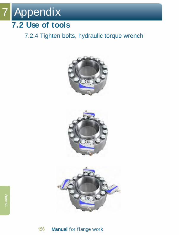
7 Appendix
7.2 Use of tools
7.2.4 Tighten bolts, hydraulic torque wrench
Manual for flange work
Appendix

Manual for flange work
Appendix 7
7.2 Use of tools
7.2.4 Tighten bolts, hydraulic torque wrench
Appe
ndix
Tightening procedure with 1 tools 1. 1 round crosswise to 30% of specified torque. 2. 1 round crosswise to 60% of specified torque. 3. 2 rounds crosswise to 100% of specified torque. 4. After final torque-up, all bolts must be
checked at full torque. 5. Perform the check clockwise.
Tightening procedure with 2 tools
This procedure also applies when a torque wrench is used.
1. 1 round crosswise to 50% of specified torque. 2. 2 rounds crosswise to 100% of specified torque. 3. After final torque-up, all bolts must be
checked at full torque. 4. Perform the check clockwise.
Tightening procedure with 4 tools 1. Tighten all bolts to the torque specified in
the torque table 2 times. 2. Check that the tools are positioned in a
cross formation at all times. 3. After final torque-up, all bolts must be
checked at full torque. 4. Perform the check clockwise.

7 Appendix
7.2 Use of tools
Manual for flange work
Appendix
7.2.5 Tighten bolts, hydraulic tensioner
1. Check that bolt projection over the nut is at least equal to bolt diameter.
2. Position a socket over the nut.
3. Check tool size against the torque table.
4. Fit the bridge and hydraulic head.
5. Fit the threaded puller. The tool is fitted to every alternate bolt around the entire flange.
6. Connect the hydraulic hoses. Check that all quick-release connectors are properly connected up.
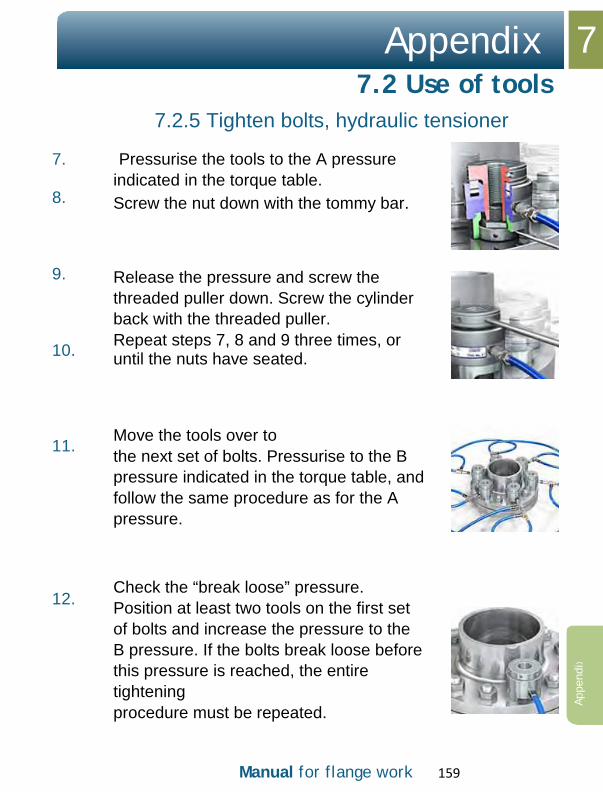
Manual for flange work 159
Appendix 7
7.2 Use of tools
7.2.5 Tighten bolts, hydraulic tensioner
Appe
ndix
7. 8.
9. 10. 11. 12.
Pressurise the tools to the A pressure indicated in the torque table. Screw the nut down with the tommy bar. Release the pressure and screw the threaded puller down. Screw the cylinder back with the threaded puller. Repeat steps 7, 8 and 9 three times, or until the nuts have seated. Move the tools over to the next set of bolts. Pressurise to the B pressure indicated in the torque table, and follow the same procedure as for the A pressure.
Check the “break loose” pressure. Position at least two tools on the first set of bolts and increase the pressure to the B pressure. If the bolts break loose before this pressure is reached, the entire tightening procedure must be repeated.

7 Appendix
7.2 Use of tools
Manual for flange work
Appendix
7.2.6 Tighten bolts, mechanical tensioner Procedure for Stealth and LoaDisc
1. Fit all the bolts in the flange.
Fit the LoaDisc on the side the tool is fitted, and a normal nut on the opposite side. Once the LoaDisc has been fitted, the bolt should project by approx. one bolt diameter. No counter-hold needed; no pinch points.
h = min. bolt diameter
2. Lubricate the bolt threaded section and the nut mating face with an even film of specified lubricant. Fit the final nuts, so that the LoaDisc acts as a washer between nut and flange on the side the tool is fitted.

Manual for flange work 161
Appendix 7
7.2 Use of tools
7.2.6 Tighten bolts, mechanical tensioner
Appe
ndix
Procedure for Stealth and LoaDisc
3. Tighten the flanges:
3.1 Fit the tools in a cross-formation and set the pump to 100% of the specified pump pressure. Use the torque table for LoaDisc. Follow the standard tightening procedure.
3.2 Fit the tools to every alternate bolt and tighten to 100% of the specified pump pressure. Use the torque table for LoaDisc. Follow the standard tightening procedure.

7 Appendix
7.2 Use of tools
162 Manual for flange work
Appendix
7.2.7 Tighten bolts, mechanical tensioner, Procedure for Avanti and ClampNut
1. Fit all the bolts in the flange. Lubricate the bolt
threaded section on the side the ClampNut is fitted. Fit the Hytorc ClampNut. Make sure all threads are in contact.
No counter-hold needed; no pinch points.

Manual for flange work
Appendix 7
7.2 Use of tools
Appe
ndix
7.2.7 Tighten bolts, mechanical tensioner, Procedure for Avanti and ClampNut
2. Tighten the flanges:
2.1 Fit the tools to every alternate bolt and tighten to 100% of the specified pump pressure. Use the torque table for ClampNut. Follow the standard tightening procedure.
2.2 Fit the tools to all
bolts and tighten to 100% specified pump pressure. Use the torque table for ClampNut. Follow the standard tightening procedure.

164 Manual for flange work
7 Appendix
7.3 Tables Bolts
Appendix

Appendix 7
7.3 Tables Bolts
Manual for flange work
Appe
ndix

7 Appendix
7.3 Tables Bolts
Manual for flange work
Appendix

Appendix 7
7.3 Tables Bolts
Manual for flange work 167
Appe
ndix

168 Manual for flange work
7 Appendix
7.4 Tables ASME RTJ, gap
Appendix

Manual for flange work 169
Appendix 7
7.4 Tables ASME RTJ, gap
Appe
ndix
Example Class 150 NPS 4: The flange connection has a nominal gap of 4 mm
Key Class: Pressure class NPS 4: 4" flange

170 Manual for flange work
7 Appendix
7.4 Tables ASME RTJ, gap
Appendix

Manual for flange work 171
Appendix 7
7.4 Tables ASME RTJ, gap
Appe
ndix

172 Manual for flange work
7 Appendix
7.5 Tables, API 6A type 6B – gap
Appendix

Manual for flange work 173
Appendix 7
Appe
ndix
7.5 Tables, API 6A type 6B – gap
>> continued from page 170

174 Manual for flange work
7 Appendix
7.6 Spring supports
Appendix
7.6.1 Pipe supports with springs
A pipe system is affected by many different factors:
• Temperature • Pressure • Flow factors • Deformations sustained • Wind • Explosion • Etc.
Manual for flange work 175
Appendix
7.6 Spring supports 7
Appe
ndix
To counteract these effects, a pipe system must be supported in a controlled manner. The purpose of the support is to fix the system at individual points, while still allowing it to move at others. It is particularly important that there are no clamping forces due either to temperature or to deformations sustained.
In some cases, it is difficult to achieve support that ensures the pipe will not be overloaded due to the weight, at the same time as preventing clamping forces resulting from temperature or deformations sustained. In such cases, springs are often used, so-called “spring supports”.

176 Manual for flange work
7 Appendix
7.6 Spring supports
7.6.2 Purpose behind
Appendix
Spring supports are often used in situations where stubs to equipment are involved. A stub on a tank, pump, compressor or similar, has a limited capacity for cushioning forces from the pipe system. A pipe support must therefore normally be installed in the immediate vicinity of the stub, to take the load off it.
In an ideal world without movement in the stub or thermal expansion of the pipe, this could be done using a normal pipe support. In practice, however, it is often the case that the stub moves in relation to the pipe system’s other pipe supports. This is generally due to the fact that the equipment undergoes thermal expansion between its fixed point and the stub.

Appendix
7.6 Spring supports
7.6.2 Purpose behind springs
7
Manual for flange work
Appe
ndix
For a tank with a diameter of 5 m and connecting stub to the pipe system positioned on the top of the tank, the stub will move approx. 6 mm in a vertical direction if the tank has a temperature variation of 100◦C.
Figure 1.

7 Appendix
7.6 Spring supports
7.6.2 Purpose behind
178 Manual for flange work
Appendix
If an ordinary “rest support” (fixed pipe support) had been installed in the vicinity of the stub, the pipe would simply have lifted away from this pipe support when the tank became warm. (See Figures 2 and 3.) If the tank had been cooled down, the pipe would have pressed down against the pipe support/beam, possibly resulting in significant restraining forces.
If the pipe support is replace by a flexible item (see Figure 3), such as a spring, most of the pipe’s weight will be supported by the spring. The spring will “follow” the movement of the tank when the latter is subjected to changes in temperature.

Appendix
7.6 Spring supports
7.6.2 Purpose behind springs
7
Figure
Manual for flange work 179
Appe
ndix
Figure 2.

180 Manual for flange work
7 Appendix
7.6 Spring supports
7.6.3 Variable springs
Appendix
The simplest type of spring support is a so-called variable spring support. This is normally a device based on a spiral spring. A spring of this type is characterised by three parameters:
• Preload • Spring constant • Permissible travel
The springs come in various models of differing length, diameter and thickness, to achieve the required parameters. The spring constant is fixed for a specific spring, but the preload can be changed to some extent by adjusting the spring.
Normally, a variable spring support is constructed as shown in Figures 4, 5 and 6.

Appendix
7.6 Spring supports
7.6.3 Variable springs
7
Figure
Manual for flange work 181
Appe
ndix

7 Appendix
7.6 Spring supports
7.6.3 Variable springs
182 Manual for flange work
Appendix
Figure 5.

Appendix
7.6 Spring supports
7.6.3 Variable springs
7
Manual for flange work 183
Appe
ndix
Figure 6.
The spiral spring proper is contained in a cylinder. A circulate plate above the spring is linked to a steel bar that transfers the force from the pipe.
Some spring supports have a slotted groove in the cylinder so that the plate can be locked in a given position corresponding to the correct preload. (See Figure 4.) The locking plate is sometimes not removed as it should be when the pipe system is brought into operation. (See Figure 8.)
Other springs use lock nuts. (See Figures 5 and 6.)

7 Appendix
7.6 Spring supports
7.6.3 Variable springs
184 Manual for flange work
Appendix
When the spring support is supplied, the spring is compressed to the correct preload, and metal inserts are present to lock the plate in this position. This is to facilitate correct installation of the spring support. (See Figure 4.)
For the type of spring support that uses lock nuts, you can check the spring has the correct load by attempting to rotate the lock nuts on either side of the spring plate. If you encounter significant resistance, the spring is not correctly installed and adjusted. Adjustment is effected by turning the turnbuckle, for instance. (See Figures 5, 10 and 11.)
The slotted groove is marked with a scale so that you can read off the spring force by comparing the position of the plate above the spring in regard to the scale. The same scale indicates the amount of travel the spring permits in each direction. (See Figures 7 and 9.)

Appendix
7.6 Spring supports
7.6.3 Variable springs
7
Manual for flange work 185
Appe
ndix
Figure 7.
locked spring
Figure 8.

7 Appendix
7.6 Spring supports
7.6.3 Variable springs
186 Manual for flange work
Appendix
Figure 9.

Appendix
7.6 Spring supports
7.6.3 Variable springs
7
Manual for flange work 187
Appe
ndix
Figure 10.
Figure 11.

188 Manual for flange work
7 Appendix
7.6 Spring supports
7.6.4 Constant springs
Appendix
In some contexts, it is not acceptable that the support forces should vary with movement of the pipe. This is often the case where stubs on sensitive equipment are involved in significant movement.
In such contexts, constant spring supports are often used. These are devices that provide an almost constant support force. In their simplest embodiment, they can be as simple as a weight that exerts a constant force via a pulley.

Appendix
7.6 Spring supports
7.6.4 Constant springs
7
Manual for flange work 189
Appe
ndix
Figure 12.
7 Appendix
7.6 Spring supports
7.6.4 Constant springs
Manual for flange work
Appendix
In an offshore context, however, the most common solution is a spiral spring which acts on the pipe via a mechanism, with a geometry designed to ensure the mechanism compensates any change in spring force.
A constant spring is characterised by two parameters:
• Load • Permissible travel
The desired load can be adjusted to some degree for a specific spring.

Appendix
7.6 Spring supports
7.6.4 Constant springs
7
Manual for flange work 191
Appe
ndix
Figure 13.

7 Appendix
7.6 Spring supports
7.6.4 Constant springs
192 Manual for flange work
Appendix
A constant spring support is also equipped with a transport retaining device. This normally consists of a bolt that locks the mechanism.
Figure 14.
There is a small indicator that marks the position of the spring in relation to the total travel permitted by it. (See Figure 15.) Two positions are normally marked off on the scale. One position corresponds to the position for the spring on installation, and the other to its position when the pipe is in operation.

Appendix
7.6 Spring supports
7.6.4 Constant springs
7
Manual for flange work 193
Appe
ndix
The supplier of the spring support sets these marks on the basis of the information provided in the order. This information is based on a stress analysis. The spring forces marked on the spring support should normally be the same as in the “stress iso”.
Figure 15.

194 Manual for flange work
7 Appendix
7.6 Spring supports
Appendi
7.6.5 Installation in a cold system
The supplier will normally have produced an installation manual which must be followed by personnel effecting installation. If no installation manual has been included in the work package, the unit performing the work must request one be sent and must study it carefully before carrying out the work.

Appendix
7.6 Spring supports
7.6.5 Installation in a cold system
7
Manual for flange work
Appe
ndi
The spring support is installed mechanically and the turnbuckle adjusted until the transport retainers begin to loosen. The transport retainers are then removed. (See Figures 4 and 8.)
Some spring support types use nuts to lock and adjust travel. Check the installation manual. (See Figures 10, 11 and 16.)
Figure 16.
The procedure is in principle the same for variable spring supports as for constant ones.

196 Manual for flange work
7 Appendix
7.6 Spring supports
Appendix
7.6.6 Installation in a warm system
On arrival from the supplier, the spring support is adjusted for installation in a cold system. This means that if the spring support is installed as described above, the spring’s position will be correct for installation in a cold system. Compensation must therefore be made for the fact that the pipe is not in the installation position.
To achieve this, the person responsible for the installation must find out the actual height of the pipe. This should normally be derived from a stress iso. Here, however, you need to bear in mind that the values stated in a stress iso normally refer to the design temperatures, and you cannot assume the pipe in question is at this precise temperature at the time of installation.
A typical example of this particular problem is provided by spring supports on flow lines. A flow line links the Christmas tree with the production and testing manifolds. Due to a combination of pressure, temperature and settlement at the bottom, the Christmas tree will move up and down. When the flow line is in operation at max. temperature and pressure, the flow line stub will be in its highest position, corresponding to the deformation used in the stress calculations. When a spring support is to be installed on a flow line in operation, the flow line will normally

Appendix
7.6 Spring supports
7.6.6 Installation in a warm system
7
Manual for flange work
Appe
ndix
be in a position somewhere below the max. height, depending on the temperature and pressure of the medium. In such a situation, you need to assess the position the spring is to be adjusted to. You cannot simply set it to the “installation position”, as this is the position for a cold well.
If the spring support is installed as if the well were cold, the spring will have nowhere to travel once the well goes down again. This will result in abnormally large support forces which are potentially damaging.
The spring support is installed mechanically and the turnbuckle adjusted until the transport retainer begins to loosen. The transport retainer is then removed. Once the transport retainer is removed, the turnbuckle must be adjusted further to compensate for the fact the pipe is not in the cold position. This means that, if the pipe is 10 mm higher than it would have been in the cold position, the spring must be tensioned by 10 mm.
Inserting a spring support in a warm system is a demanding job requiring expert appraisals and insight. Normally the responsible Pipe Stress Engineer must be contacted to provide advice and guidance to those due to perform the installation work.

198 Manual for flange work
7 Appendix
7.6 Spring supports
7.6.7 Inspection
Appendix
When inspecting existing spring supports, the following items must be checked:
1. Locking blocks/lock nuts (variable spring
supports) or lock pins (constant spring supports) must be removed.
2. The position of the spring in relation to the
system’s movements must be correct. Check this. If the scale is not visible, the spring support must normally be replaced.
Different factors can result in the situation changing over time so that the spring leaves its original position. This can result in the spring leaving its working range and moving to its end position. If this happens, the spring is acting as a fixed support and the installation is liable to be damaged.

Appendix 7
Manual for flange work 199
Appe
ndix
7.6 Spring supports
7.6.7 Inspection
3. General condition: Over time, the spring may be damaged due to corrosion. Finally the spring characteristics will change due to the reduction in material, or parts of the spring breaking off.
4. Check that the spring support can be loaded.
5. Condition of stay and clamp around the pipe.
6. Check that moving parts are not so corroded that they do not work.
7. A spring support must not be replaced with a
chain, stay or similar, without prior approval for this from the responsible Pipe Stress Engineer.

7 Appendix
7.6 Spring supports
7.6.7 Inspection
200 Manual for flange work
Figure 18.
Appendix
Figure 17. Drawing with an example of a hanger arrangement with spring support.
Figure 18. Example of a detail drawing of a spring support. Notice that the lock nuts are in the locked position and the spring is preloaded.

Manual for flange work 201
Appendix 7 7.7 Checklist
for leaking flanges
Appe
ndix
(installation) TAG NO: ____________ 1: Flange size _______ Pressure class _________Spec :__________
A: Flange material: Flange 1 __________ Flange 2 _________
B: Bolt size _______ bolt grade ____________
C: Flange stand-off 12 o’clock____ 3 o’clock_____ 6
o’clock _____ 9 o’clock____ D: Flange stand-off at sealing face: 12 o’clock_____ 3
o’clock____ 6 o’clock____ 9 o’clock____
E: Tool type used ________ Tool number ________ pump pressure _________
number of tools _______ Lubricant used ________
F: Gasket type used_________ Material________ Size ___________ G: Stress in the
pipe system ____________ Is pipe aligned before tightening? ________
H: Has the flange been signed off?___________ Has the right table been used? _____________
I: What is the break-loose pump pressure for the nuts?______PSI What tool no.?________
What is the equivalent in NM? ___________ What is the tightening torque for this in the
table?:______
2: Is the ring based on a pipe spec. or a torque table? _________________
A: Is the ring deformed? ____Is it equally deformed? _____Is it deformed at certain points?______
B: Does the ring move when inserted in the groove?_____________ C: When
a new ring is used, does it move?____________
D: Has a blind flange been used?_________ Is it undamaged?___________ E:
Have the rings been used a number of times?_____________
F: Have the flanges been used a number of times?
_____________ G: Is the ring groove within the
tolerances?___________
H: Have any foreign bodies been found in the sealing faces?________ If so, what?_______ Date:__________________ Sign.____________________

202 Manual for flange work
7 Appendix
Appendix
7.7 Checklist for leaking flanges
If a flange leaks: Bleed down the pressure!
1. Check flange face parallelism; use vernier calipers at 12-3-6 and 9 o’clock. See the tightening procedure
2. Check that the torque table used is correct for the line number in question.
3. Verify that all bolts have been tightened to the correct torque. See the tightening procedure.

Appendix 7 7.7 Checklist
for leaking flanges
Manual for flange work 203
Appe
ndix
4. If the flange still leaks, disassemble and check:
Gasket type, material grade, gasket size and pressure class.
Deformations and damage on the flange/mating
faces. Report to qualified personnel for further assessment.
5. Check that the mating faces and bolt threaded section have been properly lubricated. Lubricate all the bolts.
6. Insert a new gasket and start the tightening procedure in accordance with the torque table in question.

7 Appendix
204 Manual for flange work
Appendix
7.8 Example of flange identification tag

Manual for flange work 205
Appendix 7
Appe
ndix

206 Manual for flange work
7 Appendix
Appendix
7.9 Example: “Activity and inspection schedule”

Appendix 7
Manual for flange work
Appe
ndix

7 Appendix
208 Manual for flange work
Appendix
7.10 Revision history
7.10.1 Rev. 02, March 2009
1. General updates. Division into chapters added. Bullet points replaced by numbered lists.
2. Competence requirements, page 6 rev. 02
Requirements on training and certification when working on composite materials (GRE, GRP) added.
3. API 6A type 6BX - Follow-up inspection, page 88 rev. 02
Information about the flange having to come fully together inside at the ring removed.
4. NCF5 - Alignment, Skewed connection, page 108 rev. 02
Procedure for alignment modified.
5. NCF5 - Tightening, page 119 rev. 02 Procedure for use of tools modified.
6. Appendix - Tables, bolts, pages 162 - 164 rev. 02
Tables for bolts modified/redesigned.
7. Appendix - Tables, ASME RTJ, gap, pages 166 - 199 rev. 02 added.
8. Appendix - Tables, API 6A type 6B, gap, pages 170 - 171 rev. 02 added.
9. Appendix - Revision history, page 206 rev. 02 added.

Appendix 7
Manual for flange work 209
7.10 Revision history
7.10.2. Rev. 03, September 2011
1. Linguistic enhancements to correct errors and reduce the potential for misunderstanding of the text.
2. Reference to internationally accepted standards.
3. Text adjusted to render OLF’s role relating to course
implementation more precise.
4. Permitted bolt load when aligning ASME RTJ, ASME RF/ FF and API 6A type 6B/BX flanges modified.
5. Appendix - Revision history, page 209 rev. 03 added.