fire detection and alarm system - cormetonalarm systems: electromagnetic compatibility product...
TRANSCRIPT

Fire detection and alarm systemInstallation instructions

2
Installation instructions
Table of Contents
Table of Contents - - - - - - - - - - - - - - - - - - 2
Preface - - - - - - - - - - - - - - - - - - - - - - - 3
Associated Documents · · · · · · · · · · · · · · · · · 3
Conventions · · · · · · · · · · · · · · · · · · · · · · · 3
Notes on system installation - - - - - - - - - - 4Installation requirements - - - - - - - - - - - - - - - 4
Second fix installation - - - - - - - - - - - - - - - - 4
Fixture and fittings- - - - - - - - - - - - - - - - - - 4
As fitted drawings - - - - - - - - - - - - - - - - - - 4
Fire sensor covers - - - - - - - - - - - - - - - - - - 4
Earth continuity - - - - - - - - - - - - - - - - - - - 4
Mains supply - - - - - - - - - - - - - - - - - - - - 4
System wiring - - - - - - - - - - - - - - - - - - - - 5
Cable separation · · · · · · · · · · · · · · · · · · · · · 5
Lightning protection · · · · · · · · · · · · · · · · · · · 5
Typical Vigilon Compact system architecture - - - - - 6
Vigilon Compact panel (Compact-24) - - - - - 7Features · · · · · · · · · · · · · · · · · · · · · · · · · 7
Technical specification- - - - - - - - - - - - - - - - 7
Control panel · · · · · · · · · · · · · · · · · · · · · · 7
Power supply · · · · · · · · · · · · · · · · · · · · · · 8
Installation checks - - - - - - - - - - - - - - - - - - 9
Cable termination points on the enclosure - - - - - - - 9
Loop cable - - - - - - - - - - - - - - - - - - - - - 10
EMC approved cables for loop wiring · · · · · · · · · 10
Mains Supply cable - - - - - - - - - - - - - - - - - 10
Terminate and mark the cables - - - - - - - - - - - - 10
Wiring test · · · · · · · · · · · · · · · · · · · · · · · · 10
Mains supply - - - - - - - - - - - - - - - - - - - - 11
Mains and battery supply connections- - - - - - - - - 11
How to flush mount the control panel - - - - - - - - - 12
Surface fixing · · · · · · · · · · · · · · · · · · · · · · 12
Removable terminal block - - - - - - - - - - - - - - 13
Terminals for external circuit - - - - - - - - - - - - - 13
Loop circuit - - - - - - - - - - - - - - - - - - - - - 14
Master alarm circuits- - - - - - - - - - - - - - - - - 15
Auxiliary relay circuits- - - - - - - - - - - - - - - - 15
Clean contacts - - - - - - - - - - - - - - - - - - - - 15
Repeat indicator panel - - - - - - - - - - - - - - - - 15
Cable · · · · · · · · · · · · · · · · · · · · · · · · · · · 15
Monitored input circuit- - - - - - - - - - - - - - - - 16
RS232 / RS485 Ports - - - - - - - - - - - - - - - - 16
USB Port - - - - - - - - - - - - - - - - - - - - - - 16
Connecting an external printer - - - - - - - - - - - - 16
On completion of panel installation - - - - - - - - - - 17
Repeat indicator panel - - - - - - - - - - - - - 18Technical Specification - - - - - - - - - - - - - - - 18
Installation - - - - - - - - - - - - - - - - - - - - - 18
Repeat Panel (loop connected) - - - - - - - - - 19Technical Specification - - - - - - - - - - - - - - - 19
Installation - - - - - - - - - - - - - - - - - - - - - 20
Surface or flush the repeat panel · · · · · · · · · · · · 20
A2 Mimic and Zonal mimic Panel - - - - - - - 21Technical Specification - - - - - - - - - - - - - - - 21
Installation - - - - - - - - - - - - - - - - - - - - - 22
A4 Mimic and Zonal mimic panel sets - - - - - 23Technical specification- - - - - - - - - - - - - - - - 23
Cable types - - - - - - - - - - - - - - - - - - - - - 24
Installation - - - - - - - - - - - - - - - - - - - - - 24
Display unit · · · · · · · · · · · · · · · · · · · · · · · 24
Control unit · · · · · · · · · · · · · · · · · · · · · · · 25
Terminal plates, Trim ring and flush kit- - - - - 26Terminal plate installation - - - - - - - - - - - - - - 27
Trim ring installation - - - - - - - - - - - - - - - - 28
Semi flush installation - - - - - - - - - - - - - - - - 28
Fire sensors - - - - - - - - - - - - - - - - - - 29Exploded view of a sensor· · · · · · · · · · · · · · · · 29
Optical Sensor- - - - - - - - - - - - - - - - - - - - 30
Optical Heat Sensor - - - - - - - - - - - - - - - - - 30
Optical Heat Sounder - - - - - - - - - - - - - - - - 31
Heat Sensor - - - - - - - - - - - - - - - - - - - - - 31
Heat Sounder - - - - - - - - - - - - - - - - - - - - 32
Fitting a Sensor head to the terminal plate- - - - - - - 32
Removal of Sensor head from terminal plate - - - - - 33
To assemble a sensor head - - - - - - - - - - - - - - 33
'T' breaker and slave units - - - - - - - - - - - 34Technical specification- - - - - - - - - - - - - - - - 34
Installing a 'T' breaker or slave unit - - - - - - - - - - 35
Beam sensor - - - - - - - - - - - - - - - - - 36Technical specification- - - - - - - - - - - - - - - - 36
Installation - - - - - - - - - - - - - - - - - - - - - 37
Duct Sensor - - - - - - - - - - - - - - - - - - 38Technical specification- - - - - - - - - - - - - - - - 38
Installation - - - - - - - - - - - - - - - - - - - - - 39
S3 Speech, Sounder Strobe - - - - - - - - - - - 40Speech messages· · · · · · · · · · · · · · · · · · · · · 40
Technical specification- - - - - - - - - - - - - - - - 40
Installation - - - - - - - - - - - - - - - - - - - - - 41
Terminal block for retrofit installation of System S3 · · 41
Sounder standard type - - - - - - - - - - - - - 42Technical specification- - - - - - - - - - - - - - - - 42
Installation - - - - - - - - - - - - - - - - - - - - - 42
Environmentally protected products - - - - - - 43
Manual call points - - - - - - - - - - - - - - - 44Technical specification- - - - - - - - - - - - - - - - 44
Installation - - - - - - - - - - - - - - - - - - - - - 45
Zone module (loop powered)- - - - - - - - - - 46Technical specification- - - - - - - - - - - - - - - - 46
Installation - - - - - - - - - - - - - - - - - - - - - 47
Single channel interface (loop powered) - - - - 48Technical specification- - - - - - - - - - - - - - - - 48
Installation - - - - - - - - - - - - - - - - - - - - - 49
Four channel interface (loop powered) - - - - - 50Technical specification - - - - - - - - - - - - - - - 50
Installation - - - - - - - - - - - - - - - - - - - - - 51
Keyswitch door · · · · · · · · · · · · · · · · · · · · · 51
Power supply unit (for 4 channel loop poweredinterface) - - - - - - - - - - - - - - - - - - - 52
Installation - - - - - - - - - - - - - - - - - - - - - 52
Mains powered interface unit- - - - - - - - - - 53Technical specification- - - - - - - - - - - - - - - - 53
Installation - - - - - - - - - - - - - - - - - - - - - 54
Vigilon compact system parts - - - - - - - - - 56

Preface
This is the first issue of the Installation instructions for the VigilonCompact fire panel. The manual covers information on how to installthe panel and loop devices of the system.
These instructions must be read in conjunction with therecommendations in BS5839:Part 1, which is the code of practice for Firedetection and alarm system for buildings.
Associated DocumentsOperating instructions
Log book
Conventions
� This is a note to highlight important text that isnormally hidden in the main text.
� This is either a caution to prevent damage to theequipment or a warning to inform of dangerous conditionsthat may result in injury or death.
The information in this manual is being supplied without liability for errors or
omissions. No part of the manual may be reproduced in any form whatsoever
without prior consent of the company. Due to the on going development
of products the information contained in this manual is subject to change without
notice.
3
Vigilon COMPACT

Notes on systeminstallation
The power-up of the control panel andcommissioning of the system is done by the
Servicing organisation.
Installation requirements
It is recommended that the installer follow the general requirements ofBS5839:Part 1, which is the code of practice relating to the fire detectionand alarm systems for buildings. The installer must follow the relevantparts of BS7671 : 1992 Requirements for Electrical installations, IEE wiring
regulations 16th edition if installation is in the United Kingdom, UK.
Second fix installation
To prevent the possibility of damage or dirt degrading the performance orappearance of the products, the installation of second fix items should bedelayed until all major building work in the area is complete.
� The installation of all outstanding parts are usuallycarried out during commissioning of the system.
Fixture and fittings
It is the installers responsibility to provide adequate fixtures and fittingsfor the type of construction surface onto which a product is to beinstalled, whilst utilising the fixing points on the respective product. As anaid to this decision, the weight and overall size of each full assemblytogether with implications on cable entries and routing should be takeninto consideration.
� All these procedures assume that the cable, gland,steel box (BESA box) and other related accessories are providedby the installer.
As fitted drawings
The installer should acquire site specific information from the interestedparties, for details on the location of products for installation. Theacquired information together with this guide and the relevant standardsshould be used to assist the work.
Each product assembly can be identified from its package label. Thecontents of all packages should be checked for any discrepancies.
Fire sensor covers
Each fire sensor may be supplied with a plastic dust cover. If suppliedthe cover must be fitted to prevent dust and dirt from the building workcontaminating the fire sensor.
Earth continuity
All earth connection points should be clean to provide a goodelectrical conductivity path. To maintain the earth continuity: allearth leads and fittings provided should be installed, the loop cablescreen must be continued through each system device on the loopcircuit, whether the earth is connected to the device or not.
� Do not use any part of building structure for earthing.
Some of the system products having metal enclosures have zinccoating around the cable termination points, the coating provides agood electrical conductivity path for cable earth termination.
The zinc coating on metal enclosure should not be damaged. Anydamage will expose bare metal, which can corrode and make poor earthconnection.
Mains supply
The Mains Supply to mains powered equipment must be via a 2-poleunswitched fused spur unit (Disconnect device). The Disconnect deviceshould be available as part of the building installation.
4
Installation instructions
System wiring
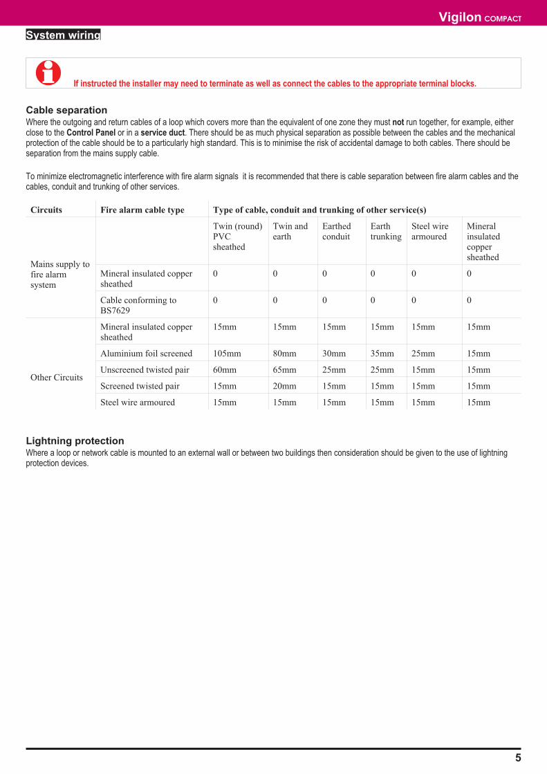
� If instructed the installer may need to terminate as well as connect the cables to the appropriate terminal blocks.
Cable separationWhere the outgoing and return cables of a loop which covers more than the equivalent of one zone they must not run together, for example, eitherclose to the Control Panel or in a service duct. There should be as much physical separation as possible between the cables and the mechanicalprotection of the cable should be to a particularly high standard. This is to minimise the risk of accidental damage to both cables. There should beseparation from the mains supply cable.
To minimize electromagnetic interference with fire alarm signals it is recommended that there is cable separation between fire alarm cables and thecables, conduit and trunking of other services.
Circuits Fire alarm cable type Type of cable, conduit and trunking of other service(s)
Mains supply tofire alarmsystem
Twin (round)PVCsheathed
Twin andearth
Earthedconduit
Earthtrunking
Steel wirearmoured
Mineralinsulatedcoppersheathed
Mineral insulated coppersheathed
0 0 0 0 0 0
Cable conforming toBS7629
0 0 0 0 0 0
Other Circuits
Mineral insulated coppersheathed
15mm 15mm 15mm 15mm 15mm 15mm
Aluminium foil screened 105mm 80mm 30mm 35mm 25mm 15mm
Unscreened twisted pair 60mm 65mm 25mm 25mm 15mm 15mm
Screened twisted pair 15mm 20mm 15mm 15mm 15mm 15mm
Steel wire armoured 15mm 15mm 15mm 15mm 15mm 15mm
Lightning protectionWhere a loop or network cable is mounted to an external wall or between two buildings then consideration should be given to the use of lightningprotection devices.
5
Vigilon COMPACT
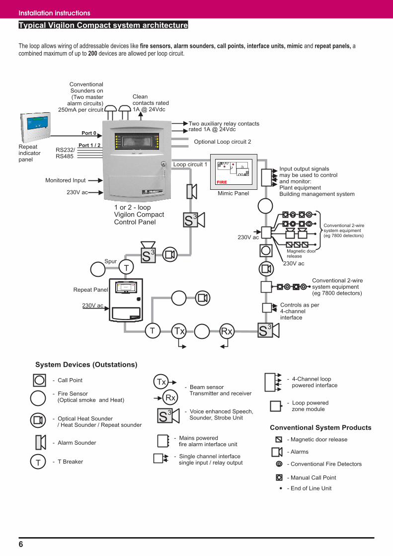
Typical Vigilon Compact system architecture
The loop allows wiring of addressable devices like fire sensors, alarm sounders, call points, interface units, mimic and repeat panels, acombined maximum of up to 200 devices are allowed per loop circuit.
6
Installation instructions
Repeat Panel
Conventional 2-wiresystem equipment(eg 7800 detectors)
Conventional 2-wiresystem equipment(eg 7800 detectors)
230V ac
Magnetic doorrelease
230V ac
230V ac Controls as per4-channelinterface
Spur
Optional Loop circuit 2
1 or 2 - loopVigilon CompactControl Panel
Input output signalsmay be used to controland monitor:Plant equipmentBuilding management system
ConventionalSounders on(Two master
alarm circuits)250mA per circuit
Two auxiliary relay contacts
Cleancontacts rated1A @ 24Vdc
rated 1A @ 24Vdc
Fault
Power
CommissionSystem Fault
Fire
Disablement
Previous Next
Panel healthy 12:00
Vigilon Fire SystemGENT 1998
T
Tx Rx
System Devices (Outstations)
- Call Point
- Fire Sensor(Optical smoke and Heat)
- Optical Heat Sounder/ Heat Sounder / Repeat sounder
- Alarm Sounder
- T BreakerT
- End of Line Unit
- Magnetic door release
Conventional System Products
- Alarms
- Conventional Fire Detectors
- Manual Call Point
- Loop poweredzone module
- 4-Channel looppowered interface
Loop circuit 1
T S3
S3
S3
- Single channel interfacesingle input / relay output
- Mains poweredfire alarm interface unit
- Beam sensorTransmitter and receiver
Tx
Rx
S3 - Voice enhanced Speech,
Sounder, Strobe Unit
Repeatindicatorpanel
RS232/RS485
Monitored Input
Port 0
Port 1 / 2
230V ac
FIRE
Mimic Panel

Vigilon Compact panel(Compact-24)The Vigilon Compact is an analogue addressable fire alarm panelconforming to the requirements of EN54 Parts 2 and 4. The panel isdesigned for use with the Vigilon range of analogue and addressabledevices. It houses its own power supply with batteries to supply standbypower in the event of mains supply failure. A lockable front door preventsunauthorised access to fire alarm controls but allows all of the indicatorsto be seen. The panel is designed for flush and surface mounting andfacilitates both rear and top cable entry points. The Compact-24 panelcomes in a smaller enclosure and provides 24 hour standby.
Features
� Analogue addressable fire alarm control panel
� Supports up to two loop circuits per panel
� Up to 200 addressable devices can be connected to a loopcircuit
� Two master alarm circuits
� Dedicated connection to repeat indicator panel
� Configurable Ports 0, 1 and 2 for RS232 and RS485communication to facilitate connection of repeat indicatorpanel, printer, commissioning tool
� Two sets of auxiliary relay change over contacts configurableto operate with fire, fault or disablement
� One set of clean voltage-free change over contacts thatoperate with fire events
� Monitored input that actions a command build 250
� Standby supply to power the system via batteries for 24 hours
� LCD alphanumeric type with back light to display eventinformation.
� LED lights for event indication
� Local audible buzzer to announce events
� Menu controls
Technical specification
Control panel
Standard EN54 Part 2
Panel dimensions in mm
Compact-24 height 403 x width 338 x depth 101
Panel weight
Compact-24 approximately 8.6Kg without batteries
1 - 12V 12Ah battery weight is 4Kg
Storage temperature -30 to 70ºC
Operating temperature 0 to 45ºC
Relative Humidity (Noncondensing)Temperature 5 - 45°C
up to 90%
Emission BS EN50081-1:1992 Part 1 Residential,Commercial & Light IndustryClass B limits
Immunity BS EN50130-4: 1996: Part 4Alarm systems: ElectromagneticcompatibilityProduct family standard: Immunityrequirements for components of fire,intruder and social alarm systems
Ingress Protection
Compact-24
Compact-72
IP31
IP31 estimated
Colour Door: Grey (Pantone 422)Backbox: Graphite Grey (RAL 7024)
Loops Up to 2 Loops with the secondloop requiring an optional loop card
Devices per loop A maximum of up to 200 addressabledevices / outstations per loop
(Devices like sensors, call point, interfaceunits, repeat and mimic panels.)
Plug in Card Card 1Card 2
Loop card suppliedOptional loop card
Master alarm circuits 2 - (24 volt) 250 mA max per circuit400mA max shared load between the twomaster alarm circuits
MA1 - fuse 250mA FS1 on Master controlboardMA2 - fuse 250mA FS2 on Master controlboard
Monitored input Normally open input contacts, active whencontacts are closed, which triggerscommand build 250. Circuit is monitoredfor open and short circuit faults.
Clean contacts 1 set of voltage free change over contactsrated 1A @ 24Vdc to operate with fireevent
Ports Port 0
Port 1
Port 2
RS485 -Repeat indicator panel (P15)
RS232 -Commissioning Tool / Printer (P5)
RS485 -Repeat indicator panel (P5)
USB - Future expansion (P16)
The mode and baud rate for Port 0, 1 and2 can be software configured. The factoryconfigured baud is 9600.
7
Vigilon COMPACT
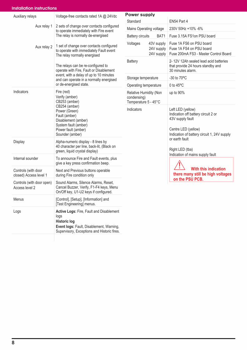
Auxiliary relays
Aux relay 1
Aux relay 2
Voltage-free contacts rated 1A @ 24Vdc
2 sets of change over contacts configuredto operate immediately with Fire eventThe relay is normally de-energised
1 set of change over contacts configuredto operate with immediately Fault eventThe relay normally energised
The relays can be re-configured tooperate with Fire, Fault or Disablementevent, with a delay of up to 10 minutesand can operate in a normally energisedor de-energised state.
Indicators Fire (red)
Verify (amber)CB253 (amber)CB254 (amber)Power (Green)Fault (amber)Disablement (amber)System fault (amber)Power fault (amber)Sounder (amber)
Display Alpha-numeric display - 8 lines by40 character per line, back-lit, (Black ongreen, liquid crystal display)
Internal sounder To announce Fire and Fault events, plusgive a key press confirmation beep.
Controls (with doorclosed) Access level 1
Next and Previous buttons operableduring Fire condition only
Controls (with door open)
Access level 2
Sound Alarms, Silence Alarms, Reset,Cancel Buzzer, Verify, F1-F4 keys, MenuOn/Off key, U1-U2 keys if configured.
Menus [Control], [Setup], [Information] and[Test Engineering] menus.
Logs Active Logs: Fire, Fault and Disablementlogs
Historic log
Event logs: Fault, Disablement, Warning,Supervisory, Exceptions and Historic fires.
Power supply
Standard EN54 Part 4
Mains Operating voltage 230V 50Hz +10% -6%
Battery circuits BAT1 Fuse 3.15A FS1on PSU board
Voltages 43V supply
24V supply
24V supply
Fuse 1A FS6 on PSU board
Fuse 1A FS4 on PSU board
Fuse 200mA FS3 - Master Control Board
Battery 2- 12V 12Ah sealed lead acid batteriesthat provide 24 hours standby and30 minutes alarm.
Storage temperature -30 to 70ºC
Operating temperature 0 to 45ºC
Relative Humidity (Noncondensing)Temperature 5 - 45°C
up to 90%
Indicators Left LED (yellow)Indication off battery circuit 2 or43V supply fault
Centre LED (yellow)
Indication of battery circuit 1, 24V supplyor earth fault
Right LED (tba)
Indication of mains supply fault
� With this indicationthere many still be high voltageson the PSU PCB.
8
Installation instructions
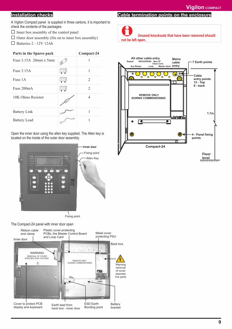
Installation checks
A Vigilon Compact panel is supplied in three cartons, it is important tocheck the contents of the packages:
� Inner box assembly of the control panel
� Outer door assembly (fits on to inner box assembly)
� Batteries 2 - 12V 12Ah
Parts in the Spares pack Compact-24
Fuse 3.15A 20mm x 5mm 1
Fuse 3.15A 1
Fuse 1A 2
Fuse 200mA 2
10K Ohms Resistor 4
Battery Link 1
Battery Lead 1
Open the inner door using the allen key supplied. The Allen key islocated on the inside of the outer door assembly.
The Compact-24 panel with inner door open
Cable termination points on the enclosure
� Unused knockouts that have been removed shouldnot be left open.
9
Vigilon COMPACT
Allen Key
Fixing point
Inner door
Fixing point
Inner door
ESD EarthBonding point
Inner door
Plastic cover protectingPCBs, the Master Control Boardand Loop Card
Metal coverprotecting PSU
REMOVAL OF COVEREXPOSES HIGH VOLTAGE
WARNING
REMOVE ONLYDURING COMMISSIONING
Earth lead fromback box - inner door
Cover to protect PCBdisplay and keyboard
Warningremovalof coverexposeslive parts
Batterybracket
Back box
Ribbon cableand clamp
REMOVE ONLYDURING COMMISSIONING
Compact-24
Mainscableentry
All other cable entryRepeat RS232/RS485 Mon I/P
Clean Cont.
Aux Relays Loop Master alarm
Floorlevel
Cableentry points13 - Top6 - back
7 Earth points
4 - Panel fixingpoints
1.7m
Loop cable
Vigilon loop cable carries both data and power supply and therefore itsselection is important. Note the following:
� In countries where the European EMC directive is in force,only EMC Compliant cables are to be used.
� The loop cable usage must not exceed 1Km. This includes thecable usage on main loop and spur circuits.
� Single pair cable must be used. It is NOT permissible to runmixed loops or outgoing and return pairs in a multi core cable,due to inadequate separation and possible electricalinterference problems.
� Each core of the loop cable must not be less than 1.5mm2
cross section area.
� the cable screen must be capable of being earthed at eachsystem device (outstation).
� Red is the preferred cover sheath for cable used for fireapplication.
� The specified loop circuit cables are also suitable for wiringmaster alarm, auxiliary relay, input/output lines and mainssupply.
EMC approved cables for loop wiring
� Mineral insulated cable (MICC) to BS6207:Part 1
� Delta Crompton FTZ2E1.5 FIRETUF OHLS fire resistantdata cable
� Raydex CDT FG950 *
� Cavicel SpA FIRECEL SR 114 *
distributed by Cables Britain
� AEI Cables FIRETEC *
� BICC Pyrotenax FLAMESIL FRC *
� Datwyler LIFELINE *
� Alcatel cable PYROLON E *
distributed by Winstonlead
� Huber & Suhner RADOX FR *
� Pirelli FP200 FLEX *
� Pirelli FP200 GOLD *
� FP200 GOLD is only approved as being EMCcompliant provided that the date of manufacture is 1998 or after.Cables manufactured before this date MUST NOT be used.
� The cables marked * utilise laminated aluminium tapewith a tinned drain wire for electrostatic screening. Under certainenvironmental conditions galvanic action may take placebetween the aluminium and the drain wire. This will severelydegrade EMC performance as the foil to drain wire impedancewill increase. Therefore these wires should be installed in linewith these instructions and in accordance with theenvironmental conditions as specified by the manufacturer.
Mains Supply cable
The mains supply cable must be a standard fire resisting type and shouldmeet PH30 classification.
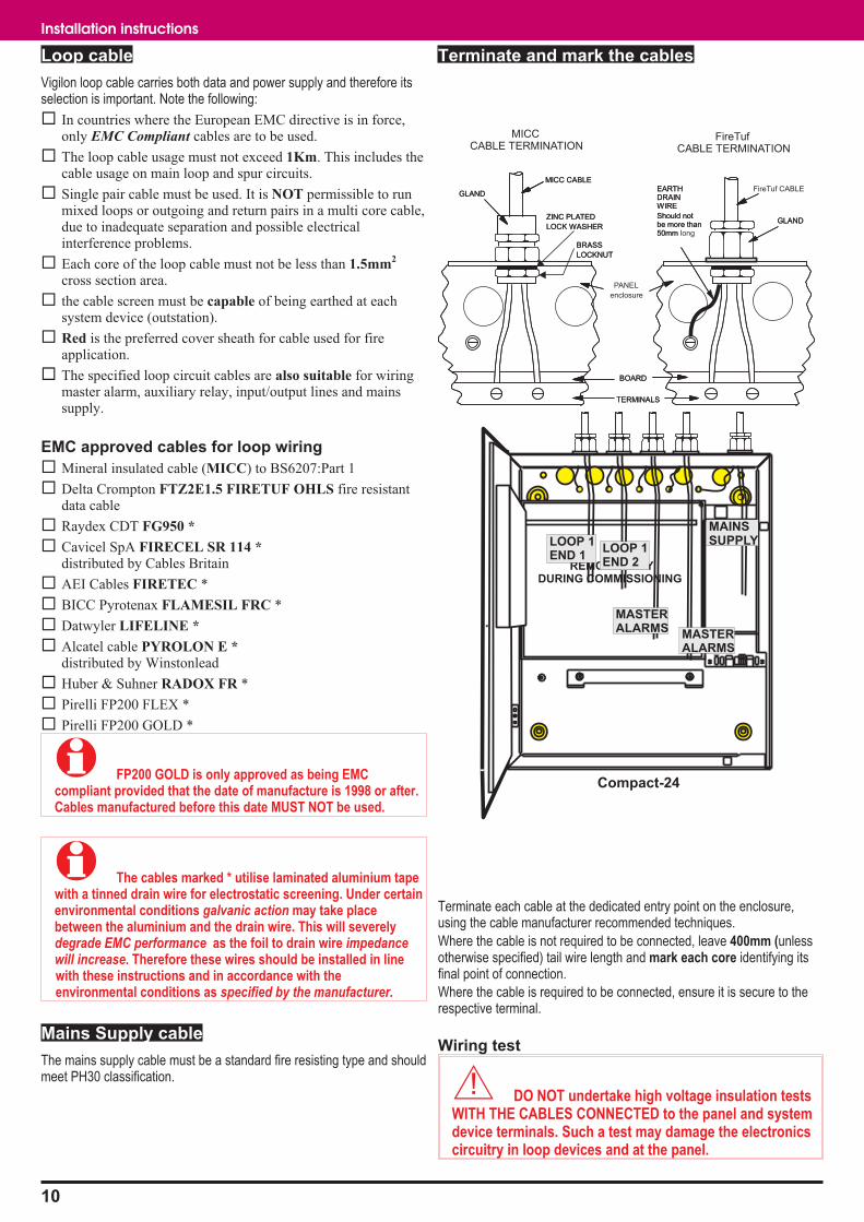
Terminate and mark the cables
Terminate each cable at the dedicated entry point on the enclosure,using the cable manufacturer recommended techniques.
Where the cable is not required to be connected, leave 400mm (unlessotherwise specified) tail wire length and mark each core identifying itsfinal point of connection.
Where the cable is required to be connected, ensure it is secure to therespective terminal.
Wiring test
� DO NOT undertake high voltage insulation testsWITH THE CABLES CONNECTED to the panel and systemdevice terminals. Such a test may damage the electronicscircuitry in loop devices and at the panel.
10
Installation instructions
MICC CABLE
GLAND
BRASS
LOCKNUT
ZINC PLATED
LOCK WASHERGLAND
BOARD
TERMINALS
EARTHDRAINWIRE
Should notbe more than50mm
MICCCABLE TERMINATION
MICC CABLE
GLAND
BRASS
LOCKNUT
ZINC PLATED
LOCK WASHER
FireTuf CABLE
GLAND
BOARD
TERMINALS
EARTHDRAINWIRE
Should notbe more than50mm long
FireTufCABLE TERMINATION
PANEL
enclosure
REMOVE ONLYDURING COMMISSIONING
Compact-24
MAINSSUPPLYLOOP 1
END 1LOOP 1END 2
MASTERALARMS
MASTERALARMS
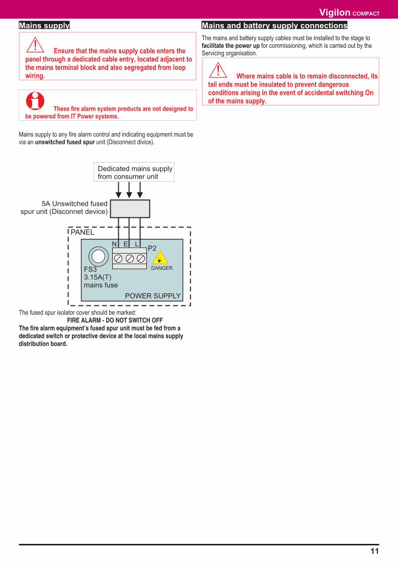
Mains supply
� Ensure that the mains supply cable enters thepanel through a dedicated cable entry, located adjacent tothe mains terminal block and also segregated from loopwiring.
� These fire alarm system products are not designed tobe powered from IT Power systems.
Mains supply to any fire alarm control and indicating equipment must bevia an unswitched fused spur unit (Disconnect divice).
The fused spur isolator cover should be marked:FIRE ALARM - DO NOT SWITCH OFF
The fire alarm equipment’s fused spur unit must be fed from adedicated switch or protective device at the local mains supplydistribution board.
Mains and battery supply connections
The mains and battery supply cables must be installed to the stage tofacilitate the power up for commissioning, which is carried out by theServicing organisation.
� Where mains cable is to remain disconnected, itstail ends must be insulated to prevent dangerousconditions arising in the event of accidental switching Onof the mains supply.
11
Vigilon COMPACT
P2N E L
DANGER
POWER SUPPLY
PANEL
FS33.15A(T)mains fuse
Dedicated mains supplyfrom consumer unit
5A Unswitched fusedspur unit (Disconnet device)
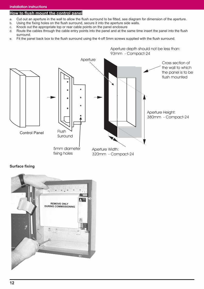
How to flush mount the control panel
a. Cut out an aperture in the wall to allow the flush surround to be fitted, see diagram for dimension of the aperture.b. Using the fixing holes on the flush surround, secure it into the aperture side walls.c. Knock out the appropriate top or rear cable points on the panel enclosured. Route the cables through the cable entry points into the panel and at the same time insert the panel into the flush
surround.e. Fit the panel back box to the flush surround using the 4-off 5mm screws supplied with the flush surround.
Surface fixing
12
Installation instructions
REMOVE ONLYDURING COMMISSIONING
Control Panel
Cross section of
the wall to which
the panel is to be
flush mounted
Aperture
Flush
Surround
5mm diameter
fixing holes
Aperture Height:
380mm - Compact-24
Aperture Width:
320mm - Compact-24
Aperture depth should not be less than:
93mm - Compact-24
Removable terminal block
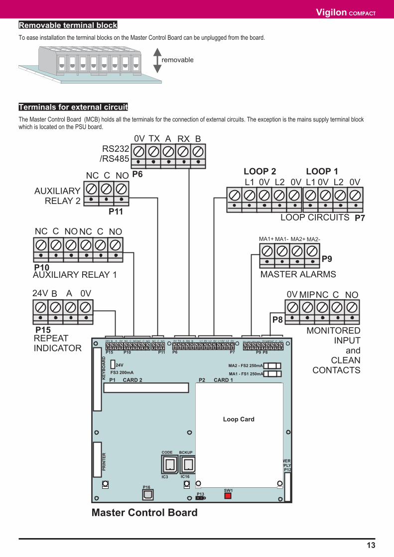
To ease installation the terminal blocks on the Master Control Board can be unplugged from the board.
Terminals for external circuit
The Master Control Board (MCB) holds all the terminals for the connection of external circuits. The exception is the mains supply terminal blockwhich is located on the PSU board.
13
Vigilon COMPACT
removable
P15 P10 P11 P9 P8
P2 CARD 1
IC3
KE
YB
OA
RD
PR
INT
ER
IC16
POWERSUPPLY
P12
MA1 - FS1 250mA
MA2 - FS2 250mA
P1 CARD 2
P16
P13SW1
24V B A 0V NC C NO NC C NONC C NO MA1+ MA1- MA2+ MA2- 0V MIPNC C NO
CODE BCKUP
Loop Card
Master Control Board
P15
P10
P11
P9
P8
P7
P6
24V B A 0V
NC C NO
NC C NO
0V TX A
NC C NO
RX B
L1 0V L2 0V L1 0V L2 0V
MA1+ MA1- MA2+ MA2-
0V MIPNC C NO
REPEATINDICATOR
AUXILIARY RELAY 1
AUXILIARYRELAY 2
RS232/RS485
LOOP CIRCUITS
MASTER ALARMS
MONITOREDINPUT
andCLEAN
CONTACTS
LOOP 1LOOP 2
P7P6
0V TX A RX B L1 0V L2 0V L1 0V L2 0V
24V
FS3 200mA
Loop circuit
The two loop circuits can each accept connection of addressable devices / outstations, up to 200 maximum per circuit.To maintain earth continuityon a loop, the loop cable screen must be continued through each system device, whether the earth is connected to a device or not.
� A loop circuit must not cover more than 10,000m2 of floor area of a protected site.
14
Installation instructions
L2
02
S device(2-way)
3
01
L1
L1
01
L2
02
02
L2
01
L1
++
+
+L1
L2
OV
++
+
+L1
L2
OV
++
+
+L1
L2
OV
L1
0V
Manual call point
L2
0V
PANEL
2 - way device
2 - way device
2 - way device
S device(2-way)
3
Earth tometal box
Master Control Board
P7
L1 0V L2 0V L1 0V L2 0V
LOOP CIRCUIT 1
Note: The 0V terminalsin the device- Terminal plateare electricallyconnected together.
FIRE
LOOP 2 LOOP 1
Master alarm circuits
The two master alarm circuits accept the connection of conventionalalarm sounders including the conventional Speech-Sounder-Strobe S3
products.
Auxiliary relay circuits
The auxiliary relays 1 and 2 contacts can be used to control externalequipment, such as automatic dialler that makes the call for fire fightingaction. The external equipment can be installed a maximum of 100mcable distance away from the main fire panel. The relays can beindividually re-configured to operate with either fire, fault or disablementevent in the system. The relay operation can also be delayed by up to10 minutes and can be set up to operate in a normally energised orde-energised state. The contacts should be powered from anindependent power supply.
Clean contacts
The clean contacts can be used to signal plant equipment, such as liftcontrol system. The plant equipment can be a maximum of 100m cabledistance away from the fire panel. The relay will alway operate in theevent of a fire. The contacts should be powered from an independentpower supply.
Repeat indicator panel
Up to four repeat indicator panel can be connected directly to the firepanel at Port 0. The furthest repeat indicator panel can be installed amaximum of 1Km cable distance away from the fire panel. The Port 0 isconfigured for Repeat mode and set up for RS485 communication andthe baud rate is selected during the commissioning stage.
Cable
� Belden No. 9842 EIA RS485 Applications, O/A Beldfoil®Braid 1Km maximum cable distance from the control panel to the
last repeat indicator panel must have following characteristics:
• Two twisted pairs
• 24AWG (7 strands x 32 AWG) conductors
• Low characteristic impedance - 120 ohms
• Low capacitance between cores - 42pF/m at 1kHz
• Low capacitance core to screen - 75.5pF/m at 1kHz
15
Vigilon COMPACT
P9
MA2 - FS1 250mA
MA1 - FS2 250mA
MA1+ MA1- MA2+ MA2-
MASTER CONTROL BOARD
PANEL
10K Ohms -End-of-line resistor
fitted in the last alarm sounder
Conventionalalarm sounders
MASTER ALARMS
PANEL
MASTER CONTROLBOARD
Factory default:Aux relay 1 is normally de-energised and operates with afire event without delay.Aux relay 2 is normally energised and operates withfault event without delay.
NC C NO NC C NONC C NO
P10 P11
AUXILIARYRELAY 1
AUXILIARYRELAY 2
Change over contactsrated 1A @ 24Vdc, to controlexternal equipment
PANEL
MASTERCONTROL BOARD
The clean contact relay isnormally de-energisedand operates with a fireevent without delay.
NC C NO
P8
CLEANCONTACTS
Change over contactsrated 1A @ 24Vdc, tocontrol external equipment
PANEL
MASTER CONTROLBOARD
Terminals P15 is PORT 0 ofMaster Control Board
(Card 0)
The factory defaultsetting of PORT 0 is set
forto allow repeat indicator
panel connection
Repeat mode
REPEAT RS485
24V B A 0V
P15
REPEAT INDICATOR PANEL 1
-24V
+24V
a
bRS485
earth
REPEAT INDICATOR PANEL 4
-24V
+24V
a
bRS485
earth
UP TO 4 REPEATINDICATOR PANELSMAXIMUM
24VPOWERSUPPLY UNIT
+24V -24V
Monitored input circuit
The monitored input at the fire panel is activated by an external switchinstalled a maximum of up to 100m cable distance away from the firepanel. The input is monitored for both short and open circuit fault. Whenthe input is active it triggers a command build number 250 of the firepanel. The command build action is configured during the commissioningof the system. For example the action can be to sound the alarms of thesystem for the duration the push button is pressed.
RS232 / RS485 Ports
The ports 1 and 2 of the fire panel offer RS232 and RS485communication, having configurable mode of operation and baud ratewhich are set during the commissioning of the system. The ports areused to connect external printer and commissioning tool.
USB Port
The port 3 is USB port for future expansion.
Connecting an external printer
An external serial printer can be connected to the RS232 Port.
16
Installation instructions
P8
0V MIP
PANEL
2 - 10K Ohms -resistors must befitted as shown.
MASTER CONTROLBOARD
Normally open contacts
An active input will triggerthe command build No 250
The command build actionis configuredduring commissioning
Monitored Input
These contacts can be a push buttonswitch, fire relay contacts from anotherpanel or contacts from a timer.
PANEL
MASTER CONTROLBOARD
Terminal blockP6 is PORT 1
of Master Control Board(Card 0)
PORT 1 is configuredfor RS232 Communication.Its mode and baud rate are
set up during commissioning
RS232
P6
0V TX A RX B
PANEL
MASTER CONTROLBOARD
RS 485
P6
0V TX A RX B
Terminal blockP6 is also PORT 2
of Master Control Board(Card 0)
PORT 2 is configuredfor RS485 Communication.Its mode and baud rate are
set up during commissioning
RS232
RS 485
P16
PANEL
MASTER CONTROLBOARD
Connector P16 is PORT 3of Master Control Board
(Card 0)
PORT 3 is an USB port.
PANEL
MASTER CONTROLBOARD
Terminals P6 can be PORT 1of Master Control Board
(Card 0)
PORT 1 is configuredfor RS232 Communication.Its mode and baud rate are
set up during commissioning
RS232
P6
0V TX A RX B
Remote Printer(Serial printer) 25-way D-type
male connectorto printer
GN
DG
ND
TxRx
RxTx

On completion of panel installation
After all the cable installation is complete:
a. Close the inner door using the allen key, which is located on the inside of the outer door.b. Fit the outer door on to the main enclosure.c. Store the allen key by inserting it back on the inside of the outer door.d. Close the lock the outer door.
17
Vigilon COMPACT
Repeat indicator panelThe repeat indicator panel mimics the displayed messages and visualindication of system events and connects directly to the Compact firepanel.
Technical Specification
Panel dimensions height 177 mmwidth 206 mmdepth 48.5mm
Full assemblyweight
750g
Storagetemperature
0 to 60ºC
Operatingtemperature
0 to 45ºC
Relative humidity(Non condensing)Temperature 5 -45°C
up to 90%
Ingress protection IP30estimated
Colour White
Indicators Fire, Fault, Disablement, Power On,System fault, Sounder2 line 20 character per line, back-lit,display
Controls(with flap closed)
Test and Cancel buzzer
Controls(with flap open)
Fire, Fault, Disablement, Warning,Display Mode and Numeric keypad
Installation
a. Open the outer cover
b. Insert the external cable into the backbox assembly atthe required entry point.
c. Mark the fixing points and secure the backbox to thewall.
d. Connect the cable to terminals.
e. Refit the front cover and flap.
18
Installation instructions
1 2 3
4 5 6
7 8 9
0
+
RE
L
-
24
V
ab
RS
48
5
ON
1 2 3 4 5 6 7 8
J6 J5 J7
Back cable entry pointThinned sectionson sides of enclosure forcable entry 4 enclosure fixing points
PANEL
MASTER CONTROLBOARD
Terminals P15 is PORT 0 ofMaster Control Board
(Card 0)
The factory defaultsetting of PORT 0 is set
forto allow repeat indicator
panel connection
Repeat mode
REPEAT RS485
24V B A 0V
P15
REPEAT INDICATOR PANEL 1
-24V
+24V
a
bRS485
earth
REPEAT INDICATOR PANEL 4
-24V
+24V
a
bRS485
earth
UP TO 4 REPEATINDICATOR PANELSMAXIMUM
24VPOWERSUPPLY UNIT
+24V -24V

Repeat Panel (loopconnected)
The repeat panel duplicates all of the front panel indications that areprovided on the fire panel. The repeat panel can be sited elsewhere,close to security staff or to fit-in with loop cable routes. It houses its ownpower supply with batteries to supply standby power in the event ofmains supply failure. A lockable front door prevents unauthorised accessto fire alarm controls but allows all of the indicators to be seen. The panelis designed for flush and surface mounting and facilitates both rear andtop cable entry points.
Technical Specification
Standard EN54 Part 2 & 4
Panel dimensions height 403 mmwidth 338 mmdepth 101 mm
Full assemblyweight
9Kg
Storagetemperature
-30 to 70ºC
Operatingtemperature
0 to 45ºC
Relative humidity(Non condensing)Temperature 5 -45°C
up to 90%
Battery 12V 7Ah sealed lead acid
Mains operatingvoltage
230V 50Hz +10% -6%
Emission BS EN50081-1:1992 Part 1Residential, Commercial & LightIndustry Class B limits
Immunity BS EN50130-4: 1996: Part 4Alarm systems: ElectromagneticcompatibilityProduct family standard: Immunityrequirements for components of fire,intruder and social alarm systems
Ingress protection IP31estimated
Colour Door - Pantone 422Backbox - Graphite Grey (RAL 7024)
Indicators Fire, Fault, Disablement, Power On,System fault, Sounder16 line 40 character per line, back-lit,display (white on blue, liquid crystaldisplay)
Controls(with door closed)
Access level 1
Next and Previous buttons operableduring fire condition only.
Controls(with door open)
Access level 2
Sound Alarms, Silence Alarms,Reset Fire
Cancel Fault Buzzer, Verify, F1-F4,Menu On/Off.
Keyboard
Loop connection Offers 3-way connection to a loopcircuit
Maximum numberper loop
Maximum number ofrepeat and mimic panels per loop = 4load factor per panel = 3(load factor 1000 max per loop)
19
Vigilon COMPACT
mains electricalsupply
loop loop
Fault
Power
CommissionSystem Fault
Fire
Disablement
Previous Next
Panel healthy 12:00
Vigilon Fire System
GENT 1998
Installation
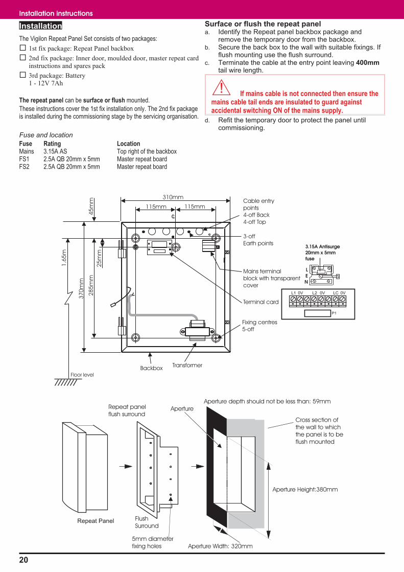
The Vigilon Repeat Panel Set consists of two packages:
� 1st fix package: Repeat Panel backbox
� 2nd fix package: Inner door, moulded door, master repeat cardinstructions and spares pack
� 3rd package: Battery1 - 12V 7Ah
The repeat panel can be surface or flush mounted.
These instructions cover the 1st fix installation only. The 2nd fix packageis installed during the commissioning stage by the servicing organisation.
Fuse and location
Fuse Rating LocationMains 3.15A AS Top right of the backboxFS1 2.5A QB 20mm x 5mm Master repeat boardFS2 2.5A QB 20mm x 5mm Master repeat board
Surface or flush the repeat panela. Identify the Repeat panel backbox package and
remove the temporary door from the backbox.b. Secure the back box to the wall with suitable fixings. If
flush mounting use the flush surround.c. Terminate the cable at the entry point leaving 400mm
tail wire length.
� If mains cable is not connected then ensure themains cable tail ends are insulated to guard againstaccidental switching ON of the mains supply.
d. Refit the temporary door to protect the panel untilcommissioning.
20
Installation instructions
cL
310mm
115mm115mm
37
0m
m
28
5m
m
25
mm
45
mm
Floor level
1.6
5m
BackboxTransformer
Mains terminal
block with transparent
cover
Terminal card
Fixing centres
5-off
Cable entry
points
4-off Back
4-off Top
3-off
Earth points
LEN
3.15A Antisurge20mm x 5mmfuse
P1
L1 0V L2 0V LC 0V
Repeat Panel
Cross section of
the wall to which
the panel is to be
flush mounted
Aperture
Flush
Surround
5mm diameter
fixing holes
Aperture Height:380mm
Aperture Width: 320mm
Aperture depth should not be less than: 59mmRepeat panel
flush surround
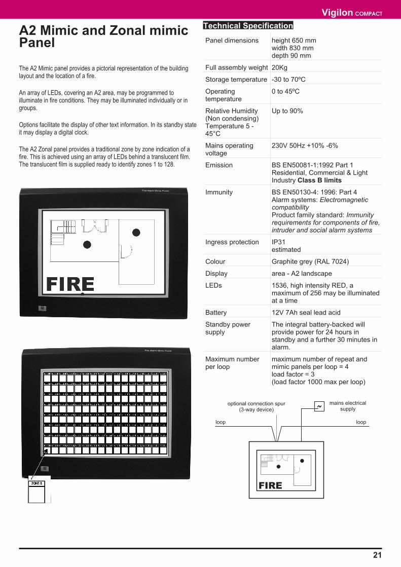
A2 Mimic and Zonal mimicPanel
The A2 Mimic panel provides a pictorial representation of the buildinglayout and the location of a fire.
An array of LEDs, covering an A2 area, may be programmed toilluminate in fire conditions. They may be illuminated individually or ingroups.
Options facilitate the display of other text information. In its standby stateit may display a digital clock.
The A2 Zonal panel provides a traditional zone by zone indication of afire. This is achieved using an array of LEDs behind a translucent film.The translucent film is supplied ready to identify zones 1 to 128.
Technical Specification
Panel dimensions height 650 mmwidth 830 mmdepth 90 mm
Full assembly weight 20Kg
Storage temperature -30 to 70ºC
Operatingtemperature
0 to 45ºC
Relative Humidity(Non condensing)Temperature 5 -45°C
Up to 90%
Mains operatingvoltage
230V 50Hz +10% -6%
Emission BS EN50081-1:1992 Part 1Residential, Commercial & LightIndustry Class B limits
Immunity BS EN50130-4: 1996: Part 4Alarm systems: ElectromagneticcompatibilityProduct family standard: Immunityrequirements for components of fire,intruder and social alarm systems
Ingress protection IP31estimated
Colour Graphite grey (RAL 7024)
Display area - A2 landscape
LEDs 1536, high intensity RED, amaximum of 256 may be illuminatedat a time
Battery 12V 7Ah seal lead acid
Standby powersupply
The integral battery-backed willprovide power for 24 hours instandby and a further 30 minutes inalarm.
Maximum numberper loop
maximum number of repeat andmimic panels per loop = 4load factor = 3(load factor 1000 max per loop)
21
Vigilon COMPACT
mains electricalsupply
optional connection spur(3-way device)
loop loop
FIRE
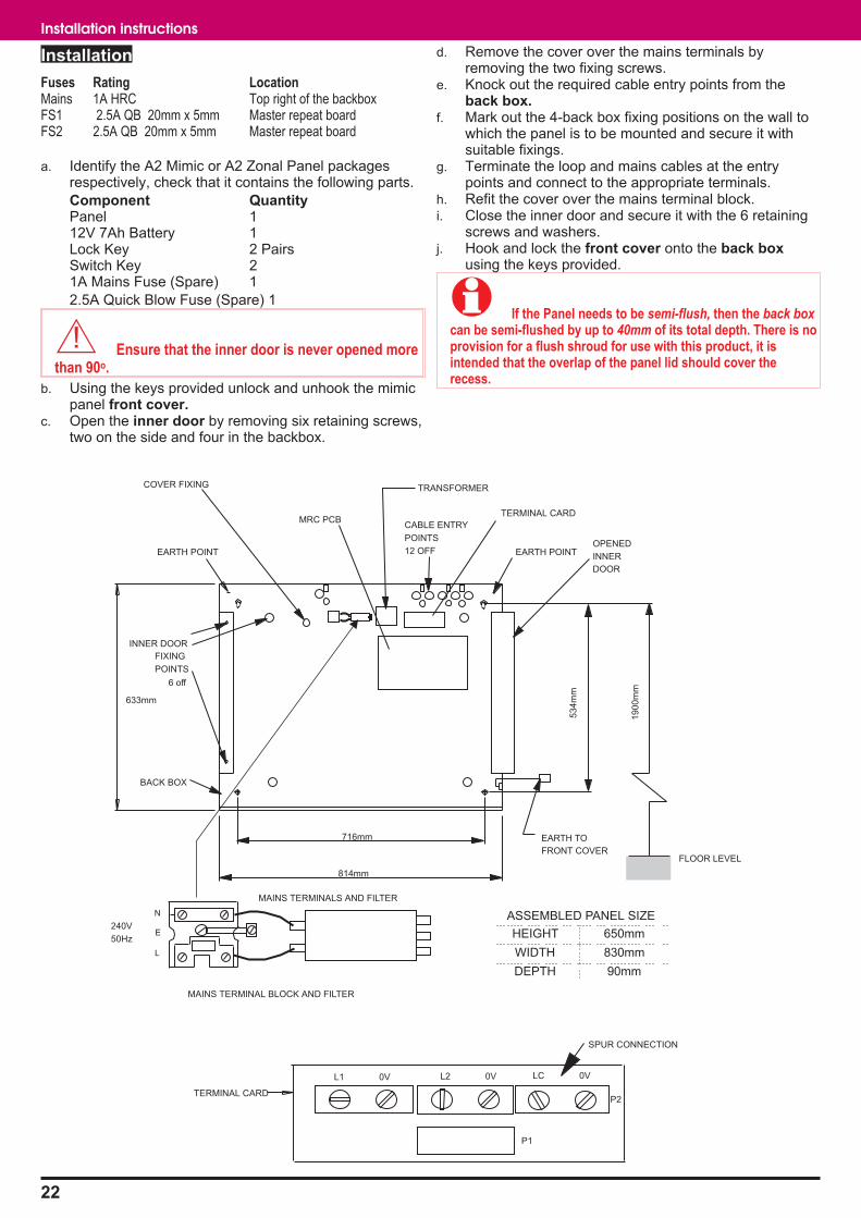
Installation
Fuses Rating LocationMains 1A HRC Top right of the backboxFS1 2.5A QB 20mm x 5mm Master repeat boardFS2 2.5A QB 20mm x 5mm Master repeat board
a. Identify the A2 Mimic or A2 Zonal Panel packagesrespectively, check that it contains the following parts.
Component QuantityPanel 112V 7Ah Battery 1Lock Key 2 PairsSwitch Key 21A Mains Fuse (Spare) 1
2.5A Quick Blow Fuse (Spare) 1
� Ensure that the inner door is never opened morethan 90o.
b. Using the keys provided unlock and unhook the mimicpanel front cover.
c. Open the inner door by removing six retaining screws,two on the side and four in the backbox.
d. Remove the cover over the mains terminals byremoving the two fixing screws.
e. Knock out the required cable entry points from theback box.
f. Mark out the 4-back box fixing positions on the wall towhich the panel is to be mounted and secure it withsuitable fixings.
g. Terminate the loop and mains cables at the entrypoints and connect to the appropriate terminals.
h. Refit the cover over the mains terminal block.i. Close the inner door and secure it with the 6 retaining
screws and washers.j. Hook and lock the front cover onto the back box
using the keys provided.
� If the Panel needs to be semi-flush, then the back boxcan be semi-flushed by up to 40mm of its total depth. There is noprovision for a flush shroud for use with this product, it isintended that the overlap of the panel lid should cover therecess.
22
Installation instructions
53
4m
m
814mm
EARTH POINT EARTH POINT
19
00
mm
FLOOR LEVEL
BACK BOX
716mm
FIXING
INNER DOOR
POINTS
EARTH TO
FRONT COVER
OPENED
INNER
DOOR
633mm
CABLE ENTRY
POINTS
12 OFF
MRC PCB
TERMINAL CARD
50Hz
240V
N
L
E
L1 0V
P1
LC 0V
P2
TRANSFORMERCOVER FIXING
SPUR CONNECTION
L2 0V
6 off
MAINS TERMINAL BLOCK AND FILTER
HEIGHT 650mm
WIDTH 830mm
DEPTH 90mm
ASSEMBLED PANEL SIZE
TERMINAL CARD
MAINS TERMINALS AND FILTER
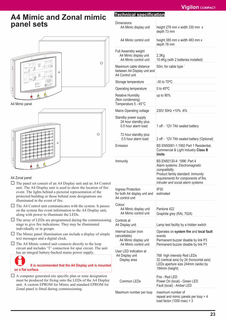
A4 Mimic and Zonal mimicpanel sets
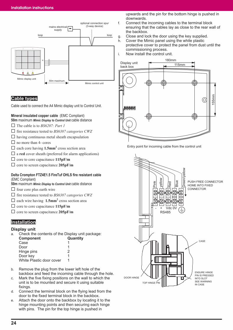
A4 Mimic panel
A4 Zonal panel
� The panel set consist of an A4 Display unit and an A4 Controlunit. The A4 Display unit is used to show the location of fireevent. The lights behind a pictorial representation of theprotected building or those behind zone designations areilluminated in the event of fire.
� The A4 Control unit communicates with the system. It passeson the system fire event information to the A4 Display unit,along with power to illuminate the LEDs.
� The array of LEDs are programmed during the commissioningstage to give fire indications. They may be illuminatedindividually or in groups.
� The Mimic panel illumination can include a display of simpletext messages and a digital clock.
� The A4 Mimic control unit connects directly to the loopcircuit and includes ‘T’ connection for spur circuit. The unithas an integral battery-backed mains power supply.
� It is recommended that the A4 Display unit is mountedon a flat surface.
� A computer generated site specific plan or zone designationmust be produced for fixing onto the LEDs of the A4 Displayunit. A custom EPROM for Mimic and standard EPROM forZonal panel is fitted during commissioning.
Technical specification
DimensionsA4 Mimic display unit
A4 Mimic control unit
height 276 mm x width 330 mm xdepth 73 mm
height 385 mm x width 483 mm xdepth 78 mm
Full Assembly weightA4 Mimic display unitA4 Mimic control unit
2.3Kg10.4Kg (with 2 batteries installed)
Maximum cable distancebetween A4 Display unit andA4 Control unit
50m, for cable type ’
Storage temperature -30 to 70ºC
Operating temperature 0 to 45ºC
Relative Humidity(Non condensing)Temperature 5 - 45°C
up to 90%
Mains Operating voltage 230V 50Hz +10% -6%
Standby power supply24 hour standby plus0.5 hour alarm load:
72 hour standby plus0.5 hour alarm load:
1 off - 12V 7Ah sealed battery
2 off - 12V 7Ah sealed battery (Optional)
Emission BS EN50081-1:1992 Part 1 Residential,Commercial & Light Industry Class Blimits
Immunity BS EN50130-4: 1996: Part 4Alarm systems: ElectromagneticcompatibilityProduct family standard: Immunityrequirements for components of fire,intruder and social alarm systems
Ingress Protectionfor both A4 display unit andA4 control unit
IP30estimated
ColourA4 Mimic display unitA4 Mimic control unit
Pantone 422
Graphite grey (RAL 7024)
Controls atA4 Display unit Lamp test facility by a hidden switch
Internal buzzer (noncancellable)
A4 Mimic display unitA4 Mimic control unit
Operates on system fire and local faulteventsPermanent buzzer disable by link P3Permanent buzzer disable by link P1
User LED indication atA4 Display unit
Display area
Common LEDs
768 high intensity Red LEDs32 (vertical axis) by 24 (horizontal axis)LEDs aperture size 244mm (wide) by184mm (height)
Fire - Red LEDPower On (local) - Green LEDFault (local) - Amber LED
Maximum number per loop maximum number ofrepeat and mimic panels per loop = 4load factor (1000 max) = 3
23
Vigilon COMPACT
COMPUTER
SUITERECEPTION
GROUND FLOOR
FIRST FLOOR
W.C. W.C.
W.C.
M.D.
PLANTROOM
CALL POINT
SENSOR
MAIN FIRE PANEL
MIMIC PANEL
VOID SENSOR
BOARD
ROOM
W.C.
ROOM
G1.
ROOM
G3.
ROOM
G4.
ROOM
F3.
PLANT
ROOM
ROOM
F4.
ROOM
G2.
ROOM
F1.
ROOM
F2.
GROUND
FLOOR
OPEN
OFFICE
FIRST
FLOOR
OPEN
OFFICE
G E N T
Fire PowerFault
ZONE 3
ZONE 4
ZONE 5
ZONE 6
ZONE 7
ZONE 8
ZONE 1
ZONE 2
ZONE 11
ZONE 12ZONE 13
ZONE 14ZONE 15
ZONE 16
ZONE 10
ZONE 9
ZONE 19ZONE 20
ZONE 21
ZONE 22ZONE 23
ZONE 24
ZONE 18
ZONE 17
ZONE 27ZONE 28
ZONE 29
ZONE 30ZONE 31
ZONE 32
ZONE 26
ZONE 25
ZONE 35ZONE 36
ZONE 37
ZONE 38ZONE 39
ZONE 40
ZONE 34
ZONE 33
ZONE 43ZONE 44
ZONE 45ZONE 46
ZONE 47ZONE 48
ZONE 42
ZONE 41
ZONE 51ZONE 52
ZONE 53
ZONE 54ZONE 55
ZONE 56
ZONE 50
ZONE 49
ZONE 59ZONE 60
ZONE 61
ZONE 62ZONE 63
ZONE 64
ZONE 58
ZONE 57
Cable types
Cable used to connect the A4 Mimic display unit to Control Unit.
Mineral insulated copper cable (EMC Compliant)50m maximum Mimic Display to Control Unit cable distance
� The cable is to BS6207: Part 1
� fire resistance tested to BS6387 categories CWZ
� having continuous metal sheath encapsulation
� no more than 4- cores
� each core having 1.5mm2 cross section area
� a red cover sheath (preferred for alarm applications)
� core to core capacitance 115pF/m
� core to screen capacitance 205pF/m
Delta Crompton FTZ4E1.5 FireTuf OHLS fire resistant cable(EMC Compliant)50m maximum Mimic Display to Control Unit cable distance
� four core plus earth wire
� fire resistance tested to BS6387 categories CWZ
� each wire having 1.5mm2 cross section area
� core to core capacitance 115pF/m
� core to screen capacitance 205pF/m
Installation
Display unita. Check the contents of the Display unit package:
Component QuantityCase 1Door 1Hinge pins 2Door key 1White Plastic door cover 1
b. Remove the plug from the lower left hole of thebackbox and feed the incoming cable through the hole.
c. Mark the five fixing positions on the wall to which theunit is to be mounted and secure it using suitablefixings.
d. Connect the terminal block on the flying lead from thedoor to the fixed terminal block in the backbox.
e. Attach the door onto the backbox by locating it to thehinge mounting points and then securing each hingewith pins. The pin for the top hinge is pushed in
upwards and the pin for the bottom hinge is pushed indownwards.
f. Connect the incoming cables to the terminal blockensuring that the cables lay as close to the rear wall ofthe backbox.
g. Close and lock the door using the key supplied.h. Cover the Mimic panel using the white plastic
protective cover to protect the panel from dust until thecommissioning process.
i. Now install the control unit.
24
Installation instructions
-
PUSH FREE CONNECTOR
HOME INTO FIXED
CONNECTOR
CASE
DOOR HINGE
TOP HINGE PIN
ENSURE HINGE
PIN IS PRESSED
INTO SLOT
SEE WARNING
IN CASE
Entry point for incoming cable from the control unit
115mmDisplay unitback box
155m
m
Gre
en/y
ello
w
Blu
e
Red
yello
w
Pin
k
- + Vdc 0V
RS485
180mm
mains electricalsupply
optional connection spur(3-way device)
loop loop
50m maximum
Fire Power Fault
Mimic display unit
Mimic control unit
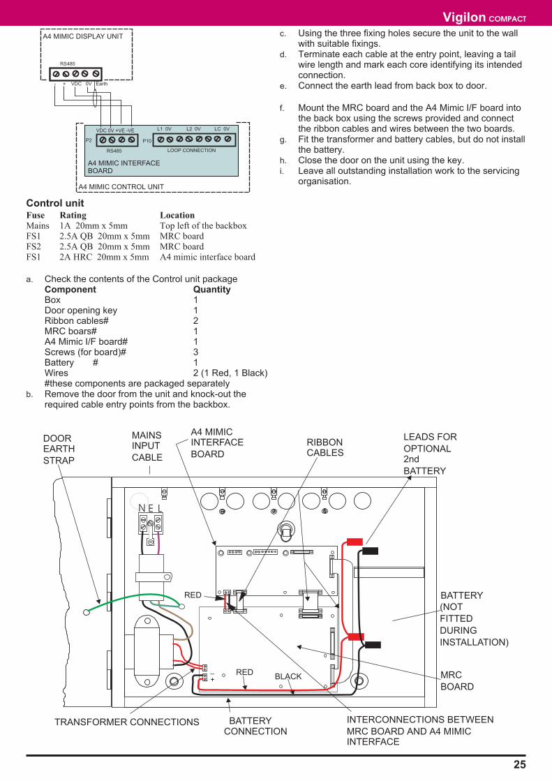
Control unitFuse Rating Location
Mains 1A 20mm x 5mm Top left of the backboxFS1 2.5A QB 20mm x 5mm MRC boardFS2 2.5A QB 20mm x 5mm MRC boardFS1 2A HRC 20mm x 5mm A4 mimic interface board
a. Check the contents of the Control unit packageComponent QuantityBox 1Door opening key 1Ribbon cables# 2MRC boars# 1A4 Mimic I/F board# 1Screws (for board)# 3Battery # 1Wires 2 (1 Red, 1 Black)#these components are packaged separately
b. Remove the door from the unit and knock-out therequired cable entry points from the backbox.
c. Using the three fixing holes secure the unit to the wallwith suitable fixings.
d. Terminate each cable at the entry point, leaving a tailwire length and mark each core identifying its intendedconnection.
e. Connect the earth lead from back box to door.
f. Mount the MRC board and the A4 Mimic I/F board intothe back box using the screws provided and connectthe ribbon cables and wires between the two boards.
g. Fit the transformer and battery cables, but do not installthe battery.
h. Close the door on the unit using the key.i. Leave all outstanding installation work to the servicing
organisation.
25
Vigilon COMPACT
DOOREARTH
STRAP
MAINSINPUT
CABLE
A4 MIMICINTERFACE
BOARD
RIBBONCABLES
TRANSFORMER CONNECTIONS BATTERYCONNECTION
MRC
BOARD
BATTERY
(NOT
FITTED
DURING
INSTALLATION)
INTERCONNECTIONS BETWEEN
MRC BOARD AND A4 MIMICINTERFACE
LEADS FOR
OPTIONAL2nd
BATTERY
_
+RED
BLACK
RED
E LN
A4 MIMIC DISPLAY UNIT
- + VDC 0V Earth
RS485
A4 MIMIC INTERFACEBOARD
P2
VDC 0V +VE -VE
P10
L1 0V L2 0V LC 0V
RS485 LOOP CONNECTION
A4 MIMIC CONTROL UNIT
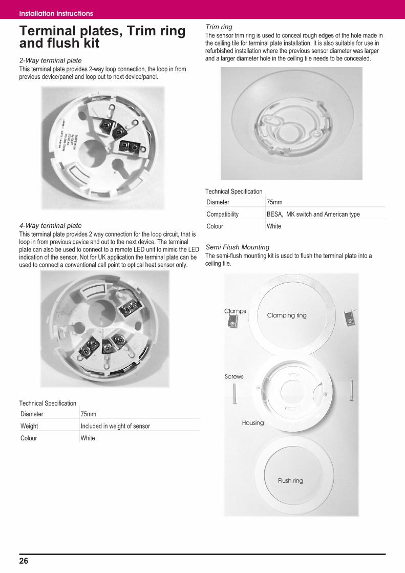
Terminal plates, Trim ringand flush kit2-Way terminal plate
This terminal plate provides 2-way loop connection, the loop in fromprevious device/panel and loop out to next device/panel.
4-Way terminal plate
This terminal plate provides 2 way connection for the loop circuit, that isloop in from previous device and out to the next device. The terminalplate can also be used to connect to a remote LED unit to mimic the LEDindication of the sensor. Not for UK application the terminal plate can beused to connect a conventional call point to optical heat sensor only.
Technical Specification
Diameter 75mm
Weight Included in weight of sensor
Colour White
Trim ring
The sensor trim ring is used to conceal rough edges of the hole made inthe ceiling tile for terminal plate installation. It is also suitable for use inrefurbished installation where the previous sensor diameter was largerand a larger diameter hole in the ceiling tile needs to be concealed.
Technical Specification
Diameter 75mm
Compatibility BESA, MK switch and American type
Colour White
Semi Flush Mounting
The semi-flush mounting kit is used to flush the terminal plate into aceiling tile.
26
Installation instructions
Housing
Flush ring
Clamping ringClamps
Screws
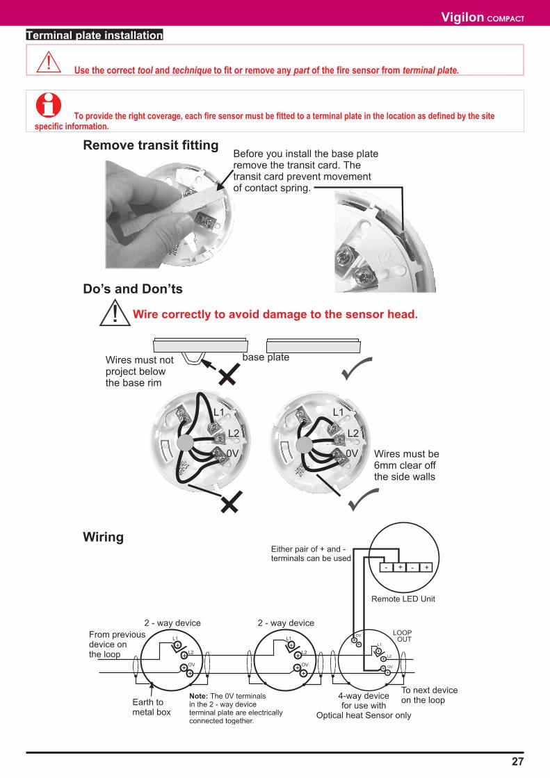
Terminal plate installation
� Use the correct tool and technique to fit or remove any part of the fire sensor from terminal plate.
� To provide the right coverage, each fire sensor must be fitted to a terminal plate in the location as defined by the sitespecific information.
27
Vigilon COMPACT
++
+
+
L1
L2
OV
LOOPOUT
4-way devicefor use with
Optical heat Sensor only
++
OV
Remote LED Unit
- + - +
Either pair of + and -terminals can be used
Wires must be6mm clear offthe side walls
Wires must notproject belowthe base rim
base plate
Before you install the base plateremove the transit card. Thetransit card prevent movementof contact spring.
L1
L2
0V
L1
L2
0V
++
+
+L1
L2
OV
2 - way device
Earth tometal box
++
+
+L1
L2
OV
From previousdevice onthe loop
Note: The 0V terminalsin the 2 - way deviceterminal plate are electricallyconnected together.
To next deviceon the loop
2 - way device
Do’s and Don’ts
Remove transit fitting
Wiring
Wire correctly to avoid damage to the sensor head.
Trim ring installation
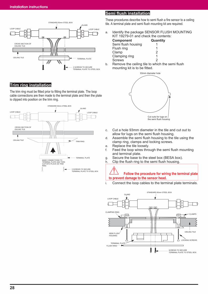
The trim ring must be fitted prior to fitting the terminal plate. The loopcable connections are then made to the terminal plate and then the plateis clipped into position on the trim ring.
Semi flush installation
These procedures describe how to semi flush a fire sensor to a ceilingtile. A terminal plate and semi flush mounting kit are required.
a. Identify the package SENSOR FLUSH MOUNTINGKIT 19279-01 and check the contents:
Component QuantitySemi flush housing 1Flush ring 1Clamp 2Clamping ring 1Screws 2
b. Remove the ceiling tile to which the semi flushmounting kit is to be fitted.
c. Cut a hole 93mm diameter in the tile and cut out toallow for lugs on the semi flush housing.
d. Assemble the semi flush housing to the tile using theclamp ring, clamps and locking screws.
e. Replace the tile loosely.f. Feed the loop wires through the semi flush mounting
and terminal plate.g. Secure the base to the steel box (BESA box).h. Clip the flush ring to the semi flush housing.
� Follow the procedure for wiring the terminal plateto prevent damage to the sensor head.
i. Connect the loop cables to the terminal plate terminals.
28
Installation instructions
LOOP CABLE
STANDARD 60mm STEEL BOX
GLAND
LOOP CABLE
TRIM RING
TERMINAL PLATE
MAKE CONNECTIONS TOTERMINAL PLATE AND THENCLIP INTO PLACE ON TRIMRING
CEILING TILE
2 SCREWS TO SECURE
TERMINAL PLATE TO STEEL BOX
CROSS SECTION OF
CEILING TILE
93mm diameter hole
Cut outs for lugs onthe semi flush housing
LOOP CABLE
STANDARD 60mm STEEL BOX
GLAND
CLAMPING RING
CEILING TILESEMI FLUSH
HOUSING
LOCKING SCREWS
TERMINAL PLATE
FLUSH RING
SCREWS TO SECURE
TERMINAL PLATE TO STEEL BOX
CLAMPS
LOOP CABLE
STANDARD 60mm STEEL BOX
GLAND
LOOP CABLE
TERMINAL PLATECEILING TILE
2 SCREWS TO SECURE
TERMINAL PLATE TO STEEL BOX
CROSS SECTION OF
CEILING TILE
Fire sensors
� To prevent dirt and dust in the environmentdegrading the performance of the fire sensors, the sensorhead installation should be carried out by the installer justprior to the commissioning of the system.
� To prevent damage to a fire sensor, the correcttool and technique must be used when removing or fittingsensor, or its sub assembly, to and from the terminal plate.
� Optical sensor - COMPACT-O
� Optical heat sensor - OH
� Heat sensor - H
� Optical heat sensor sounder - OHS
� Heat sensor sounder - HS
� Optical heat sensor with remote LED
� Optical heat sensor with monitored line MCP (not for UK use)
� Damage will occur if undue force is used onfitting or removal of any part of a sensor assembly.
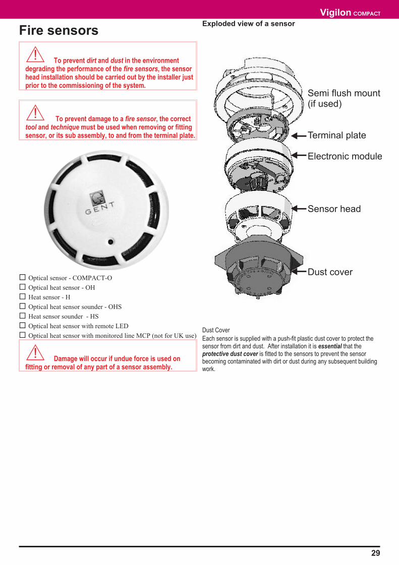
Exploded view of a sensor
Dust Cover
Each sensor is supplied with a push-fit plastic dust cover to protect thesensor from dirt and dust. After installation it is essential that theprotective dust cover is fitted to the sensors to prevent the sensorbecoming contaminated with dirt or dust during any subsequent buildingwork.
29
Vigilon COMPACT
Semi flush mount(if used)
Terminal plate
Electronic module
Sensor head
Dust cover

Optical Sensor
StandardSmoke BS5445:Part 7 (EN54 : Part 7)
Dimensions diameter 86 mmheight 60 mm (with terminal plate)
Full assembly weight 580g with terminal plate
Storage temperature -30 to 70ºC
Operatingtemperature
0 to 50°C
Relative Humidity(Non condensing)Temperature 5 -45°C
up to 90%
Emission BS EN50081-1:1992 Part 1Residential, Commercial & LightIndustry Class B limits
Immunity BS EN50130-4: 1996: Part 4Alarm systems: ElectromagneticcompatibilityProduct family standard: Immunityrequirements for components offire, intruder and social alarmsystems
Ingress Protection IP30 estimated - when mountedon a flat ceilingIP20 estimated when mounted ona BESA box
Air flow in installedenvironment
10m/s gusting for up to30 minutes
5m/s continuous
Vibration 5 to 60Hz
Colour White
Operating voltage 20-50V
Indicators Red LED visible at 500LUXambient light levels 3m
Mounting Surface or Semi-flush, usingmounting kit (model no 19279-01)
Chamber format Sensing chamber is removable
Loop Maximum number per loop = 200Load (1000 max) = 1
Optical Heat Sensor
StandardHeatSmoke
BS5445:Part 5 (EN54 : Part 5)BS5445:Part 7 (EN54 : Part 7
Dimensions diameter 86 mmheight 60 mm (with terminal plate)
Full Assembly weight 580g with terminal plate
Storage temperature -30 to 70ºC
Operatingtemperature
0 to 50°C (If only heat is usedthen 0 to 45°C)
Relative Humidity(Non condensing)Temperature 5 -45°C
up to 90%
Emission BS EN50081-1:1992 Part 1Residential, Commercial & LightIndustry Class B limits
Immunity BS EN50130-4: 1996: Part 4Alarm systems: ElectromagneticcompatibilityProduct family standard: Immunityrequirements for components offire, intruder and social alarmsystems
Ingress Protection IP30 estimated when mounted ona flat ceilingIP20 estimated when mounted ona BESA box
Air flow in installedenvironment
10m/s gusting for up to 30minutes5m/s continuous
Vibration 5 to 60Hz
Colour White
Operating voltage 20-50V
Indicators Red LED visible at 500LUXambient light levels 3m
Mounting Surface or Semi-flush, usingmounting kit (model no 19279-01)
Chamber format Sensing chamber is removable
Loop Maximum number per loop = 200Load (1000 max) = 1
30
Installation instructions

Optical Heat Sounder
StandardHeat detectionSmoke detectionSounder
BS5445: Parts 5 (EN54 : Part 5)BS5445 : Part 7 (EN54 : Part 7)BS5839 : Part 1 Sound output85dBA at 1m
Dimensions diameter 86 mmheight 60 mm (with terminal plate)
Full Assembly weight 600g with terminal plate
Storage temperature -30 to 70ºC
Operatingtemperature
0 to 50°C (If heat is used then 0 to45°C)
Relative Humidity(Non condensing)Temperature 5 -45°C
up to 90%
Emission BS EN50081-1:1992 Part 1Residential, Commercial & LightIndustry Class B limits
Immunity BS EN50130-4: 1996: Part 4Alarm systems: ElectromagneticcompatibilityProduct family standard: Immunityrequirements for components offire, intruder and social alarmsystems
Ingress Protection IP30 estimated when mounted ona flat ceilingIP20 estimated when mounted ona BESA box
Air flow in installedenvironment
10m/s gusting for up to 30minutes5m/s continuous
Vibration 5 to 60Hz
Colour White
Operating voltage 20-50V
Indicators Red LED visible at 500LUXambient light levels 3m
Mounting Surface or Semi-flush usingmounting kit (model no 19279-01)
Chamber format Sensing chamber is removable
Loop Maximum number per loop = 125Load (1000 max) = 8
Heat Sensor
StandardHeat BS5445:Part 5 (EN54 : Part 5)
BS5445:Part 8 (EN54 : Part 8)
Dimensionsstandard
environmentallyprotected
diameter 86 mmheight 60 mm (with terminal plate)
180 mm height (the probeprotrudes 100mm)180 mm width90 mm depth
Full Assembly weight 505g with terminal plate
Storage temperature -30 to 70ºC
Operatingtemperature
0 to 45°C (Exception is when setto operate at State 5 or 6, Stateinfirmation is available in thecommissioning manua)
Relative Humidity(Non condensing)Temperature5 - 45°C
up to 90%
Emission BS EN50081-1:1992 Part 1Residential, Commercial & LightIndustry Class B limits
Immunity BS EN50130-4: 1996: Part 4Alarm systems: ElectromagneticcompatibilityProduct family standard: Immunityrequirements for components offire, intruder and social alarmsystems
Ingress Protection IP20 estimated - standard productIP55 environmentally protectedversion
Air flow in installedenvironment
10m/s gusting for up to 30minutes5m/s continuous
Vibration 5 to 60Hz
Colour White
Operating voltage 20-50V
Indicators Red LED visible at 500LUXambient light levels 3m
Mounting Surface or Semi-flush usingmounting kit (model no 19279-01)
Chamber format Sensing chamber is removable
Loop Maximum number per loop = 200Load (1000 max) = 1
31
Vigilon COMPACT
Heat Sounder
StandardHeat detectionSounder
BS5445: Parts 5 (EN54 : Part 5)BS5839 : Part 1 Sound output85dBA at 1m
Dimensions diameter 86 mmheight 60 mm (with terminal plate)
Full Assembly weight 600g with terminal plate
Storage temperature -30 to 70ºC
Operatingtemperature
0 to 50°C
Relative Humidity(Non condensing)Temperature5 - 45°C
up to 90%
Emission BS EN50081-1:1992 Part 1Residential, Commercial & LightIndustry Class B limits
Immunity BS EN50130-4: 1996: Part 4Alarm systems: ElectromagneticcompatibilityProduct family standard: Immunityrequirements for components offire, intruder and social alarmsystems
Ingress Protection IP30 estimated (mounted on a flatceiling)IP20 estimated (mounted on aBESA box)
Air flow in installedenvironment
10m/s gusting for up to 30minutes5m/s continuous
Vibration 5 to 60Hz
Colour White
Operating voltage 20-50V
Indicators Red LED visible at 500LUXambient light levels 3m
Mounting Surface or Semi-flush usingmounting kit (model no 19279-01)
Chamber format Sensing chamber is removable
Loop Maximum number per loop = 125Load (1000 max) = 8
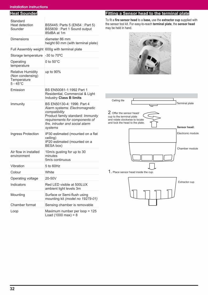
Fitting a Sensor head to the terminal plate
To fit a fire sensor head to a base, use the extractor cup supplied withthe sensor tool kit. For easy-to-reach terminal plate, the sensor headmay be held in hand.
32
Installation instructions
Terminal plate
Sensor head:
Electronic module
Chamber module
Extractor cup
Ceiling tile
1. Place sensor head inside the cup.
2. Offer the sensor head/
cup to the terminal plateand rotate clockwise to locateand lock the head to the plate.
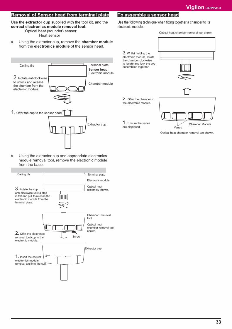
Removal of Sensor head from terminal plate
Use the extractor cup supplied with the tool kit, and thecorrect electronics module removal tool:
Optical heat (sounder) sensorHeat sensor
a. Using the extractor cup, remove the chamber modulefrom the electronics module of the sensor head.
b. Using the extractor cup and appropriate electronicsmodule removal tool, remove the electronic modulefrom the base.
To assemble a sensor head
Use the following technique when fitting together a chamber to itselectronic module.
33
Vigilon COMPACT
Ceiling tile Terminal plate
Sensor head:Electronic module
Chamber module
Extractor cup
1. Offer the cup to the sensor head.
2. Rotate anticlockwise
to unlock and releasethe chamber from theelectronic module.
T
Terminal plate
Electronic module
Optical heatassembly shown.
Extractor cup
Ceiling tile
2. Offer the electronics
removal tool/cup to theelectronic module.
3. Rotate the cup
anti-clockwise until a stopis felt and pull to release theelectronic module from theterminal plate.
Screw
Chamber Removaltool
Optical heatchamber removal toolshown.
1. Insert the correct
electronics moduleremoval tool into the cup.
2. Offer the chamber to
the electronic module.
3. Whilst holding the
electronic module, rotatethe chamber clockwiseto locate and lock the twoassemblies together.
Chamber Module1. Ensure the vanes
are displaced
Optical heat chamber removal tool shown.
Optical heat chamber removal too shown.
Vanes
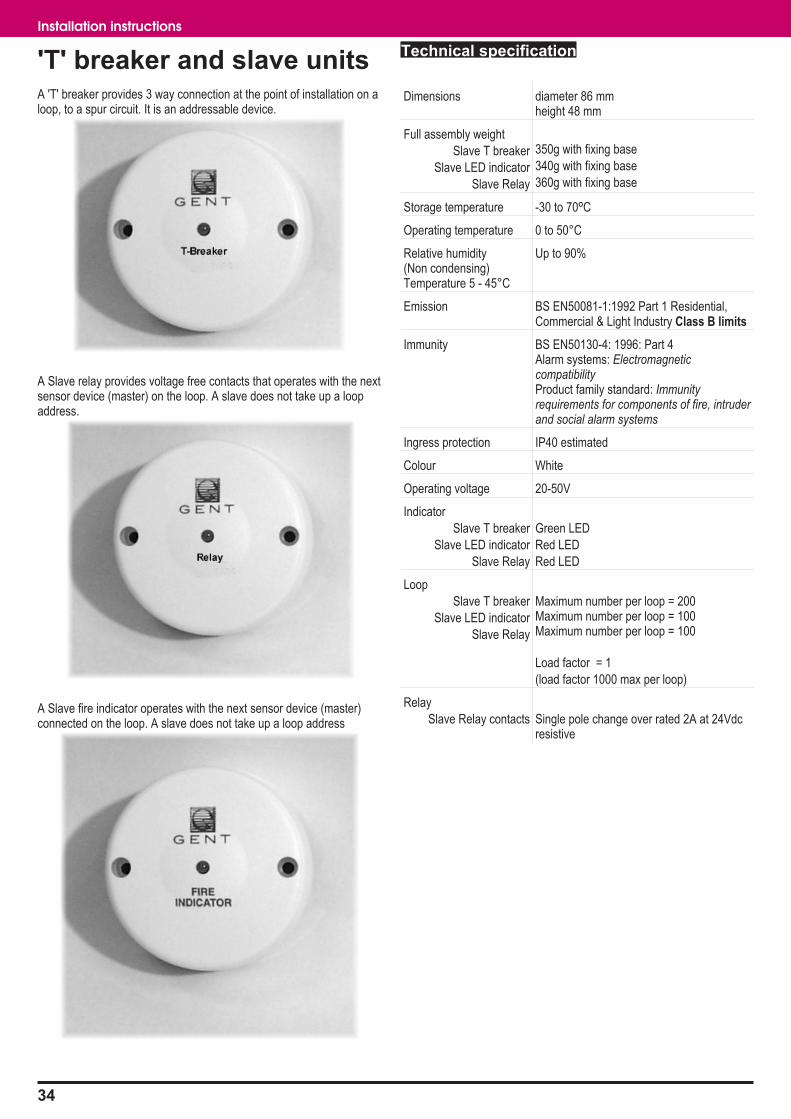
'T' breaker and slave unitsA 'T' breaker provides 3 way connection at the point of installation on aloop, to a spur circuit. It is an addressable device.
A Slave relay provides voltage free contacts that operates with the nextsensor device (master) on the loop. A slave does not take up a loopaddress.
A Slave fire indicator operates with the next sensor device (master)connected on the loop. A slave does not take up a loop address
Technical specification
Dimensions diameter 86 mmheight 48 mm
Full assembly weight
Slave T breaker
Slave LED indicator
Slave Relay
350g with fixing base
340g with fixing base
360g with fixing base
Storage temperature -30 to 70ºC
Operating temperature 0 to 50°C
Relative humidity(Non condensing)Temperature 5 - 45°C
Up to 90%
Emission BS EN50081-1:1992 Part 1 Residential,Commercial & Light Industry Class B limits
Immunity BS EN50130-4: 1996: Part 4Alarm systems: ElectromagneticcompatibilityProduct family standard: Immunityrequirements for components of fire, intruderand social alarm systems
Ingress protection IP40 estimated
Colour White
Operating voltage 20-50V
Indicator
Slave T breaker
Slave LED indicator
Slave Relay
Green LED
Red LED
Red LED
Loop
Slave T breaker
Slave LED indicator
Slave Relay
Maximum number per loop = 200Maximum number per loop = 100Maximum number per loop = 100
Load factor = 1
(load factor 1000 max per loop)
Relay
Slave Relay contacts Single pole change over rated 2A at 24Vdcresistive
34
Installation instructions
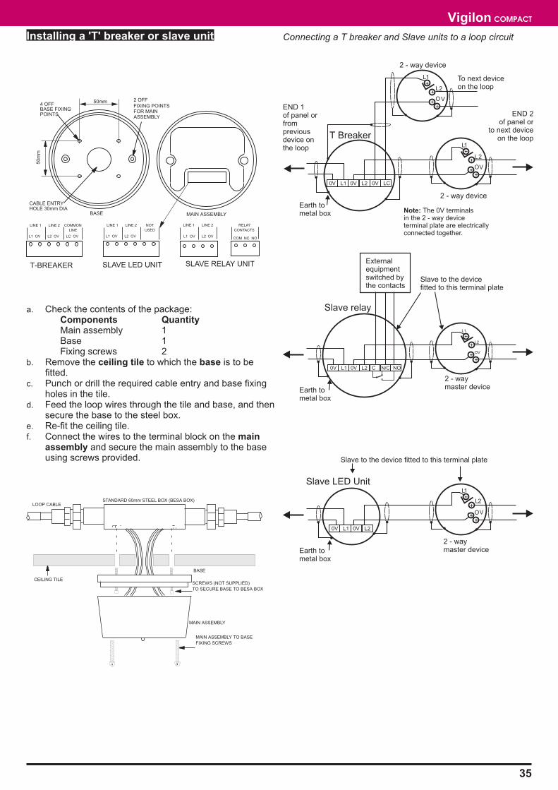
Installing a 'T' breaker or slave unit
a. Check the contents of the package:Components QuantityMain assembly 1Base 1Fixing screws 2
b. Remove the ceiling tile to which the base is to befitted.
c. Punch or drill the required cable entry and base fixingholes in the tile.
d. Feed the loop wires through the tile and base, and thensecure the base to the steel box.
e. Re-fit the ceiling tile.f. Connect the wires to the terminal block on the main
assembly and secure the main assembly to the baseusing screws provided.
Connecting a T breaker and Slave units to a loop circuit
35
Vigilon COMPACT
50mm
50m
m
CABLE ENTRYHOLE 30mm DIA
4 OFFBASE FIXINGPOINTS
2 OFF
FIXING POINTSFOR MAINASSEMBLY
BASE MAIN ASSEMBLY
L1 OV L2 OV LC OV
LINE 1 LINE 2 COMMON
LINE
T-BREAKER
L1 OV L2 OV
LINE 1 LINE 2 NOT
USED
SLAVE LED UNIT
L1 OV L2 OV
LINE 1 LINE 2 RELAY
CONTACTS
COM NC NO
SLAVE RELAY UNIT
BASE
CEILING TILESCREWS (NOT SUPPLIED)
TO SECURE BASE TO BESA BOX
MAIN ASSEMBLY
MAIN ASSEMBLY TO BASE
FIXING SCREWS
LOOP CABLESTANDARD 60mm STEEL BOX (BESA BOX)
Earth tometal box
++
+
+L1
L2
OV
END 1of panel orfrompreviousdevice onthe loop
END 2of panel or
to next deviceon the loop
2 - way device
0V L1 0V L2 0V LC
++
+
+L1
L2
OV
To next deviceon the loop
2 - way device
Earth tometal box
++
+
+L1
L2
OV
2 - waymaster device
0V L1 0V L2 C N/C NO
Externalequipmentswitched bythe contacts
Earth tometal box
++
+
+L1
L2
OV
Note: The 0V terminalsin the 2 - way deviceterminal plate are electricallyconnected together.
2 - waymaster device
0V L1 0V L2
Slave to the device fitted to this terminal plate
T Breaker
Slave relay
Slave to the devicefitted to this terminal plate
Slave LED Unit
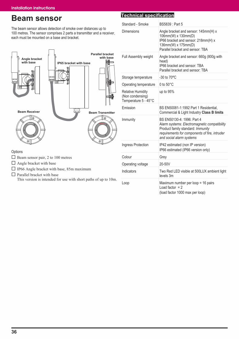
Beam sensorThe beam sensor allows detection of smoke over distances up to100 metres. The sensor comprises 2 parts a transmitter and a receiver,each must be mounted on a base and bracket.
Options
� Beam sensor pair, 2 to 100 metres
� Angle bracket with base
� IP66 Angle bracket with base, 85m maximum
� Parallel bracket with baseThis version is intended for use with short paths of up to 10m.
Technical specification
Standard - Smoke BS5839 : Part 5
Dimensions Angle bracket and sensor: 145mm(H) x106mm(W) x 130mm(D)IP66 bracket and sensor: 218mm(H) x136mm(W) x 175mm(D)Parallel bracket and sensor: TBA
Full Assembly weight Angle bracket and sensor: 660g (800g withhead)IP66 bracket and sensor: TBAParallel bracket and sensor: TBA
Storage temperature -30 to 70ºC
Operating temperature 0 to 50°C
Relative Humidity(Non condensing)Temperature 5 - 45°C
up to 95%
Emission BS EN50081-1:1992 Part 1 Residential,Commercial & Light Industry Class B limits
Immunity BS EN50130-4: 1996: Part 4Alarm systems: Electromagnetic compatibilityProduct family standard: Immunityrequirements for components of fire, intruderand social alarm systems
Ingress Protection IP42 estimated (non IP version)
IP66 estimated (IP66 version only)
Colour Grey
Operating voltage 20-50V
Indicators Two Red LED visible at 500LUX ambient lightlevels 3m
Loop Maximum number per loop = 16 pairsLoad factor = 2
(load factor 1000 max per loop)
36
Installation instructions
Beam Receiver Beam Transmitter
Beam TxBeam Rx
Angle bracketwith base IP65 bracket with base
Parallel bracketwith base
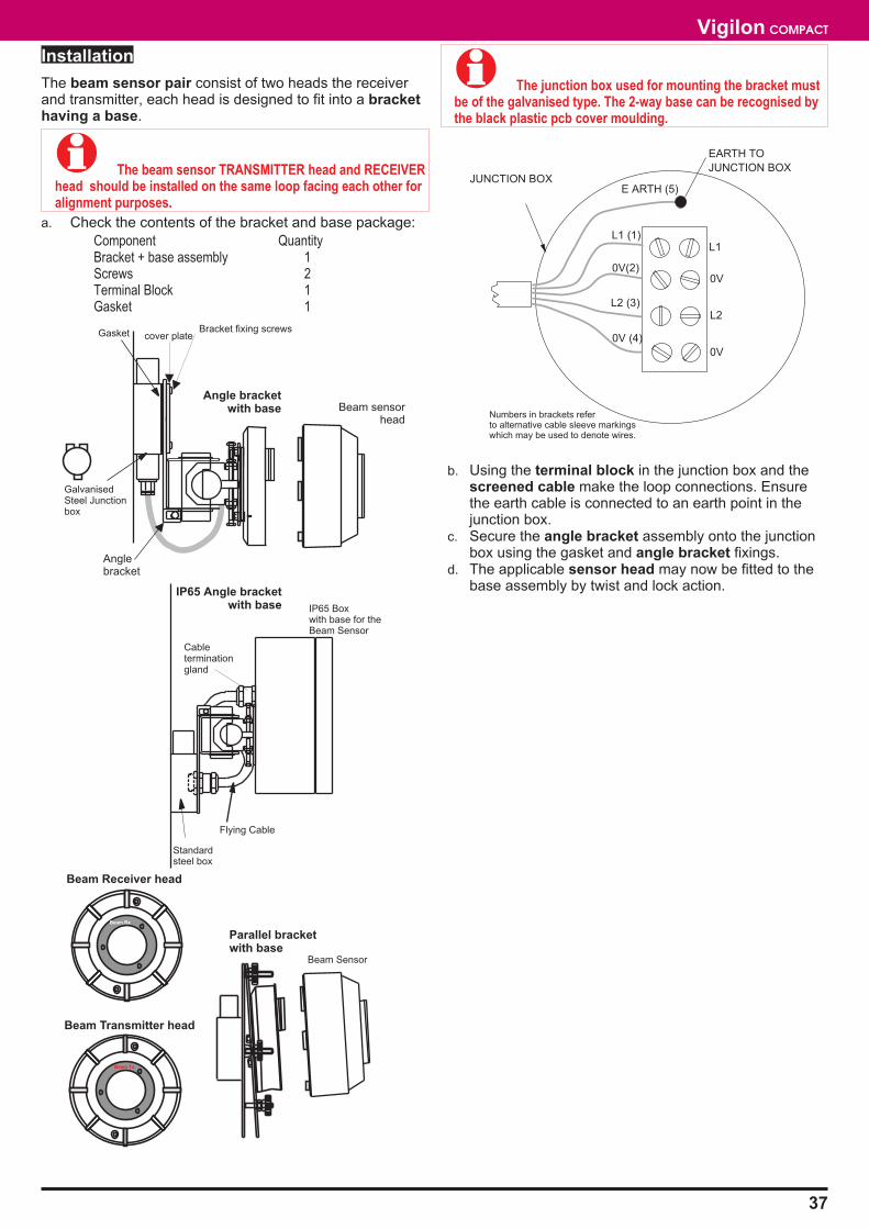
Installation
The beam sensor pair consist of two heads the receiverand transmitter, each head is designed to fit into a brackethaving a base.
� The beam sensor TRANSMITTER head and RECEIVERhead should be installed on the same loop facing each other foralignment purposes.
a. Check the contents of the bracket and base package:
Component QuantityBracket + base assembly 1Screws 2Terminal Block 1Gasket 1
� The junction box used for mounting the bracket mustbe of the galvanised type. The 2-way base can be recognised bythe black plastic pcb cover moulding.
b. Using the terminal block in the junction box and thescreened cable make the loop connections. Ensurethe earth cable is connected to an earth point in thejunction box.
c. Secure the angle bracket assembly onto the junctionbox using the gasket and angle bracket fixings.
d. The applicable sensor head may now be fitted to thebase assembly by twist and lock action.
37
Vigilon COMPACT
Beam Transmitter head
Beam Tx
Beam Receiver head
Beam Rx
Cableterminationgland
Standardsteel box
Bracket fixing screwscover plate
GalvanisedSteel Junctionbox
Anglebracket
Gasket
Beam sensorhead
Parallel bracketwith base
Beam Sensor
IP65 Angle bracketwith base
Angle bracketwith base
Flying Cable
IP65 Boxwith base for theBeam Sensor
JUNCTION BOX
EARTH TO
JUNCTION BOX
L1
0V
L2
0V
L1 (1)
0V (4)
0V(2)
L2 (3)
E ARTH (5)
Numbers in brackets referto alternative cable sleeve markingswhich may be used to denote wires.
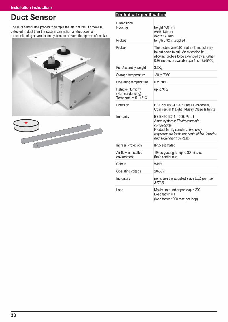
Duct SensorThe duct sensor use probes to sample the air in ducts. If smoke isdetected in duct then the system can action a shut-down ofair-conditioning or ventilation system to prevent the spread of smoke.
Technical specification
DimensionsHousing
Probes
height 160 mmwidth 180mmdepth 170mmlength 0.92m supplied
Probes The probes are 0.92 metres long, but maybe cut down to suit. An extension kitallowing probes to be extended by a further0.92 metres is available (part no 17908-06)
Full Assembly weight 3.3Kg
Storage temperature -30 to 70ºC
Operating temperature 0 to 50°C
Relative Humidity(Non condensing)Temperature 5 - 45°C
up to 90%
Emission BS EN50081-1:1992 Part 1 Residential,Commercial & Light Industry Class B limits
Immunity BS EN50130-4: 1996: Part 4Alarm systems: ElectromagneticcompatibilityProduct family standard: Immunityrequirements for components of fire, intruderand social alarm systems
Ingress Protection IP55 estimated
Air flow in installedenvironment
10m/s gusting for up to 30 minutes5m/s continuous
Colour White
Operating voltage 20-50V
Indicators none, use the supplied slave LED (part no34702)
Loop Maximum number per loop = 200Load factor = 1
(load factor 1000 max per loop)
38
Installation instructions
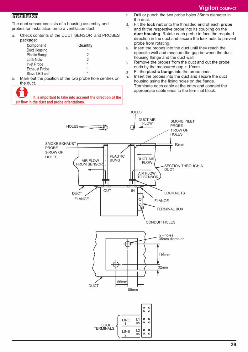
Installation
The duct sensor consists of a housing assembly andprobes for installation on to a ventilation duct.
a. Check contents of the DUCT SENSOR and PROBESpackage:
Component QuantityDuct Housing 1Plastic Bungs 2Lock Nuts 2Inlet Probe 1Exhaust Probe 1Slave LED unit 1
b. Mark out the position of the two probe hole centres onthe duct.
� It is important to take into account the direction of theair flow in the duct and probe orientations.
c. Drill or punch the two probe holes 35mm diameter inthe duct.
d. Fit the lock nut onto the threaded end of each probeand fit the respective probe into its coupling on theduct housing. Rotate each probe to face the requireddirection in the duct and secure the lock nuts to preventprobe from rotating.
e. Insert the probes into the duct until they reach theopposite wall and measure the gap between the ducthousing flange and the duct wall.
f. Remove the probes from the duct and cut the probeends by the measured gap + 10mm.
g. Fit the plastic bungs into the probe ends.h. Insert the probes into the duct and secure the duct
housing using the fixing holes on the flange.i. Terminate each cable at the entry and connect the
appropriate cable ends to the terminal block.
39
Vigilon COMPACT
DUCT AIRFLOW
AIR FLOWTO SENSOR
AIR FLOWFROM SENSOR
PLASTICBUNG
SECTION THROUGH ADUCT
LOCK NUTS
FLANGE
TERMINAL BOX
CONDUIT HOLES
PROBE
1 ROW OFHOLES
SMOKE INLET
SMOKE EXHAUSTPROBE
3-ROW OF
HOLES
DUCT
FLANGE
OUT IN
10mm
66mm
55mm
32mm
116mm
DUCT
2 - holes35mm diameter
L10V
L20V
LINE
LINE2
1
TERMINALSLOOP
DUCT AIRFLOW
HOLES
HOLES
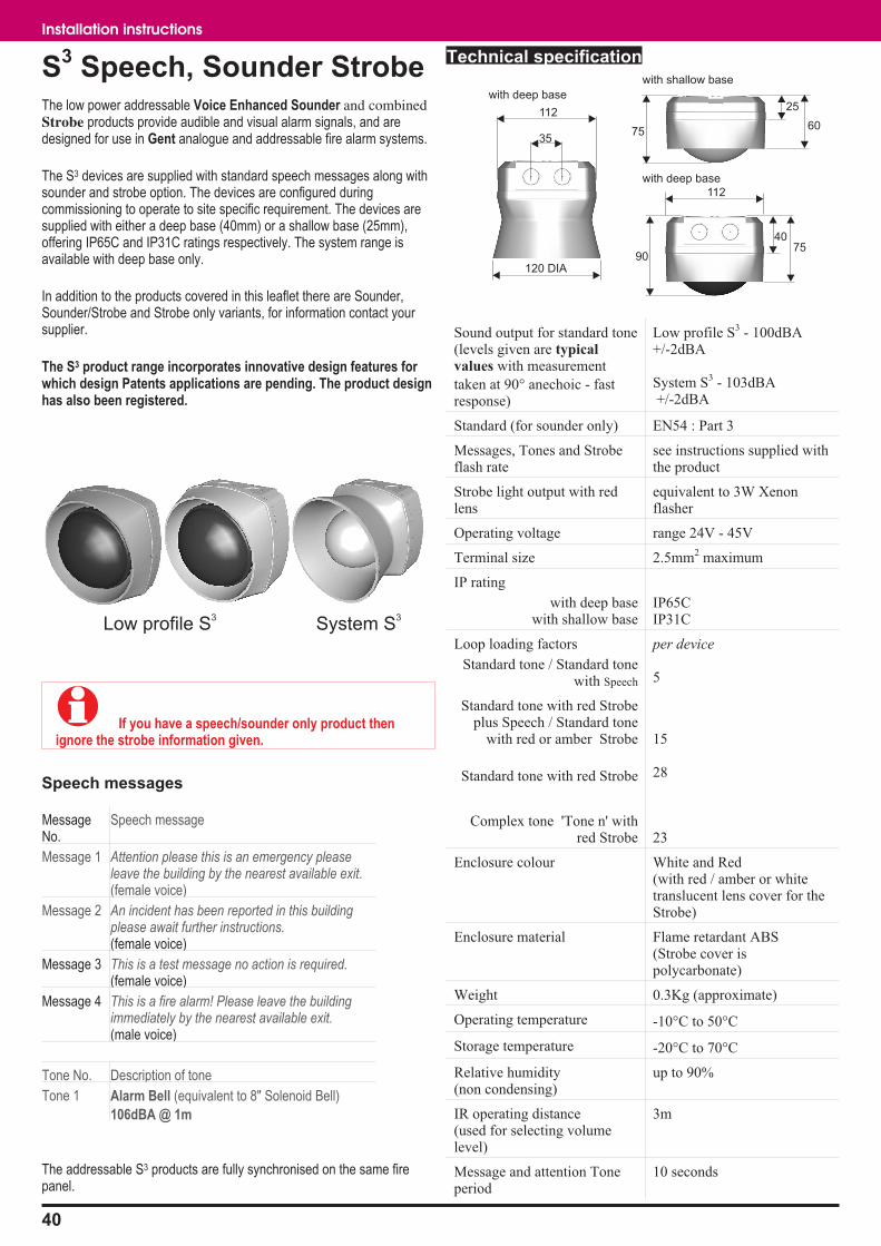
S3
Speech, Sounder StrobeThe low power addressable Voice Enhanced Sounder and combinedStrobe products provide audible and visual alarm signals, and aredesigned for use in Gent analogue and addressable fire alarm systems.
The S3 devices are supplied with standard speech messages along withsounder and strobe option. The devices are configured duringcommissioning to operate to site specific requirement. The devices aresupplied with either a deep base (40mm) or a shallow base (25mm),offering IP65C and IP31C ratings respectively. The system range isavailable with deep base only.
In addition to the products covered in this leaflet there are Sounder,Sounder/Strobe and Strobe only variants, for information contact yoursupplier.
The S3 product range incorporates innovative design features forwhich design Patents applications are pending. The product designhas also been registered.
� If you have a speech/sounder only product thenignore the strobe information given.
Speech messages
MessageNo.
Speech message
Message 1 Attention please this is an emergency pleaseleave the building by the nearest available exit.(female voice)
Message 2 An incident has been reported in this buildingplease await further instructions.(female voice)
Message 3 This is a test message no action is required.(female voice)
Message 4 This is a fire alarm! Please leave the buildingimmediately by the nearest available exit.(male voice)
Tone No. Description of tone
Tone 1 Alarm Bell (equivalent to 8" Solenoid Bell)
106dBA @ 1m
The addressable S3 products are fully synchronised on the same firepanel.
Technical specification
Sound output for standard tone(levels given are typical
values with measurement
taken at 90� anechoic - fastresponse)
Low profile S3 - 100dBA+/-2dBA
System S3 - 103dBA+/-2dBA
Standard (for sounder only) EN54 : Part 3
Messages, Tones and Strobeflash rate
see instructions supplied withthe product
Strobe light output with redlens
equivalent to 3W Xenonflasher
Operating voltage range 24V - 45V
Terminal size 2.5mm2 maximum
IP rating
with deep basewith shallow base
IP65CIP31C
Loop loading factors
Standard tone / Standard tonewith Speech
per device
5
Standard tone with red Strobeplus Speech / Standard tone
with red or amber Strobe
Standard tone with red Strobe
15
28
Complex tone 'Tone n' withred Strobe 23
Enclosure colour White and Red(with red / amber or whitetranslucent lens cover for theStrobe)
Enclosure material Flame retardant ABS(Strobe cover ispolycarbonate)
Weight 0.3Kg (approximate)
Operating temperature -10�C to 50�C
Storage temperature -20�C to 70�C
Relative humidity(non condensing)
up to 90%
IR operating distance(used for selecting volumelevel)
3m
Message and attention Toneperiod
10 seconds
40
Installation instructions
Low profile S3
System S3
40
112
90
60
25
75
75
112
with shallow base
35
with deep base
with deep base
120 DIA
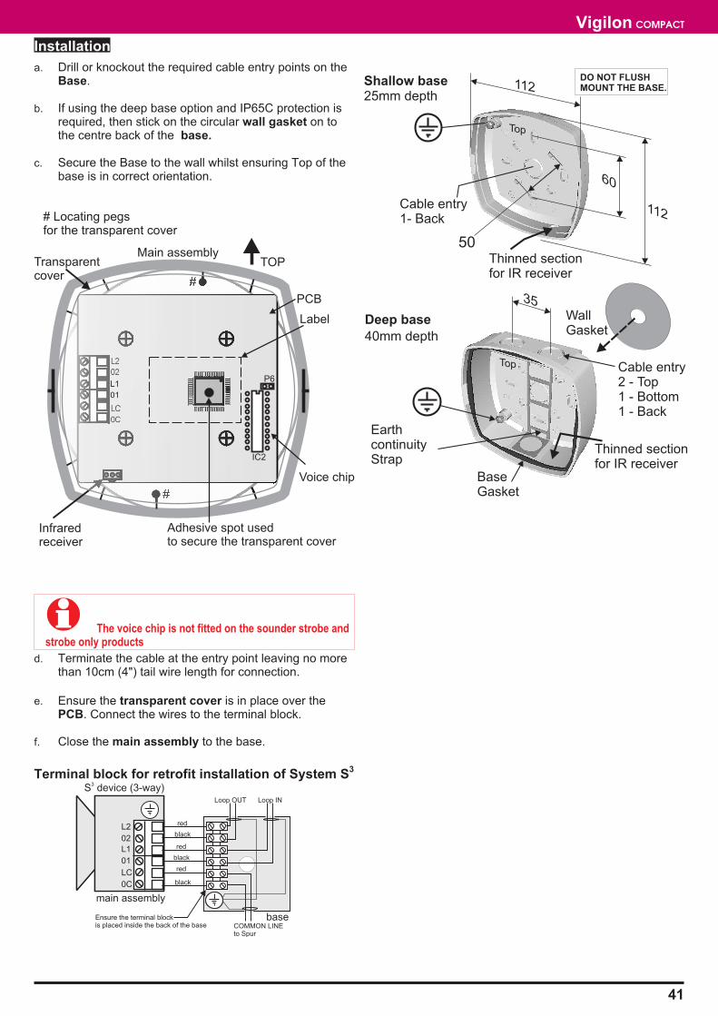
Installation
a. Drill or knockout the required cable entry points on theBase.
b. If using the deep base option and IP65C protection isrequired, then stick on the circular wall gasket on tothe centre back of the base.
c. Secure the Base to the wall whilst ensuring Top of thebase is in correct orientation.
� The voice chip is not fitted on the sounder strobe andstrobe only products
d. Terminate the cable at the entry point leaving no morethan 10cm (4") tail wire length for connection.
e. Ensure the transparent cover is in place over thePCB. Connect the wires to the terminal block.
f. Close the main assembly to the base.
Terminal block for retrofit installation of System S3
41
Vigilon COMPACT
112
50
60
35
25mm depth
40mm depth
Shallow base
Deep base
Top
Top
Cable entry1- Back
112
BaseGasket
Thinned sectionfor IR receiver
Thinned sectionfor IR receiver
EarthcontinuityStrap
Cable entry2 - Top1 - Bottom1 - Back
WallGasket
DO NOT FLUSHMOUNT THE BASE.
LC
0C
L1
01
L2
02
LC
0C
L1
01
main assembly
L2
02
base
S device (3-way)3
red
black
red
black
red
black
Loop INLoop OUT
COMMON LINEto Spur
Ensure the terminal blockis placed inside the back of the base
TOP
02
L2
0C
LC
Infraredreceiver
Main assembly
# Locating pegsfor the transparent cover
#
#
PCB
Label
Transparentcover
IC2
P6
Voice chip
01
L1
Adhesive spot usedto secure the transparent cover
Sounder standard type
Technical specification
Sound output BS5839: Part 1Sound output typically 98 dBA at 1 metre
DimensionsStandard variant
environmentally protected
height 108 mmwidth 108 mmdepth 112 mm
height 180 mmwidth 180 mmdepth 155 mm
Full assembly weight 1.1Kg -approximate for standard variant4Kg - environmentally protected
Storage temperature -30 to 70ºC
Operating temperature 0 to 50°C
Relative Humidity(Non condensing)Temperature 5 - 45°C
up to 90%
Emission BS EN50081-1:1992 Part 1 Residential,Commercial & Light Industry Class B limits
Immunity BS EN50130-4: 1996: Part 4Alarm systems: ElectromagneticcompatibilityProduct family standard: Immunityrequirements for components of fire, intruderand social alarm systems
Ingress Protection IP30 - estimated standard typeIP66 - Environmentally protected type
Vibration 5 to 60Hz
Colour White
Operating voltage 20-50V
Loop Maximum number per loop = 40Load factor = 25
(load factor 1000 max per loop)
2/3-way device (terminals provided for spurcircuit
Installation
a. Check the contents of the package.
Component QuantityHorn Assembly 1Back Box 1Earth Link 1 (for 2 Way) 2 (for 3 Way)Self Tapping Screw 2Allen Key 1
b. Use the key supplied to unlock and hinge open thehorn assembly from the back box.
c. Cut the required cable entry holes using the recessedcentres on the back box.
d. Feed the cables through the entry holes and mount theback box to an even surface or BESA box.
� The loop cable screen must be electrically connectedto the metalised coating in the backbox, either directly via fixingscrews or using the earth point, in order to maintain earthcontinuity.
e. Terminate the cables at the entry to the back boxutilising the earth links to provide earth continuity fortwo cable termination. As an alternative the earthpoint in the back box can be used.
f. Hook the horn assembly onto the back box andsecure the terminal block to the fixing pillars in theback box using the self tapping screws.
g. Connect the cable ends to the terminal block.h. Close the horn assembly onto the back box and
secure it using the allen key.
42
Installation instructions
main assembly
baseAlarm sounder3-way
red
black
red
black
red
black
Loop IN
Loop OUT
COMMON LINEto Spur
Ensure the terminal blockis placed inside the back of the base
5 RECESSED CENTRES
FOR CABLE ENTRY
(MAX OF 3 CAN BE USED)
TERMINAL BLOCK ON
FLYING LEADS
DRILL OUTS
SPACE FOR REAR
CABLE ENTRY
BASE ASSEMBLY
FIXING PILLARS (2 OFF)
FOR THE TERMINAL BLOCK
EARTH POINTHORN ASSEMBLY
Fixing Screw
FLYING LEAD
METALISED COATING
TO FACILITATE EARTH
CONTINUITY TO
LOOP CABLE SCREEN
L1
01
L2
02
LC
0C
L1 01L2 02LC 0C L1 01L2 02
2-wayAlarm sounderterminals
Environmentally protectedsounder
Standard sounder
Environmentally protectedproductsThese units have IP66 rating as specified in the British StandardBS 5490:1977 which is the specification for classification of degree ofprotection provided by enclosures.
EP products: Heat Sensor, Manual Call Point and 3-way Sounder
a. Remove the front cover of the unit disconnecting anyflying leads attached to the terminal block.
b. Place the unit in the desired position and mark the fourfixing holes. When the product is mounted ensure thepre-machined cable entries are at the bottom.
c. Drill the four fixing holes and mount the unit.
� When using PYROTENAX cable, the cables MUST beterminated using PYROTENAX glands (Code No. RGM 2L1.5),screw-on seals (Code No. RPS 2L1.5) or equivalent and astandard M20 locknut.
d. Feed the cables into the unit. Ensure that the sealingwasher supplied is fitted between the cable gland andthe unit (rubber part of the washer against the unit).Use the earth continuity straps provided to maintainloop cable earth continuity.
e. Connect the earth tails into the earth termination point.f. Terminate the cable at the entry point and connect
ends into the appropriate terminals on the sealedprinted circuit board module. See the relevantconnection diagram.
� Failure to promptly replace the cover will resultin environmental damage.
g. Reconnect the flying leads from the cover into theappropriate terminals on the sealed printed circuitboard module. Refit the cover to the unit. Formaximum protection ensure that the cover screws aretight and secure.
� Forcing the cover to fit the wrong way round willdamage the unit.
Heat Probe
For carriage purposes the probe on the heat sensor is fully retracted. Itis important that the heat probe is positioned correctly. There should bea minimum of 20mm of the probe protruding from the front face of theprobe gland. The probe gland can only be tightened up once, as thegland uses an olive joint which should be replaced rather thanre-tightened. Once the probe is in the correct position and the gland hasbeen tightened (finger tight plus 11/2 turns) the cable tie should be usedto clamp the cable to the front cover
43
Vigilon COMPACT
Heatsensor
TH-
TH+
LED
-
LED
+
0V
LIN
E2
0v
LIN
E1
AN
Y
AN
Y
WH
ITE
RED
0V
LIN
E1
0V
LIN
E2
THERM
ISTO
R
PRO
BE
(ON
CO
VER)
LED
(ON
CO
VER)
LOO
PO
UT
TON
EX
T
DEVIC
E
LOO
PIN
FRO
MPREVIO
US
DEVIC
E
ManualC
all
Poin
t
CA
LL2
CA
LL1
LED
-
LED
+
0V
LIN
E2
0v
LIN
E1
BRO
WN
BLU
E
WH
ITE
RED
0V
LIN
E1
0V
LIN
E2
CA
LLPO
INT
CO
NTA
CTS
(ON
CO
VER)
LED
(ON
CO
VER)
LOO
PO
UT
TON
EX
T
DEVIC
E
LOO
PIN
FRO
MPREVIO
US
DEVIC
E
Ala
rmS
ounder
(3-W
ay)
S2 S1 0V
LIN
E3
0V
LIN
E2
0v
LIN
E1
GREY
RED
0V
LIN
E3
0V
LIN
E1
0V
LIN
E2
SOU
ND
ER
(ON
CO
VER)
SPU
R
LOO
PO
UT
TON
EX
T
DEVIC
E
LOO
PIN
FRO
MPREVIO
US
DEVIC
E
Centre mark
Cable entry points
167mm
16
5m
m
Earth terminals
EP product with cover removed
Manual call points
Options
The surface mountable Manual Call Point range includes:
� MCP - LPC certified
� MCP water resistant IP44
� MCP environmentally protected IP55
� MCP with lift-up cover
� MCP with lift-up cover, water resistant IP44
� Surface mounted MCP with key switch
� If the MCP is flush mounted the plastic backboxsupplied must be used. A flush fixing bezel is available.
Technical specification
Standard BS5839: Part 2 (break glass type only)
DimensionsStandard variant
Environmentally protected
height 88 mm x width 88 mmdepth 70 mm
height 180 mm x width 180 mm xdepth 130 mm
Full assembly weight 770g - approximate for standard MCP3.5Kg - environmentally protected MCP
Storage temperature -30 to 70ºC
Operating temperature 0 to 50°C
Relative Humidity(Non condensing)Temperature 5 - 45°C
up to 90%
Emission BS EN50081-1:1992 Part 1 Residential,Commercial & Light Industry Class B limits
Immunity BS EN50130-4: 1996: Part 4Alarm systems: ElectromagneticcompatibilityProduct family standard: Immunityrequirements for components of fire, intruderand social alarm systems
Ingress Protection IP40 estimated standard type
IP44 estimated water resistant typeIP66 estimated environmentally protectedtype
Colour Red
Case ABS engineering plastic
Indication Red LED that illuminates when the MCP isoperated
Testing The mechanism and operation of the MCP istested by using a test key
Operating voltage 20-50V
Loop Maximum number per loop = 200Load factor = 1(load factor 1000 max per loop)
2-way device
44
Installation instructions
Environmentallyprotected MCP
Keyswitch MCP
FIREBREAK GLASS
FIRE
FIREPRESS HARD TO
BREAK GLASS
88mm
88mm
surface flush
33mm70mm
Installation
See also section on the environmentally protected range.
Surface Fixing
a. Check the contents of the manual call point package:
Component QuantityCall point Assembly 1Back Box 1Earth Link 1Test Key 1Long Screw 2Small Screw 1Gasket 1 (Only supplied
with weather resistant versions)b. Cut the required holes on the back box for cable entry
and also on the square gasket if applicable.c. Feed the cables through the entry holes and mount the
back box with the Square Gasket, if used, to an evenwall surface using suitable fixing.
d. Terminate each cable entry at the back box utilising theearth link to maintain cable earth continuity.
e. Disassemble the call point assembly using the end ofthe test key to open the socket head screw.
f. Feed the cable tails through the spacer/back boxgasket, if used and connect the cable ends to the loopterminals provided in the spacer assembly.
� Ensure the spacer/back box gasket is fitted on andaround the back box profile.
g. Secure the spacer assembly to the back box using the2 - long screws.
h. Re-assemble the cover assembly to the mainassembly with the socket head screw. To do this:
i) Fit the spacer/cover gasket, if used.
ii) Insert the glass in a sloping position.
iii) Hang the test key in its operating position.
iv) Place the cover/glass gasket, if used, over the glasswith its bevelled edge outwards.
v) Hook the cover onto the main assembly securing thetwo parts with the allen screw, and remove thetest key to leave the call point in its normaloperating state.
� Check the cover/glass gasket is not trapped aroundthe circular rim of the cover.
vi) Fit the socket head screw to secure the cover ontothe main assembly. A weather resistant version issupplied with a longer socket head screw.
� Semi-Flush Fixing: When flush fixing the call point,the red plastic back box supplied must be flushed into the wall.The procedure for installation is similar to the surface fixingversion except a MCP SEMI FLUSH KIT containing a flush plateis required and must be installed between the back box andspacer assembly.
The water resistant call points cannot be flush fixed.
Test
Push the test key through the hole on the underside of the call point toengage the test cam mechanism. Push to operate the cam mechanism.At this point the test key is retained in the call point. Pulling the test keyout will reset the glass.
45
Vigilon COMPACT
RECESSED CENTRES
FOR CABLE ENTRIES
3-TOP & 1-BOTTOM
(MAX OF 2 USABLE) SPACE FOR
BACK CABLE
ENTRY
FIXING SCREWS
2-OFF FOR PCB
ASSY MOULDING
EARTH POINT
THIS WAY UP
1.4m
FLOOR LEVEL
4-OFF DRILL OUTS FOR
CONDUIT BOX MOUNTING
NOTE : ITEMS MARKED * ARE SUPPLIED
WITH WATER RESISTANT VERSION ONLY
BACKBOX
36mm DEPTH
LOOP TERMINATIONS
LINE2
LOOP
OUT
L2 OV
LINE1
LOOP
IN
L1 OV
SQUARE GASKET
BLACK BOX
SPACER/BACK BOX GASKET
SPACER/COVER GASKET
LONG SCREWS
GLASS
COVER/GLASS GASKET
COVER
SOCKET HEAD SCREW
SPACER ASSEMBLY
10 9 8 7 6 5 4 3 2 1
1
2
3
4
5
6
7
8
9
10
88mm
88
mm
Depth: 70mmwithout Gaskets
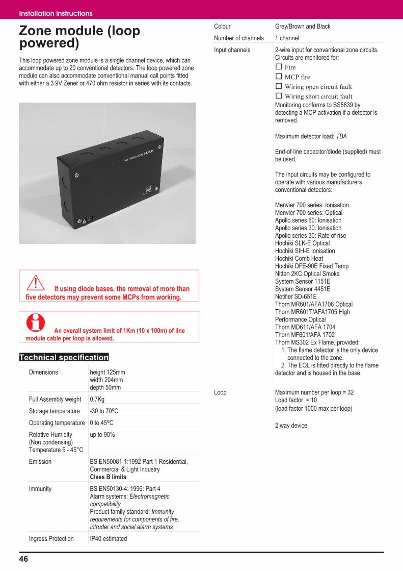
Zone module (looppowered)This loop powered zone module is a single channel device, which canaccommodate up to 20 conventional detectors. The loop powered zonemodule can also accommodate conventional manual call points fittedwith either a 3.9V Zener or 470 ohm resistor in series with its contacts.
� If using diode bases, the removal of more thanfive detectors may prevent some MCPs from working.
� An overall system limit of 1Km (10 x 100m) of linemodule cable per loop is allowed.
Technical specification
Dimensions height 125mmwidth 204mmdepth 50mm
Full Assembly weight 0.7Kg
Storage temperature -30 to 70ºC
Operating temperature 0 to 45ºC
Relative Humidity(Non condensing)Temperature 5 - 45°C
up to 90%
Emission BS EN50081-1:1992 Part 1 Residential,Commercial & Light IndustryClass B limits
Immunity BS EN50130-4: 1996: Part 4Alarm systems: ElectromagneticcompatibilityProduct family standard: Immunityrequirements for components of fire,intruder and social alarm systems
Ingress Protection IP40 estimated
Colour Grey/Brown and Black
Number of channels 1 channel
Input channels 2-wire input for conventional zone circuits.Circuits are monitored for:
� Fire
� MCP fire
� Wiring open circuit fault
� Wiring short circuit fault
Monitoring conforms to BS5839 bydetecting a MCP activation if a detector isremoved.
Maximum detector load: TBA
End-of-line capacitor/diode (supplied) mustbe used.
The input circuits may be configured tooperate with various manufacturersconventional detectors:
Menvier 700 series: IonisationMenvier 700 series: OpticalApollo series 60: IonisationApollo series 30: IonisationApollo series 30: Rate of riseHochiki SLK-E OpticalHochiki SIH-E IonisationHochiki Comb HeatHochiki DFE-90E Fixed TempNittan 2KC Optical SmokeSystem Sensor 1151ESystem Sensor 4451ENotifier SD-651EThorn MR601/AFA1706 OpticalThorn MR601T/AFA1705 HighPerformance OpticalThorn MD611/AFA 1704Thorn MF601/AFA 1702Thorn MS302 Ex Flame, provided;
1. The flame detector is the only deviceconnected to the zone.
2. The EOL is fitted directly to the flamedetector and is housed in the base.
Loop Maximum number per loop = 32Load factor = 10
(load factor 1000 max per loop)
2 way device
46
Installation instructions
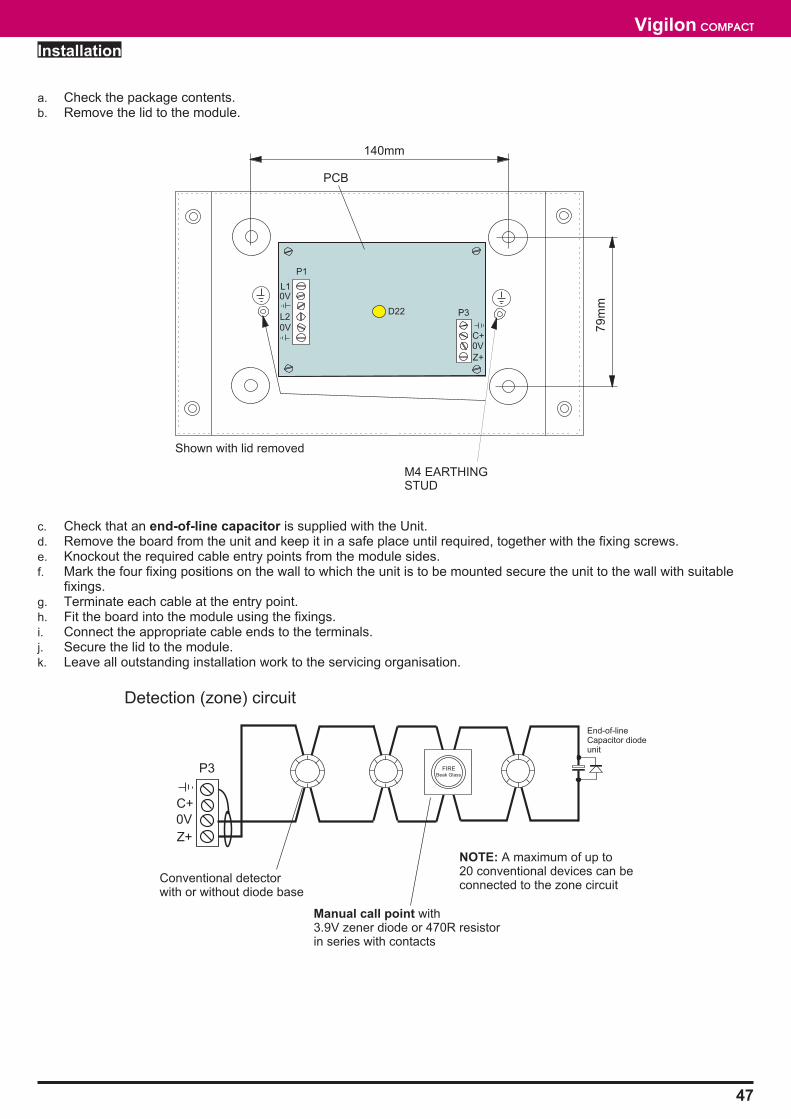
Installation
a. Check the package contents.b. Remove the lid to the module.
c. Check that an end-of-line capacitor is supplied with the Unit.d. Remove the board from the unit and keep it in a safe place until required, together with the fixing screws.e. Knockout the required cable entry points from the module sides.f. Mark the four fixing positions on the wall to which the unit is to be mounted secure the unit to the wall with suitable
fixings.g. Terminate each cable at the entry point.h. Fit the board into the module using the fixings.i. Connect the appropriate cable ends to the terminals.j. Secure the lid to the module.k. Leave all outstanding installation work to the servicing organisation.
47
Vigilon COMPACT
FIREBeak Glass
Detection (zone) circuit
Conventional detectorwith or without diode base
Manual call point with3.9V zener diode or 470R resistorin series with contacts
NOTE: A maximum of up to20 conventional devices can beconnected to the zone circuit
P3
C+
0V
Z+
End-of-lineCapacitor diodeunit
P1
D22 P3
PCB
M4 EARTHINGSTUD
Shown with lid removed
140mm
79m
m
L10V
L20V
C+0V
Z+

Single channel interface(loop powered)
This Single channel interface unit operates directly from the loop. It has1 channel that can be configured as either an input or an output.
When the unit is set up as an output, the input channel can still be usedas a verification input of the output action.
When the unit is configured as a single input, a line module must beinstalled and can be up to 100m cable distance away. The two positionswitch on the unit must be set to input.
When the unit is configured for multiple input, an end of line capacitorunit must be fitted to the last input. If the multiple inputs are from manualcall points, there must be a 470 ohm resistor in series with the contacts.
As a relay output the unit provides voltage free change over contactsrated 5A at 24Vdc. The relay output of the interface operates with asystem sector.
� The cable length usage per loop to include lengths ofcables on each interface input / output lines must not exceed1Km.
Technical specification
Dimensions height 125mmwidth 204mmdepth 50mm
Full Assembly weight 0.702Kg
Storage temperature -30 to 70ºC
Operating temperature 0 to 45ºC
Relative Humidity(Non condensing)Temperature 5 - 45°C
up to 90%
Emission BS EN50081-1:1992 Part 1 Residential,Commercial & Light IndustryClass B limits
Immunity BS EN50130-4: 1996: Part 4Alarm systems: Electromagnetic compatibilityProduct family standard: Immunityrequirements for components of fire, intruderand social alarm systems
Ingress Protection IP40 estimated
Colour Grey/Brown and Black
Number of channels 1 channel, (configurable as input or output)
Input channels Single input (using optional line module):monitors voltage free contacts,normally open or normally closed,inputs may be configured as:
fire,fault,supervisory
(with 0s or 30s delay before signal accepted)
Multiple input (with capacitor end of line unit):monitors voltage free contacts(in series with 470 ohm resistor for MCPs)normally open or normally closed,inputs may be configured as:
fire only(with 0s or 30s delay before signal accepted)
Output channels Voltage free SPCO contacts rated at:5 amps at 24 Vdc
Loop Maximum number per loop = 32Load factor = 10
(load factor 1000 max per loop)
2-way device
48
Installation instructions
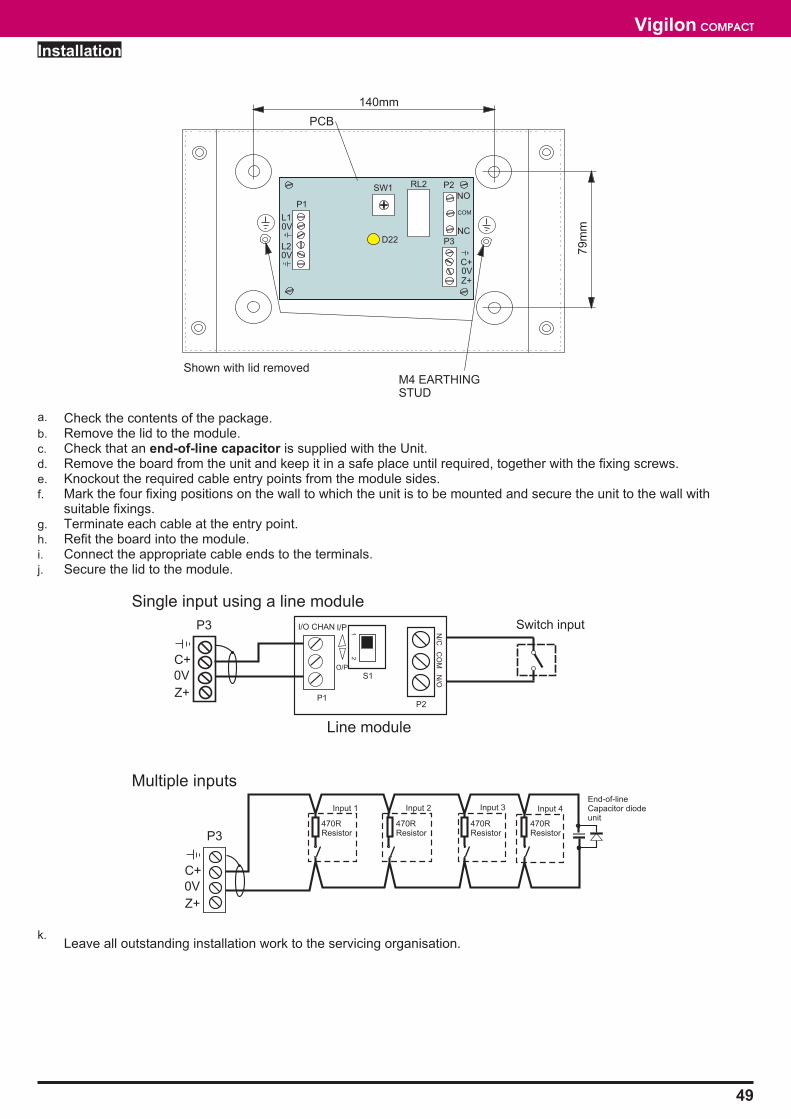
Installation
a. Check the contents of the package.b. Remove the lid to the module.c. Check that an end-of-line capacitor is supplied with the Unit.d. Remove the board from the unit and keep it in a safe place until required, together with the fixing screws.e. Knockout the required cable entry points from the module sides.f. Mark the four fixing positions on the wall to which the unit is to be mounted and secure the unit to the wall with
suitable fixings.g. Terminate each cable at the entry point.h. Refit the board into the module.i. Connect the appropriate cable ends to the terminals.j. Secure the lid to the module.
k.Leave all outstanding installation work to the servicing organisation.
49
Vigilon COMPACT
Line module
Single input using a line module
Multiple inputs
Switch inputP3
C+
0V
Z+
P3
C+
0V
Z+
N/C
CO
MN
/O
P2
12
S1
I/P
O/P
I/O CHAN
P1
470RResistor
Input 1 Input 2 Input 3 Input 4End-of-lineCapacitor diodeunit
470RResistor
470RResistor
470RResistor
P1
D22 P3
P2RL2SW1
Shown with lid removed
PCB
M4 EARTHINGSTUD
140mm
79m
m
L10V
L20V
0VC+
Z+
NC
COM
NO
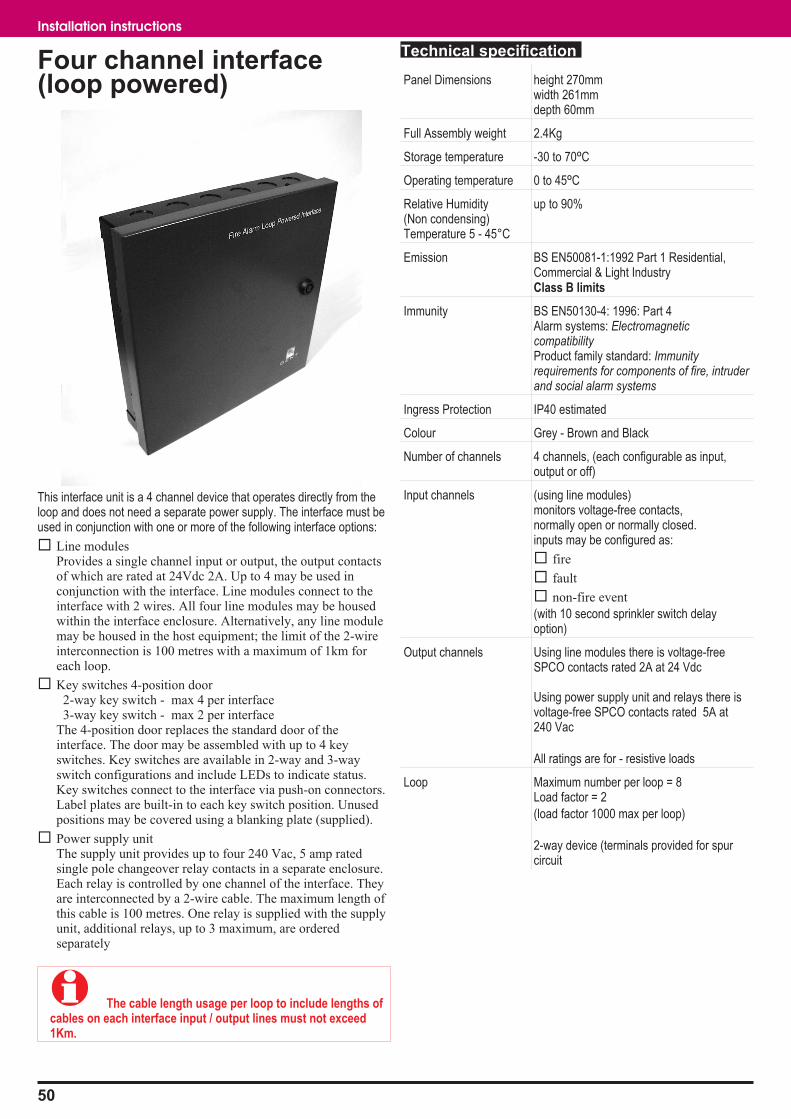
Four channel interface(loop powered)
This interface unit is a 4 channel device that operates directly from theloop and does not need a separate power supply. The interface must beused in conjunction with one or more of the following interface options:
� Line modulesProvides a single channel input or output, the output contactsof which are rated at 24Vdc 2A. Up to 4 may be used inconjunction with the interface. Line modules connect to theinterface with 2 wires. All four line modules may be housedwithin the interface enclosure. Alternatively, any line modulemay be housed in the host equipment; the limit of the 2-wireinterconnection is 100 metres with a maximum of 1km foreach loop.
� Key switches 4-position door2-way key switch - max 4 per interface3-way key switch - max 2 per interface
The 4-position door replaces the standard door of theinterface. The door may be assembled with up to 4 keyswitches. Key switches are available in 2-way and 3-wayswitch configurations and include LEDs to indicate status.Key switches connect to the interface via push-on connectors.Label plates are built-in to each key switch position. Unusedpositions may be covered using a blanking plate (supplied).
� Power supply unitThe supply unit provides up to four 240 Vac, 5 amp ratedsingle pole changeover relay contacts in a separate enclosure.Each relay is controlled by one channel of the interface. Theyare interconnected by a 2-wire cable. The maximum length ofthis cable is 100 metres. One relay is supplied with the supplyunit, additional relays, up to 3 maximum, are orderedseparately
� The cable length usage per loop to include lengths ofcables on each interface input / output lines must not exceed1Km.
Technical specification
Panel Dimensions height 270mmwidth 261mmdepth 60mm
Full Assembly weight 2.4Kg
Storage temperature -30 to 70ºC
Operating temperature 0 to 45ºC
Relative Humidity(Non condensing)Temperature 5 - 45°C
up to 90%
Emission BS EN50081-1:1992 Part 1 Residential,Commercial & Light IndustryClass B limits
Immunity BS EN50130-4: 1996: Part 4Alarm systems: ElectromagneticcompatibilityProduct family standard: Immunityrequirements for components of fire, intruderand social alarm systems
Ingress Protection IP40 estimated
Colour Grey - Brown and Black
Number of channels 4 channels, (each configurable as input,output or off)
Input channels (using line modules)monitors voltage-free contacts,normally open or normally closed.inputs may be configured as:
� fire
� fault
� non-fire event
(with 10 second sprinkler switch delayoption)
Output channels Using line modules there is voltage-freeSPCO contacts rated 2A at 24 Vdc
Using power supply unit and relays there isvoltage-free SPCO contacts rated 5A at240 Vac
All ratings are for - resistive loads
Loop Maximum number per loop = 8Load factor = 2
(load factor 1000 max per loop)
2-way device (terminals provided for spurcircuit
50
Installation instructions
Installation
Fuse RatingFS1 to FS4 100mA 20mm x 5mm
a. Check the contents of the packagesOpen the door using the key.
Component QuantityUnit 1Interface board# 1Screws (for board)# 5Key 1
#these components are packaged separatelyb. Knockout the required cable entry points.
� Only mount the unit with cable entry points at the top.
c. Mark and drill the three hole fixing positions on thesurface to which the unit is to be mounted and securethe unit to the surface with suitable fixings.
d. Terminate each cable at the entry point.e. Fit the interface board using the screws provided.f. Fit the line modules inside the backbox, if required.g. Connect the appropriate cables ends to their respective
terminals.
� The connection of internally fitted line module shouldbe left for the Servicing organisation, unless otherwiseinstructed.
A remotely installed line module should not be located morethan 100m cable distance away from the interface unit, assuming1.5mm2 MICC is being used. An overall limit of 1Km (10 x 100m)
of line module monitoring cable is allowed per loop.
h. Close the door on the unit using the key.i. Leave all outstanding installation work to the servicing
organisation.
Keyswitch door
� Where interface unit inputs are keyswitch operated,there is an optional replacement door. The door canaccommodate keyswitches 19245-03 (2 off 3-way keyswitch) or19245-02 (4 off 2-way keyswitch).
.
� If a keyswitch is fitted to a channel, no line modulecan be connected to that channel.
51
Vigilon COMPACT
P5 P6 P7 P8 P10 P11
P2
P1
P2
P1
P2
P1
P2
P1
EARTH LEAD
CABLE ENTRIES
6-BACK
6-TOP
INTERFACEUNIT
UP TO 4-OFF
OPTIONALLINEMODULES
BOARD
DOOR
85mm
3-off BACK and1-off TOPEARTH POINTSfor CABLES
CABLE ENTRIESFOR LOOP
WIRING
149m
mP1CH1
P2
CH2
P3
CH3
P4
CH4
FS1 FS2 FS3 FS4
85mm
P 5 P 6 P 7 P 8 P 1 0 P 11
P2
P1
N/C COM N/O
N/C COM N/ON/C COM N/ON/C COM N/O
I/O CHAIN
I/O CHAINI/O CHAINI/O CHAIN
CH4CH3CH2CH1
INTERFACE UNIT(LOOP POWERED)
L1 0V L2 0V
P2
P1
P2
P1
P2
P1
OUTPUT
INPUTUp to 100mcable distance
Line modules can be fitted insidethe interface unit or externally.
LINEMODULE
EXTERNALEQUIPMENT
1
2
3
4
P1 to P4
CONFIRMATIONLED
KEYSWITCH
KEYSWITCH DOORfor interface unit
2-WAY KEYSWITCH
3-WAY KEYSWITCH
To -> P1, P2, P3 or P4
To -> P1 & P2or
P3 & P4
INTERFACE BOARDKEYSWITCH ASSEMBLY
LABEL
DRESS NUT
LOCK NUT
DOOR (PART OF)
LABEL HOLDER
P1
CH1
P2
CH2
P3
CH3
P4
CH4

Power supply unit (for 4channel loop poweredinterface)The power supply unit allows connection to externalequipment that requires switched mains voltages viachange over contacts. The change over contacts areavailable at terminals P1 to P8.
Panel Dimensions height 208mmwidth 222mmdepth 60mm
Full assembly weight 1.5Kg
Storage temperature -30 to 70ºC
Operating temperature 0 to 45ºC
Relative Humidity(Non condensing)Temperature 5 - 45°C
up to 90%
Emission BS EN50081-1:1992 Part 1 Residential,Commercial & Light IndustryClass B limits
Immunity BS EN50130-4: 1996: Part 4Alarm systems: ElectromagneticcompatibilityProduct family standard: Immunityrequirements for components of fire, intruderand social alarm systems
Ingress Protection IP40 estimated
Colour Grey - Brown and Black
Outputs 4 pairs of change over contacts rated 5A at240Vac resistive load.
The change over of contacts occur onoperation of the respective interface outputchannel.
Power indicator Green power on indicator is lit when power ishealthy
Installation
Fuse Rating LocationMains 1A HRC 20mm x 5mm Mains terminal block
a. Check the contents of the package.b. Using the key open the door.c. Knockout the required cable entry points (6-off on top
of case).
� The unit must be mounted with the cable entry pointsat the top of the unit.
d. Mark and drill the four fixing hole positions on thesurface to which the unit is to be mounted and securethe unit to the surface with suitable fixings.
e. Terminate cables at the entry points and connect thecables ends if instructed, otherwise leave tail wirelength of 400mm and mark the cores to identify theconnection point.
f. Close the door on the unit using the key.
� The unit is supplied complete with 1 PSU RELAY. Theunit is designed to operate a maximum of 4 relays. IndividualPSU RELAYs may be ordered using part code 19245-07.
g. Leave all outstanding installation work for the servicingorganisation.
52
Installation instructions
P16
P12
P14
P15I/
O_
CH
4I/
O_
CH
3I/
O_
CH
2I/
O_
CH
1
CH4CH3CH2CH1
P5 P6 P7 P8
INTERFACE UNIT
POWER SUPPLY UNIT
100m maximum distance
RL4P1&P2
RL3P3&P4
RL2P5&P6
RL1P7&P8
POWER SUPPLYUNIT
200mm
136m
m
6-OFFTOPCABLEENTRYPOINTS
DOOR
P1 P2 P3 P4 P5 P6 P7 P8 P9
P11
P12
P14
P15
P16
P18
P18
P10
RL4 RL3 RL2 RL1
P13
D10
N L
1A
Earth lead
MAINSCABLEENTRYPOINT
N/O COM N/C
P1 to P8

Mains powered interfaceunitThis interface unit operates from mains power and incorporates its ownbattery-backed power supply. It has 4 channels, each may be configuredas input or output and are configured as conventional zone and sectorcircuits respectively.
Technical specification
Dimensions height 305mmwidth 504mmdepth 98mm
Full assembly weight 8.6Kg
Storage temperature -30 to 70ºC
Operating temperature 0 to 45ºC
Relative Humidity(Non condensing)Temperature 5 - 45°C
up to 90%
Mains Operating voltage 230V 50Hz +10% -6%
Input (zone) channels 2-wire inputs for conventional zone circuits.Circuits are monitored for:
� Detector fire
� MCP fire
� Wiring open circuit fault
� Wiring short circuit fault
Monitoring conforms to BS5839 by detectinga MCP activation if a detector is removed.Maximum detector load: 2 mA.
End-of-line capacitor/diode (supplied) must beused.
The input circuits may be configured tooperate with various manufacturers detectorsand MCPs: Gent, Apollo / Hochiki, Menvier,Nittan, Notifier and Thorn
On certain sites where older type detectorsand MCPs are used that give a short circuitfire, set rotary switch to position ‘F’.
Emission BS EN50081-1:1992 Part 1 Residential,Commercial & Light IndustryClass B limits
Immunity BS EN50130-4: 1996: Part 4Alarm systems: Electromagnetic compatibilityProduct family standard: Immunityrequirements for components of fire, intruderand social alarm systems
Ingress Protection IP40estimated
Colour Grey/Brown and Black
Number of channels 4 channels, (each configurable as input oroutput)
Output (sector)channels
Output (sector) channel will operateconventional equipment such as soundersand door holders.
A maximum current of 500mA is allowed andcan be shared between the output channels(each fused at 800 mA).Maximum output current per interface is500mA
Sectors are monitored for:
� wiring open circuit fault
� wiring closed circuit fault
End-of-line 2k2 resistor (supplied) must beused.
Optional up to 4 Octal relays with diode packsmay be fitted within the enclosure. Theseprovide DPCO voltage-free contacts rated at10 amps, 240 Vac, resistive load.
Batteries 2 - 12V 2.1Ah sealed lead acid batteries
Loop Maximum number per loop = 8Load factor = 3(load factor 1000 max per loop)
3-way device (terminals provided for spurcircuit)
53
Vigilon COMPACT
Installation
Fuse Rating Location
Mains 1.6A HRC - 20mm x 5mm Top left of the backboxFS1 800mA - 20mm x 5mm BoardFS2 800mA - 20mm x 5mm BoardFS3 800mA - 20mm x 5mm BoardFS4 800mA - 20mm x 5mm BoardFS5 2.5A - 20mm x 5mm BoardFS6 0.25A - 20mm x 5mm Boarda. Check the package contents, open the door using the
key and check all components.
Component QuantityUnit 1Interface Board# 1Screws (for board)# 712V 2.1Ah Battery 2Key 1Battery Link 1Battery lead 10.25A Aux Fuse (Spare) 11.6A Mains Fuse (Spare) 12.5A Battery Fuse (Spare) 1800mA Quick Blow Fuse (Spare) 4Capacitor Unit (EOL) 4EOL Label 522k Resistor (EOL) 4
# these components are packaged separately.b. If necessary, remove the door on the unit to ease
installation and remove the covers fitted over themains terminal.
c. Knockout the required cable entry points from the backbox.
d. Mark the 3 fixing positions on the wall to which the unitis to be mounted and secure the unit to the wall withsuitable fixings.
� If the unit is to switch heavy non-mains loads, thenoptional POWER RELAYS 19104-52 must be used. The relaysmay be installed on the DIN rail inside the unit. The relay unitmust include a serial diode.
e. Terminate each cable at the entry point.f. Fit the interface board inside the backbox using the
screws provided.g. Connect the incoming cable ends to the appropriate
terminals.h. Connect the transformer secondary wires to terminal
block P7 on the interface board.i. Place the batteries inside the backbox, however do not
make the connection, this is done duringcommissioning by the Servicing organisation.
j. Fit the cover over the mains terminal and batteryrestraint bracket.
k. If removed, re-fit the door and earth lead.
� The capacitor unit and the 22k Resistor must be fittedto the end-of-line (EOL) of each circuit. Also stick an EOL labelinside the last device on each circuit or where the EOL unit isfitted.
l. Close the door on the Unit using the Key.m. Leave all outstanding parts and installation work to the
Servicing organisation.
54
Installation instructions
DIN RAIL FOR
OPTIONALOCTAL TYPE
RELAYS
CABLEENTRYPOINTS
16 - TOP
183mm
BACK BOX
NOTE: The batteryrestraint bracketsare not shown.
BOARD
P3 P4 P5 P6 P2
AC AC
P7Aux
P9Battery
P8+ - + -
CABLEENTRIESFORLOOPWIRING
1.6AMAINSFUSE
N E L
CABLEENTRIES
FOR
MAINSWIRING
218mm 218mm
EARTHLINK TODOOR
DOOR BATTERY
RESTRAINT
FIXING
POINT
2-OFF 12VBATTERIES
2.1Ah
40mm
FS1 FS2 FS3 FS4
FS5
FS6
S5
External circuits Power relay
Up to 4 relays can be fitted inside the interface unit on the DIN rail.
� Octal relay operates from a 24V supply
� DIN rail mountable
� Relay coil resistance 470R
� Contacts rated 10A at 230Vac
55
Vigilon COMPACT
S1
-
S1
+
EA
RT
H Z1
ZC
1
End-of-line22K Resistor
P3 to P6
OUTPUT USED
S1
-
S1
+
EA
RT
H Z1
ZC
1
End-of-lineCapacitor unit
P3 to P6
INPUT NOT USED
S1
-
S1
+
EA
RT
H Z1
ZC
1
P3 to P6
End-of-line22K Resistor
Conventionaldetector or MCP
S1
-
S1
+
EA
RT
H Z1
ZC
1
P3 to P6
End-of-lineCapacitor unit
INPUT USED
P2
0V LC 0V L1 0V L2
COMMON
LINE
LOOP IN
LINE 1
LOOP OUT
LINE 2
LOOP WIRING
SPUR CIRCUIT
(WHERE USED)
LOOP CIRCUIT
OUTPUT NOT USED
DIODE UNIT
(TS35 DIN RAIL MOUNTABLE)
2S 3S
1S 4S
14 N/O 112 N/C 124 N/O 2
22 N/C 2
21 COM 2
COIL
A2
-ve
+ve
3S
1S4S
2S
DiodeUnit
A1
11 COM 1
2
7
3 4
1
6 5
8
6 5 4 3
24 22 12 14
A2 21 11 A1
7 8 1 2
HOLDERTOP VIEW
(TS35 DIN RAIL MOUNTABLE)

Vigilon compact system partsThis section lists parts that can be used in Vigilon compact system. For further details on the availability of the parts, contact your supplier.
Control Panels
The panel are supplied as first and second fix assemblies in separate package.
Compact-24 Control panel (EN54) c/w 1 - Loop card with 2-12V 12Ah batteries for 24hr standby
Accessories
COMPACT-FLUSH Compact-24 flush frame
COMPACT-FLUSH-SS Compact flush frame stainless steel (Compact-24)
COM-INN-DR24 Compact-24 inner door assembly
COM-OUT-DR24 Compact-24 outer door assembly
4015-514 1 - 12V 12Ahr Battery pack
VIG-WR-CASE Control panel weather resistant case
COMPACT-LPC Loop Card (EN54)
2434T670 Master Control board Compact-24
2434T672 DKC
2434T675 PSU Compact-24
Repeat panels
COMPACT-RPT Repeat indicator panel (connects directly to the control panel)
NOTE: These are loop connectable panels and are supplied as first and second fix assemblies in separate package.
VIG-RPT-1ST-FIX Repeat panel backbox
VIG-RPT Repeat panel (EN54)
VIG-BATT-RPT Battery pack for repeat/mimic panel
Mimic panels
VIG-MIM A2 Mimic panel c/w drawing (EN54)
VIG-ZONE A2 Zonal mimic panel (EN54)
VIG-MIM-A4 A4 Mimic Panel (EN54)
VIG-ZONE-A4 A4 Zonal Mimic Panel (EN54)
VIG-BATT-RPT Battery pack for repeat/mimic panel
56
Installation instructions

Sensors
COMPACT-O Optical sensor
34710 Optical heat sensor
19271-01 Replacement Optical chamber
34710-RL Optical heat sensor for remote LED connection
13449-01 Remote LED
34710-ML Optical heat sensor with MCP connection(Chinese market only)
34770 Optical heat sensor sounder
19271-01 Replacement Optical chamber
34780 Heat sounder
19274-01 Replacement heat sounder chamber
34720 Heat sensor
19272-01 Replacement heat chamber
34729 Environmentally protected Heat sensor
34740 Beam sensor pair
34741-01 Angle bracket with base
34741-90 IP66 Angle bracket with base
34741-03 Parallel bracket with base
4334-035 Light shield for beams
34760 Duct sensor (inc 17908-05 Probes& 34702 Slave LED unit)
Terminal Plate34700 3-way terminal plate
34704 4-way terminal plate
19279-01 Semi-flush sensor mounting kit
19279-10 Sensor trim ring (10 pack)
1270-50 Sensor dust cover (50 pack)
Tools17918-22 Sensor chamber Extractor cup
17918-23 Optical chamber electronics module removal tool
17918-24 Ionisation chamber electronics module removal tool
17918-25 Heat sensor electronics module removal tool
17918-26 Sensor removal tool kit
T Breaker and Slaves
34701 T breaker Unit
34702 Slave LED unit
34703 Slave Relay unit
57
Vigilon COMPACT
Alarm sounders
34203 Sounder T-Breaker
34213 Environmentally protected Sounder T-Breaker
34777 Repeat sounder (34700 Terminal plate required)
S3
Addressable Speech, Sounder Strobe
Strobe
Low profile range
Body Strobe - Deep base
White S2IP-ST-WR (red lens) S2IP-ST-WA (amber lens)
Red S2IP-ST-RR (red lens) S2IP-ST-RW (white lens)
Sounder Strobe
Low profile range
Sounder Sounder Strobe (red lens)
Body Deep base Shallow base Deep base Shallow base
White S3IP-SN-W S3-SN-W S3IP-SN-ST-WR S3-SN-ST-WR
Red S3IP-SN-R S3-SN-R S3IP-SN-ST-RR S3-SN-ST-RR
Low profile variants
Sounder Strobe
The S2IP-SN-R3 and S2IP-SN-W3products are suitable for retrofittingand are supplied with a 6-way terminalblock to ease cable connection.
Red S3IP-SN-ST-RW (white lens)
White S3IP-SN-ST-WA (amber lens)
System range
Sounder
Red S2IP-SN-R (2-way) S2IP-SN-R3 (3-way)
White S2IP-SN-W (2-way) S2IP-SN-W3 (3-way)
Note: The system range of products do not support strobe options.
Speech Sounder Strobe
Low profile range
Speech Sounder Speech Sounder Strobe (red lens)
Deep base Shallow base Deep base Shallow base
White S3IP-VO-W S3-VO-W S3IP-VO-ST-WR S3-VO-ST-WR
Red S3IP-VO-R S3-VO-R S3IP-VO-ST-RR S3-VO-ST-RR
System range
Speech Sounder
Deep base
White S2IP-VO-W
Red S2IP-VO-R
Note: The system range of products do not support strobe options.
Remote Control
S3-CONTROL Remote control for the S3
58
Installation instructions

Manual call points (MCP) 2-way
34800 Surface mounted MCP
34807 Surface mounted keyswitch MCP
34842 Surface mounted MCP with cover
34812 Surface mounted water resistant MCP
19289-01 MCP flush fixing plate
34852 Surface mounted water resistant MCP with cover
34829 Environmentally protected surface mounted MCP
14112-09GR Spare MCP glasses 10 pack non LPCB approved
Interfaces
4- Channel mains powered interface
34440 Mains powered fire alarm interface
19104-52 Power relay (for mains powered interface)(up to 4 maximum can be fitted inside the interface - supplied with base and diode)
4- Channel loop powered interface
34450 4 - Channel loop powered fire alarm interface
19245-05 Interface line module-up to 4 can be fitted in a 4 channel loop powered fire alarm interface
34454 4 way keyswitch door for 4-channel loop powered interface
19245-02 2 position keyswitch assembly (for use with optional interface doors)
19245-03 3-position keyswitch assembly (for use with optional interface doors)
Power supply unit
19245-06 Power supply unit with 1 relay (for use with loop powered interface unit)
19245-07 Mains relay (up to 4 for use with 19245-06 unit)
1- Channel loop powered interface
34410 Loop powered zone module
34415 Single Channel loop powered interface
19245-05 Interface line module
Manuals
4188-750 Vigilon Compact Installation instructions
4188-751 Vigilon Compact Operating instructions
4188-749 Log book
59
Vigilon COMPACT

Notes
60
Installation instructions

Notes
61
Vigilon COMPACT

Notes
62
Installation instructions

Notes
63
Vigilon COMPACT

4188-750_issue 2_03/03