intruder alarm system engineering · pdf fileintruder alarm system engineering information the...
TRANSCRIPT
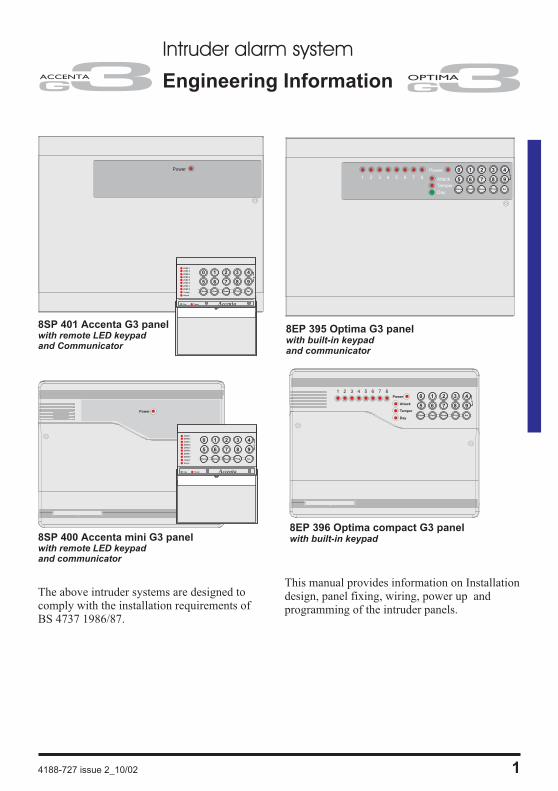
Intruder alarm system
Engineering Information
The above intruder systems are designed tocomply with the installation requirements ofBS 4737 1986/87.
This manual provides information on Installationdesign, panel fixing, wiring, power up andprogramming of the intruder panels.
4188-727 issue 2_10/02 1
Power 0 1 2 3
5 6 7 8
Chime Omit Reset
4
9
SetProg
PA
8EP 395 Optima G3 panelwith built-in keypadand communicator
8EP 396 Optima compact G3 panelwith built-in keypad
Attack
Tamper
Day
1 2 3 4 5 6 7 8
Power
Accenta�� mini
0 1 2 3
5 6 7 8
Chime Omit Reset
4
9
SetProg
PA
Attack
Tamper
Day
1 2 3 4 5 6 7 8
Power
Accenta�� mini
Power
0 1 2 3
5 6 7 8
Chime Omit Reset
4
9
SetProg
ZONE 1
ZONE 2
ZONE 3
ZONE 4
ZONE 5
ZONE 6
ZONE 7
ZONE 8
Tamper
Attack
Day Power
PA
Accenta
0 1 2 3
5 6 7 8
Chime Omit Reset
4
9
SetProg
ZONE 1
ZONE 2
ZONE 3
ZONE 4
ZONE 5
ZONE 6
ZONE 7
ZONE 8
Tamper
Attack
Day Power
PA
Accenta
8SP 401 Accenta G3 panelwith remote LED keypadand Communicator
8SP 400 Accenta mini G3 panelwith remote LED keypadand communicator
Features
� 8 zones, all programmable for Security, Fire,24H Fire, PTS or keyswitch applications
� PA input
� Tamper input
� Outputs for External siren (Bell) and Strobe
� 4 Access level Codes, User 1, User 2,Engineer and Duress, all programmable
� 3 fully selectable part set programs
� Chime on any zone
� 8 event memory
� Programmable timers including bell cut off
� Walk Test facilities
� Quick set feature
� Remote keypad with on board PA andilluminated keys standard for Accenta panelsand Optional for Optima panels
� Option for connection of Lighting controllers
� Options to connect up to four remotekeypads / Lighting controllers
� NVM for protection of engineer programme
� 6 digital outputs for a wire-in digitalcommunicator, Red Care STU or dialler(Not applicable for Optima compact G3
panel)
� Service warning indicator, programmablebetween 100 and 800 set and unset events
� Battery capacity of up to :2.1Ah in Accenta/Optima G3 mini enclosure7Ah in Accenta/Optima G3 enclosure
� Optima G3 and Optima G3 compact are
supplied with built in keypad
2 4188-727 issue 2_10/02
Engineering informationF
eatu
res
ContentsFeatures - - - - - - - - - - - - - - - - - - - 2
Installation Design - - - - - - - - - - - - - - 3
Fixing the control panel - - - - - - - - - - - 3
Wiring the system - - - - - - - - - - - - - - 5
Tamper network - - - - - - - - - - - - - - - 5
Connecting Remote Keypads /Lighting controllers - - - - - - - - - - - - - 5
Fitting the Remote Keypad - - - - - - - - - - 5
Security zones - - - - - - - - - - - - - - - - 6
Push to set zone - - - - - - - - - - - - - - - 7
Remote keyswitch zone - - - - - - - - - - - 7
Fire zone - - - - - - - - - - - - - - - - - - 8
PA circuit - - - - - - - - - - - - - - - - - - 8
Extension speaker - - - - - - - - - - - - - - 9
External siren Output (Bell box) - - - - - - - 10
13V Supply output - - - - - - - - - - - - - - 11
Set - - - - - - - - - - - - - - - - - - - - - 11
Remote signalling Input and Outputs - - - - - 12Filtering of Intruder alarms - - - - - - - - - - - 13
Factory set condition - - - - - - - - - - - - - 14
First Power up - - - - - - - - - - - - - - - - 15
Mains Connection - - - - - - - - - - - - - - 15
Testing the system - - - - - - - - - - - - - - 16
Engineer program mode - - - - - - - - - - - 16To exit operation - - - - - - - - - - - - - - - - 16
System indications - - - - - - - - - - - - - - 16
To enter Engineer program mode- - - - - - 16
To Exit Engineer program mode - - - - - - - 16
To reset panel to Factory set conditions - - - - 16
Access Codes - - - - - - - - - - - - - - - - 17
Zone Type - - - - - - - - - - - - - - - - - 18
Zone Attributes - - - - - - - - - - - - - - - 19
Programs - - - - - - - - - - - - - - - - - - 20
Zone Function per Program - - - - - - - - 20
Exit Modes program - - - - - - - - - - - - 20
Programs 1,2 and 3 - - - - - - - - - - - - - 21
Alarm and Walk tests - - - - - - - - - - - - 22
Communicator tests - - - - - - - - - - - - - 23
‘Flag A’ Options - - - - - - - - - - - - - - - 23
‘Flag B’ options - - - - - - - - - - - - - - - 24
Viewing the event log - - - - - - - - - - - - 24
External siren (Bell box) and Service Timers - 25
Re-arm and Anticode reset code - - - - - - - 26
Lighting controller - - - - - - - - - - - - - - 27
Faults - - - - - - - - - - - - - - - - - - - - 28
Specification- - - - - - - - - - - - - - - - - 29
Servicing organisation Details - - - - - - - - 31
Parts - - - - - - - - - - - - - - - - - - - - 31
Quick Reference - - - - - - - - - - - - - - - 32
8z
RKP
4
PART
SET
MEM
8OUTPUT
6REMOTE
SET
5 0 9

Installation Design
The purchase of this alarm system represents amajor step forward in the protection of theproperty and its occupants. It is important to planthe installation before proceeding following theprocedures and advice contained in this manual.
Plan the position of each part ofthe alarm system and the cableruns. Detectors should be sitedwith particular regard to thedegree of coverage required
and the function of each of the zones.
All of the system wiring isconnected directly to the panel.The Accenta panel may beconcealed inside a cupboard orloft space, but it must beinstalled within the protected
premises and in a position which is convenientfor a mains supply. The Optima panel may beinstalled near an entry/exit point.
The Remote keypads (RKPs)should be mounted in positionswhich allows ease of operationfor the system users, typicallywithin the entry/exit route close
to the final door and the master bedroom.
Additional internal sound
speakers are recommended,these will provide high volumealarm tones and low volumeentry/exit tones. Speakers should
be positioned to provide good sound distributionthroughout the building and so that the exit toneis audible outside the main entry / exit door.This will enable the system operator to checkthat the system is setting correctly.
Finally note that the total
current output of thiscontrol system (in alarmcondition) is 1A whensupported by a fully chargedbattery. Calculate the total
current consumption of every part of the systemincluding the panel, remote keypads, externalsiren with strobe light (also called bell box) and
detectors to ensure that this rating is notexceeded.
Depending on which areayou live, you may berequired, by law to notifythe Local Authority andPolice of the new securityalarm installation. The
local authority requirements may differ fromarea to area, therefore, it is advisable to contactlocal environmental officer to obtain full detailsof your area requirements.
Fixing the control panel
Caution: When positioning the controlpanel ensure that it is located in a dryplace away from damp areas.
The Accenta mini G3 enclosure is illustratedhere, however the procedures for the otherpanels are similar.
a. Remove the front cover(s) from thebase assembly.
Disconnect the transformer wires fromthe board, these are marked AC.Carefully remove the board by gentlypushing down the holding clips on thebottom edge of the board and withdrawit from the base.
4188-727 issue 2_10/02 3
Accenta/Optima G3 intruder system
Insta
llati
on
Desig
n
ITOTAL
LA
�
�
�
Power
Accenta�� mini
0 1 2 3
5 6 7 8
Chime Omit Reset
4
9
SetProg
ZONE 1
ZONE 2
ZONE 3
ZONE 4
ZONE 5
ZONE 6
ZONE 7
ZONE 8
Tamper
Attack
Day Power
PA
Accenta
Note: When replacing the board align iton the round support pillars to the bottomand allow it to click down past the clipsat the top of the case. Refit thetransformer wires into the terminal.
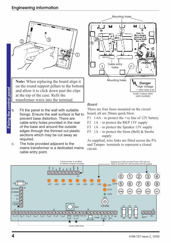
b. Fit the panel to the wall with suitablefixings. Ensure the wall surface is flat toprevent base distortion. There arecable entry holes provided in the rearof the base and around the outsideedges through the thinned out plasticsections which may be cut away asrequired.
c. The hole provided adjacent to themains transformer is a dedicated mainscable entry point.
Board
There are four fuses mounted on the circuitboard, all are 20mm quick blow.
F1 1.6A - to protect the +ve line of 12V battery
F2 1A - to protect the RKP 13V supply
F3 1A - to protect the Speaker 13V supply
F5 1A - to protect the Siren (Bell) & Strobesupply
As supplied, wire links are fitted across the PAand Tamper terminals to represent a closedcircuit.
4 4188-727 issue 2_10/02
Engineering informationF
ixin
gth
eco
ntr
olp
an
el
J2
PA+
TAMP-
+13V 0V -STROBE
J6
+ - AC
SW1
+ T ASCB
D BBELL
+ -
SET
1A 1A 1.6A
BE
LL/S
TR
OB
E
13V
/S
PE
AK
ER
BA
TT
ER
Y
BATT
J4
F1F3F5
J5
0V
TAMP
+13V
COMMS
SOUND
VR1
VOLUME
21 43 65 87
1A
RKP FUSE
F2
AB
OR
T
J3
+1
3V
L/F
AIL
0V
FIR
E
PA
INT
SE
T
CO
NF
Factory fitted links
0 1 2 3
5 6 7 8
CHIME OMIT RESET
4
9
SETPROG
Communicator is not fittedto Optima compact G3 panel
Keypad and LEDs (except Power LED) are notfitted to Accenta G3 and Accenta mini G3 panels
LD1 LD2 LD3 LD4 LD5 LD6 LD7 LD8 LD9
LD10
LD22
LD18
J1
Mounting holes
Mounting holes
Cable entryholes
DangerHigh Voltage
~ 230V 50Hz 0.2A
FUSE T125mA 250V(ANTI-SURGE)
�
� �
Wiring the system
Caution: Always power-down the panelwhen wiring external circuits, to preventdamage to the panel electronics.
Systematically wire and test each circuit:
� Zone, Tamper circuit and PA circuits
� Finish by wiring any additional extensionspeaker sounders, external siren (bell) /strobe and the 13V supply.
Tamper network
The Tamper circuit is used to protect all cablesand detectors in the system from unauthorisedaccess including the panel and RKP covers.
The zone and PA tampers should be series wiredand connected to the TAMP terminals.Terminals T & A are for the external sirentamper. The TAMP terminals at the bottom leftof the board are for the RKP tampers.
Tamper alarms that occur in the Day modeoperate internal sounders only. Tamper alarms inSet cause a full alarm condition. Tamper isindicated on the control panel and RKPs by theTamper indicator.
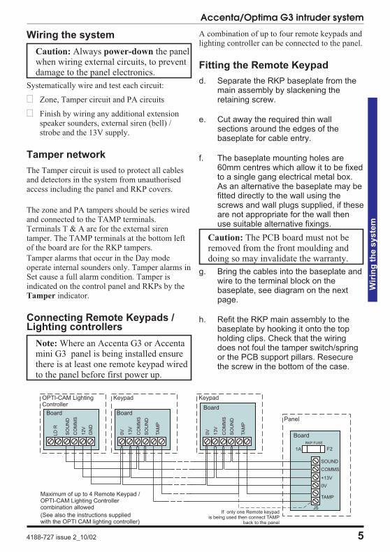
Connecting Remote Keypads /Lighting controllers
Note: Where an Accenta G3 or Accentamini G3 panel is being installed ensurethere is at least one remote keypad wiredto the panel before first power up.
A combination of up to four remote keypads andlighting controller can be connected to the panel.
Fitting the Remote Keypad
d. Separate the RKP baseplate from themain assembly by slackening theretaining screw.
e. Cut away the required thin wallsections around the edges of thebaseplate for cable entry.
f. The baseplate mounting holes are60mm centres which allow it to be fixedto a single gang electrical metal box.As an alternative the baseplate may befitted directly to the wall using thescrews and wall plugs supplied, if theseare not appropriate for the wall thenuse suitable alternative fixings.
Caution: The PCB board must not beremoved from the front moulding anddoing so may invalidate the warranty.
g. Bring the cables into the baseplate andwire to the terminal block on thebaseplate, see diagram on the nextpage.
h. Refit the RKP main assembly to thebaseplate by hooking it onto the topholding clips. Check that the wiringdoes not foul the tamper switch/springor the PCB support pillars. Resecurethe screw in the bottom of the case.
4188-727 issue 2_10/02 5
Accenta/Optima G3 intruder system
Wir
ing
the
syste
m
J5
0V
TAMP
+13V
COMMS
SOUND
1A
RKP FUSE
F2
Panel
BoardSO
UN
D
TA
MP
CO
MM
S
13
V
0V
Keypad
Board
CO
MM
S
12V
SO
UN
D
LD
R
Maximum of up to 4 Remote Keypad /OPTI-CAM Lighting Controllercombination allowed
Board
SO
UN
D
TA
MP
CO
MM
S
13
V
0V
Keypad
Board
GN
D
OPTI-CAM LightingController
(See also the instructions suppliedwith the OPTI CAM lighting controller)
If only one Remote keypadis being used then connect TAMP
back to the panel
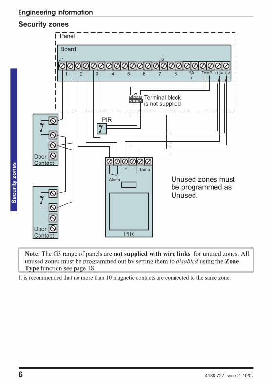
Security zones
Note: The G3 range of panels are not supplied with wire links for unused zones. Allunused zones must be programmed out by setting them to disabled using the Zone
Type function see page 18.
It is recommended that no more than 10 magnetic contacts are connected to the same zone.
6 4188-727 issue 2_10/02
Engineering informationS
ecu
rity
zo
nes
J2
821 43 65 7
Panel
Alarm
+ -
PA+ -
TAMP +13V 0V
PIR
Unused zones mustbe programmed asUnused.
Board
PIR
DoorContact
DoorContact
Terminal blockis not supplied
Tamp
J1
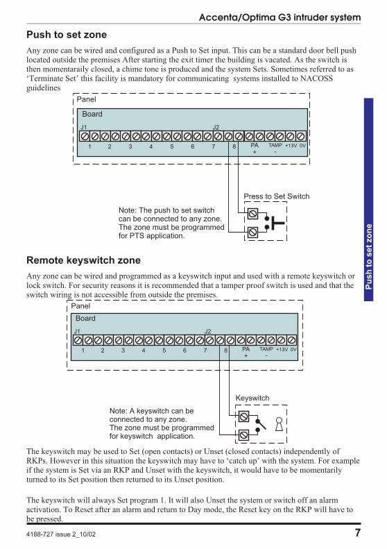
Push to set zone
Any zone can be wired and configured as a Push to Set input. This can be a standard door bell pushlocated outside the premises After starting the exit timer the building is vacated. As the switch isthen momentaraily closed, a chime tone is produced and the system Sets. Sometimes referred to as‘Terminate Set’ this facility is mandatory for communicating systems installed to NACOSSguidelines
Remote keyswitch zone
Any zone can be wired and programmed as a keyswitch input and used with a remote keyswitch orlock switch. For security reasons it is recommended that a tamper proof switch is used and that theswitch wiring is not accessible from outside the premises.
The keyswitch may be used to Set (open contacts) or Unset (closed contacts) independently ofRKPs. However in this situation the keyswitch may have to ‘catch up’ with the system. For exampleif the system is Set via an RKP and Unset with the keyswitch, it would have to be momentarilyturned to its Set position then returned to its Unset position.
The keyswitch will always Set program 1. It will also Unset the system or switch off an alarmactivation. To Reset after an alarm and return to Day mode, the Reset key on the RKP will have tobe pressed.
4188-727 issue 2_10/02 7
Accenta/Optima G3 intruder system
Pu
sh
toset
zo
ne
J2
821 43 65 7 PA+ -
TAMP +13V 0V
Board
J1
Panel
Keyswitch
Note: A keyswitch can beconnected to any zone.The zone must be programmedfor keyswitch application.
J2
821 43 65 7 PA+ -
TAMP +13V 0V
Board
J1
Panel
Press to Set Switch
Note: The push to set switchcan be connected to any zone.The zone must be programmedfor PTS application.
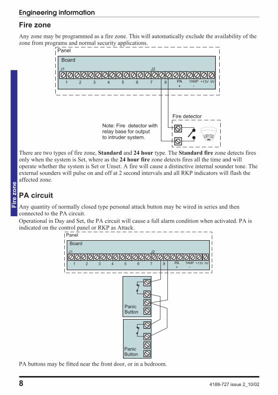
Fire zone
Any zone may be programmed as a fire zone. This will automatically exclude the availability of thezone from programs and normal security applications.
There are two types of fire zone, Standard and 24 hour type. The Standard fire zone detects firesonly when the system is Set, where as the 24 hour fire zone detects fires all the time and willoperate whether the system is Set or Unset. A fire will cause a distinctive internal sounder tone. Theexternal sounders will pulse on and off at 2 second intervals and all RKP indicators will flash theaffected zone.
PA circuit
Any quantity of normally closed type personal attack button may be wired in series and thenconnected to the PA circuit.
Operational in Day and Set, the PA circuit will cause a full alarm condition when activated. PA isindicated on the control panel or RKP as Attack.
PA buttons may be fitted near the front door, or in a bedroom.
8 4188-727 issue 2_10/02
Engineering informationF
ire
zo
ne
J2
821 43 65 7 PA+ -
TAMP +13V 0V
Board
J1
Panel
Fire detector
Note: Fire detector withrelay base for outputto intruder system.
J2
821 43 65 7 PA+ -
TAMP +13V 0V
Board
J1
Panel
PanicButton
PanicButton
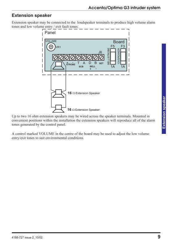
Extension speaker
Extension speaker may be connected to the loudspeaker terminals to produce high volume alarmtones and low volume entry / exit fault tones.
Up to two 16 ohm extension speakers may be wired across the speaker terminals. Mounted inconvenient positions within the installation the extension speakers will reproduce all of the alarmtones generated by the control panel.
A control marked VOLUME in the centre of the board may be used to adjust the low volumeentry/exit tones to suit environmental conditions.
4188-727 issue 2_10/02 9
Accenta/Optima G3 intruder system
Exte
nsio
nsp
eaker
-STROBE
J6
+ T ASCB
D BBELL
+ -
SET
1A
BE
LL
/ST
RO
BE
F5
Panel
Board
1A
13
VS
PE
AK
ER
F3
16 � Extension Speaker
16 � Extension Speaker
VR1
VOLUME
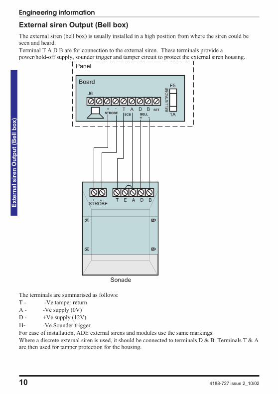
External siren Output (Bell box)
The external siren (bell box) is usually installed in a high position from where the siren could beseen and heard.
Terminal T A D B are for connection to the external siren. These terminals provide apower/hold-off supply, sounder trigger and tamper circuit to protect the external siren housing.
The terminals are summarised as follows:
T - -Ve tamper return
A - -Ve supply (0V)
D - +Ve supply (12V)
B- -Ve Sounder trigger
For ease of installation, ADE external sirens and modules use the same markings.
Where a discrete external siren is used, it should be connected to terminals D & B. Terminals T & Aare then used for tamper protection for the housing.
10 4188-727 issue 2_10/02
Engineering informationE
xte
rnalsir
en
Ou
tpu
t(B
ell
bo
x)
-STROBE
J6
+ T ASCB
D BBELL
+ -
SET
1A
BE
LL
/ST
RO
BE
F5
Sonade
Panel
Board
+ - T E A D BSTROBE
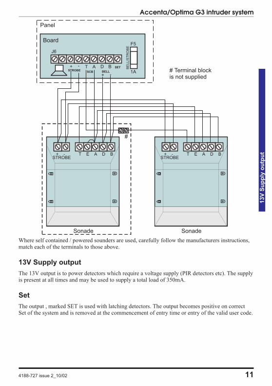
Where self contained / powered sounders are used, carefully follow the manufacturers instructions,match each of the terminals to those above.
13V Supply output
The 13V output is to power detectors which require a voltage supply (PIR detectors etc). The supplyis present at all times and may be used to supply a total load of 350mA.
Set
The output , marked SET is used with latching detectors. The output becomes positive on correctSet of the system and is removed at the commencement of entry time or entry of the valid user code.
4188-727 issue 2_10/02 11
Accenta/Optima G3 intruder system
13V
Su
pp
lyo
utp
ut
# Terminal blockis not supplied
-STROBE
J6
+ T ASCB
D BBELL
+ -
SET
1A
BE
LL/S
TR
OB
E
F5
Sonade
Panel
Board
+ - T E A D BSTROBE
#
Sonade
+ - T E A D BSTROBE
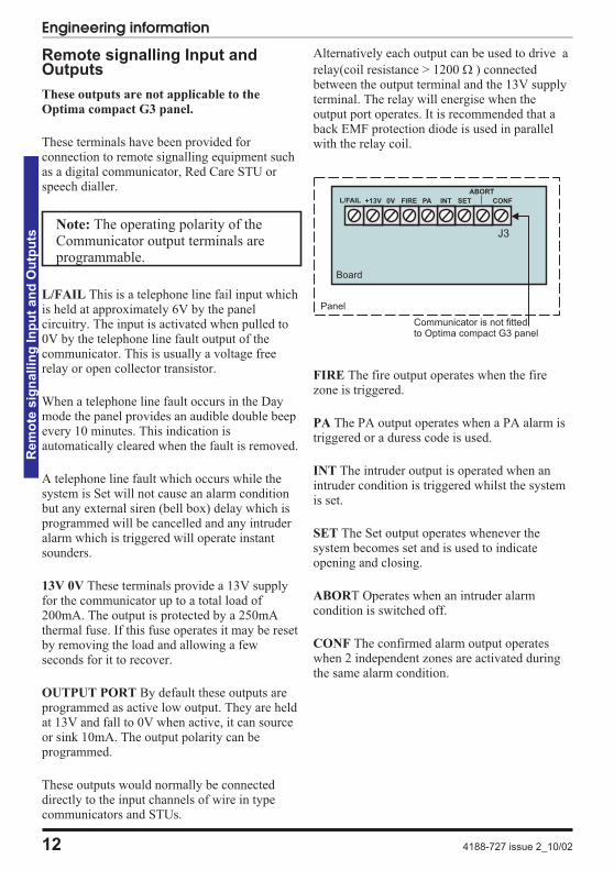
Remote signalling Input andOutputs
These outputs are not applicable to the
Optima compact G3 panel.
These terminals have been provided forconnection to remote signalling equipment suchas a digital communicator, Red Care STU orspeech dialler.
Note: The operating polarity of theCommunicator output terminals areprogrammable.
L/FAIL This is a telephone line fail input whichis held at approximately 6V by the panelcircuitry. The input is activated when pulled to0V by the telephone line fault output of thecommunicator. This is usually a voltage freerelay or open collector transistor.
When a telephone line fault occurs in the Daymode the panel provides an audible double beepevery 10 minutes. This indication isautomatically cleared when the fault is removed.
A telephone line fault which occurs while thesystem is Set will not cause an alarm conditionbut any external siren (bell box) delay which isprogrammed will be cancelled and any intruderalarm which is triggered will operate instantsounders.
13V 0V These terminals provide a 13V supplyfor the communicator up to a total load of200mA. The output is protected by a 250mAthermal fuse. If this fuse operates it may be resetby removing the load and allowing a fewseconds for it to recover.
OUTPUT PORT By default these outputs areprogrammed as active low output. They are heldat 13V and fall to 0V when active, it can sourceor sink 10mA. The output polarity can beprogrammed.
These outputs would normally be connecteddirectly to the input channels of wire in typecommunicators and STUs.
Alternatively each output can be used to drive a
relay(coil resistance > 1200 � ) connectedbetween the output terminal and the 13V supplyterminal. The relay will energise when theoutput port operates. It is recommended that aback EMF protection diode is used in parallelwith the relay coil.
FIRE The fire output operates when the firezone is triggered.
PA The PA output operates when a PA alarm istriggered or a duress code is used.
INT The intruder output is operated when anintruder condition is triggered whilst the systemis set.
SET The Set output operates whenever thesystem becomes set and is used to indicateopening and closing.
ABORT Operates when an intruder alarmcondition is switched off.
CONF The confirmed alarm output operateswhen 2 independent zones are activated duringthe same alarm condition.
12 4188-727 issue 2_10/02
Engineering informationR
em
ote
sig
nallin
gIn
pu
tan
dO
utp
uts
ABORT
J3
+13VL/FAIL 0V FIRE PA INT SET CONF
Communicator is not fittedto Optima compact G3 panel
Panel
Board
Important Notes
a. Each output has been configured asactive low and will normally require theEPROM or NVM for the communicatoror STU to be programmed as activelow or positive removed. Howeverthere may be differences betweensome pieces of equipment and someAlarm Receiving Centres (ARCs).
b. Where the communicator is poweredfrom an external source, not the paneland the outputs are being used withoutrelays, the panel and external powersupply will require a commonednegative supply rail.
c. If the communicator is not fitted insidethe panel and abort is being used, careshould be taken to ensure that theabort connection cannot be damagedor severed as this could cause theARC to incorrectly filter an alarmsignal.
d. It is very important that communicatingsystems are fully tested and that allsignals are correctly received at theARC when the system is installed andserviced.
Filtering of Intruder alarmsA condition of most police Force Policies andunder the guidance of NACOSS NACP 14(Code of Practice for intruder Alarm SystemsSignalling to Alarm Receiving Centres) is thatall intruder alarm signals received by an AlarmReceiving Centre (ARC) must be filtered toestablish their validity before passing to thepolice.
The exact method of filtering should be decidedaccording to the regional Police Force Policyand ARC procedures.
In general, the panels offer the followingmethods which could be used to filter an alarm.
Set/Unset A Set or Unset signal which isreceived by the ARC at around the same time asan intruder signal can be used to filter the alarm.
Abort Output The abort output operateswhenever a user code is entered or a keyswitchis used to switch off an intruder alarm condition.When an abort signal is received by ARC at oraround the same time as an intruder signal, thealarm can be filtered.
Restore of the Intruder Output The intruderalarm output is restored to 12V whenever a usercode is entered or a keyswitch is used to switchoff an intruder alarm condition. Where anintruder alarm is shortly followed by a restore atthe ARC, this can be used to filter the alarm.
4188-727 issue 2_10/02 13
Accenta/Optima G3 intruder system
Rem
ote
sig
nallin
gIn
pu
tan
dO
utp
uts
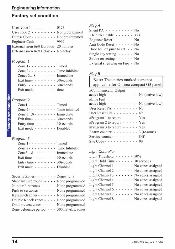
Factory set condition
User code 1 - - - - - - - - 0123
User code 2 - - - - - - - - Not programmed
Duress Code - - - - - - - - Not programmed
Engineer Code - - - - - - - 9999
External siren Bell Duration 20 minutes
External siren Bell Delay - - No delay
Program 1
Zone 1- - - - - - - - - Timed
Zone 2- - - - - - - - - Time Inhibited
Zones 3…8 - - - - - - Immediate
Exit time- - - - - - - - 30seconds
Entry - - - - - - - - - 30seconds
Exit mode - - - - - - - timed
Program 2
Zone1 - - - - - - - - - Timed
Zone 2- - - - - - - - - Time inhibited
Zone 3…8 - - - - - - - Immediate
Exit time- - - - - - - - 30seconds
Entry time - - - - - - - 30seconds
Exit mode - - - - - - - Disabled
Program 3
Zone 1- - - - - - - - - Timed
Zone 2- - - - - - - - - Time Inhibited
Zone3…8 - - - - - - - Immediate
Exit time- - - - - - - - 30seconds
Entry time - - - - - - - 30seconds
Exit mode - - - - - - - Disabled
Security Zones - - - - - - - Zones 1…8
Standard Fire zones - - - - None programmed
24 hour Fire zones - - - - - None programmed
Push to set zones - - - - - - None programmed
Keyswitch zones - - - - - - None programmed
Double Knock zones - - - - None programmed
Omit prevent zones- - - - - None programmed
Zone debounce period - - - 300mS ALL zones
Flag A
Silent PA - - - - - - - - - No
RKP PA Enable - - - - - - Yes
Engineer Reset- - - - - - - No
Anti Code Reset - - - - - - No
Door bell on push to set - - No
Single key setting - - - - - No
Strobe on setting - - - - - - No
External siren Bell on Fire - No
Flag B
Note: The entries marked # are notapplicable for Optima compact G3 panel.
#Communicator Outputactive high - - - - - - - - - - No (active low)
#Line Failactive high - - - - - - - - - - No (active low)
User Reset PA - - - - - - - - No
User Reset Fire - - - - - - - - No
#Program 1 to report - - - - - Yes
#Program 2 to report - - - - - Yes
#Program 3 to report - - - - - Yes
Rearm counter - - - - - - - - 3 (re-arms)
Service counter - - - - - - - - Off
Site Code - - - - - - - - - - - 00
Light Controller
Light Threshold - - - - - - 50%
Light Hold Time - - - - - - 30 seconds
Light Channel 1 - - - - - - No zones assigned
Light Channel 2 - - - - - - No zones assigned
Light Channel 3 - - - - - - No zones assigned
Light Channel 4 - - - - - - No zones assigned
Light Channel 5 - - - - - - No zones assigned
Light Channel 6 - - - - - - No zones assigned
Light Channel 7 - - - - - - No zones assigned
Light Channel 8 - - - - - - No zones assigned
14 4188-727 issue 2_10/02
Engineering informationF
acto
ryset
co
nd
itio
n
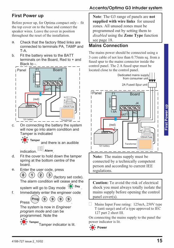
First Power up
Before power up, for Optima compact only - fitthe top cover on to the base and connect thespeaker wires. Leave the cover in positionthroughout the reset of the installation.
a. Check that the factory fitted links areconnected to terminals PA, TAMP andT-A.
b. Fit the battery wires to the BATTterminals on the Board, Red to + andBlack to -.
c. On connecting the battery the systemwill now go into alarm condition andTamper is indicated
and there is an audible
indication. .
d. Fit the cover to hold down the tamperspring at the bottom centre of theboard.
e. Enter the user code, press
(factory set code).The alarm condition will cease and the
system will go to Day mode .
f. Immediately enter the engineer code
Press .
The system is now in Engineerprogram mode and can beprogrammed. Note the
Tamper indicator is lit.
Note: The G3 range of panels are not
supplied with wire links for unusedzones. All unused zones must beprogrammed out by setting them todisabled using the Zone Type functionsee page 18.
Mains Connection
The mains power should be connected using a
3 core cable of not less than 0.75mm sq. from afused spur to the mains connector inside thecontrol panel. The 2 A fused spur must belocated close to the control panel.
Note: The mains supply must beconnected by a technically competentperson and according to current IEEregulations.
Caution: To avoid the risk of electricalshock you must always totally isolate themains supply before opening the controlpanel cover(s).
� Mains Input Fuse rating: 125mA, 250V typeT (anti surge) and of a type approved to IEC127 part 2 sheet III.
On connecting the mains supply to the panel thepower indicator is lit.
4188-727 issue 2_10/02 15
Accenta/Optima G3 intruder system
Fir
st
Po
wer
up
N
LE
Transformer
125mA Fuse
Panel
+ - AC1.6A
BA
TT
ER
Y
BATT
J4
F1 Board
(red)+
Black -
12V battery
Tamper
Alarm
0 1 2 3
Day
Prog 9 9 9 9
Tamper
N
LE
Transformer
125mA Fuse
Panel
+ - AC1.6AB
AT
TE
RY
BATT
J4
F1 Board
(red)+
Black -
12V battery
2A Fused Spur unit
Dedicated mains supplyfrom consumer unit.
Power

Testing the system
Complete the wiring of the system and then:
� Fully test the system and ensure it is faultfree.
� Fully program the system
� Fill in the installation log at the back of themanual and retain if for future reference.
� Finally explain the operation of the systemto the end user. The Operating Instructions
are attached to the centre of this manual.
Detach them and leave them with the
user.
Engineer program mode
The panel may be programmed to suit a widevariety of installations.
Once the engineer program mode has beenaccessed, each configuration may be changed inany order. As each configuration is completedthe system will automatically return to top levelof engineer program mode.
Before entering engineer program mode thesystem should be in the Day mode, with the Dayand Power indicators lit.
Key
To exit operation
System indications
- Unset system indication
- Set system indication
To enter Engineer program mode
Note: The factory configured engineer’saccess code is 9999. If however this codeis changed then enter the appropriatecode.
To Exit Engineer program mode
To reset panel to Factory setconditions
Caution: All configurations of the panelare restored to factory ‘default’conditions.
16 4188-727 issue 2_10/02
Engineering informationT
esti
ng
the
syste
m
Reset
Day
Prog
9 9 9 9
Tamper Day
ZONE 1 - 8Momentarily On
Acknowledge
Power
Day Power
Reset Quit the current functionLeave program menuDown one menu level
LED steady On indication
LED Off
Strobe
External Siren
NOTE: In general a flat beep isan indication of an incorrect key press.
Sound description
Internal sound
External devices
ARCo/p Output to Alarm Receiving Centre
Communicator outputs are not applicable forOptima compact G3 panel
LED flashing indication
reset beeps
Within 5 seconds ofpowering up the panel
Reset Reset
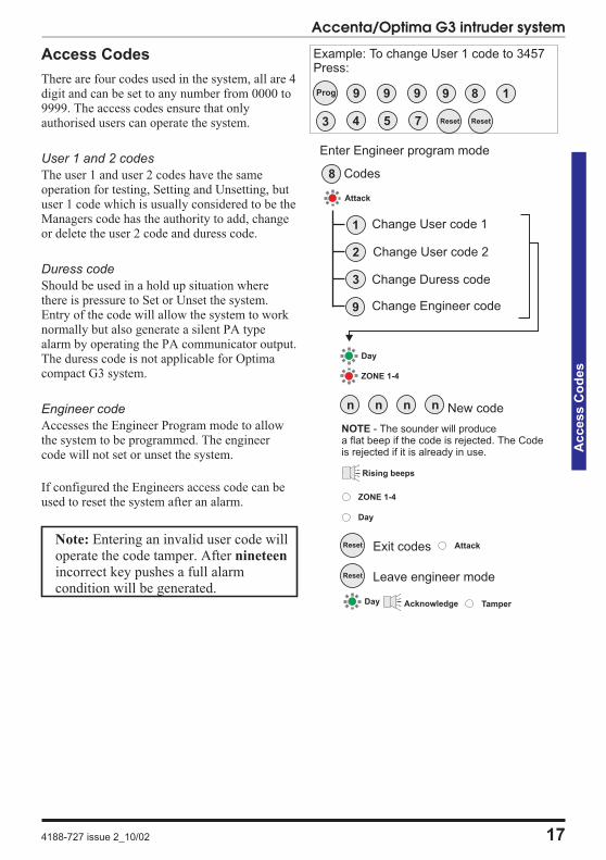
Access Codes
There are four codes used in the system, all are 4digit and can be set to any number from 0000 to9999. The access codes ensure that onlyauthorised users can operate the system.
User 1 and 2 codes
The user 1 and user 2 codes have the sameoperation for testing, Setting and Unsetting, butuser 1 code which is usually considered to be theManagers code has the authority to add, changeor delete the user 2 code and duress code.
Duress code
Should be used in a hold up situation wherethere is pressure to Set or Unset the system.Entry of the code will allow the system to worknormally but also generate a silent PA typealarm by operating the PA communicator output.The duress code is not applicable for Optimacompact G3 system.
Engineer code
Accesses the Engineer Program mode to allowthe system to be programmed. The engineercode will not set or unset the system.
If configured the Engineers access code can beused to reset the system after an alarm.
Note: Entering an invalid user code willoperate the code tamper. After nineteen
incorrect key pushes a full alarmcondition will be generated.
4188-727 issue 2_10/02 17
Accenta/Optima G3 intruder system
Access
Co
des
Reset
Reset
Codes
Change User code 1
Change User code 2
Change Duress code
Change Engineer code
2
3
9
1
8
ZONE 1-4
n n n n New code
ZONE 1-4
Rising beeps
Attack
Exit codes
Leave engineer mode
Day Tamper
Attack
Acknowledge
Day
Day
NOTE - The sounder will producea flat beep if the code is rejected. The Codeis rejected if it is already in use.
Enter Engineer program mode
Example: To change User 1 code to 3457Press:
9Prog 9 9 9
4 Reset Reset
8 1
3 5 7
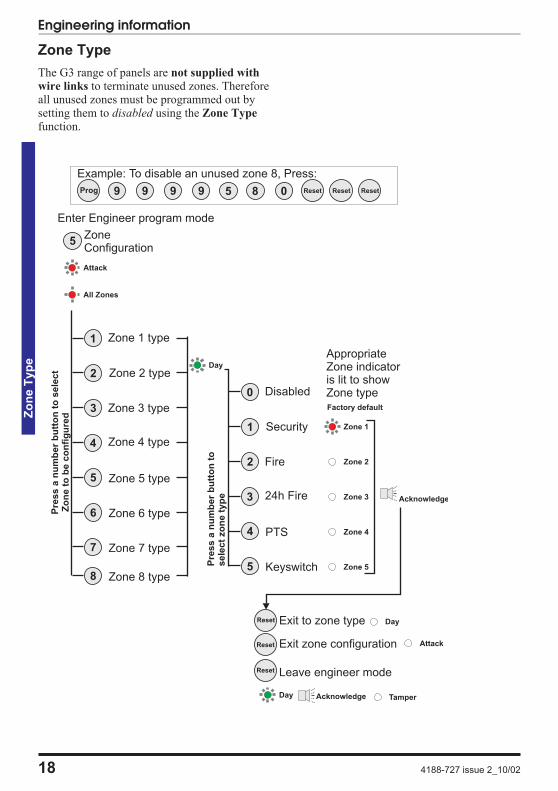
Zone Type
The G3 range of panels are not supplied with
wire links to terminate unused zones. Thereforeall unused zones must be programmed out bysetting them to disabled using the Zone Type
function.
18 4188-727 issue 2_10/02
Engineering informationZ
on
eT
yp
e
ZoneConfiguration
Zone 1 type
Zone 2 type
Zone 3 type
Zone 4 type
Zone 5 type
Zone 6 type
Zone 8 type
5
6
8
2
3
4
1
5
Attack
All Zones
Pre
ss
an
um
be
rb
utt
on
tos
ele
ct
Zo
ne
tob
ec
on
fig
ure
d
Pre
ss
an
um
be
rb
utt
on
tos
ele
ct
zo
ne
typ
e
Day
Exit to zone type
Exit zone configuration
Leave engineer mode
Tamper
Attack
Acknowledge
Day
Disabled
Security
Fire
24h Fire
PTS
Keyswitch
4
5
1
2
3
0
Zone 5
Zone 3
Zone 2
Zone 1
Zone 4
Factory default
AppropriateZone indicatoris lit to showZone type
Acknowledge
Day
Enter Engineer program mode
Reset
Reset
Reset
Zone 7 type7
Example: To disable an unused zone 8, Press:
5Prog 9 9 9 9 0 Reset Reset Reset8
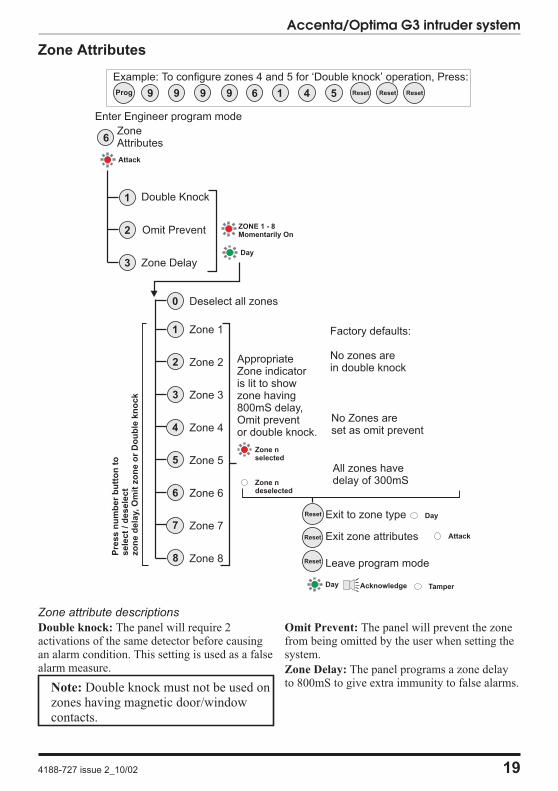
Zone Attributes
Zone attribute descriptions
Double knock: The panel will require 2activations of the same detector before causingan alarm condition. This setting is used as a falsealarm measure.
Note: Double knock must not be used onzones having magnetic door/windowcontacts.
Omit Prevent: The panel will prevent the zonefrom being omitted by the user when setting thesystem.
Zone Delay: The panel programs a zone delayto 800mS to give extra immunity to false alarms.
4188-727 issue 2_10/02 19
Accenta/Optima G3 intruder system
ZoneAttributes
Double Knock
Omit Prevent
Zone Delay
2
3
1
6
Attack
Zone nselected
Zone ndeselected
5
6
7
2
3
4
1
8
Zone 1
Zone 2
Zone 3
Zone 4
Zone 5
Zone 6
Zone 7
Zone 8
Pre
ss
nu
mb
er
bu
tto
nto
sele
ct
/d
esele
ct
zo
ne
dela
y,O
mit
zo
ne
or
Do
ub
lekn
ock
0 Deselect all zones
ZONE 1 - 8Momentarily On
AppropriateZone indicatoris lit to showzone having800mS delay,Omit preventor double knock.
Factory defaults:
No zones arein double knock
No Zones areset as omit prevent
All zones havedelay of 300mS
Day
Enter Engineer program mode
Exit to zone type
Exit zone attributes
Leave program mode
Tamper
Attack
Acknowledge
Day
Day
Reset
Reset
Reset
Example: To configure zones 4 and 5 for ‘Double knock’ operation, Press:
6Prog 9 9 9 9 5 Reset Reset Reset1 4

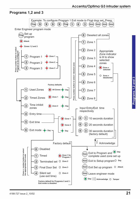
Programs
The panel uses 3 Part Set routines known asPrograms. In each Program the exit mode can bechanged and the zone may be set up to have adifferent function.
The examples below show how 3 typicalPrograms could be used in a house.
� Program 1 : To arm all of the zones andbecome Set as the user leaves the propertyand closes the final door.
� Program 2 : To protect the perimeter of theproperty in the evening and become Set aftersay 20 seconds.
� Program 3 : To protect the downstairs areasof the house at night and become Setinstantly and silently.
Note: The above are purely examples.The installer must program the panel toconfigure all the circuits to thecustomer’s exact requirements.
Zone Function per Program
Timed : This function would be used to protectthe main entry/exit door of the entry route.
Time inhibited : This is a zone which, onsetting the panel, allows access to the Entry /Exit zone. However, if the panel is set and antime inhibited zone is triggered before an Entry/Exit zone then an alarm will be generatedimmediately.
Immediate: This is a zone which will, whenentered, go into alarm when the panel is set.
Unused : A zone that is programmed as anUnused zone by the Engineer, then is ignored bythe panel. Primarily used for Part set options.
Exit Modes program
Timed A timed Program will become Set as theExit timer expires.
Terminated Set
This sets an infinite time out, which will only setonce the PTS input is operated.
Final Door A final door program will be Set5 seconds after a timed zone has opened andclosed.
Silent Set This operates exactly the same as‘Timed’ but completely silent without theinternal sounder signal.
Note: If a program is not selected whenthe user Sets the system, Program 1 willautomatically Set. Therefore Program 1is usually considered as the Full SetProgram containing all of the zones.
20 4188-727 issue 2_10/02
Engineering informationP
rog
ram
s
Programs 1,2 and 3
4188-727 issue 2_10/02 21
Accenta/Optima G3 intruder system
Pro
gra
ms
1,2
an
d3
Reset
Reset
ProgSet upprogram
Program 1
2
3
1
Program 2
Program 3
Used Zones
Timed Zones
Time inhibitzones
Exit time
Exit mode
5
6
2
3
4
1
Disabled
Terminated set
Final Door Set
Silent set(use exit time)
2
3
4
0
Attack
Zone 1
Zone 2
Zone 3
Pre
ss
nu
mb
er
bu
tto
nto
sele
ct
Pro
gra
mto
be
co
nfi
gu
red
All Zones
Zone 2
Zone 1
Zone 2
Entry time
Day
Factory default
Zone 4
Zone 3
Zone 2
Pre
ss
an
um
ber
bu
tto
nto
sele
ct
the
ap
pro
pri
ate
Exit
mo
de
Day
Zone 1 Day
Day
Day
Input Entry/Exit timerespectively
0 1
0 2
0 3
20 seconds duration
Acknowledge
10 seconds duration
30 seconds duration(factory default)
Zone nselected
Zone ndeselected
5
6
7
2
3
4
1
8
Zone 1
Zone 2
Zone 3
Zone 4
Zone 5
Zone 6
Zone 7
Zone 8
AppropriateZone indicatoris lit to showselectedzones
Pre
ss
nu
mb
er
bu
tto
nto
sele
ct
/d
esele
ct
zo
ne
0 Deselect all zones
Factory defaults
Leave engineer mode
Day Tamper
Attack
Acknowledge
Exit to Setup program
Exit Set up program
Exit to Program andcomplete used zone set up
Day
Day
Zones 1,2 and 3
Enter Engineer program mode
Timed1 Zone 1 forProgram 1
Factory default for Programs 2 and 3 :Exit mode is disabled
Reset
Reset
Example: To configure Program 1 Exit mode to Final door set, Press:
Prog 1Prog 9 9 9 9 3 Reset Reset ResetReset6
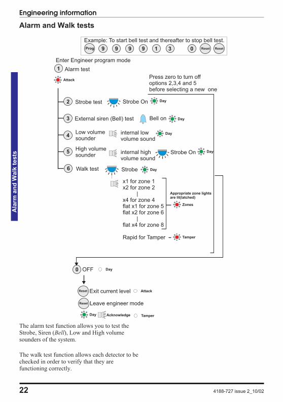
Alarm and Walk tests
The alarm test function allows you to test theStrobe, Siren (Bell), Low and High volumesounders of the system.
The walk test function allows each detector to bechecked in order to verify that they arefunctioning correctly.
22 4188-727 issue 2_10/02
Engineering informationA
larm
an
dW
alk
tests
Alarm test1
Attack
x1 for zone 1x2 for zone 2
|x4 for zone 4flat x1 for zone 5flat x2 for zone 6
|flat x4 for zone 8
Rapid for Tamper
Zones
Strobe
Strobe test2
External siren (Bell) test3
Low volumesounder
High volumesounder
4
5
Walk test6
Strobe On
Bell on
internal lowvolume sound
internal highvolume sound
Strobe On
Day
Day
Day
Day
Day
OFF0 Day
Exit current level
Leave engineer mode
Day Tamper
Attack
Acknowledge
Appropriate zone lightsare lit(latched)
Tamper
Press zero to turn offoptions 2,3,4 and 5before selecting a new one
Enter Engineer program mode
Reset
Reset
Example: To start bell test and thereafter to stop bell test.
3Prog 9 9 9 9 0 Reset1 Reset
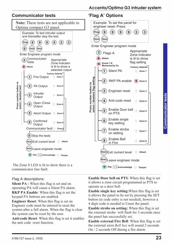
Communicator tests
Note: These tests are not applicable toOptima compact G3 panel.
The Zone 8 LED is lit to show there is acommunicator line fault.
‘Flag A’ Options
4188-727 issue 2_10/02 23
Accenta/Optima G3 intruder system
Co
mm
un
icato
rte
sts
CommunicatorTests
Fire Output
2 PA Output
3IntruderOutput
Open /CloseOutput
4
5 Abort Output
ConfirmedOutput
6
1
2
Attack
Zone 1
Zone 2
Zone 3
Zone 4
Zone 5
Zone 6
0 Stop the tests
Pre
ss
nu
mb
er
bu
tto
nto
sele
ct
/d
esele
ct
test
AppropriateZone indicatoris lit to show aselected output
Factory defaults
Exit current level
Leave engineer mode
Day Tamper
Attack
Acknowledge
Zone 8Communicator fault
Enter Engineer program mode
Reset
Reset
Example: To test intruder outputand thereafter stop the test.
3Prog 9 9 9 9
0 Reset
2
Reset
Flag A descriptions:
Silent PA : When this flag is set and onoperating PA will cause a Silent PA alarm.
RKP PA Enable: When this flag is set thekeypad PA buttons are enabled.
Engineer Reset: When this flag is set anEngineer code must be entered to reset thesystem after a full alarm. When the flag is clearthe system can be reset by the user.
Anti-code Reset: When this flag is set it enablesthe anti code reset function.
Enable Door bell on PTS: When this flag is setit allows a zone circuit programmed as PTS tooperate as a door bell.
Enable single key setting:When this flag is setit allows the panel to be set by pressing the SETbutton (ie code entry is not needed), however a4 digit code is needed to Unset the panel.
Enable strobe on setting: When this flag is setthe external strobe will flash for 3 seconds oncethe panel has successfully set.
Enable external Fire Bell: When this flag is setthe external siren Bell box will sound 2 secondsOn / 2 seconds Off during a fire alarm.
Zone 1
Zone 2
Zone 3
Zone 4
Zone 5
Zone 6
Zone 7
Zone 8
Flags A
Silent PA
RKP PA enable
Engineer reset
Anti-code reset
Enable Door bellon PTS
5
Enable singlekey setting
6
Enable strobeon setting
7
2
3
4
1
Enable Bellin Fire
8
3
Attack
Factory defaults
AppropriateZone indicatoris lit to showflag setting
Exit current level
Leave engineer mode
Day Tamper
Attack
Acknowledge
Zones 1-8Momentarily On
Pre
ss
nu
mb
er
bu
tto
nto
sele
ct
/d
esele
ct
flag
sett
ing
Enter Engineer program mode
Reset
Reset
Example: To set the panel forengineer reset, Press:
3Prog 9 9 9 9
Reset
3
Reset
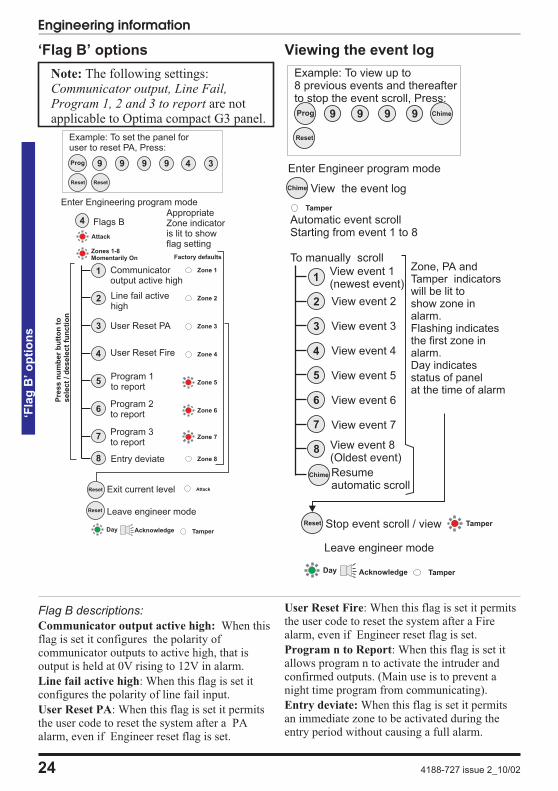
‘Flag B’ options
Note: The following settings:Communicator output, Line Fail,Program 1, 2 and 3 to report are notapplicable to Optima compact G3 panel.
Viewing the event log
24 4188-727 issue 2_10/02
Engineering information‘F
lag
B’o
pti
on
s
Flags B
Communicatoroutput active high
Line fail activehigh
User Reset PA
User Reset Fire
Program 1to report
Program 2to report
Program 3to report
5
6
7
2
3
4
1
4
Factory defaults
Zone 1
Zone 2
Zone 3
Zone 4
Zone 5
Zone 6
Zone 7
Attack
AppropriateZone indicatoris lit to showflag setting
Exit current level
Leave engineer mode
Day Tamper
Attack
Acknowledge
Zones 1-8Momentarily On
Entry deviate8 Zone 8
Pre
ss
nu
mb
er
bu
tto
nto
sele
ct
/d
esele
ct
fun
cti
on
Enter Engineering program mode
Reset
Reset
Example: To set the panel foruser to reset PA, Press:
3Prog 9 9 9 9
Reset
4
Reset
Flag B descriptions:
Communicator output active high: When thisflag is set it configures the polarity ofcommunicator outputs to active high, that isoutput is held at 0V rising to 12V in alarm.
Line fail active high: When this flag is set itconfigures the polarity of line fail input.
User Reset PA: When this flag is set it permitsthe user code to reset the system after a PAalarm, even if Engineer reset flag is set.
User Reset Fire: When this flag is set it permitsthe user code to reset the system after a Firealarm, even if Engineer reset flag is set.
Program n to Report: When this flag is set itallows program n to activate the intruder andconfirmed outputs. (Main use is to prevent anight time program from communicating).
Entry deviate: When this flag is set it permitsan immediate zone to be activated during theentry period without causing a full alarm.
Reset
View the event logChime
5
6
7
2
3
4
1
8
View event 1(newest event)
View event 2
View event 3
View event 4
View event 5
View event 6
View event 7
View event 8(Oldest event)
Automatic event scrollStarting from event 1 to 8
To manually scroll
Resumeautomatic scroll
Zone, PA andTamper indicatorswill be lit toshow zone inalarm.Flashing indicatesthe first zone inalarm.Day indicatesstatus of panelat the time of alarm
Leave engineer mode
Stop event scroll / view
Tamper
Day TamperAcknowledge
Tamper
Enter Engineer program mode
Chime
Example: To view up to8 previous events and thereafterto stop the event scroll, Press:
ChimeProg 9 9 9 9
Reset
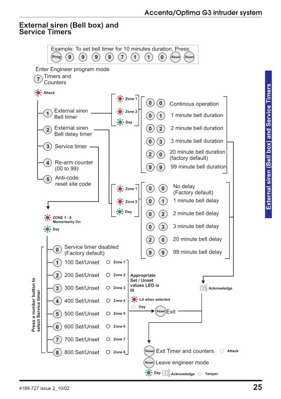
External siren (Bell box) andService Timers
4188-727 issue 2_10/02 25
Accenta/Optima G3 intruder system
Exte
rnalsir
en
(Bell
bo
x)
an
dS
erv
ice
Tim
ers
Reset
Reset
Reset
Anti-codereset site code
Zone 1
Zone 2
0 0
0 1
0 2
0 3
2 0
Continous operation
1 minute bell duration
3 minute bell duration
20 minute bell duration(factory default)
9 9 99 minute bell duration
2 minute bell duration
Zone 1
Zone 2
0 0
0 1
0 2
0 3
2 0
No delay(Factory default)
1 minute bell delay
3 minute bell delay
20 minute bell delay
9 9 99 minute bell delay
2 minute bell delay
Acknowledge
100 Set/Unset1 Zone 1
Pre
ss
an
um
ber
bu
tto
nto
sele
ct
Serv
ice
tim
er 300 Set/Unset3 Zone 3
200 Set/Unset2 Zone 2
500 Set/Unset5 Zone 5
400 Set/Unset4 Zone 4
600 Set/Unset6 Zone 6
800 Set/Unset8 Zone 8
700 Set/Unset7 Zone 7
Service timer disabled(Factory default)
0
Lit when selected
Timers andCounters
External sirenBell timer
External sirenBell delay timer
Service timer
Re-arm counter(00 to 99)
2
3
4
1
5
7
Attack
Leave engineer mode
Exit Timer and counters
ZONE 1 - 8Momentarily On
AppropriateSet / Unsetvalues LED islit
Exit
Day
Day
Day
Attack
Day TamperAcknowledge
Day
Enter Engineer program mode
Example: To set bell timer for 10 minutes duration, Press:
7Prog 9 9 9 9 0 Reset Reset1 1
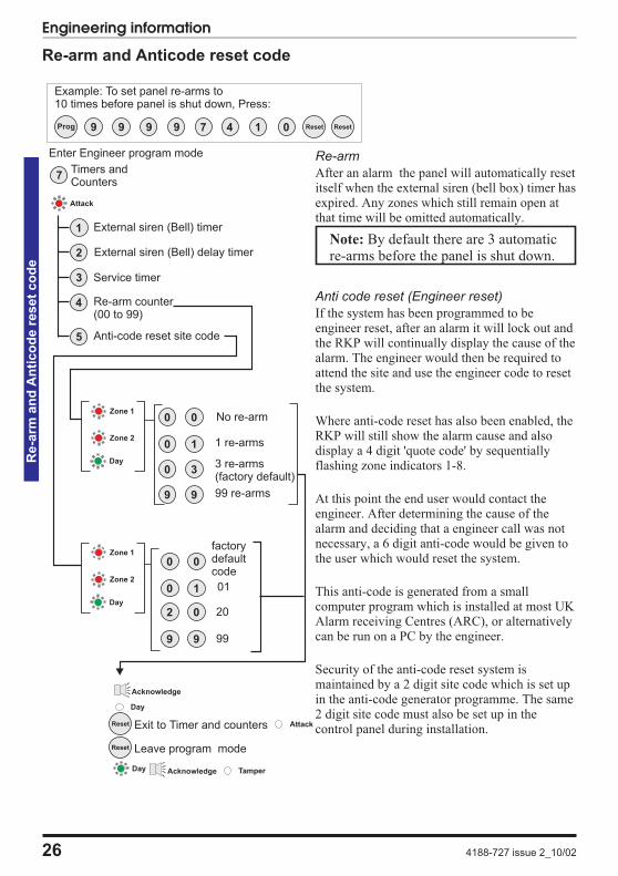
Re-arm and Anticode reset code
Re-arm
After an alarm the panel will automatically resetitself when the external siren (bell box) timer hasexpired. Any zones which still remain open atthat time will be omitted automatically.
Note: By default there are 3 automaticre-arms before the panel is shut down.
Anti code reset (Engineer reset)
If the system has been programmed to beengineer reset, after an alarm it will lock out andthe RKP will continually display the cause of thealarm. The engineer would then be required toattend the site and use the engineer code to resetthe system.
Where anti-code reset has also been enabled, theRKP will still show the alarm cause and alsodisplay a 4 digit 'quote code' by sequentiallyflashing zone indicators 1-8.
At this point the end user would contact theengineer. After determining the cause of thealarm and deciding that a engineer call was notnecessary, a 6 digit anti-code would be given tothe user which would reset the system.
This anti-code is generated from a smallcomputer program which is installed at most UKAlarm receiving Centres (ARC), or alternativelycan be run on a PC by the engineer.
Security of the anti-code reset system ismaintained by a 2 digit site code which is set upin the anti-code generator programme. The same2 digit site code must also be set up in thecontrol panel during installation.
26 4188-727 issue 2_10/02
Engineering informationR
e-a
rman
dA
nti
co
de
reset
co
de
Reset
Reset
Anti-code reset site code
Zone 1
Zone 2
Acknowledge
0 0
0 1
2 0
factorydefaultcode
01
20
9 9 99
Timers andCounters
External siren (Bell) timer
External siren (Bell) delay timer
Service timer
Re-arm counter(00 to 99)
2
3
4
1
5
7
Attack
Day
0 0
0 1
0 3
No re-arm
1 re-arms
3 re-arms(factory default)
9 9 99 re-arms
Leave program mode
Attack
Day TamperAcknowledge
Day
Zone 1
Zone 2
Day
Enter Engineer program mode
Exit to Timer and counters
Example: To set panel re-arms to10 times before panel is shut down, Press:
7Prog 9 9 9 9 0 Reset Reset4 1
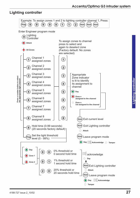
Lighting controller
4188-727 issue 2_10/02 27
Accenta/Optima G3 intruder system
Lig
hti
ng
co
ntr
oller
Prog
Reset
Reset
Reset
Reset
Reset
LightingController
Channel 1assigned zones
5
6
7
2
3
4
1
Channel 2assigned zones
Channel 3assigned zones
Channel 4assigned zones
Channel 5assigned zones
Channel 6assigned zones
Channel 7assigned zones
Channel 8assigned zones
8
Set the light thresholdlevel (0 - 99%)
Hold time(20 seconds factory default)
(0-99 seconds)
9
9
Pre
ss
an
um
ber
bu
tto
nto
sele
ct
the
ap
pro
pri
ate
lig
ht
ch
an
nel
All Zones
5
6
7
2
3
4
1
8
To assign zones to channelpress to select andagain to deselect zone(Factory default: No zonesare selected)
Zone nassigned to the channel
Zone nnot assigned to the channel
AppropriateZone indicatoris lit to identifyits assignment tochannel
Exit Lighting controller
Exit current level
Leave program mode
Day Tamper
Attack
Acknowledge
Day
Attack
Zone 1
Zone 2
Day
0 0
0 1
2 0
0% threshold or0 second hold time acknowledge
20% threshold or20 seconds hold time
1% threshold or1 second hold time
Day
Exit Lighting controller
Leave program mode
Day
Tamper
Attack
Acknowledge
Enter Engineer program mode
Example: To assign zones 1 and 2 to lighting controller channel 1, Press:
9Prog 9 9 9 9 2 Reset Reset Reset1 1
Faults
Fault conditions are often the result of minorinstallation errors or misinterpretation of theequipment being installed. The following pointsoutline the most common installation andcommissioning faults.
a. As supplied the user code is 0123 andthe engineer code is 9999. Both codeswill revert back to these default settingson clearing the NVM.
b. The Engineer Program is accesseddirectly from Day mode via theengineer code.
c. If a tamper, PA or 24Hr fire fault ispresent on the system, it will go to alock out condition (showing theappropriate indication). The keypad willnot produce any audible responsesand the system will not operate untilthe fault has been found and rectified.
d. The most common cause of a zone notresponding to detection is incorrectwiring. Normally closed detectors mustbe wired together in a series loopbefore connecting into the appropriateZONE terminals. Tampers are serieswired in the same manner.
e. Where a permanent zone fault isshowing and the loop resistance isfound to be in order, the most probablecause is a short circuit between thezone wiring and the tamper wiring.When measured with a multimeter theseries resistance between the zoneand tamper wiring should be infinitelyhigh.
f. If totally lost as to the cause of a fault,remove ALL wiring from the Board.Refit the 4-links and test the system.Never fit links to any positions otherthan those marked on the Board.
g. Before testing or replacing any fuses,ALL power must be removed. Fuseswhich fail continually are almostcertainly the result of a short circuit orlow resistance across the 13V supplyor external siren (bell box) supply(terminal D).
Whenever working close to the mainssupply or connector, you shouldexercise extreme caution.Always isolate the mains supply beforeremoving the control panel covers.
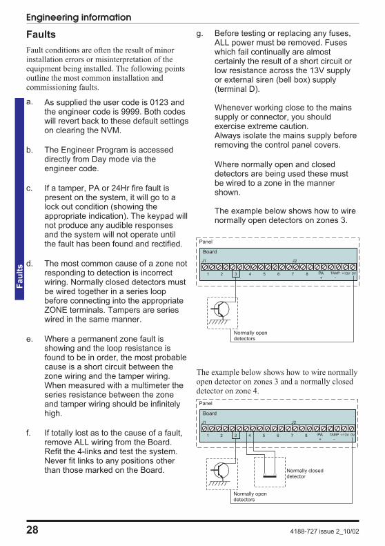
Where normally open and closeddetectors are being used these mustbe wired to a zone in the mannershown.
The example below shows how to wirenormally open detectors on zones 3.
The example below shows how to wire normallyopen detector on zones 3 and a normally closeddetector on zone 4.
28 4188-727 issue 2_10/02
Engineering informationF
au
lts
J2
821 43 65 7 PA+ -
TAMP +13V 0V
Board
J1
Panel
Normally opendetectors
J2
821 43 65 7 PA+ -
TAMP +13V 0V
Board
J1
Panel
Normally opendetectors
Normally closeddetector
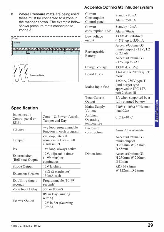
h. Where Pressure mats are being usedthese must be connected to a zone inthe manner shown. The example belowshows pressure mats connected tozones 3.
Specification
Indicators onControl panel orRKPs
Zone 1-8, Power, Attack,Tamper and Day
8 Zones+ve loop, programmablefunction in each program
Tamper-ve loop, internalsounders in Day – Fullalarm in Set
PA +ve loop, always active
External siren(Bell box) Output
12V, adjustable timer(1-99 mins) orcontinuous
Strobe Output 12V latching
Extension Speaker16 � (2 maximum)130mA each
Exit/Entry timersseconds
Programmable (10-99seconds)
Zone Input Delay 300 or 800mS
Set +ve Output
0V in Day (sinking40mA)
12V in Set (Sourcing10mA)
CurrentConsumptionControl panel
Standby 80mA
Alarm 250mA
Currentconsumption RKP
Standby 40mA
Alarm 70mA
Low voltageoutput
13.8V dc stabilised
( 5%) up to 350mA
RechargeableBattery
Accenta/Optima G3mini/compact - 12V, 1.2or 2.1Ah
Accenta/Optima G3- 12V, up to 7Ah
Charge Voltage 13.8V dc ( 5%)
Board Fuses1.6A & 1A 20mm quickblow
Mains Input fuse
125mA, 250V type T(anti-surge) typeapproved to IEC 127,part 2 sheet III
Total CurrentOutput
1A when supported by afully charged battery
Mains SupplyVoltage
230V ( 10%) 50Hz maxload 0.2A
AmbientOperatingtemperature
0 C to 40 C
Enclosureconstruction
3mm Polycarbonate
Dimensions
Accenta/Optima G3mini/compactH 200mm W 253mmD 55mm
Accenta/Optima G3H 230mm W 290mmD 80mm
RKP H 85mmW 122mm D 28mm
4188-727 issue 2_10/02 29
Accenta/Optima G3 intruder system
Sp
ecif
icati
on
J2
821 43 65 7 PA+ -
TAMP +13V 0V
Board
J1
Panel
Pressure Mats
Engineering information
30 4188-727 issue 1_10/02
Index
!13V Supply . . . 11
24 hour fire zone . 2,8,14,18
3 Part Set . . . . 20
AAC terminals . . . 3
Access Codes. . . 17
Alarm test . . . . 22
Anti Code Reset . 14,23,26
ARC . . . . . . . 13
BBattery . . . . . . 15,29
Bell in fire . . . . 23
Board . . . . . . . 4
BS 4737 1986/87 . 1
CCharge Voltage. . 29
Chime . . . . . . 2
Codes . . . . . . . 2
Communicator . . 23
CommunicatorOutputs . . . . . 12,14
CurrentConsumption . . 29
DDay mode . . . . 15
Detectors . . . . . 3
Dimensions. . . . 29
Door bell . . . . . 14,23
Double knock . . 14,19
Duress Code . . . 14,17
EEngineer Code . . 14,17
Engineerprogram mode . . 16,28
Engineer Reset . . 14,23
Entry deviate . . . 24
Entry time . . . . 14,21
Event log . . . . . 24
Exit Mode . . . . 14,20,21
Exit time . . . . . 14,21
Exit/Entrytimers . . . . . . 29
Extension speakers 9
External bellon Fire . . . . . . 14
External siren(Bell) Delay . . . 14
External siren (Bell)Duration . . . . . 14
External siren(Bell) Output. . . 29
External siren(bell) test. . . . . 22
External siren(Bell) timer . . . 25
External siren -Bell- Output . . . 10
FFactory setconditions . . . . 14,16
Faults . . . . . . . 28
Final door set . . . 20,21
Fire zone . . . . . 8,18
Flag A . . . . . . 23
Flag B . . . . . . 24
Full Set . . . . . . 20
Fuses . . . . . . . 4,28
HHigh volumesounder test. . . . 22
Hold time. . . . . 27
IImmediate zone . 20
KKeyswitch zone . 14,18
Llight channel . . . 27
Light Hold Time . 14
Light threshold . . 14,27
Lighting controller 2,14,27
Line Fail . . . . . 14
Local Authorit . . 3
Low volumesounder test . . . 22
MMains . . . . . . . 15,29
Managers code . . 17
NNACOSS . . . . . 7,13
NACP 14 . . . . . 13
Normally closeddetectors . . . . . 28
normally opendetectors . . . . . 28
NVM . . . . . . . 2,13
OOmit prevent . . . 14,19
Operatingtemperature . . . 29
PPA . . . . . . . . 2,8,29
PA fault. . . . . . 28
Pressure mats . . . 29
Program 1 . . . . 14,20
Program 1to report . . . . . 14,24
Program 2 . . . . 14,20
Program 2to report . . . . . 14,24
Program 3 . . . . 14,20
Program 3to report . . . . . 14,24
Programs1,2 and 3 . . . . . 21
PTS zone . . . . . 2,18
Push to Set . . . . 7,14
QQuick set . . . . . 2
quote code . . . . 26
RRe-arm . . . . . . 26
Rearm counter . . 14
Red Care STU . . 2,12
Remote keypad . . 2,5
Remote keyswitch 7
RKP . . . . . . . 3,5,14,29
RKP PA enable. . 23
SSecurity Zones . . 6,14,18
Service counter . . 14
Service timer . . . 25
Set . . . . . . . . 11
Set system . . . . 16
Silent PA . . . . . 14,23
Silent Set . . . . . 20,21
Single key setting 14,23
Site Code . . . . . 14
Speakers . . . . . 3
Specification . . . 29
Standard Fire zone 8,14
Strobe on setting . 14,23
Strobe test . . . . 22
TT A D B . . . . . 10
Tamper . . . . . . 29
Tamper fault . . . 28
Tamper network . 8
Terminated Set . . 7,20,21
Time inhibitedzone . . . . . . . 20,21
Timed. . . . . . . 20
Timed exit . . . . 21
Timed zones . . . 21
Total current . . . 3
UUnset system . . . 16
Unused zone . . . 20,21
User code 1 . . . 14
User 1 . . . . . . 2
User 1 and 2 codes 17
User 2 . . . . . . 2
User code 2. . . . 14
User reset fire . . 14,24
User reset PA. . . 14,24
VVolume . . . . . . 9
WWalk Test . . . . 2,22
wire links . . . . . 4
ZZone Attributes. . 19
Zone debounce . . 14
zone delay . . . . 19
Zone Input Delay. 29
Zone Type . . . . 18
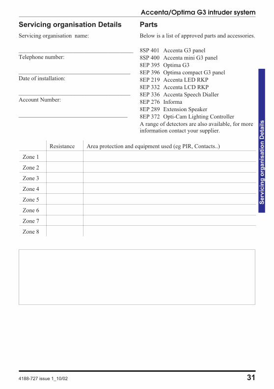
Servicing organisation Details
Servicing organisation name:
_______________________________________
Telephone number:
______________________________________
Date of installation:
______________________________________
Account Number:
_____________________________________
Parts
Below is a list of approved parts and accessories.
8SP 401 Accenta G3 panel
8SP 400 Accenta mini G3 panel
8EP 395 Optima G3
8EP 396 Optima compact G3 panel
8EP 219 Accenta LED RKP
8EP 332 Accenta LCD RKP
8EP 336 Accenta Speech Dialler
8EP 276 Informa
8EP 289 Extension Speaker
8EP 372 Opti-Cam Lighting Controller
A range of detectors are also available, for moreinformation contact your supplier.
Accenta/Optima G3 intruder system
4188-727 issue 1_10/02 31
Serv
icin
go
rgan
isati
on
Deta
ils
Resistance Area protection and equipment used (eg PIR, Contacts..)
Zone 1
Zone 2
Zone 3
Zone 4
Zone 5
Zone 6
Zone 7
Zone 8
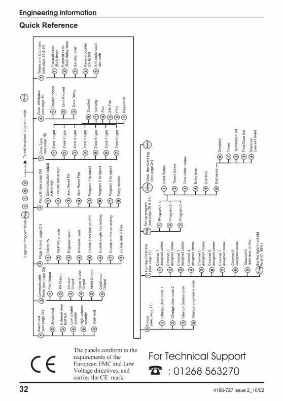
Quick Reference
32 4188-727 issue 2_10/02
Engineering information
Re
se
tS
etup
pro
gra
m(s
ee
page
20
&21)
Pro
gra
m1
2 31
Pro
gra
m2
Pro
gra
m3
Used
Zones
Tim
ed
Zones
Tim
ein
hib
itzones
Exit
tim
e
Exit
mode
5 62 3 41
Entr
ytim
e
Vie
wth
eeventlo
g(s
ee
page
24)
Com
munic
ato
rTests
(see
page
23)
Fire
Outp
ut
2P
AO
utp
ut
3In
truder
Outp
ut
Open
/Clo
se
Outp
ut
4 5A
bort
Outp
ut
Confirm
ed
Outp
ut
61
2A
larm
test
(see
page
22)
1F
lags
A(s
ee
page
21)
Sile
ntP
A
RK
PP
Aenable
Engin
eer
reset
Anti-c
ode
reset
Enable
Door
bell
on
PT
S5
Enable
sin
gle
key
settin
g6
Enable
str
obe
on
settin
g72 3 41
Enable
Bell
inF
ire
8
3F
lags
B(s
ee
page
24)
Com
munic
ato
routp
ut
active
hig
h
Lin
efa
ilactive
hig
h
User
ResetP
A
User
ResetF
ire
Pro
gra
m1
tore
port
Pro
gra
m2
tore
port
Pro
gra
m3
tore
port
5 6 72 3 41
4Z
one
Attribute
s(s
ee
page
19)
Double
Knock
Om
itP
revent
Zone
Dela
y
2 31
6
Str
obe
test
2
Exte
rnalsiren
Bell
test
3
Low
volu
me
sounder
Hig
hvolu
me
sounder
4 5 6
99
99
En
gin
ee
rP
rog
ram
Mo
de
Pro
gTo
exit
en
gin
ee
rp
rog
ram
mo
de
Re
se
t
Zo
ne
Typ
e(s
ee
pa
ge
18
)
Zo
ne
1ty
pe
Zo
ne
2ty
pe
Zo
ne
4ty
pe
Zo
ne
5ty
pe
Zo
ne
6ty
pe
Zo
ne
7ty
pe
Zo
ne
8ty
pe
5 6 72 3 41
5
Dis
ab
led
Se
cu
rity
Fire
24
hF
ire
PT
S
Ke
ysw
itch
4 51 2 30
Entr
ydevia
te8
Co
de
s(s
ee
pa
ge
17
)
Ch
an
ge
Use
rco
de
1
Ch
an
ge
Use
rco
de
2
Ch
an
ge
Du
ress
co
de
Ch
an
ge
En
gin
ee
r’s
co
de
2 3 91
8
An
ti-c
od
ere
se
tsite
co
de
Tim
ers
an
dC
ou
nte
rs(s
ee
pa
ge
25
&2
6)
Exte
rna
lsire
n(B
ell)
tim
er
Exte
rna
lsire
n(B
ell)
de
lay
tim
er
Se
rvic
etim
er
Re
-arm
co
un
ter
(00
to9
9)
2 3 41 5
7
Lig
hting
Contr
olle
r(s
ee
page
27)
Channel1
assig
ned
zones
5 6 72 3 41
Channel2
assig
ned
zones
Channel3
assig
ned
zones
Channel4
assig
ned
zones
Channel5
assig
ned
zones
Channel6
assig
ned
zones
Channel7
assig
ned
zones
Channel9
Hold
tim
e(0
-99s)
8
Pro
gS
etth
elig
htth
reshold
level(0
-99%
)
9
9
Dis
ab
led
Te
rmin
ate
dse
t
Fin
alD
oo
rS
et
Sile
nt
se
t(u
se
exit
tim
e)
2 3 40
Tim
ed
1
Channel8
assig
ned
zones
Pro
gC
him
e
Walk
test
The panels conform to therequirements of theEuropean EMC and LowVoltage directives, andcarries the CE mark.
For Technical Support
� : 01268 563270
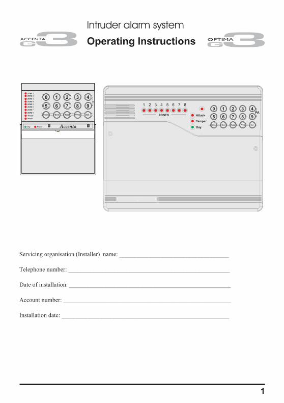
Intruder alarm system
Operating Instructions
Servicing organisation details
Servicing organisation (Installer) name: ____________________________________
Telephone number: _____________________________________________________
Date of installation: _____________________________________________________
Account number: _______________________________________________________
Installation date: _______________________________________________________
1
0 1 2 3
5 6 7 8
Chime Omit Reset
4
9
SetProg
ZONE 1
ZONE 2
ZONE 3
ZONE 4
ZONE 5
ZONE 6
ZONE 7
ZONE 8
Tamper
Attack
Day Power
PA
Accenta
ZONES
Accenta�� mini
0 1 2 3
5 6 7 8
Chime Omit Reset
4
9
SetProg
PAAttack
Tamper
Day
1 2 3 4 5 6 7 8
System installation
This booklet tells you how to operate yourintruder alarm system. To simplify this bookletwe have assumed that the alarm system has beeninstalled by a professional intruder alarm systeminstaller (the installer), and that the system isoperated in a “typical” way. Aspects of yoursystem that are not “typical” will be describedby your installer.
Note: If you have any questions aboutyour intruder system, then consultyour installer, see contact details onthe front page.
Codes
To operate the alarm system you will need to usea code. A code is 4 digits long, and can be anynumber from 0000 to 9999. By default the code
is but you should changethis as soon as possible.
Alarm System Operation
This booklet describes two versions of the alarmsystem. The Optima version has the keypad andindicators on the main control panel. TheAccenta version has the keypad and indicatorson a small remote keypad. You operate the alarmsystem by pressing buttons on the keypad andviewing the indicators. Both alarm systems workthe same way. Both Accenta and Optima
systems can be fitted with an optional remotekeypad.
Personal Attack
If you are under threat, or are being attacked,you can activate the alarm by pressing the 4 and9 keys at the same time on any keypad. Thealarm system will produce a loud alarm sound,and the external siren will be turned on.
Fire Zones
One or more Zones on your alarm system mayhave a Fire or Smoke detector connected to it. Inthe event of a fire the alarm system will producea distinctive two-tone fire alarm sound, and theoutside siren will pulse 2 seconds on, 2 secondsoff. You should leave the premises immediately,and only re-enter when it is safe to do so. Thealarm can be silenced by entering your code.
Power Indicator
The Power indicator on the control panel orkeypad will light whenever the mains powersupply is present. If mains power fails then thePower indicator will go out, but the system willrun from its backup battery for several hours. Ifthe Power indicator goes out when mains poweris present then a fault may have developed onyour system and you should contact yourinstaller.
Warning beeps
Your system may produce warning beeps toinform you of a potential problem. A single beepevery 10 minutes tells you that the system needsto be serviced. You should call your installer toarrange a service visit. The system will continueto operate correctly in all respects.
A double beep every 10 minutes tells you thatthe telephone line that the alarm system uses isnot available or has failed. This may be due tosomeone using a telephone on the same line. Ifthis problem persists you should contact yourinstaller to rectify the problem. Your alarmsystem will continue to operate, but it cannotsend alarm messages via the telephone line.
Signalling Device
Your alarm system may have been fitted with asignalling device. This device uses the telephoneline to send an alarm message to an AlarmReceiving Centre in the event of an alarm. Theoperator at the ARC may request the police toattend your premises.
2
Operating instructions
0 1 2 3
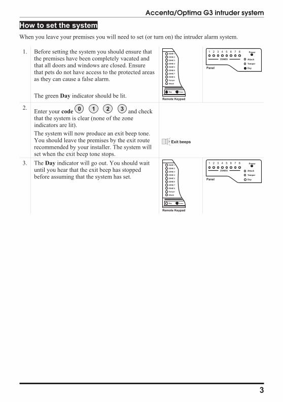
How to set the system
When you leave your premises you will need to set (or turn on) the intruder alarm system.
1. Before setting the system you should ensure thatthe premises have been completely vacated andthat all doors and windows are closed. Ensurethat pets do not have access to the protected areasas they can cause a false alarm.
The green Day indicator should be lit.
2.Enter your code and checkthat the system is clear (none of the zoneindicators are lit).
The system will now produce an exit beep tone.You should leave the premises by the exit routerecommended by your installer. The system willset when the exit beep tone stops.
3. The Day indicator will go out. You should waituntil you hear that the exit beep has stoppedbefore assuming that the system has set.
3
Accenta/Optima G3 intruder system
ZONE 1
ZONE 2
ZONE 3
ZONE 4
ZONE 5
ZONE 6
ZONE 7
ZONE 8
Tamper
Attack
Day
Remote Keypad
Power
ZONES Attack
Tamper
Day
1 2 3 4 5 6 7 8 Power
Panel
0 1 2 3
Exit beeps
ZONE 1
ZONE 2
ZONE 3
ZONE 4
ZONE 5
ZONE 6
ZONE 7
ZONE 8
Tamper
Attack
Day
Remote Keypad
Power
ZONES Attack
Tamper
Day
1 2 3 4 5 6 7 8 Power
Panel
How to Unset the system
When you enter your premises you will need to unset (or turn off) the system.
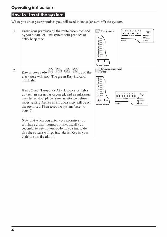
1. Enter your premises by the route recommendedby your installer. The system will produce anentry beep tone.
2.Key in your code , and theentry tone will stop. The green Day indicatorwill light.
If any Zone, Tamper or Attack indicator lightsup then an alarm has occurred, and an intrusionmay have taken place. Seek assistance beforeinvestigating further as intruders may still be onthe premises. Then reset the system (refer topage 7).
Note that when you enter your premises youwill have a short period of time, usually 30seconds, to key in your code. If you fail to dothis the system will go into alarm. Key in yourcode to stop the alarm.
4
Operating instructions
Entry beeps
ZONE 1
ZONE 2
ZONE 3
ZONE 4
ZONE 5
ZONE 6
ZONE 7
ZONE 8
Tamper
Attack
Day
Remote Keypad
Power
ZONES Attack
Tamper
Day
1 2 3 4 5 6 7 8 Power
Panel
0 1 2 3Acknowledgementbeep
ZONE 1
ZONE 2
ZONE 3
ZONE 4
ZONE 5
ZONE 6
ZONE 7
ZONE 8
Tamper
Attack
Day
Remote Keypad
Power
ZONES Attack
Tamper
Day
1 2 3 4 5 6 7 8 Power
Panel
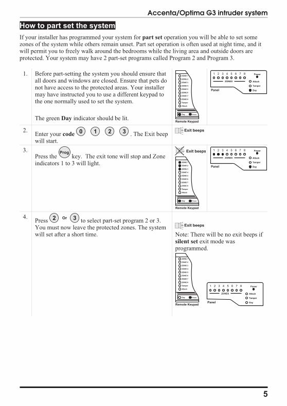
How to part set the system
If your installer has programmed your system for part set operation you will be able to set somezones of the system while others remain unset. Part set operation is often used at night time, and itwill permit you to freely walk around the bedrooms while the living area and outside doors areprotected. Your system may have 2 part-set programs called Program 2 and Program 3.
1. Before part-setting the system you should ensure thatall doors and windows are closed. Ensure that pets donot have access to the protected areas. Your installermay have instructed you to use a different keypad tothe one normally used to set the system.
The green Day indicator should be lit.
2.Enter your code . The Exit beepwill start.
3.Press the key. The exit tone will stop and Zoneindicators 1 to 3 will light.
4.Press to select part-set program 2 or 3.You must now leave the protected zones. The systemwill set after a short time. Note: There will be no exit beeps if
silent set exit mode wasprogrammed.
5
Accenta/Optima G3 intruder system
ZONE 1
ZONE 2
ZONE 3
ZONE 4
ZONE 5
ZONE 6
ZONE 7
ZONE 8
Tamper
Attack
Day
Remote Keypad
Power
ZONES Attack
Tamper
Day
1 2 3 4 5 6 7 8 Power
Panel
0 1 2 3 Exit beeps
Prog Exit beeps
ZONE 1
ZONE 2
ZONE 3
ZONE 4
ZONE 5
ZONE 6
ZONE 7
ZONE 8
Tamper
Attack
Day
Remote Keypad
Power
ZONES Attack
Tamper
Day
1 2 3 4 5 6 7 8 Power
Panel
32 Or
Exit beeps
ZONE 1
ZONE 2
ZONE 3
ZONE 4
ZONE 5
ZONE 6
ZONE 7
ZONE 8
Tamper
Attack
Day
Remote Keypad
Power
ZONES Attack
Tamper
Day
1 2 3 4 5 6 7 8 Power
Panel
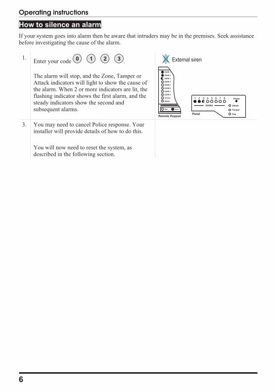
How to silence an alarm
If your system goes into alarm then be aware that intruders may be in the premises. Seek assistancebefore investigating the cause of the alarm.
1.Enter your code .
The alarm will stop, and the Zone, Tamper orAttack indicators will light to show the cause ofthe alarm. When 2 or more indicators are lit, theflashing indicator shows the first alarm, and thesteady indicators show the second andsubsequent alarms.
3. You may need to cancel Police response. Yourinstaller will provide details of how to do this.
You will now need to reset the system, asdescribed in the following section.
6
Operating instructions
0 1 2 3 External siren
ZONE 1
ZONE 2
ZONE 3
ZONE 4
ZONE 5
ZONE 6
ZONE 7
ZONE 8
Tamper
Attack
Day
Remote Keypad
Power
ZONES Attack
Tamper
Day
1 2 3 4 5 6 7 8 Power
Panel
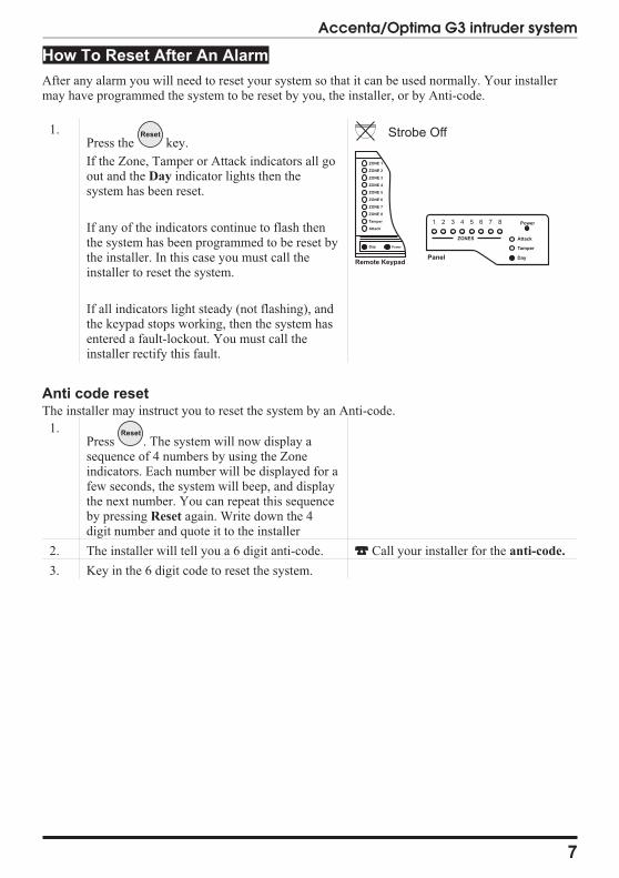
How To Reset After An Alarm
After any alarm you will need to reset your system so that it can be used normally. Your installermay have programmed the system to be reset by you, the installer, or by Anti-code.
1.Press the key.
If the Zone, Tamper or Attack indicators all goout and the Day indicator lights then thesystem has been reset.
If any of the indicators continue to flash thenthe system has been programmed to be reset bythe installer. In this case you must call theinstaller to reset the system.
If all indicators light steady (not flashing), andthe keypad stops working, then the system hasentered a fault-lockout. You must call theinstaller rectify this fault.
Anti code resetThe installer may instruct you to reset the system by an Anti-code.
1.Press . The system will now display asequence of 4 numbers by using the Zoneindicators. Each number will be displayed for afew seconds, the system will beep, and displaythe next number. You can repeat this sequenceby pressing Reset again. Write down the 4digit number and quote it to the installer
2. The installer will tell you a 6 digit anti-code. Call your installer for the anti-code.
3. Key in the 6 digit code to reset the system.
7
Accenta/Optima G3 intruder system
Reset Strobe Off
ZONE 1
ZONE 2
ZONE 3
ZONE 4
ZONE 5
ZONE 6
ZONE 7
ZONE 8
Tamper
Attack
Day
Remote Keypad
Power
ZONES Attack
Tamper
Day
1 2 3 4 5 6 7 8 Power
Panel
Reset
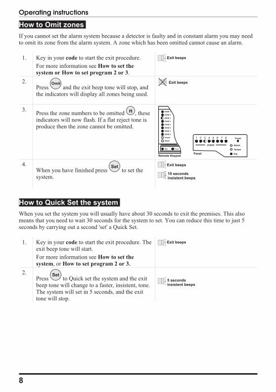
How to Omit zones
If you cannot set the alarm system because a detector is faulty and in constant alarm you may needto omit its zone from the alarm system. A zone which has been omitted cannot cause an alarm.
1. Key in your code to start the exit procedure.
For more information see How to set the
system or How to set program 2 or 3.
2.Press and the exit beep tone will stop, andthe indicators will display all zones being used.
3.Press the zone numbers to be omitted , theseindicators will now flash. If a flat reject tone isproduce then the zone cannot be omitted.
4.When you have finished press to set thesystem.
How to Quick Set the system
When you set the system you will usually have about 30 seconds to exit the premises. This alsomeans that you need to wait 30 seconds for the system to set. You can reduce this time to just 5seconds by carrying out a second 'set' a Quick Set.
1. Key in your code to start the exit procedure. Theexit beep tone will start.
For more information see How to set the
system, or How to set program 2 or 3.
2.Press to Quick set the system and the exitbeep tone will change to a faster, insistent, tone.The system will set in 5 seconds, and the exittone will stop.
8
Operating instructions
Exit beeps
Omit Exit beeps
n ZONE 1
ZONE 2
ZONE 3
ZONE 4
ZONE 5
ZONE 6
ZONE 7
ZONE 8
Tamper
Attack
Day
Remote Keypad
Power
ZONES Attack
Tamper
Day
1 2 3 4 5 6 7 8 Power
Panel
Set Exit beeps
10 secondsinsistent beeps
Exit beeps
Set5 secondsinsistent beeps
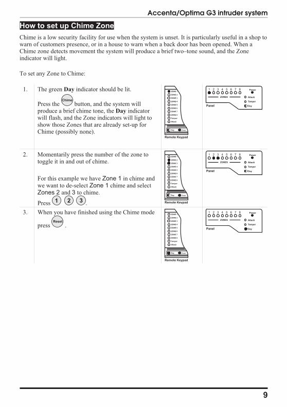
How to set up Chime Zone
Chime is a low security facility for use when the system is unset. It is particularly useful in a shop towarn of customers presence, or in a house to warn when a back door has been opened. When aChime zone detects movement the system will produce a brief two–tone sound, and the Zoneindicator will light.
To set any Zone to Chime:
1. The green Day indicator should be lit.
Press the button, and the system willproduce a brief chime tone, the Day indicatorwill flash, and the Zone indicators will light toshow those Zones that are already set-up forChime (possibly none).
2. Momentarily press the number of the zone totoggle it in and out of chime.
For this example we have Zone 1 in chime andwe want to de-select Zone 1 chime and selectZones 2 and 3 to chime.
Press .
3. When you have finished using the Chime mode
press .
9
Accenta/Optima G3 intruder system
Chime
ZONE 1
ZONE 2
ZONE 3
ZONE 4
ZONE 5
ZONE 6
ZONE 7
ZONE 8
Tamper
Attack
Day
Remote Keypad
Power
ZONES Attack
Tamper
Day
1 2 3 4 5 6 7 8 Power
Panel
321
ZONE 1
ZONE 2
ZONE 3
ZONE 4
ZONE 5
ZONE 6
ZONE 7
ZONE 8
Tamper
Attack
Day
Remote Keypad
Power
ZONES Attack
Tamper
Day
1 2 3 4 5 6 7 8 Power
Panel
Reset
ZONE 1
ZONE 2
ZONE 3
ZONE 4
ZONE 5
ZONE 6
ZONE 7
ZONE 8
Tamper
Attack
Day
Remote Keypad
Power
ZONES Attack
Tamper
Day
1 2 3 4 5 6 7 8 Power
Panel
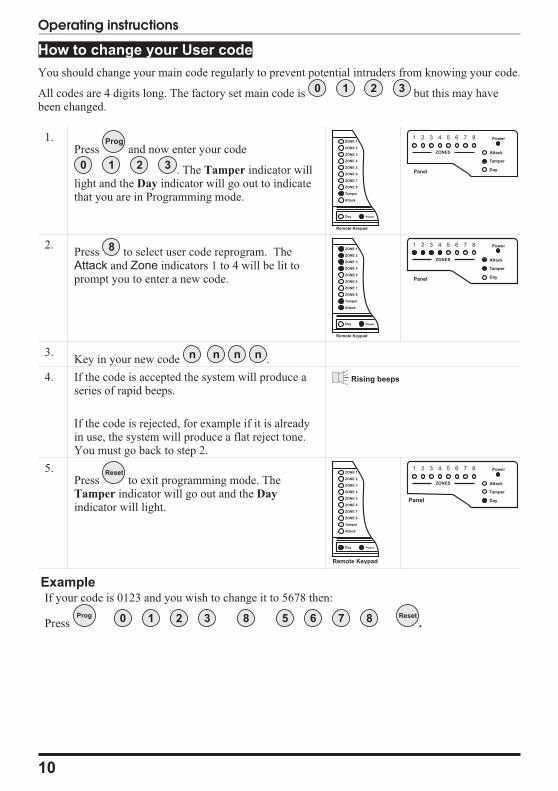
How to change your User code
You should change your main code regularly to prevent potential intruders from knowing your code.
All codes are 4 digits long. The factory set main code is but this may havebeen changed.
1.Press and now enter your code
. The Tamper indicator willlight and the Day indicator will go out to indicatethat you are in Programming mode.
2.Press to select user code reprogram. TheAttack and Zone indicators 1 to 4 will be lit toprompt you to enter a new code.
3.Key in your new code .
4. If the code is accepted the system will produce aseries of rapid beeps.
If the code is rejected, for example if it is alreadyin use, the system will produce a flat reject tone.You must go back to step 2.
5.Press to exit programming mode. TheTamper indicator will go out and the Day
indicator will light.
ExampleIf your code is 0123 and you wish to change it to 5678 then:
Press .
10
Operating instructions
0 1 2 3
Prog
0 1 2 3
ZONE 1
ZONE 2
ZONE 3
ZONE 4
ZONE 5
ZONE 6
ZONE 7
ZONE 8
Tamper
Attack
Day
Remote Keypad
Power
ZONES Attack
Tamper
Day
1 2 3 4 5 6 7 8 Power
Panel
8 ZONE 1
ZONE 2
ZONE 3
ZONE 4
ZONE 5
ZONE 6
ZONE 7
ZONE 8
Tamper
Attack
Day
Remote Keypad
Power
ZONES Attack
Tamper
Day
1 2 3 4 5 6 7 8 Power
Panel
n n n n
Rising beeps
Reset ZONE 1
ZONE 2
ZONE 3
ZONE 4
ZONE 5
ZONE 6
ZONE 7
ZONE 8
Tamper
Attack
Day
Remote Keypad
Power
ZONES Attack
Tamper
Day
1 2 3 4 5 6 7 8 Power
Panel
Prog 0 1 2 3 8 5 6 7 8 Reset
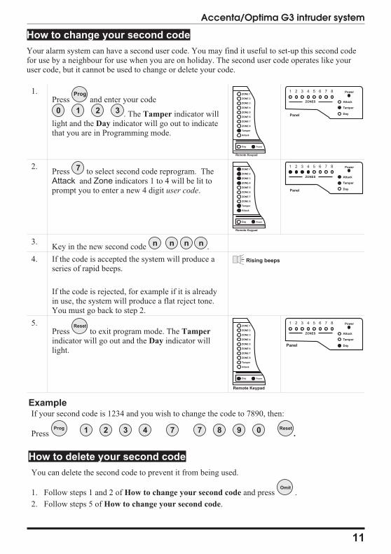
How to change your second code
Your alarm system can have a second user code. You may find it useful to set-up this second codefor use by a neighbour for use when you are on holiday. The second user code operates like youruser code, but it cannot be used to change or delete your code.
1.Press and enter your code
. The Tamper indicator willlight and the Day indicator will go out to indicatethat you are in Programming mode.
2.Press to select second code reprogram. TheAttack and Zone indicators 1 to 4 will be lit toprompt you to enter a new 4 digit user code.
3.Key in the new second code .
4. If the code is accepted the system will produce aseries of rapid beeps.
If the code is rejected, for example if it is alreadyin use, the system will produce a flat reject tone.You must go back to step 2.
5.Press to exit program mode. The Tamper
indicator will go out and the Day indicator willlight.
ExampleIf your second code is 1234 and you wish to change the code to 7890, then:
Press .
How to delete your second code
You can delete the second code to prevent it from being used.
1. Follow steps 1 and 2 of How to change your second code and press .
2. Follow steps 5 of How to change your second code.
11
Accenta/Optima G3 intruder system
Prog
0 1 2 3
ZONE 1
ZONE 2
ZONE 3
ZONE 4
ZONE 5
ZONE 6
ZONE 7
ZONE 8
Tamper
Attack
Day
Remote Keypad
Power
ZONES Attack
Tamper
Day
1 2 3 4 5 6 7 8 Power
Panel
7 ZONE 1
ZONE 2
ZONE 3
ZONE 4
ZONE 5
ZONE 6
ZONE 7
ZONE 8
Tamper
Attack
Day
Remote Keypad
Power
ZONES Attack
Tamper
Day
1 2 3 4 5 6 7 8 Power
Panel
n n n n
Rising beeps
Reset ZONE 1
ZONE 2
ZONE 3
ZONE 4
ZONE 5
ZONE 6
ZONE 7
ZONE 8
Tamper
Attack
Day
Remote Keypad
Power
ZONES Attack
Tamper
Day
1 2 3 4 5 6 7 8 Power
Panel
Prog 1 2 3 4 7 7 8 9 0 Reset
Omit
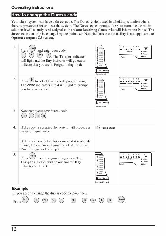
How to change the Duress code
Your alarm system can have a duress code. The Duress code is used in a hold-up situation wherethere is pressure to set or unset the system. The Duress code operates like your normal code but inaddition it will silently send a signal to the Alarm Receiving Centre who will inform the Police. Theduress code can only be changed by the main user. Note the Duress code facility is not applicable toOptima compact G3 system.
1.Press and enter your code
. The Tamper indicatorwill light and the Day indicator will go out toindicate that you are in Programming mode.
2.Press to select Duress code programming.The Zone indicators 1 to 4 will light to promptyou for a new code.
3. Now enter your new duress code
.
4. If the code is accepted the system will produce aseries of rapid beeps.
If the code is rejected, for example if it is alreadyin use, the system will produce a flat reject tone.You must go back to step 2.
5.Press to exit programming mode. TheTamper indicator will go out and the Day
indicator will light.
ExampleIf you need to change the duress code to 6543, then:
Press .
12
Operating instructions
Prog
0 1 2 3
ZONE 1
ZONE 2
ZONE 3
ZONE 4
ZONE 5
ZONE 6
ZONE 7
ZONE 8
Tamper
Attack
Day
Remote Keypad
Power
ZONES Attack
Tamper
Day
1 2 3 4 5 6 7 8 Power
Panel
9 ZONE 1
ZONE 2
ZONE 3
ZONE 4
ZONE 5
ZONE 6
ZONE 7
ZONE 8
Tamper
Attack
Day
Remote Keypad
Power
ZONES Attack
Tamper
Day
1 2 3 4 5 6 7 8 Power
Panel
n n n n
Rising beeps
Reset ZONE 1
ZONE 2
ZONE 3
ZONE 4
ZONE 5
ZONE 6
ZONE 7
ZONE 8
Tamper
Attack
Day
Remote Keypad
Power
ZONES Attack
Tamper
Day
1 2 3 4 5 6 7 8 Power
Panel
Prog 0 1 2 3 9 6 5 4 3 Reset
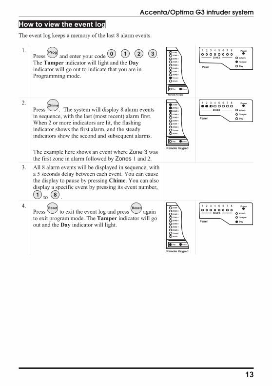
How to view the event log
The event log keeps a memory of the last 8 alarm events.
1.Press and enter your code .The Tamper indicator will light and the Day
indicator will go out to indicate that you are inProgramming mode.
2.
Press . The system will display 8 alarm eventsin sequence, with the last (most recent) alarm first.When 2 or more indicators are lit, the flashingindicator shows the first alarm, and the steadyindicators show the second and subsequent alarms.
The example here shows an event where Zone 3 wasthe first zone in alarm followed by Zones 1 and 2.
3. All 8 alarm events will be displayed in sequence, witha 5 seconds delay between each event. You can causethe display to pause by pressing Chime. You can alsodisplay a specific event by pressing its event number,
to .
4.Press to exit the event log and press againto exit program mode. The Tamper indicator will goout and the Day indicator will light.
13
Accenta/Optima G3 intruder system
Prog 0 1 2 3ZONE 1
ZONE 2
ZONE 3
ZONE 4
ZONE 5
ZONE 6
ZONE 7
ZONE 8
Tamper
Attack
Day
Remote Keypad
Power
ZONES Attack
Tamper
Day
1 2 3 4 5 6 7 8 Power
Panel
ChimeChime ZONE 1
ZONE 2
ZONE 3
ZONE 4
ZONE 5
ZONE 6
ZONE 7
ZONE 8
Tamper
Attack
Day
Remote Keypad
Power
ZONES Attack
Tamper
Day
1 2 3 4 5 6 7 8 Power
Panel
1 8
Reset Reset ZONE 1
ZONE 2
ZONE 3
ZONE 4
ZONE 5
ZONE 6
ZONE 7
ZONE 8
Tamper
Attack
Day
Remote Keypad
Power
ZONES Attack
Tamper
Day
1 2 3 4 5 6 7 8 Power
Panel
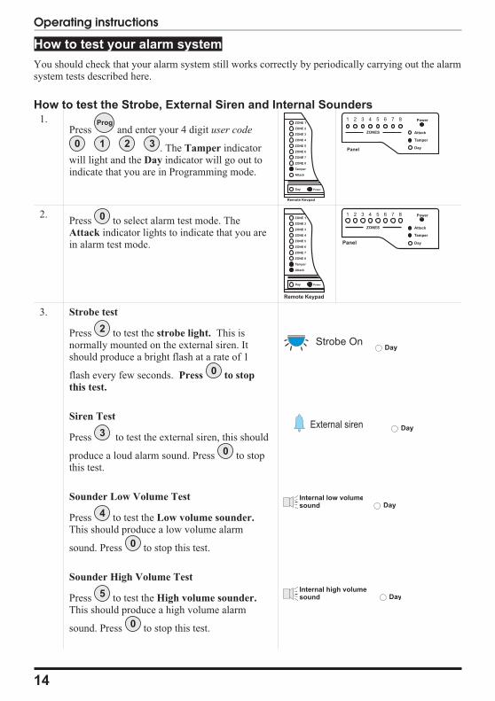
How to test your alarm system
You should check that your alarm system still works correctly by periodically carrying out the alarmsystem tests described here.
How to test the Strobe, External Siren and Internal Sounders1.
Press and enter your 4 digit user code
. The Tamper indicatorwill light and the Day indicator will go out toindicate that you are in Programming mode.
2.Press to select alarm test mode. TheAttack indicator lights to indicate that you arein alarm test mode.
3. Strobe test
Press to test the strobe light. This isnormally mounted on the external siren. Itshould produce a bright flash at a rate of 1
flash every few seconds. Press to stop
this test.
Siren Test
Press to test the external siren, this should
produce a loud alarm sound. Press to stopthis test.
Sounder Low Volume Test
Press to test the Low volume sounder.
This should produce a low volume alarm
sound. Press to stop this test.
Sounder High Volume Test
Press to test the High volume sounder.
This should produce a high volume alarm
sound. Press to stop this test.
14
Operating instructions
Prog
0 1 2 3
ZONE 1
ZONE 2
ZONE 3
ZONE 4
ZONE 5
ZONE 6
ZONE 7
ZONE 8
Tamper
Attack
Day
Remote Keypad
Power
ZONES Attack
Tamper
Day
1 2 3 4 5 6 7 8 Power
Panel
0 ZONE 1
ZONE 2
ZONE 3
ZONE 4
ZONE 5
ZONE 6
ZONE 7
ZONE 8
Tamper
Attack
Day
Remote Keypad
Power
ZONES Attack
Tamper
Day
1 2 3 4 5 6 7 8 Power
Panel
2
0
3
0
4
0
5
0
Strobe OnDay
External siren Day
Internal low volumesound Day
Internal high volumesound Day

Walktest
Press to carry out a walktest. Walk aroundyour property, and in turn cause each of thedetectors to go into alarm. Also, open and closeall door and windows that are protected by thesystem. For each detector (including door orwindow sensor) that is activated the systemwill produce a series of beeps, and theassociated zone indicator will light.
Press to stop this test.
IMPORTANT: Do not test any“Personal Attack” buttons during thewalktest, since these are still active andwill cause a full alarm.
If any of the alarm tests fail, or you are unsureof the correct procedure, contact your installer.
4.Press to exit Alarm test and pressagain to exit program mode. The Tamper
indicator will go out and the Day indicator willlight.
15
Accenta/Optima G3 intruder system
0
Reset Reset ZONE 1
ZONE 2
ZONE 3
ZONE 4
ZONE 5
ZONE 6
ZONE 7
ZONE 8
Tamper
Attack
Day
Remote Keypad
Power
ZONES Attack
Tamper
Day
1 2 3 4 5 6 7 8 Power
Panel
6
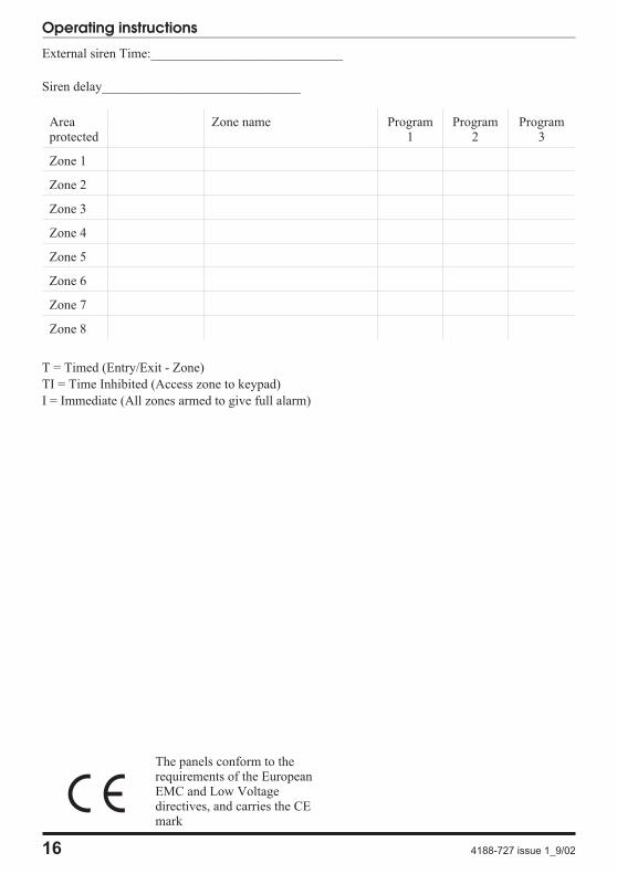
External siren Time:_____________________________
Siren delay______________________________
Areaprotected
Zone name Program1
Program2
Program3
Zone 1
Zone 2
Zone 3
Zone 4
Zone 5
Zone 6
Zone 7
Zone 8
T = Timed (Entry/Exit - Zone)
TI = Time Inhibited (Access zone to keypad)
I = Immediate (All zones armed to give full alarm)
16 4188-727 issue 1_9/02
Operating instructions
The panels conform to therequirements of the EuropeanEMC and Low Voltagedirectives, and carries the CEmark