final presentation of ddk
TRANSCRIPT
Summer training presentation on
1
Training at DDK,
VARANASI
Presented by Krishna Kant UpadhyayECE (1003331824)
Contents• Introduction• TV Studio• Vision mixer• Audio & video chain• MSR • Earth station• OB VAN & DSNG
2
Introductionprocess of sending information to a distant place is called Broadcasting.
• Means of Broadcasting in India: 1. Terrestrial 2. Satellite 3. Internet
• Both AIR & DD make use of both Terrestrial & satellite. 3
Introduction contd…• Broadcasting started in India in the year
1923.• AIR was formed in the year 1936.• In 1947, AIR was covering 2.5% & about
11% of land & population respectively.• 1st T.V Station was established in Delhi in
1959• T.V was separated from AIR in 1976• DD has 1500 Transmitters and 70
Production centers across the Country.4
TV studio
5
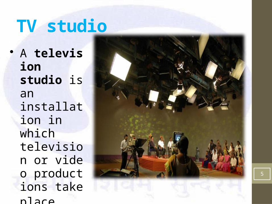
• A television studio is an installation in which television or video productions take place.
Components of TV studio
• Camera• Lighting• Microphones• Vision mixer and Audio consoles• MSR• VTR• Acoustics• Post production and video effects• Supporting services like AC, UPS
6
Vision Mixer
7
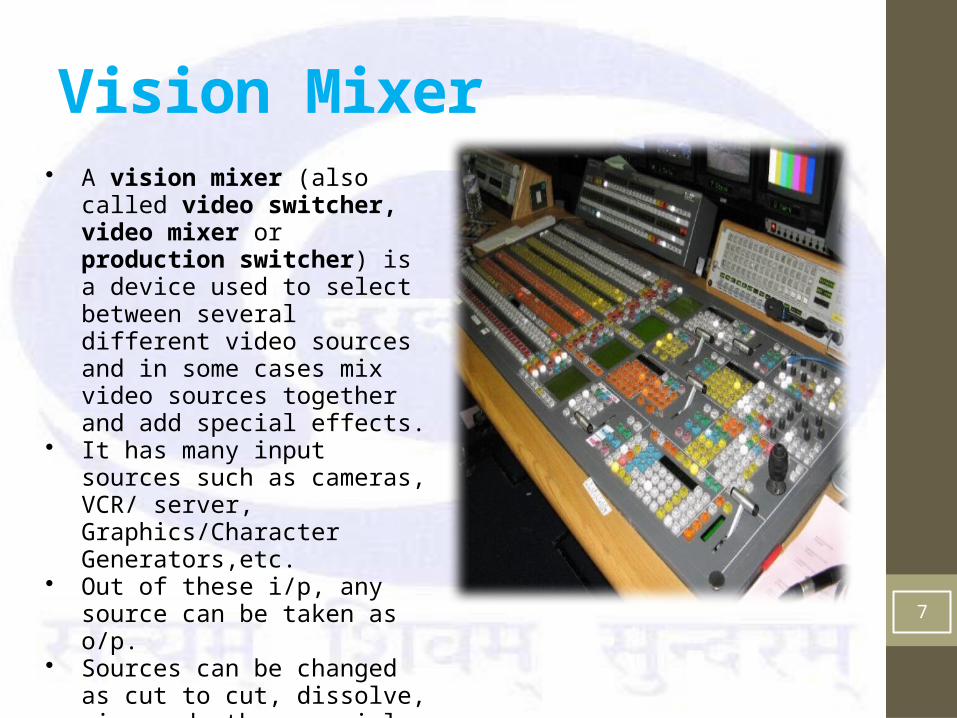
• A vision mixer (also called video switcher, video mixer or production switcher) is a device used to select between several different video sources and in some cases mix video sources together and add special effects.
• It has many input sources such as cameras, VCR/ server, Graphics/Character Generators,etc.
• Out of these i/p, any source can be taken as o/p.
• Sources can be changed as cut to cut, dissolve, wipe and other special effects.
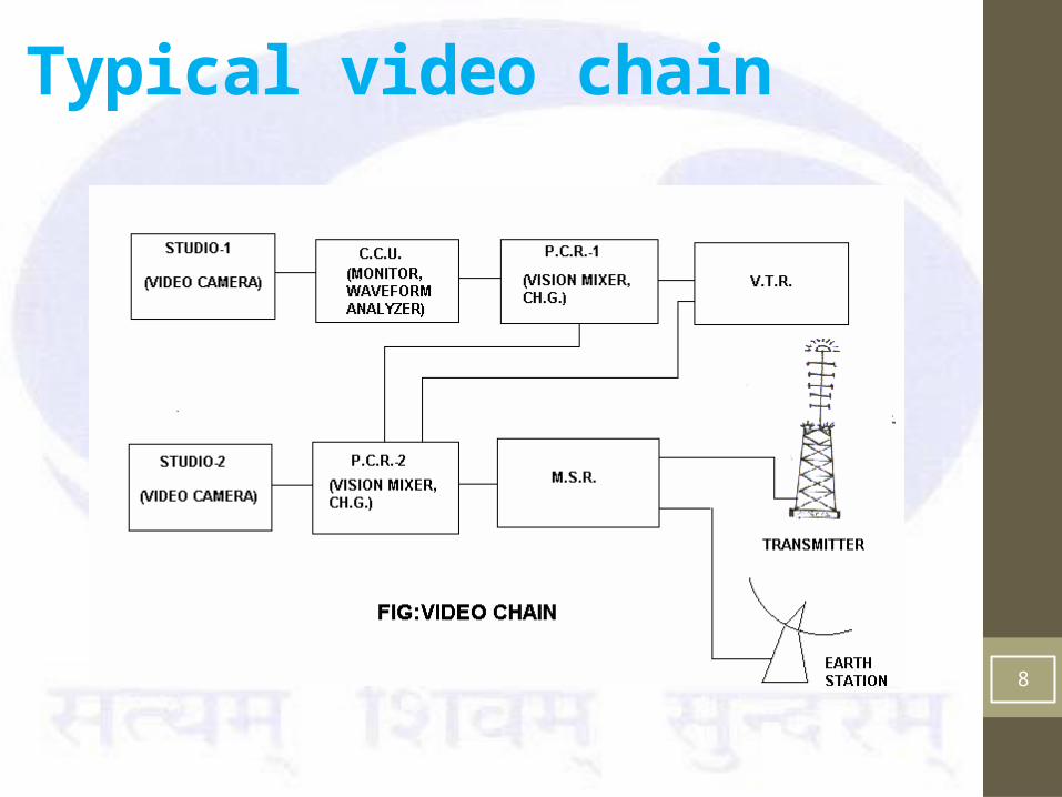
Typical video chain
8
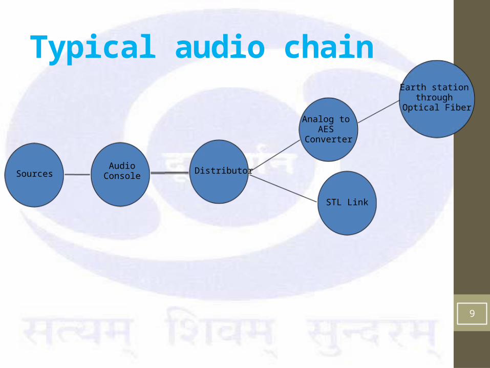
Typical audio chain
9
DistributorAudio Console
Analog to AES
Converter
Earth station through
Optical Fiber
STL Link
Sources
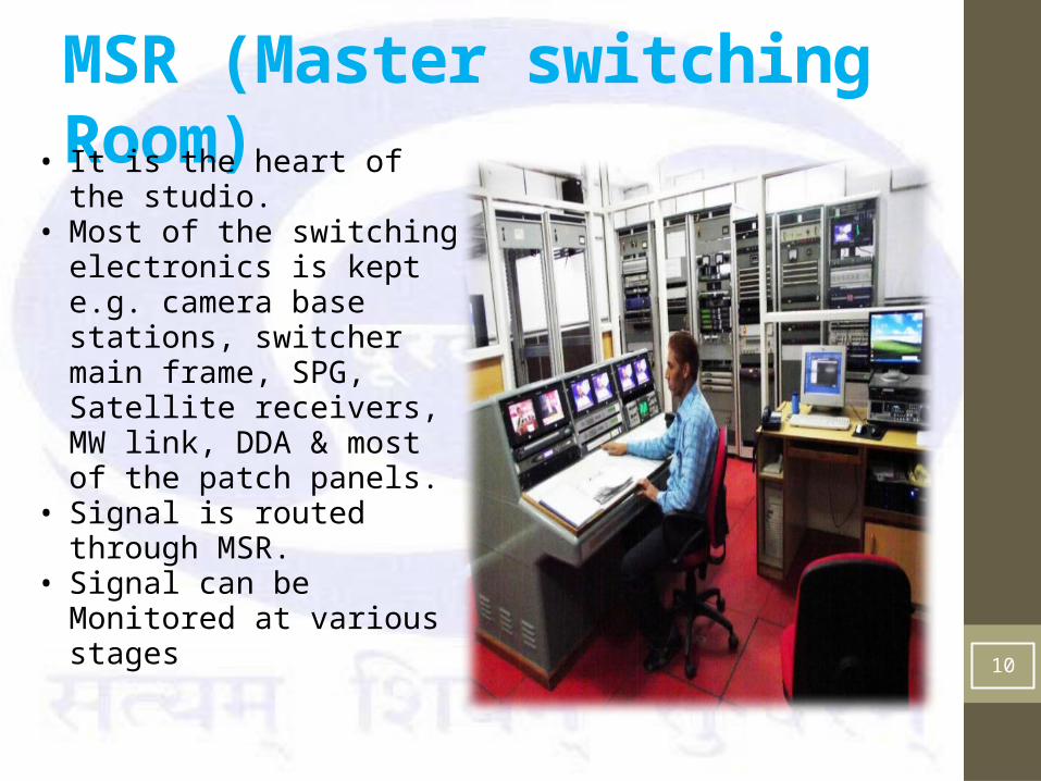
MSR (Master switching Room)• It is the heart of the
studio.• Most of the switching
electronics is kept e.g. camera base stations, switcher main frame, SPG, Satellite receivers, MW link, DDA & most of the patch panels.
• Signal is routed through MSR.
• Signal can be Monitored at various stages
10
Earth station
11
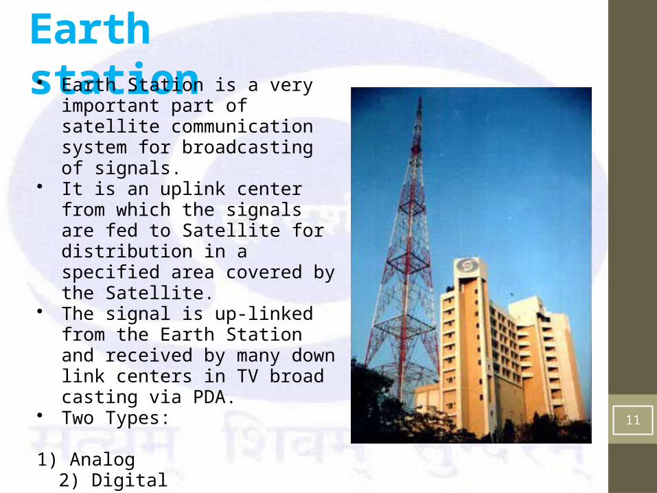
• Earth Station is a very important part of satellite communication system for broadcasting of signals.
• It is an uplink center from which the signals are fed to Satellite for distribution in a specified area covered by the Satellite.
• The signal is up-linked from the Earth Station and received by many down link centers in TV broad casting via PDA.
• Two Types: 1) Analog 2) Digital
• Digital Earth Stations are widely used because of various advantages over analog.
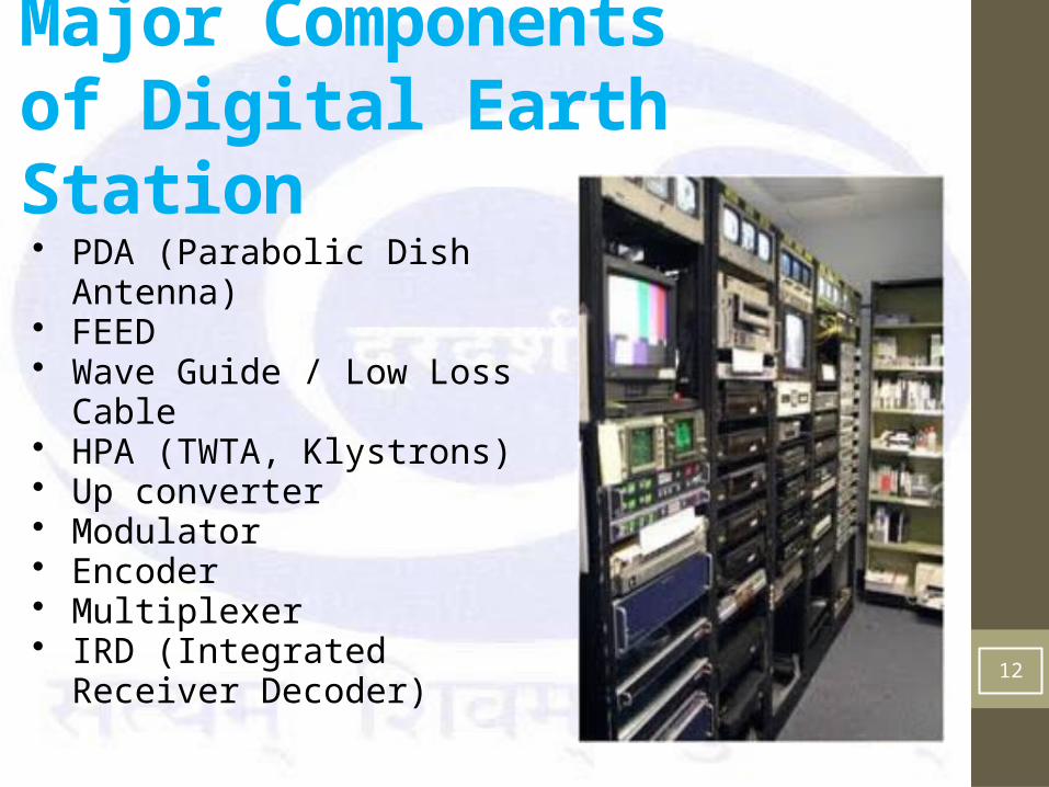
Major Components of Digital Earth Station
12
• PDA (Parabolic Dish Antenna)• FEED• Wave Guide / Low Loss Cable• HPA (TWTA, Klystrons)• Up converter• Modulator• Encoder• Multiplexer• IRD (Integrated Receiver
Decoder)
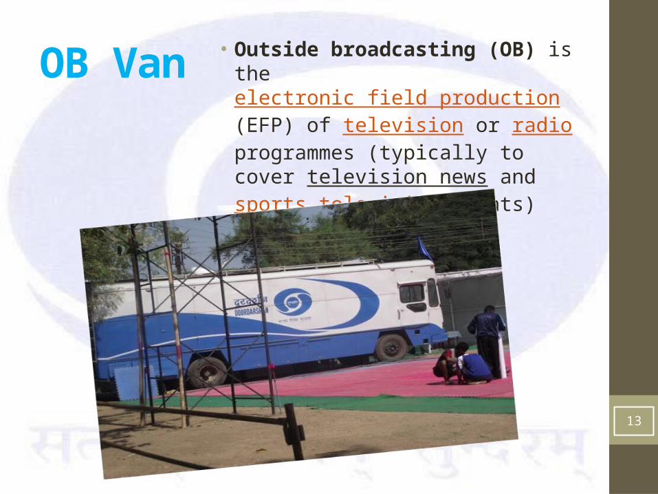
OB Van • Outside broadcasting (OB) is the electronic field production (EFP) of television or radio programmes (typically to cover television news and sports television events) from a mobile remote broadcast television studio.
13
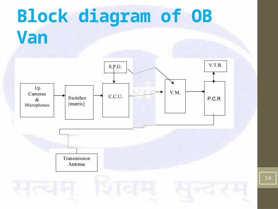
Block diagram of OB Van
14
OB Van• A typical OB Van is usually divided into 4 parts.• The first and largest part is the production area or
sitting area for all directors & producers.• The second part of a van is for the audio engineer.• The 3rd part of the van is video tape• The 4th part is transmission where the signal is
monitored by and engineered for quality control purposes and is transmitted or sent to other trucks.
15
If there is a live program to be telecast following options can be choosed.
Microwave link DSNG (digital satellite news gathering)
Microwave link
16
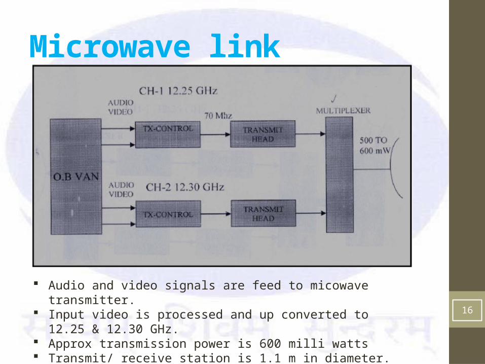
Audio and video signals are feed to micowave transmitter. Input video is processed and up converted to 12.25 & 12.30 GHz. Approx transmission power is 600 milli watts Transmit/ receive station is 1.1 m in diameter.
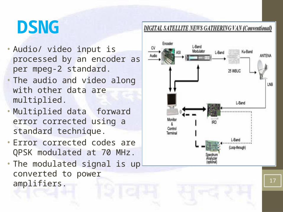
DSNG• Audio/ video input is processed by
an encoder as per mpeg-2 standard.• The audio and video along with
other data are multiplied.• Multiplied data forward error
corrected using a standard technique.
• Error corrected codes are QPSK modulated at 70 MHz.
• The modulated signal is up converted to power amplifiers.
17
Thank you…
18
Any queries ?