final class 2 permit modification request trupact iii...
TRANSCRIPT
Department of Energy Carlsbad Field Office
P. O. Box 3090 Carlsbad, New Mexico 8822 1
January 10, 2011
Mr. James Bearzi. Chief Hazardous Waste Bureau New Mexico Environment Department 2905 Rodeo Park Drive East, Building 1 Santa Fe, New Mexico 87505-6303
Subject: Notification of a Class 2 Permit Modification to Permit Number: NM4890139088-TSDF
Dear Mr. Bearzi:
Enclosed is a Class 2 Permit Modification Request to:
• Add TRUPACT-II I and Standard Large Box 2 • Revise Area of Contact-Handled Bay
We certify under penalty of law that this document and the enclosure were prepared under our direction or supervision in accordance with a system designed to assure that qualified personnel properly gather and evaluate the information sUbmitted. Based on our inquiry of the person or persons who manage the system, or those persons directly responsible for gathering the information , the information submitted is, to the best of our knowledge and belief, true, accurate, and complete. We are aware that there are significant penalties for submitting false information , including the possibility of fine and imprisonment for knowing violations.
If you have any questions regarding this submittal , please contact George T . Basabilvazo , at (575) 234-7488 .
Sincerely,
Edward Ziemianski , Acting Manager Carlsbad Field Office
Enclosure
cc: w/enclosure S. lappe, NMED ' ED C. Walker, Trinity Engineering ED
cc: w/o enclosure J. Kieling, NMED ED *ED denotes electronic distribution
CBFO:OESH:GTB:MAG:11·0701 :UFC 5487.00
M. F. 3harif, General Manager Washington TRU Solutions LLC

Class 2 Permit Modification Request
Add TRUPACT-III and Standard Large Box 2 Revise Area of Contact-Handled Bay
Waste Isolation Pilot Plant
Carlsbad, New Mexico
WIPP HWFP Number - NM4890139088-TSDF
January 2011
i
Table of Contents
Transmittal Letter Table of Contents ......................................................................................................................... i Acronyms and Abbreviations ...................................................................................................... ii Item 1 Overview of the Permit Modification Request ................................................................. 1 Regulatory Crosswalk........................................................................................................ 14 Attachment A Table of Changes ............................................................................................. A-1 Table of Changes ............................................................................................................. A-2 Attachment B Proposed Revised Permit Text ......................................................................... B-1 Proposed Revised Permit Text ......................................................................................... B-2 Attachment C Drum Age Criteria Values for the Standard Large Box 2 (SLB2) Attachment D Supplemental Information Attachment E Proposed Revised Permit Figures
ii
Acronyms and Abbreviations CBFO Carlsbad Field Office CFR Code of Federal Regulations CH contact-handled DAC drum age criteria DOE U.S. Department of Energy DSA Documented Safety Analysis HEPA high efficiency particulate air HWDU Hazardous Waste Disposal Unit NMAC New Mexico Administrative Code NMED New Mexico Environment Department NRC Nuclear Regulatory Commission PAU Parking Area Unit Permit Hazardous Waste Facility Permit PMR Permit Modification Request SLB2 standard large box 2 SWB standard waste box TDOP ten-drum overpack TRU transuranic WHB Waste Handling Building WIPP Waste Isolation Pilot Plant WTS Washington TRU Solutions LLC
1
Overview of the Permit Modification Request This document contains one Class 2 permit modification request (PMR) to the Hazardous Waste Facility Permit (Permit) for the Waste Isolation Pilot Plant (WIPP) facility, Permit Number NM4890139088-TSDF. This PMR is being submitted by the U.S. Department of Energy (DOE), Carlsbad Field Office (CBFO) and Washington TRU Solutions LLC (WTS), collectively referred to as the Permittees, in accordance with the Permit Part 1, Section 1.3.1 (20.4.1.900 New Mexico Administrative Code (NMAC) incorporating Title 40 Code of Federal Regulations (CFR) §270.42(d)). This modification to the Permit is being requested for the following items:
1. Add the TRUPACT-III as a shipping package 2. Add the standard large box 2 (SLB2) as a storage and disposal container 3. Add Room 108 and Airlock 107 as part of the contact-handled (CH) bay 4. Add equipment to the facility to allow for the handling of the TRUPACT-III
and SLB2 This shipping package, container and handling equipment will be used to manage CH transuranic (TRU) mixed waste that is approved for shipment to the WIPP facility for disposal. These changes do not reduce the ability of the Permittees to provide continued protection to human health and the environment. The requested modification to the WIPP facility Permit and related supporting documents are provided in this PMR. The proposed modification to the text of the WIPP Permit has been identified using red text and a double underline for new text and a strikeout font for deleted information. The following information specifically addresses how compliance has been achieved with the WIPP Permit Part 1, Section 1.3.1 for submission of this Class 2 PMR.
2
1. 20.4.1.900 NMAC (incorporating 40 CFR §270.42(b)(1)(i)), requires the
applicant to describe the exact change to be made to the permit conditions and supporting documents referenced by the permit.
This PMR proposes to allow the receipt and management of the TRUPACT-III and SLB2 at the WIPP facility. The SLB2 is necessary for large pieces of radioactively contaminated equipment packaged in containers too large to be shipped in a TRUPACT-II or HalfPACT. The proposed changes are in the following parts and attachments of the Permit:
• Part 1 (adding TRUPACT-III as a contact-handled package). • Part 3 (adding SLB2 as a TRU mixed waste container; adding TRUPACT-III as a
contact-handled package). • Part 4 (adding SLB2 as a TRU mixed waste container). • Attachment A1 (adding SLB2 as an approved container; revising the area of the
CH Bay; describing the method by which CH TRU mixed waste is managed on the surface when it arrives in a TRUPACT-III; adding TRUPACT-III as a contact-handled package; adding new equipment required for the management of TRUPACT-III and SLB2; revise tables and figures to account for TRUPACT-III, SLB2, Airlock 107, and Room 108).
• Attachment A2 (adding SLB2 as an approved container; revise CH TRU mixed waste emplacement process; revise emplacement procedure).
• Attachment A4 (revising WHB traffic flow to include management of TRUPACT-III and SLB2; revise figures to include Airlock 107 and Room 108 and traffic flow for TRUPACT-III and SLB2).
• Attachment B (revising figures to include Airlock 107 and Room 108 in the CH Bay).
• Attachment C1 (adding SLB2 as a TRU mixed waste container, adding drum age criteria (DAC) values for the SLB2 and adding filter hydrogen diffusivity for SLB2).
• Attachment D (adding SLB2 as a TRU mixed waste container; revising the area of the WHB that is included in the CH Bay; describing the method by which CH TRU mixed waste is managed when it arrives in a TRUPACT-III; describing that SLB2 will be decontaminated and not overpacked).
• Attachment E (adding SLB2 as a TRU mixed waste container and include areas of the WHB where TRU mixed waste in SLB2 containers will be in the inspection schedule and procedures and applicable equipment inspections).
• Attachment G3 (revise Table G3-2; add Table G3-2a). • Attachment J (revise area of CH Bay).
The Table of Changes and the redline strikeout in this modification describe each change that is being proposed.

3
2. 20.4.1.900 NMAC (incorporating 40 CFR §270.42(b)(1)(ii)), requires the
applicant to identify that the modification is a Class 2 modification. The proposed modification is classified as a Class 2 permit modification for the reasons indicated below:
“F. Containers, 2. a. Modification of a container unit without increasing the capacity of the unit…” in accordance with 20.4.1.900 NMAC (incorporating 40 CFR §270.42 Appendix I, Item F.2.a).
The following also applies per the addition of DAC values:
“B. General Facility Standards, 1. Changes to waste sampling or analysis methods: d. Other changes…” in accordance with 20.4.1.900 NMAC (incorporating 40 CFR §270.42 Appendix I, Item B.1.d).
3. 20.4.1.900 NMAC (incorporating 40 CFR §270.42(b)(1)(iii)), requires the
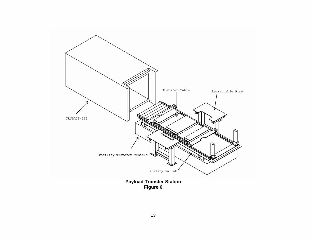
applicant to explain why the modification is needed. This Class 2 permit modification is needed to allow the receipt and management of TRUPACT-III and SLB2. The TRUPACT-III is the shipping container for the SLB2. The SLB2 is a container designed to ship large pieces of equipment (e.g., gloveboxes, motors, pumps) that are radioactively contaminated and for CH TRU waste packaged into boxes too large to be shipped in a TRUPACT-II or HalfPACT. These containers are used by the generator/storage sites for packaging large items, thereby reducing physical, radiological or hazardous material exposures that would result from size reduction activities. “Size reduction activities” is a generic term used to refer to cutting up large radioactively contaminated items so they will fit into smaller waste containers. An additional area within the Waste Handling Building (WHB) is needed for the unloading of the SLB2 from the TRUPACT-III, as described below. The TRUPACT-III is a horizontally loaded CH Package that is needed to ship SLB2 waste containers. The proposed process for receiving loaded CH Packages (TRUPACT-III) into the Parking Area Unit (PAU) is the same as for other CH Packages (TRUPACT-II or HalfPACT) (i.e., security checks, radiological surveys, manifest reviews, and traffic patterns). Therefore, no changes are proposed to the Permit for these receipt processes for the TRUPACT-III. In the PAU, the Permittees are proposing to transfer the TRUPACT-III from a trailer onto a Yard Transfer Vehicle, which will move the TRUPACT-III from the PAU into Room 108. In Room 108, the overpack cover and closure lid for the TRUPACT-III will be supported by an overhead crane while the bolts are removed. The crane will move the overpack cover and closure lid to the storage stands. A Facility Transfer Vehicle with a transfer table with rollers will then be located in the area adjacent to the TRUPACT-III. Rollers in the TRUPACT-III allow the SLB2 to be removed from the TRUPACT-III onto the transfer table. At the Payload Transfer

4
Station the SLB2 is removed and placed on an awaiting Facility Pallet that is staged on a Facility Transfer Vehicle. The Facility Transfer Vehicle with a loaded facility pallet will then be moved to a storage location within the WHB Unit or to the Waste Hoist Conveyance. The facility pallet containing an SLB2 may also be moved using a forklift. At this point, the process for handling the SLB2 is the same as described in the Permit for other CH TRU mixed waste. The information below provides an overview of the equipment necessary to manage SLB2 containers, the areas required in the WHB, and the drum age criteria (DAC) that will be used for the SLB2.
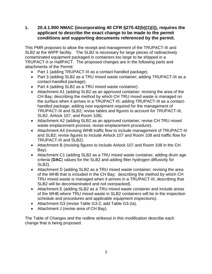
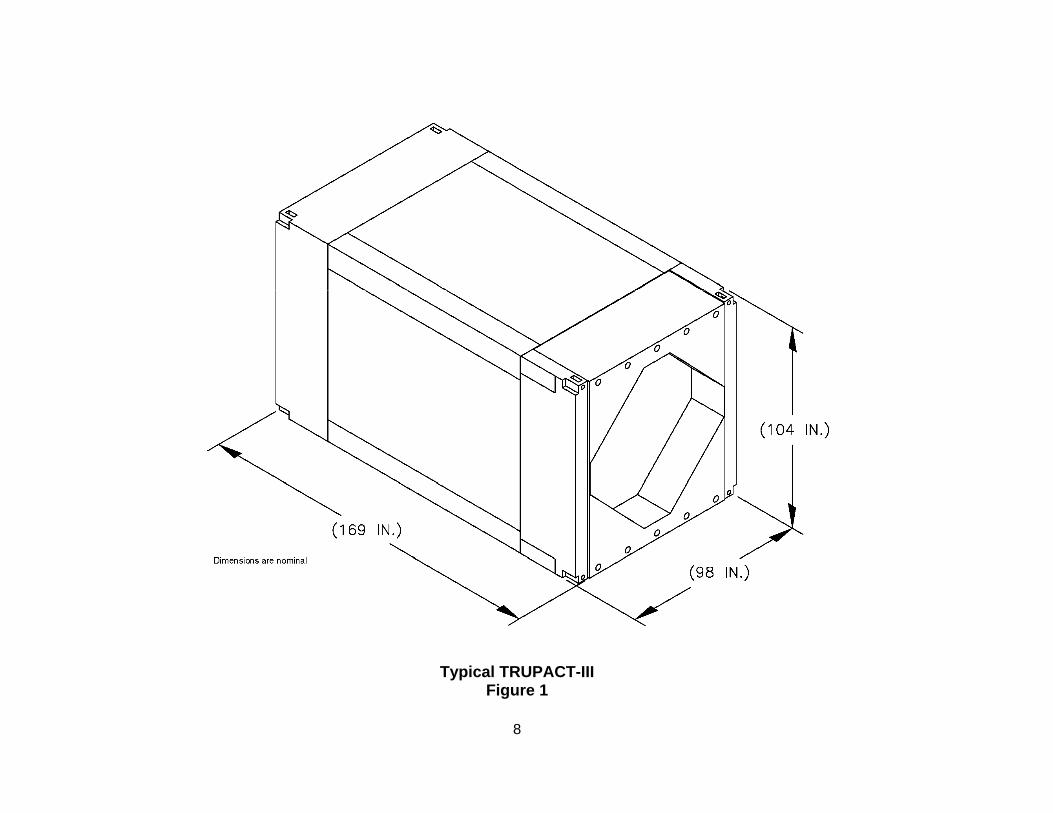
• TRUPACT-III The TRUPACT-III (Figure 1) is a Nuclear Regulatory Commission (NRC) certified Type B package (Attachment D) designed to meet the containment and shielding requirements of 10 CFR 71. The TRUPACT-III is specifically certified to safely transport TRU wastes packaged in an SLB2. The containment boundary and primary structural members of the TRUPACT-III are constructed of stainless steel. The containment boundary structure consists of an inner shell that is backed by a corrugated sheet of stainless steel and an outer structural shell. Completely surrounding the containment boundary structure is a combination of energy absorbing and insulating materials that provide both structural and thermal protection. The TRU mixed waste in this package, unlike the TRUPACT-II or HalfPACT, is horizontally loaded and will be unloaded horizontally as well. The TRUPACT-III has a bolted overpack cover that is secured to the TRUPACT-III container. The nominal dimensions for a TRUPACT-III are 14 feet 1 inch long, 8 feet 2 inches wide and 8 feet 8 inches high (Attachment D). The maximum weight of a loaded TRUPACT-III is 55,116 pounds and the maximum allowable weight of the contents is 11,486 pounds.
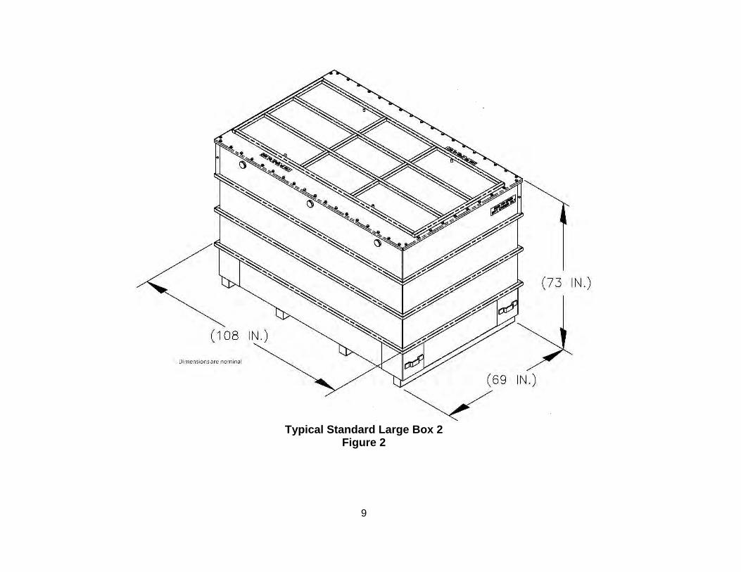
• Standard Large Box 2 (SLB2) The SLB2 (Figure 2) is a steel DOT Type A container used for packaging oversized equipment. This container is designed to accommodate items that exceed the volume capacity of existing payload containers. The SLB2 will not fit inside either the TRUPACT-II or the HalfPACT, therefore the TRUPACT-III was designed and certified to ship the SLB2. The SLB2 has nominal outer dimensions of 73 inches in height, 108 inches in length and 69 inches in width (Attachment D). It has an internal capacity of approximately 261 cubic feet (7.39 cubic meters). The SLB2 has a maximum gross weight of 10,500 pounds.
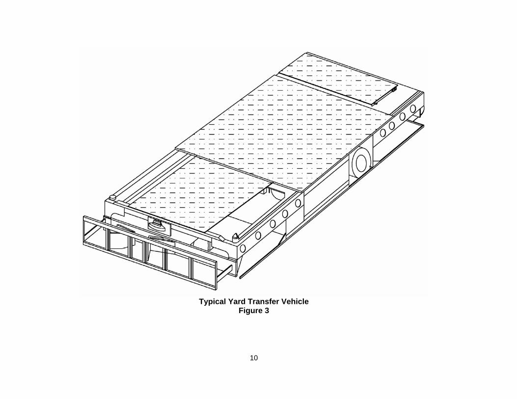
• Yard Transfer Vehicle and Facility Transfer Vehicle The Yard Transfer Vehicle (Figure 3) transports the TRUPACT-III shipping container
5
from the PAU into Room 108. The nominal dimensions of the Yard Transfer Vehicle are as follows: 17 feet long, 8 feet 1 inch wide, and 2 feet 7 inches high. The Yard Transfer Vehicle is an electric vehicle certified to carry a load of 60,000 pounds. The Facility Transfer Vehicle or a forklift will be used to transport the facility pallet and SLB2 from Room 108 to storage in the WHB or to the conveyance loading room for emplacement. The Facility Transfer Vehicle is currently described in the Permit and the weight capacity is included in Table A1-2. Like the Facility Transfer Vehicle, the Yard Transfer Vehicle is automatically guided on a predetermined path. The travel path is programmed into the computer system and Yard Transfer Vehicle / Facility Transfer Vehicle movements are guided through a wireless transmission. The computer system is programmed to control Yard Transfer Vehicle and Facility Transfer Vehicle traffic to prevent collisions should both automatic guided vehicles (i.e., Yard Transfer Vehicle, Facility Transfer Vehicle) approach the same travel segment. An operator activates the Yard Transfer Vehicle / Facility Transfer Vehicle by constantly pressing a trigger switch while following the vehicle’s movements. A laser scanner on the Yard Transfer Vehicle / Facility Transfer Vehicle emits a rotating laser beam that is reflected back by strategically positioned reflectors. This system triangulates the Yard Transfer Vehicle / Facility Transfer Vehicle position as it moves along the pre-programmed path. The Yard Transfer Vehicle / Facility Transfer Vehicle can function manually or automatically. In automatic mode, a command may be sent to the Yard Transfer Vehicle / Facility Transfer Vehicle through the central computer or a remote computer. In manual mode, a manual control can be attached directly to the Yard Transfer Vehicle / Facility Transfer Vehicle for movement outside the programmed path. The Yard Transfer Vehicle construction includes several safety features such as stop buttons located around the units and warning mechanisms that alert personnel to the proximity of the Yard Transfer Vehicle. There is a laser bumper (scanner) on the front and rear of the Yard Transfer Vehicle. The scanners sense obstructions in a pre-defined area within the Yard Transfer Vehicle path. The Yard Transfer Vehicle will slow down or stop depending on the distance from the obstruction. There is also a mechanical bumper on the Yard Transfer Vehicle that interrupts Yard Transfer Vehicle motion upon contact.
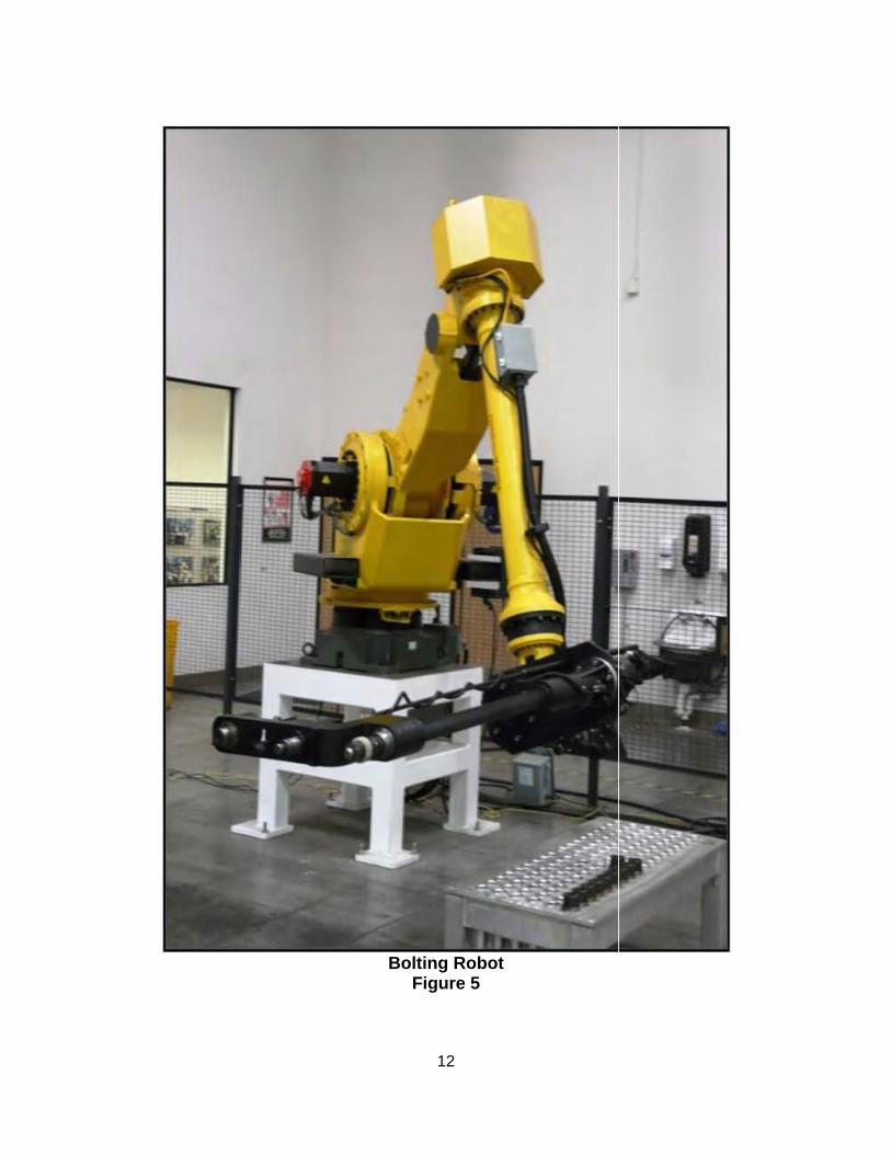
• Bolting Robot The Bolting Robot is positioned at the Bolting Station and is used to automatically remove and/or install the TRUPACT-III overpack cover and closure lid bolts. The Bolting Robot is an electro-mechanical system with an end-of-arm tool used to de-tension, remove, install, and re-tension the TRUPACT-III overpack cover and closure lid bolts.
• Vent Hood The Bolting Station also has an exhaust system that consists of a vent hood, fan, dampers, roughing filter, and duct work. The vent hood system is equivalent to the system in place at the TRUDOCK that is described in the Permit. The system will tie into the existing exhaust system in the WHB. It consists of an enclosure, which is installed

6
over the closure lid/TRUPACT-III container body interface before the closure lid is removed. The vent hood exhaust fan is interlocked with the two exhaust fans that ventilate the CH battery charger area in the CH Bay. Vent hood operation routes air through a roughing filter and into the WHB exhaust system which filters the air through a high efficiency particulate (HEPA) filter prior to discharging it to the atmosphere.
• Payload Transfer Station The Payload Transfer Station is made up of a payload lifter, Facility Transfer Vehicle with transfer table and a control system. Upon removal of the TRUPACT-III overpack cover and closure lid the TRUPACT-III is positioned at the Payload Transfer Station. The SLB2 pallet is extracted from the TRUPACT-III and placed onto the Facility Transfer Vehicle with the transfer table. The payload is then lifted from the transfer table on the Facility Transfer Vehicle. A Facility Transfer Vehicle with a Facility Pallet is located in a pre-programmed position under the SLB2 and the SLB2 is lowered onto the Facility Pallet. The facility pallet and SLB2 will be transferred to a storage location in the CH Bay or to the Conveyance Loading Room using the Facility Transfer Vehicle or a forklift.
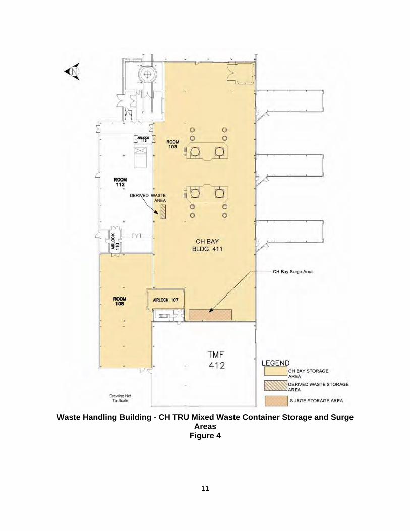
• Additional Waste Management Storage Areas (Airlock 107 and Room 108) In order to manage the TRUPACT-III, additional storage areas are required in the CH Bay. These additional areas are designated as Airlock 107 and Room 108 (Figure 4). This will increase the total storage area of the CH Bay by approximately 6,156 square feet. However, there is NO request to increase the storage capacity; only to increase the size of the waste management and storage area (locations) available within the WHB Unit at the WIPP facility. No increase in capacity is being requested for CH Surge Storage areas.
• Drum Age Criteria (DAC) DAC values have been identified for the SLB2. These values are based on an assumption of a 75% SLB2 void space. While void volumes are expected to be much smaller, this assumption covers the case where large items, not amendable to being densely packed, are packaged into an SLB2 with no other waste. The analysis that demonstrates the appropriate DAC for the SLB2 is included as Attachment C.
• Waste Emplacement There are no significant changes to the Permit for the emplacement process for the SLB2. A forklift will be used to offload the SLB2 from the underground transporter and emplaced into the waste array. Therefore, there is no need for slipsheets or push-pull attachments since the SLB2 is suitable for movement and emplacement with a forklift. The SLB2 will be emplaced on the bottom row in the repository and one additional
7
payload assembly other than an SLB2 or a Ten-Drum Overpack may be placed on top of the SLB2. The location of the SLB2 will be recorded on the mine map in accordance with the Permit. Even though the SLB2 will occupy the footprint of several payload assemblies, the disposal volume is unaffected because the SLB2 is a more efficient container.
• Equipment Inspections
Equipment Inspections have been added to Permit Attachment E for the following: o Bolting Robot o Yard Transfer Vehicle o Payload Transfer Station o Monorail Hoist o Bolting Station
The inspection of Room 108 and Airlock 107 will be performed per the “Surface Area TRU Mixed Waste Handling Area Inspection,” listed in Table E-1 (Procedure WP 05-WH1101).
The Facility Transfer Vehicle is existing equipment in the WHB and covered under procedure numbers WP 05-WH1204 and WP 05-WH1205 in Table E-1. A forklift capable of handling the TRUPACT-III has been added to Table A1-2. The inspection for this forklift will be covered by procedure WP 05-WH1201 which has been added to Table E-1. The inspection for an additional forklift capable of offloading the SLB2 from the underground transporter will be covered by procedure WP 05-WH1207 which has been added to Table E-1. 4. 20.4.1.900 NMAC (incorporating 40 CFR §270.42(b)(1)(iv)), requires the
applicant to provide the applicable information required by 40 CFR §§270.13 through 270.22, 270.62, 270.63, and 270.66.
Regulatory citations in this modification reference 20.4.1.900 NMAC (incorporating 40 CFR §§270.13-15) revised March 1, 2009. Title 40 CFR §§270.16 through 270.22, 270.62, 270.63 and 270.66 are not applicable at WIPP. Consequently, they are not included. Title 40 CFR §270.23 is applicable to the WIPP Hazardous Waste Disposal Units (HWDUs). This modification does not impact the conditions associated with the HWDUs. 5. 20.4.1.900 NMAC (incorporating 40 CFR §270.11(d)(1) and
40 CFR §270.30(k)), requires any person signing under paragraphs a and b to certify the document in accordance with 20.4.1.900 NMAC.
The transmittal letter for this PMR contains the signed certification statement in accordance with Part 1.9 of the Permit.
8
Typical TRUPACT-III Figure 1
(104 IN.)
Dimensions are nominal
(104 IN.)
Dimensions are nominal
9
Typical Standard Large Box 2
Figure 2
10
Typical Yard Transfer Vehicle
Figure 3
11
Waste Handling Building - CH TRU Mixed Waste Container Storage and Surge
Areas Figure 4
12
Bolting Robot
Figure 5
13
Payload Transfer Station
Figure 6

14
Regulatory Crosswalk Regulatory Citation(s)
20.4.1.900 NMAC (incorporating
40 CFR Part 270)
Regulatory Citation(s)
20.4.1.500 NMAC (incorporating
40 CFR Part 264)
Description of Requirement
Added or Clarified Information
Section of the HWFP or Permit
Application Yes No
§270.13 Contents of Part A permit application Attachment B Part A ✓
§270.14(b)(1) General facility description Attachment A ✓
§270.14(b)(2) §264.13(a) Chemical and physical analyses Part 2.3.1 Attachment C ✓
§270.14(b)(3) §264.13(b) Development and implementation of waste analysis plan
Part 2.3.1.1 Attachment C ✓
§264.13(c) Off-site waste analysis requirements Part 2.2.1 Attachment C ✓
§270.14(b)(5) §264.15(a-d) General inspection requirements Part 2.7 Attachment E-1a ✓
§264.174 Container inspections Attachment E-1b(1) ✓ §270.23(a)(2) §264.602 Miscellaneous units inspections Attachment E-1b
Attachment E-1b(1) ✓
§270.14(b)(6)
Request for waiver from preparedness and prevention requirements of Part 264 Subpart C
NA
§270.14(b)(7) 264 Subpart D Contingency plan requirements Part 2.12
Attachment D ✓ §264.51 Contingency plan design and
implementation Part 2.12.1 Attachment D ✓
§264.52 (a) & (c-f) Contingency plan content Attachment D ✓ §264.53 Contingency plan copies Part 2.12.2
Attachment D ✓
§264.54 Contingency plan amendment Part 2.12.3 Attachment D ✓
§264.55 Emergency coordinator Part 2.12.4 Attachment D-4a(1) ✓
§264.56 Emergency procedures Attachment D-4 ✓
§270.14(b)(8) Description of procedures, structures or equipment for:
Attachment A Part 2.11 ✓
§270.14(b)(8)(i) Prevention of hazards in unloading operations (e.g., ramps and special forklifts)
Part 2.11
✓
§270.14(b)(8)(ii) Runoff or flood prevention (e.g., berms, trenches, and dikes)
Attachment A1-1c(1) Part 2.11 ✓
§270.14(b)(8)(iii) Prevention of contamination of water supplies
Part 2.11 ✓
§270.14(b)(8)(iv) Mitigation of effects of equipment failure and power outages
Part 2.11 ✓
§270.14(b)(8)(v) Prevention of undue exposure of personnel (e.g., personal protective equipment)
Part 2.11
✓
§270.14(b)(8)(vi) §270.23(a)(2)
§264.601
Prevention of releases to the atmosphere
Part 2.11 Part 4.4 Attachment D-4e Attachment G-1a ✓
15
Regulatory Crosswalk Regulatory Citation(s)
20.4.1.900 NMAC (incorporating
40 CFR Part 270)
Regulatory Citation(s)
20.4.1.500 NMAC (incorporating
40 CFR Part 264)
Description of Requirement
Added or Clarified Information
Section of the HWFP or Permit
Application Yes No
264 Subpart C
Preparedness and Prevention
Part 2.10 ✓
§264.31 Design and operation of facility Part 2.1 ✓
§264.32 Required equipment Part 2.10.1 Attachment D ✓
§264.33 Testing and maintenance of equipment
Part 2.10.2 Attachment E-1A ✓
§264.34 Access to communication/alarm system
Attachment E-1A Part 2.10.3 ✓
§264.35 Required aisle space Part 2.10.4 ✓
§264.37 Arrangements with local authorities Attachment D-4a(3) ✓
§270.14(b)(9) §264.17(a-c) Prevention of accidental ignition or reaction of ignitable, reactive, or incompatible wastes
Part 2.9
✓
§270.14(b)(10) Traffic pattern, volume, and controls, for example: Identification of turn lanes Identification of traffic/stacking lanes, if appropriate Description of access road surface Description of access road load-bearing capacity Identification of traffic controls
Attachment A4
✓ §270.14(b) (11)(i) and (ii)
§264.18(a) Seismic standard applicability and requirements
Attachment G2-2.2 Renewal App. Sep. 2009, 270.14 Contents of Part B: General Requirements ✓
§270.14(b)(11)(iii-v) §264.18(b) 100-year floodplain standard Attachment A1-1c(1) Renewal App. Sep. 2009, 270.14 Contents of Part B: General Requirements ✓
§270.14(b) (12)
§264.16(a-e) Personnel training program Part 2.8 Attachment F ✓
§270.14(b)(13) 264 Subpart G Closure and post-closure plans Part 6 & 7 Attachment G & H ✓
§270.14(b)(13) §264.111 Closure performance standard Attachment G-1a ✓
§270.14(b)(13) §264.112(a), (b) Written content of closure plan Attachment G-1 ✓
§270.14(b)(13) §264.112(c) Amendment of closure plan Part 6.3 Attachment G-1d(4) ✓
§270.14(b)(13) §264.112(d) Notification of partial and final closure Attachment G-2a ✓
§270.14(b)(13) §264.112(e) Removal of wastes and decontamination/dismantling of equipment
Attachment G-1e(2)
✓
§270.14(b)(13) §264.113 Time allowed for closure Part 6.5 Attachment G-1d ✓
§270.14(b)(13) §264.114 Disposal/decontamination Part 6.6 Attachment G-1e(2) ✓

16
Regulatory Crosswalk Regulatory Citation(s)
20.4.1.900 NMAC (incorporating
40 CFR Part 270)
Regulatory Citation(s)
20.4.1.500 NMAC (incorporating
40 CFR Part 264)
Description of Requirement
Added or Clarified Information
Section of the HWFP or Permit
Application Yes No
§270.14(b)(13) §264.115 Certification of closure Part 6.7 Attachment G-2a ✓
§270.14(b)(13) §264.116 Survey plat Part 6.8 Attachment G-2b ✓
§270.14(b)(13) §264.117 Post-closure care and use of property Part 7.3 Attachment H-1a ✓
§270.14(b)(13) §264.118 Post-closure plan; amendment of plan Part 7.5 Attachment H-1a(1) ✓
§270.14(b)(13) §264.178 Closure/containers Part 6.9 Attachment A1-1h Attachment G-1 ✓
§270.14(b)(13) §264.601 Environmental performance standards-miscellaneous units
Attachment A-4 Attachment D-1 Attachment G-1a ✓
§270.14(b)(13) §264.603 Post-closure care Part 7.3 Attachment G-1a(3) ✓
§270.14(b)(14) §264.119 Post-closure notices Part 7.4 Attachment H-2 ✓
§270.14(b)(15) §264.142 Closure cost estimate NA ✓
§264.143 Financial assurance NA ✓
§270.14(b)(16) §264.144 Post-closure cost estimate NA ✓
§264.145 Post-closure care financial assurance NA ✓
§270.14(b)(17) §264.147 Liability insurance NA ✓
§270.14(b)(18) §264.149-150 Proof of financial coverage NA ✓
§270.14(b)(19)(i), (vi), (vii), and (x)
Topographic map requirements Map scale and date Map orientation Legal boundaries Buildings Treatment, storage, and disposal operations Run-on/run-off control systems Fire control facilities
Attachment B2 Part A Renewal App. Sep. 2009, 270.14 Contents of Part B: General Requirements
✓
§270.14(b)(19)(ii) §264.18(b) 100-year floodplain Attachment B2 Part A Renewal App. Sep. 2009, 270.14 Contents of Part B: General Requirements ✓
§270.14(b)(19)(iii) Surface waters Attachment B2 Part A Renewal App. Sep. 2009, 270.14 Contents of Part B: General Requirements ✓
17
Regulatory Crosswalk Regulatory Citation(s)
20.4.1.900 NMAC (incorporating
40 CFR Part 270)
Regulatory Citation(s)
20.4.1.500 NMAC (incorporating
40 CFR Part 264)
Description of Requirement
Added or Clarified Information
Section of the HWFP or Permit
Application Yes No
§270.14(b)(19)(iv) Surrounding land use Attachment B2 Part A Renewal App. Sep. 2009, 270.14 Contents of Part B: General Requirements ✓
§270.14(b)(19)(v) Wind rose Attachment B2 Part A Renewal App. Sep. 2009, 270.14 Contents of Part B: General Requirements ✓
§270.14(b)(19)(viii) §264.14(b) Access controls Attachment B2 Part A Renewal App. Sep. 2009, 270.14 Contents of Part B: General Requirements ✓
§270.14(b)(19)(ix) Injection and withdrawal wells Attachment B2 Part A Renewal App. Sep. 2009, 270.14 Contents of Part B: General Requirements ✓
§270.14(b)(19)(xi) Drainage on flood control barriers Attachment B2 Renewal App. Sep. 2009, 270.14 Contents of Part B: General Requirements ✓
§270.14(b)(19)(xii) Location of operational units Attachment B2 Renewal App. Sep. 2009, 270.14 Contents of Part B: General Requirements ✓
§270.14(b)(20) Other federal laws Wild and Scenic Rivers Act National Historic Preservation Act Endangered Species Act Coastal Zone Management Act Fish and Wildlife Coordination Act Executive Orders
Attachment B Renewal App. Sep. 2009, 270.14 Contents of Part B: General Requirements
✓
§270.15 §264 Subpart I Containers Part 3 Part 4.3 Attachment A1 ✓
§264.171 Condition of containers Part 3.3 Attachment A1 ✓
§264.172 Compatibility of waste with containers Part 3.4 Attachment A1 ✓
§264.173 Management of containers Part 3.5 Attachment A1 ✓

18
Regulatory Crosswalk Regulatory Citation(s)
20.4.1.900 NMAC (incorporating
40 CFR Part 270)
Regulatory Citation(s)
20.4.1.500 NMAC (incorporating
40 CFR Part 264)
Description of Requirement
Added or Clarified Information
Section of the HWFP or Permit
Application Yes No
§264.174 Inspections Part 3.7 Attachment E-1 Attachment A1-1e ✓
§270.15(a) §264.175 Containment systems Part 3.6 Attachment A1 ✓
§270.15(c) §264.176 Special requirements for ignitable or reactive waste
Attachment A1-1g Permit Part 2.1 ✓
§270.15(d) §264.177 Special requirements for incompatible wastes
Attachment A1-1g Permit Part 2.3.3.4 ✓
§264.178 Closure Part 6 Attachment G ✓
§270.15(e) §264.179 Air emission standards Part 4.4.2 Attachment N ✓
§270.23 264 Subpart X Miscellaneous units Part 1.3.1 Attachment A2-1 Attachment G1.3.1 ✓
§270.23(a) §264.601 Detailed unit description Part 4 Attachment A2 ✓
§270.23(b) §264.601 Hydrologic, geologic, and meteorologic assessments
Part 4 Attachment A2 ✓
§270.23(c) §264.601 Potential exposure pathways Part 4 Attachment A2 Attachment N ✓
§270.23(d) Demonstration of treatment effectiveness
Part 4 Attachment A2 Attachment N ✓
§264.602 Monitoring, analysis, inspection, response, reporting, and corrective action
Part 4 Attachment A2 Attachment E-1 Attachment N ✓
§264.603 Post-closure care Attachment H Attachment H 1 ✓
264 Subpart E Manifest system, record keeping, and reporting
Permit Part 1 Permit Part 2.13 & 2.14 Permit Part 4 Attachment C ✓


A-1
Attachment A Table of Changes
A-2
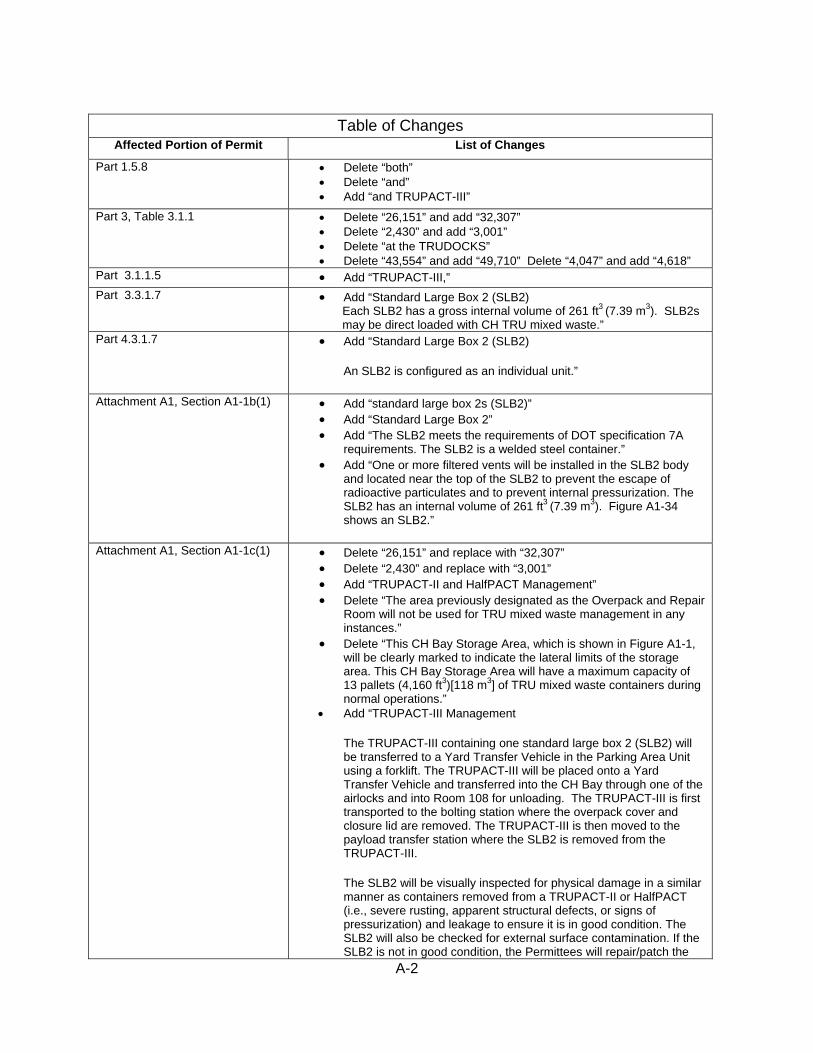
Table of Changes
Affected Portion of Permit List of Changes
Part 1.5.8 • Delete “both” • Delete “and” • Add “and TRUPACT-III”
Part 3, Table 3.1.1 • Delete “26,151” and add “32,307” • Delete “2,430” and add “3,001” • Delete “at the TRUDOCKS” • Delete “43,554” and add “49,710” Delete “4,047” and add “4,618”
Part 3.1.1.5 • Add “TRUPACT-III,” Part 3.3.1.7 • Add “Standard Large Box 2 (SLB2)
Each SLB2 has a gross internal volume of 261 ft3 (7.39 m3). SLB2s may be direct loaded with CH TRU mixed waste.”
Part 4.3.1.7 • Add “Standard Large Box 2 (SLB2)
An SLB2 is configured as an individual unit.”
Attachment A1, Section A1-1b(1) • Add “standard large box 2s (SLB2)” • Add “Standard Large Box 2” • Add “The SLB2 meets the requirements of DOT specification 7A
requirements. The SLB2 is a welded steel container.” • Add “One or more filtered vents will be installed in the SLB2 body
and located near the top of the SLB2 to prevent the escape of radioactive particulates and to prevent internal pressurization. The SLB2 has an internal volume of 261 ft3 (7.39 m3). Figure A1-34 shows an SLB2.”
Attachment A1, Section A1-1c(1) • Delete “26,151” and replace with “32,307” • Delete “2,430” and replace with “3,001” • Add “TRUPACT-II and HalfPACT Management” • Delete “The area previously designated as the Overpack and Repair
Room will not be used for TRU mixed waste management in any instances.”
• Delete “This CH Bay Storage Area, which is shown in Figure A1-1, will be clearly marked to indicate the lateral limits of the storage area. This CH Bay Storage Area will have a maximum capacity of 13 pallets (4,160 ft3)[118 m3] of TRU mixed waste containers during normal operations.”
• Add “TRUPACT-III Management
The TRUPACT-III containing one standard large box 2 (SLB2) will be transferred to a Yard Transfer Vehicle in the Parking Area Unit using a forklift. The TRUPACT-III will be placed onto a Yard Transfer Vehicle and transferred into the CH Bay through one of the airlocks and into Room 108 for unloading. The TRUPACT-III is first transported to the bolting station where the overpack cover and closure lid are removed. The TRUPACT-III is then moved to the payload transfer station where the SLB2 is removed from the TRUPACT-III.
The SLB2 will be visually inspected for physical damage in a similar manner as containers removed from a TRUPACT-II or HalfPACT (i.e., severe rusting, apparent structural defects, or signs of pressurization) and leakage to ensure it is in good condition. The SLB2 will also be checked for external surface contamination. If the SLB2 is not in good condition, the Permittees will repair/patch the
A-3
Table of Changes Affected Portion of Permit List of Changes
container in accordance with 49 CFR §173 and §178 (e.g., 49 CFR §173.28), or return the container to the generator. The Permittees may initiate local decontamination, return unacceptable containers to a DOE generator site or send the Contact-Handled Package to the third-party contractor. If local decontamination activities are opted for, the work will be conducted in the WHB Unit.
Once the SLB2 is unloaded from the TRUPACT-III in Room 108 it will be placed on a facility pallet and moved to a pallet stand or floor storage location in the CH Bay for storage or to the conveyance loading room for waste emplacement.
The CH Bay Storage Area, which is shown in Figure A1-1, will be clearly marked to indicate the lateral limits of the storage area. This CH Bay Storage Area will have a maximum capacity of 13 pallets (4,160 ft3 [118 m3]) of TRU mixed waste containers during normal operations.”
• Add “TRUPACT-III Type B Packaging
The TRUPACT-III (Figure A1-33) is an NRC-certified Type B package designed to meet the containment and shielding requirements of 10 CFR Part 71. The nominal dimensions for a TRUPACT-III are 14 feet 1 inch long, 8 feet 2 inches wide and 8 feet 8 inches high. The TRUPACT-III is specifically certified to safely transport TRU wastes packaged in SLB2s.
This package, unlike the TRUPACT-II or HalfPACT, is horizontally loaded and will be unloaded horizontally as well.
The TRUPACT-III has a bolted overpack cover that is secured to the TRUPACT-III container.
The maximum weight of a TRUPACT-III is 55,116 lbs (25,000 kg) when loaded with the maximum allowable contents of 11,486 lbs (5,210 kg).”
• Add “The payload transfer station serves as the unloading dock for TRUPACT-III and can accommodate a single TRUPACT-III package.”
• Delete “will” • Add “may” • Add “Unloading Devices” • Add “The TRUPACT-III is unloaded horizontally in Room 108. The
Payload Transfer Station, Yard Transfer Vehicle and Facility Transfer Vehicle or forklift are used to perform the unloading and movement functions. The Payload Transfer Station includes retractable arms that are used to position the SLB2 onto the Facility Transfer Vehicle and facility pallet.”
• Add “or an SLB2” • Add “or an SLB2” • Delete “or any combination thereof” • Add “Yard Transfer Vehicle
The Yard Transfer Vehicle (Figure A1-35) transports the TRUPACT-III shipping container from the PAU into the WHB and into Room 108. The Yard Transfer Vehicle is an electric vehicle with a load capacity of 60,000 pounds.”
A-4
Table of Changes Affected Portion of Permit List of Changes
Attachment A1, Section A1-1d(2) • Add “TRUPACT-IIIs” • Delete “and” • Add “which will be transported by forklift or Yard Transfer Vehicle.” • Delete “will transport them a short distance” • Add “either” • Add “or the Yard Transfer Vehicle will locate the TRUPACT-III at
the bolting station in Room 108” • Delete “where” • Add “.” • Delete “a” • Add “A” • Delete “(see)” • Delete “lifted” and replace with “removed” • Delete “TRUDOCK” • Delete “lift” and replace with “process is complete” • Delete “TRUDOCK” • Remove “TRUDOCK” from footnotes 1 and 2 • Add “or repairing” • Delete “in either a 85-gal (322 L) drum, SWB, or a TDOP” • Add “or repaired” • Add “The TRUPACT-III will hold an SLB2.” • Add “or Facility Transfer Vehicle” • Add “(see Figure A1-10)” • Add “Each facility pallet will accommodate one SLB2” • Delete “(see Figure A1-10)”
Attachment A1, Table A1-2 • Delete “CH Bay” • Add “Surface” • Add “(CH Bay forklift) 70,000 lbs. (TRUPACT-III Handler forklift)” • Add “Yard Transfer Vehicle 60,000 lbs” • Add “Standard large box 2 10,500 lbs” • Add “TRUPACT-III 43,600 lbs”
Attachment A2, Section A2-2a(1) • Add “or standard large box 2s (SLB2),” • Delete “or” • Add “or one SLB2” • Add “A forklift will be used to offload the SLB2 from the underground
transporter and emplace the waste container in the waste array.” Attachment A2, Section A2-2b • Add “a forklift or Yard Transfer Vehicle”
• Add “Each TRUPACT-III will hold one SLB2” • Add “or Facility Transfer Vehicle with transfer table” • Add “one SLB2” • Add “A forklift in the HWDU near the waste stack will be used to
remove the waste containers from the facility pallets and to place them in the waste stack using a push-pull attachment or, in the case of an SLB2, the SLB2 will be lifted from the facility pallet and placed directly on the floor of the emplacement room.”
Attachment A2, Table A2-1 • Add “Standard large box 2 10,500 lbs.” • Add “TRUPACT-III 43,600 lbs.”
Attachment A4, Section A4-3 • Add “or Yard Transfer Vehicle” • Add “or at the payload transfer station in the case of TRUPACT-III” • Add “The TRUPACT-III will hold an SLB2”
A-5
Table of Changes Affected Portion of Permit List of Changes
• Add “or Facility Transfer Vehicle with a transfer table” • Delete “,” • Add “or an SLB2” • Delete “or any combination thereof” • Add “s” to figures and Add “A4-3a and A4-3b”
Attachment C1, Section C1-1a • Add “standard large box 2s (SLB2s),” • Add “SLB2” • Add “, SLB2”
Attachment C1, Section C1-1a(1) • Add “SLB2s” Attachment C1, Table C1-5 • Add “SLB2s” Attachment C1, Table C1-8 • Add “Standard Large Box 2”
• Add “SLB2s” • Add “ and SLB2s”
Attachment C1, Table C1-9 • Add “/SLB2” • Add “6.60 x 10⁻⁴ (SLB2) and “21” • Add “/SLB2” • Add “6.60 x 10⁻⁴ (SLB2) and “56” • Add “SLB2” in footnote c
Attachment D, Section D-1d • Add “standard large box 2s (SLB2) Attachment D, Section D-1e • Delete “43,554” and add “49,710”
• Delete “4,047” and add “4,618” • Delete “26,151” and add “32,307” • Delete “2,430” and add “3,001”
Attachment D, Section D-1e(1) • Add “one SLB2” • Delete “in one of two positions”
Attachment D, Section D-4d(6) • Add “and SLB2s” Attachment E, Section E-1b(1) • Delete “Module III” and add “Part 3”
• Add “in standard large box 2 (SLB2),” • Add “or in Room 108 while still”
Attachment E, Table E-1 • Add “Bolting Robot” to System/Equipment Name • Add “Waste Handling” to Responsible Organization • Add “Preoperational See List 1” to Inspection a Frequency and Job
Title of Personnel Normally Making Inspection • Add “WP 05-WH1203 Mechanical Operability” to Procedure Number
and Inspection Criteria • Add “Yard Transfer Vehicle” to System/Equipment Name • Add “Waste Handling” to Responsible Organization • Add “Preoperational See List 1” to Inspection a Frequency and Job
Title of Personnel Normally Making Inspection • Add “WP 05-WH1205 Mechanical Operability, Deterioration, Path
clear of obstacles and Guards in proper place • Add “Payload Transfer Station” to System/Equipment Name • Add “Waste Handling” to Responsible Organization • Add “Preoperational See List 1” to Inspection a Frequency and Job
Title of Personnel Normally Making Inspection • Add “WP 05-WH1208 Mechanical Operability, Deterioration, and
Guards in proper place” • Add “Monorail Hoist” to System Equipment Name • Add “Waste Handling” to Responsible Organization • Add “Preoperational See list 8” to Inspection a Frequency and Job
Title of Personnel Normally Making Inspection

A-6
Table of Changes Affected Portion of Permit List of Changes
• Add “WP 05-WH1202 Mechanical Operability, Deterioration, Leaks/Spills”
• Add “Bolting Station” to System Equipment Name • Add “Waste Handling” to Responsible Organization • Add “Preoperational See list 1” to Inspection a Frequency and Job
Title of Personnel Normally Making Inspection • Add “WP 05-WH1209 Mechanical Operability, Deterioration, and
Guards in Proper Place” • Delete “WP 05-WH1406 and WP 05-WH1408” • Add “WP 05-WH1204 and WP 05-1205” • Add “WP 05-WH1201, WP05-WH1207,”
Attachment G3, Table G3-2 • Add “(TRUPACT-II/HalfPACT)” • Add “HP” to read as “WP 12-HP1100”
Attachment G3, Table G3-2a • Add New Table “Radiological Surveys During CH TRU Mixed Waste Processing for TRUPACT-III”
Attachment J, Table J-1 • Delete “26,151” and Add “32,307” • Delete “2,430” and Add “3,001” • Delete “at the TRUDOCKS” • Delete “43,554” and add “49,710 - and Delete “4,047” and add
“4,618” Attachment A1, Figure A1-1 • Revise Figure “Waste Handling Building-CH TRU Mixed Waste
Container Storage and Surge Areas” Attachment B3, Figure B3-3 • Revise Figure “Waste Handling Building-CH TRU Mixed Container
and Surge Areas” Attachment A1, Figure A1-33 • Add New Figure “Typical TRUPACT-III” Attachment A1, Figure A1-34 • Add New Figure “Typical Standard Large Box 2” Attachment A1, Figure A1-35 • Add New Figure “Typical Yard Transfer Vehicle” Attachment A1, Figure A1-36 • Add New Figure “Payload Transfer Station” Attachment A4, Figure A4-3a • Add New Figure “Typical Transport Route for TRUPACT-III and
Standard Large Box 2” Attachment A4, Figure A4-3b • Add New Figure “Typical Transport Route for TRUPACT-III and
Standard Large Box 2 in Room 108”
B-1
Attachment B Proposed Revised Permit Text

B-2
1.5.8 Contact Handled Packages
“Contact Handled Packages” means both TRUPACT-II, and HalfPACT and TRUPACT-III shipping containers and their contents.

B-3
3.1.1.5 Storage on Pallets
The Permittees shall store TRU mixed waste containers unloaded from the Contact-Handled Packages (TRUPACT-III, TRUPACT-II or HalfPACT shipping containers) on pallets in the WHB Unit, as described in Permit Attachment A1, Section A1-1c(1).

B-4
Table 3.1.1 - WHB Unit
Description Area Maximum Capacity
Container Equivalent
CH Bay Storage Area 26,15132,307 ft2
(2,4303,001 m2) 4,800 ft3
(135.9 m3) 13 loaded facility pallets and 4 CH Packages at the TRUDOCKS
CH Bay Surge Storage Area
included in CH Bay Storage Area
1,600 ft3 (45.3 m3)
5 loaded facility pallets
Derived Waste Storage Area
included in CH Bay Storage Area
66.3 ft3 (1.88 m3)
1 Standard Waste Box
Total for CH Waste 26,15132,307 ft2 (2,4303,001 m2)
6,466.3 ft3 183.1 m3
RH Bay 12,552 ft2 (1,166 m2)
156 ft3 (4.4 m3)
2 loaded casks and 1 drum of derived waste
Cask Unloading Room
382 ft2 (36 m2)
74 ft3 (2.1 m3)
1 loaded cask
Hot Cell 1,841 ft2 (171 m2)
94.9 ft3 (2.7 m3)
12 drums and 1 drum of derived waste
Transfer Cell 1,003 ft2 (93 m2)
31.4 ft3 (0.89 m3)
1 canister
Facility Cask Loading Room
1,625 ft2 (151 m2)
31.4 ft3 (0.89 m3)
1 canister
Total for RH Waste 17,403 ft2 (1,617 m2)
387.7 ft3 (11.0 m3)
Facility Total 43,55449,710 ft2 (4,0474,618 m2)
6,854 ft3 (194.1 m3)
B-5
3.3.1 Acceptable Storage Containers
The Permittees shall use containers that comply with the requirements for U.S. Department of Transportation shipping container regulations (49 CFR §173 - Shippers - General Requirements for Shipment and Packaging, and 49 CFR §178 - Specifications for Packaging) for storage of TRU mixed waste at WIPP. The Permittees are prohibited from storing TRU mixed waste in any container not specified in Permit Attachment A1, Section A1-1b, as set forth below:
3.3.1.7 Standard Large Box 2 (SLB2)
Each SLB2 has a gross internal volume of 261 ft3 (7.39 m3). SLB2s may be direct loaded with CH TRU mixed waste.
B-6
4.3.1 Acceptable Disposal Containers
The Permittees shall use containers that comply with the requirements for U.S. Department of Transportation shipping container regulations (49 CFR §173 - Shippers - General Requirements for Shipment and Packaging, and 49 CFR §178 - Specifications for Packaging) for disposal of TRU mixed waste at WIPP. The Permittees are prohibited from disposing TRU mixed waste in any container not specified in Permit Attachment A1 (Container Storage), Section A1-1b, as set forth below:
4.3.1.7 Standard Large Box 2 (SLB2)
An SLB2 is configured as an individual unit.
B-7
A1-1b(1) CH TRU Mixed Waste Containers
Contact handled (CH) TRU mixed waste containers will be either 55-gal (208-L) drums singly or arranged into 7-packs, 85-gal (322-L) drums singly or arranged into 4-packs, 100-gal (379 L) drums singly or arranged into 3-packs, ten-drum overpacks (TDOP), standard large box 2s (SLB2), or SWBs. A summary description of each CH TRU mixed waste container type is provided below.
Standard Large Box 2
The SLB2 meets the requirements of DOT specification 7A requirements. The SLB2 is a welded steel container.
One or more filtered vents will be installed in the SLB2 body and located near the top of the SLB2 to prevent the escape of radioactive particulates and to prevent internal pressurization. The SLB2 has an internal volume of 261 ft3 (7.39 m3). Figure A1-34 shows an SLB2.
A1-1c(1) Waste Handling Building Container Storage Unit (WHB Unit)
The Waste Handling Building (WHB) is the surface facility where TRU mixed waste handling activities will take place (Figure A1-1a). The WHB has a total area of approximately 84,000 square feet (ft2) (7,804 square meters (m2)) of which 26,151 32,307 ft2 (2,430 3,001 m2) are designated for the waste handling and container storage of CH TRU mixed waste and 17,403 ft2 (1,617 m2) are designated for handling and storage of RH TRU mixed waste, as shown in Figures A1-1, A1-14a, and A1-17a, b, c, and d. These areas are being permitted as the WHB Unit. The concrete floors are sealed with a coating that is sufficiently impervious to the chemicals in TRU mixed waste to meet the requirements of 20.4.1.500 NMAC (incorporating 40 CFR §264.175(b)(1)).
CH TRU Mixed Waste
The Contact-Handled Packages used to transport TRU mixed waste containers will be received through one of three air-lock entries to the CH Bay of the WHB Unit. The WHB heating, ventilation and air conditioning (HVAC) system maintains the interior of the WHB at a pressure lower than the ambient atmosphere to ensure that air flows into the WHB, preventing the inadvertent release of any hazardous or radioactive constituents contamination as the result of a contamination event. The doors at each end of the air lock are interlocked to prevent both from opening simultaneously and equalizing CH Bay pressure with outside atmospheric pressure.
• TRUPACT-II and HalfPACT Management
The CH Bay houses two TRUPACT-II Docks (TRUDOCKs), each equipped with overhead cranes for opening and unloading Contact-Handled Packages. The TRUDOCKs are within the TRUDOCK Storage Area of the WHB Unit. The cranes are rated to lift the Contact-Handled Packaging lids as well as their contents. The cranes are

B-8
designed to remain on their tracks and hold their load even in the event of a design-basis earthquake.
Upon receipt and removal of CH TRU mixed waste containers from the Contact-Handled Packaging, the waste containers are required to be in good condition as provided in Permit Part 3. The waste containers will be visually inspected for physical damage (severe rusting, apparent structural defects, signs of pressurization, etc.) and leakage to ensure they are good condition prior to storage. Waste containers will also be checked for external surface contamination. If a primary waste container is not in good condition, the Permittees will overpack the container, repair/patch the container in accordance with 49 CFR §173 and §178 (e.g., 49 CFR §173.28), or return the container to the generator. The Permittees may initiate local decontamination, return unacceptable containers to a DOE generator site or send the Contact-Handled Package to the third party contractor. Decontamination activities will not be conducted on containers which are not in good condition, or which are leaking. If local decontamination activities are opted for, the work will be conducted in the WHB Unit on the TRUDOCK. These processes are described in Section A1-1d. The area previously designated as the Overpack and Repair Room will not be used for TRU mixed waste management in any instances. Once unloaded from the Contact-Handled Packaging, CH TRU mixed waste containers (7-packs, 3-packs, 4-packs, SWBs, or TDOPs) are placed in one of two positions on the facility pallet or on a containment pallet. The waste containers are stacked, on the facility pallets (one- or two-high, depending on weight considerations). Waste on containment pallets will be stacked one-high. The use of facility or containment pallets will elevate the waste at least 6 in. (15 cm) from the floor surface. Pallets of waste will then be relocated to the CH Bay Storage Area of the WHB Unit for normal storage. This CH Bay Storage Area, which is shown in Figure A1-1, will be clearly marked to indicate the lateral limits of the storage area. This CH Bay Storage Area will have a maximum capacity of 13 pallets (4,160 ft3 [118 m3]) of TRU mixed waste containers during normal operations.
In addition, four Contact-Handled Packages, containing up to eight 7-packs, 3-packs, 4-packs, SWBs, or four TDOPs, may occupy positions at the TRUDOCKs. If waste containers are left in this area, they will be in the Contact-Handled Package with or without the shipping container lids removed. The maximum volume of waste in containers in four Contact-Handled Packages is 640 ft3 (18.1 m3).
• TRUPACT-III Management
The TRUPACT-III containing one standard large box 2 (SLB2) will be transferred to a Yard Transfer Vehicle in the Parking Area Unit using a forklift. The TRUPACT-III will be placed onto a Yard Transfer Vehicle and transferred into the CH Bay through one of the airlocks and into Room 108 for unloading. The TRUPACT-III is first transported to the bolting station where the overpack cover and closure lid are removed. The TRUPACT-III is then moved to the payload transfer station where the SLB2 is removed from the TRUPACT-III.
The SLB2 will be visually inspected for physical damage in a similar manner as containers removed from a TRUPACT-II or HalfPACT (i.e., severe rusting, apparent structural defects, or signs of pressurization) and leakage to ensure it is in good condition. The SLB2 will also be checked for external surface contamination. If the SLB2
B-9
is not in good condition, the Permittees will repair/patch the container in accordance with 49 CFR §173 and §178 (e.g., 49 CFR §173.28), or return the container to the generator. The Permittees may initiate local decontamination, return unacceptable containers to a DOE generator site or send the Contact-Handled Package to the third-party contractor. If local decontamination activities are opted for, the work will be conducted in the WHB Unit.
Once the SLB2 is unloaded from the TRUPACT-III in Room 108 it will be placed on a facility pallet and moved to a pallet stand or floor storage location in the CH Bay for storage or to the conveyance loading room for waste emplacement.
The CH Bay Storage Area, which is shown in Figure A1-1, will be clearly marked to indicate the lateral limits of the storage area. This CH Bay Storage Area will have a maximum capacity of 13 pallets (4,160 ft3 [118 m3]) of TRU mixed waste containers during normal operations.
HalfPACT Type B Packaging
The HalfPACT (Figure A1-8b) is a double-contained right cylindrical shipping container 7.8 ft (2.4 m) in diameter and 7.6 ft (2.3 m) high. It meets NRC Type B shipping container requirements and has successfully completed rigorous container-integrity tests. The payload consists of approximately 7,600 lbs (3,500 kg) gross weight in up to seven 55-gal (208-L) drums, one SWB, or four 85-gallon drums. TRUPACT-III Type B Packaging
The TRUPACT-III (Figure A1-33) is an NRC-certified Type B package designed to meet the containment and shielding requirements of 10 CFR Part 71. The nominal dimensions for a TRUPACT-III are 14 feet 1 inch long, 8 feet 2 inches wide and 8 feet 8 inches high. The TRUPACT-III is specifically certified to safely transport TRU wastes packaged in SLB2s.
This package, unlike the TRUPACT-II or HalfPACT, is horizontally loaded and will be unloaded horizontally as well.
The TRUPACT-III has a bolted overpack cover that is secured to the TRUPACT-III container.
The maximum weight of a TRUPACT-III is 55,116 lbs (25,000 kg) when loaded with the maximum allowable contents of 11,486 lbs (5,210 kg).
Unloading Docks
Each TRUDOCK is designed to accommodate up to two Contact-Handled Packages. The TRUDOCK functions as a work platform, providing TRU mixed waste handling personnel easy access to the container during unloading operations (see Figure A1-1a) (Also see Drawing 41-M-001-W in Appendix D3 of the WIPP RCRA Part B Permit Application (DOE, 1997a)).
The payload transfer station serves as the unloading dock for TRUPACT-III and can accommodate a single TRUPACT-III package.

B-10
Forklifts
Forklifts willmay be used to transfer the Contact-Handled Packages into the WHB Unit and may be used to transfer palletized CH TRU mixed waste containers to the Facility Transfer Vehicle. Another forklift will be used for general-purpose transfer operations. This forklift has attachments and adapters to handle individual TRU mixed waste containers, if required.
Cranes, Unloading Devices, and Adjustable Center-of-Gravity Lift Fixtures
At each TRUDOCK, an overhead bridge crane is used with a specially designed lift fixture for disassembly of the Contact-Handled Packages. Separate lifting attachments have been specifically designed to accommodate SWBs and TDOPs. The lift fixture, attached to the crane, has built-in level indicators and two counterweights that can be moved to adjust the center of gravity of unbalanced loads and to keep them level.
The TRUPACT-III is unloaded horizontally in Room 108. The Payload Transfer Station, Yard Transfer Vehicle and Facility Transfer Vehicle or forklift are used to perform the unloading and movement functions. The Payload Transfer Station includes retractable arms that are used to position the SLB2 onto the Facility Transfer Vehicle and facility pallet.
Facility or Containment Pallets
The facility pallet is a fabricated steel unit designed to support 7-packs, 4-packs, or 3-packs of drums, SWBs, TDOPs, or an SLB2, and has a rated load of 25,000 lbs. (11,430 kg). The facility pallet will accommodate up to four 7-packs, four 3-packs, or four 4-packs of drums or four SWBs (in two stacks of two units), two TDOPs, or an SLB2. or any combination thereof. Loads are secured to the facility pallet during transport to the emplacement area. Facility pallets are shown in Figure A1-10. Fork pockets in the side of the pallet allow the facility pallet to be lifted and transferred by forklift to prevent direct contact between TRU mixed waste containers and forklift tines. This arrangement reduces the potential for puncture accidents. Facility pallets may also be moved by Facility Transfer Vehicles. WIPP facility operational documents define the operational load of the facility pallet to ensure that the rated load of a facility pallet is not exceeded.
Containment pallets are fabricated units having a containment capacity of at least ten percent of the volume of the containers and designed to support a minimum of either a single drum, a single SWB or a single TDOP. The pallets will have a rated load capacity of equal to or greater than the gross weight limit of the container(s) to be supported on the pallet. Loads are secured to the containment pallet during transport. A typical containment pallet is shown in Figure A1-10a. Fork pockets in the side of the pallet allow the containment pallet to be lifted and transferred by forklift. WIPP facility operational documents define the operational load of the containment pallet to assure that the rated load of a containment pallet is not exceeded.
Facility Transfer Vehicle
The facility transfer vehicle is a battery or electric powered automated vehicle that either operates on tracks or has an on-board guidance system that allows the vehicle to operate on the floor of the WHB. It is designed with a flat bed that has adjustable height capability and may transfer waste payloads on facility pallets or off the facility pallet stands in the CH Bay storage

B-11
area, and on and off the waste shaft conveyance by raising and lowering the bed (see Figure A1-11).
Yard Transfer Vehicle
The Yard Transfer Vehicle (Figure A1-35) transports the TRUPACT-III shipping container from the PAU into the WHB and into Room 108. The Yard Transfer Vehicle is an electric vehicle with a load capacity of 60,000 pounds.
A1-1d(2) CH TRU Mixed Waste Handling CH TRU mixed waste containers will arrive by tractor-trailer at the WIPP facility in sealed shipping containers (e.g., TRUPACT-IIIs, TRUPACT-IIs or HalfPACTs) (see Figure A1-12), at which time they will undergo security and radiological checks and shipping documentation reviews. A forklift will remove the Contact-Handled Packages and which will be transported by forklift or Yard Transfer Vehicle will transport them a short distance through an air lock that is designed to maintain differential pressure in the WHB. The forklift will place the shipping containers at either one of the two TRUDOCKs in the TRUDOCK Storage Area of the WHB Unit or the Yard Transfer Vehicle will locate the TRUPACT-III at the bolting station in Room 108, where. aAn external survey of the Contact-Handled Package inner vessel (see Figure A1-8a and A1-8b) will be performed as the outer containment vessel lid is removed lifted. The inner vessel lid will be placed under the TRUDOCK Vent Hood System (VHS), and the contents will be surveyed during and after this process is complete lift. The TRUDOCK VHS3 is attached to the Contact-Handled Package to provide atmospheric control and confinement of headspace gases at their source. It also prevents potential personnel exposure and facility contamination due to the spread of radiologically contaminated airborne dust particles and minimizes personnel exposure to VOCs.
For area contamination, once the area is cleaned up and is shown to be radiologically clean, it will be sampled for the presence of hazardous waste residues. If the area is large, a sampling plan will be developed which incorporates the guidance of EPA’s SW 846 in selecting random samples over large areas. Selection of constituents for sampling analysis will be based on information (in the WWIS) about the waste that was spilled and information on cleanup procedures. If the area is small, swipes will be used. If the results of the analysis show that residual contamination remains, a decision will be made whether further cleaning will be beneficial or whether final clean up shall be deferred until closure. For example, if hazardous constituents react with the floor coating and are essentially nonremovable without removing the
3 The TRU mixed waste container headspace may contain radiologically contaminated airborne dust particles. 1. Without the TRUDOCK VHS, a potential mechanism will exist to spread contamination (if present) in the immediate CH TRU
mixed waste handling area, because lid removal will immediately expose headspace gases to prevailing air currents induced by the building ventilation system.
2. With the VHS, a confined and controlled set of prevailing air currents will be induced by the system blower. The TRUDOCK VHS will function as a local exhaust system to effectively control radiologically contaminated airborne dust particles (and VOCs) at essentially atmospheric pressure conditions.
Functionally, the TRUDOCK VHS will draw the TRU mixed waste container headspace gases, convey them through a HEPA filter, and ultimately duct them through the WHB exhaust ventilation system. VOCs will pass through the HEPA filter and will be conveyed to the ventilation exhaust duct system. The system principally consists of a functional aggregation of 1) vent hood assembly, 2) HEPA filter assemblies (to capture any airborne radioactive particles), 3) blower (to provide forced airflow), 4) ductwork, and 5) flexible hose.
B-12
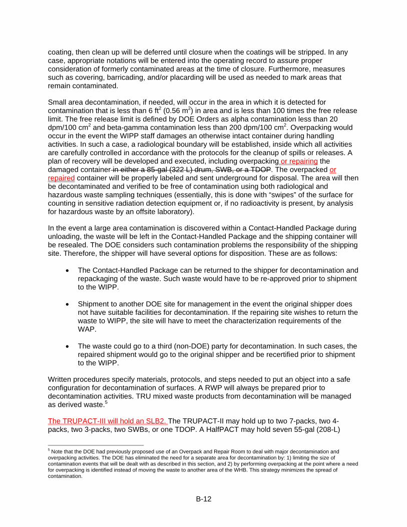
coating, then clean up will be deferred until closure when the coatings will be stripped. In any case, appropriate notations will be entered into the operating record to assure proper consideration of formerly contaminated areas at the time of closure. Furthermore, measures such as covering, barricading, and/or placarding will be used as needed to mark areas that remain contaminated.
Small area decontamination, if needed, will occur in the area in which it is detected for contamination that is less than 6 ft2 (0.56 m2) in area and is less than 100 times the free release limit. The free release limit is defined by DOE Orders as alpha contamination less than 20 dpm/100 cm2 and beta-gamma contamination less than 200 dpm/100 cm2. Overpacking would occur in the event the WIPP staff damages an otherwise intact container during handling activities. In such a case, a radiological boundary will be established, inside which all activities are carefully controlled in accordance with the protocols for the cleanup of spills or releases. A plan of recovery will be developed and executed, including overpacking or repairing the damaged container in either a 85-gal (322 L) drum, SWB, or a TDOP. The overpacked or repaired container will be properly labeled and sent underground for disposal. The area will then be decontaminated and verified to be free of contamination using both radiological and hazardous waste sampling techniques (essentially, this is done with “swipes” of the surface for counting in sensitive radiation detection equipment or, if no radioactivity is present, by analysis for hazardous waste by an offsite laboratory).
In the event a large area contamination is discovered within a Contact-Handled Package during unloading, the waste will be left in the Contact-Handled Package and the shipping container will be resealed. The DOE considers such contamination problems the responsibility of the shipping site. Therefore, the shipper will have several options for disposition. These are as follows:
• The Contact-Handled Package can be returned to the shipper for decontamination and repackaging of the waste. Such waste would have to be re-approved prior to shipment to the WIPP.
• Shipment to another DOE site for management in the event the original shipper does not have suitable facilities for decontamination. If the repairing site wishes to return the waste to WIPP, the site will have to meet the characterization requirements of the WAP.
• The waste could go to a third (non-DOE) party for decontamination. In such cases, the repaired shipment would go to the original shipper and be recertified prior to shipment to the WIPP.
Written procedures specify materials, protocols, and steps needed to put an object into a safe configuration for decontamination of surfaces. A RWP will always be prepared prior to decontamination activities. TRU mixed waste products from decontamination will be managed as derived waste.5
The TRUPACT-III will hold an SLB2. The TRUPACT-II may hold up to two 7-packs, two 4-packs, two 3-packs, two SWBs, or one TDOP. A HalfPACT may hold seven 55-gal (208-L)
5 Note that the DOE had previously proposed use of an Overpack and Repair Room to deal with major decontamination and overpacking activities. The DOE has eliminated the need for a separate area for decontamination by: 1) limiting the size of contamination events that will be dealt with as described in this section, and 2) by performing overpacking at the point where a need for overpacking is identified instead of moving the waste to another area of the WHB. This strategy minimizes the spread of contamination.
B-13
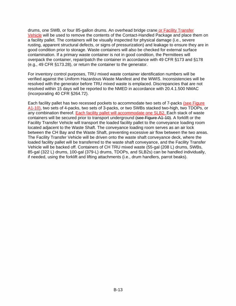
drums, one SWB, or four 85-gallon drums. An overhead bridge crane or Facility Transfer Vehicle will be used to remove the contents of the Contact-Handled Package and place them on a facility pallet. The containers will be visually inspected for physical damage (i.e., severe rusting, apparent structural defects, or signs of pressurization) and leakage to ensure they are in good condition prior to storage. Waste containers will also be checked for external surface contamination. If a primary waste container is not in good condition, the Permittees will overpack the container, repair/patch the container in accordance with 49 CFR §173 and §178 (e.g., 49 CFR §173.28), or return the container to the generator.
For inventory control purposes, TRU mixed waste container identification numbers will be verified against the Uniform Hazardous Waste Manifest and the WWIS. Inconsistencies will be resolved with the generator before TRU mixed waste is emplaced. Discrepancies that are not resolved within 15 days will be reported to the NMED in accordance with 20.4.1.500 NMAC (incorporating 40 CFR §264.72).
Each facility pallet has two recessed pockets to accommodate two sets of 7-packs (see Figure A1-10), two sets of 4-packs, two sets of 3-packs, or two SWBs stacked two-high, two TDOPs, or any combination thereof. Each facility pallet will accommodate one SLB2. Each stack of waste containers will be secured prior to transport underground (see Figure A1-10). A forklift or the Facility Transfer Vehicle will transport the loaded facility pallet to the conveyance loading room located adjacent to the Waste Shaft. The conveyance loading room serves as an air lock between the CH Bay and the Waste Shaft, preventing excessive air flow between the two areas. The Facility Transfer Vehicle will be driven onto the waste shaft conveyance deck, where the loaded facility pallet will be transferred to the waste shaft conveyance, and the Facility Transfer Vehicle will be backed off. Containers of CH TRU mixed waste (55-gal (208 L) drums, SWBs, 85-gal (322 L) drums, 100-gal (379-L) drums, TDOPs, and SLB2s) can be handled individually, if needed, using the forklift and lifting attachments (i.e., drum handlers, parrot beaks).
B-14
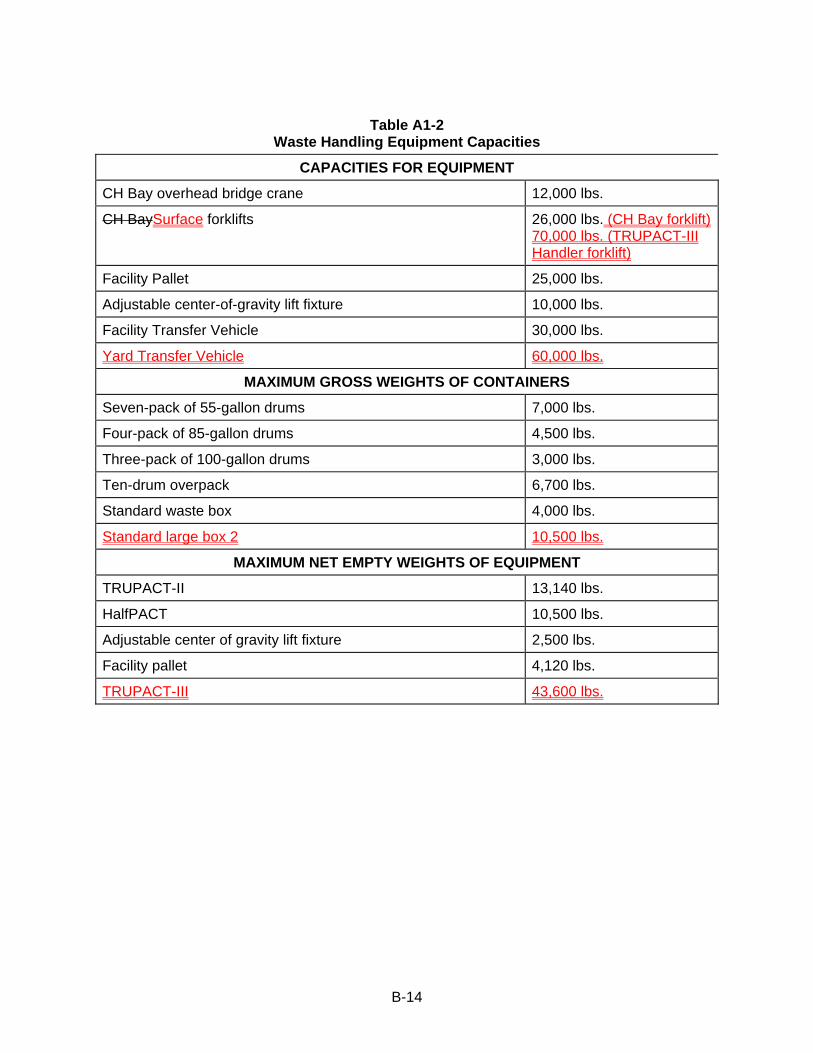
Table A1-2
Waste Handling Equipment Capacities
CAPACITIES FOR EQUIPMENT
CH Bay overhead bridge crane 12,000 lbs.
CH BaySurface forklifts 26,000 lbs. (CH Bay forklift) 70,000 lbs. (TRUPACT-III Handler forklift)
Facility Pallet 25,000 lbs.
Adjustable center-of-gravity lift fixture 10,000 lbs.
Facility Transfer Vehicle 30,000 lbs.
Yard Transfer Vehicle 60,000 lbs.
MAXIMUM GROSS WEIGHTS OF CONTAINERS
Seven-pack of 55-gallon drums 7,000 lbs.
Four-pack of 85-gallon drums 4,500 lbs.
Three-pack of 100-gallon drums 3,000 lbs.
Ten-drum overpack 6,700 lbs.
Standard waste box 4,000 lbs.
Standard large box 2 10,500 lbs.
MAXIMUM NET EMPTY WEIGHTS OF EQUIPMENT
TRUPACT-II 13,140 lbs.
HalfPACT 10,500 lbs.
Adjustable center of gravity lift fixture 2,500 lbs.
Facility pallet 4,120 lbs.
TRUPACT-III 43,600 lbs.
B-15
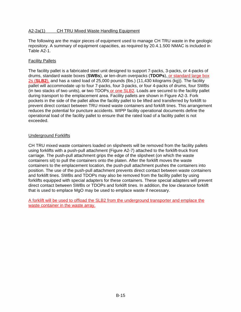
A2-2a(1) CH TRU Mixed Waste Handling Equipment The following are the major pieces of equipment used to manage CH TRU waste in the geologic repository. A summary of equipment capacities, as required by 20.4.1.500 NMAC is included in Table A2-1. Facility Pallets The facility pallet is a fabricated steel unit designed to support 7-packs, 3-packs, or 4-packs of drums, standard waste boxes (SWBs), or ten-drum overpacks (TDOPs), or standard large box 2s (SLB2), and has a rated load of 25,000 pounds (lbs.) (11,430 kilograms (kg)). The facility pallet will accommodate up to four 7-packs, four 3-packs, or four 4-packs of drums, four SWBs (in two stacks of two units), or two TDOPs or one SLB2. Loads are secured to the facility pallet during transport to the emplacement area. Facility pallets are shown in Figure A2-3. Fork pockets in the side of the pallet allow the facility pallet to be lifted and transferred by forklift to prevent direct contact between TRU mixed waste containers and forklift tines. This arrangement reduces the potential for puncture accidents. WIPP facility operational documents define the operational load of the facility pallet to ensure that the rated load of a facility pallet is not exceeded. Underground Forklifts CH TRU mixed waste containers loaded on slipsheets will be removed from the facility pallets using forklifts with a push-pull attachment (Figure A2-7) attached to the forklift-truck front carriage. The push-pull attachment grips the edge of the slipsheet (on which the waste containers sit) to pull the containers onto the platen. After the forklift moves the waste containers to the emplacement location, the push-pull attachment pushes the containers into position. The use of the push-pull attachment prevents direct contact between waste containers and forklift tines. SWBs and TDOPs may also be removed from the facility pallet by using forklifts equipped with special adapters for these containers. These special adapters will prevent direct contact between SWBs or TDOPs and forklift tines. In addition, the low clearance forklift that is used to emplace MgO may be used to emplace waste if necessary. A forklift will be used to offload the SLB2 from the underground transporter and emplace the waste container in the waste array.

B-16
A2-2b Geologic Repository Process Description
Prior to receipt of TRU mixed waste at the WIPP facility, waste operators will be thoroughly trained in the safe use of TRU mixed waste handling and transport equipment. The training will include both classroom training and on-the-job training. CH TRU Mixed Waste Emplacement
CH TRU mixed waste containers will arrive by tractor-trailer at the WIPP facility in sealed shipping containers (e.g., TRUPACT-IIs or HalfPACTs), at which time they will undergo security and radiological checks and shipping documentation reviews. The trailers carrying the shipping containers will be stored temporarily at the Parking Area Container Storage Unit (Parking Area Unit). A forklift will remove the Contact Handled Packages from the transport trailers and a forklift or Yard Transfer Vehicle will transport them into the Waste Handling Building Container Storage Unit for unloading of the waste containers. Each TRUPACT-III will hold one SLB2. Each TRUPACT-II may hold up to two 7-packs, two 4-packs, two 3-packs, two SWBs, or one TDOP. Each HalfPACT may hold up to seven 55-gal (208 L) drums, one SWB, or four 85-gal (322 L) drums. An overhead bridge crane or Facility Transfer Vehicle with transfer table will be used to remove the waste containers from the Contact Handled Packaging and place them on a facility or containment pallet. Each facility pallet has two recessed pockets to accommodate two sets of 7-packs, two sets of 3-packs, two sets of 4-packs, two SWBs stacked two-high, one SLB2 or two TDOPs. Each stack of waste containers will be secured prior to transport underground (see Figure A2-3). A forklift or the facility transfer vehicle will transport the loaded facility pallet to the conveyance loading room adjacent to the Waste Shaft. The facility transfer vehicle will be driven onto the waste shaft conveyance deck, where the loaded facility pallet will be transferred to the waste shaft conveyance, and the facility transfer vehicle will be backed off. Containers of CH TRU mixed waste (55-gal (208 L) drums, SWBs, 85-gal (322 L) drums, 100-gal (379 L) drums, and TDOPs) can be handled individually, if needed, using the forklift and lifting attachments (i.e., drum handlers, parrot beaks).
The waste shaft conveyance will lower the loaded facility pallet to the underground. At the waste shaft station, the CH TRU underground transporter will back up to the waste shaft conveyance, and the facility pallet will be transferred from the waste shaft conveyance onto the transporter (see Figure A2-6). The transporter will then move the facility pallet to the appropriate Underground HWDU for emplacement. The underground waste transporter is equipped with a fire suppression system, rupture-resistant diesel fuel tanks, and reinforced fuel lines to minimize the potential for a fire involving the fuel system.
A forklift in the HWDU near the waste stack will be used to remove the waste containers from the facility pallets and to place them in the waste stack using a push-pull attachment or, in the case of an SLB2, the SLB2 will be lifted from the facility pallet and placed directly on the floor of the emplacement room. The waste will be emplaced room by room in Panels 1 through 8. Each panel will be closed off when filled. If a waste container is damaged during the Disposal Phase, it will be immediately overpacked or repaired. The CH TRU mixed waste containers will be continuously vented. The filter vents will allow aspiration, preventing internal pressurization of the container and minimizing the buildup of flammable gas concentrations.

B-17
Table A2-1
CH TRU Mixed Waste Handling Equipment Capacities
Capacities for EquipmentFacility Pallet 25,000 lbs.
Facility Transfer Vehicle 26,000 lbs.
Underground transporter 28,000 lbs.
Underground forklift 12,000 lbs.
Maximum Gross Weights of Containers Seven-pack of 55-gallon drums 7,000 lbs.
Four-pack of 85-gallon drums 4,500 lbs.
Three-pack of 100-gallon drums 3,000 lbs.
Ten-drum overpack 6,700 lbs.
Standard waste box 4,000 lbs.
Standard large box 2 10.500 lbs.
Maximum Net Empty Weights of Equipment TRUPACT-II 13,140 lbs.
HalfPACT 10,5000 lbs.
Facility pallet 4,120 lbs.
TRUPACT-III 43,600 lbs.
B-18
A4-3 Waste Handling Building Traffic CH TRU mixed waste will arrive by tractor-trailer at the WIPP facility in sealed Contact Handled Packages. Upon receipt, security checks, radiological surveys, and shipping documentation reviews will be performed. A forklift or Yard Transfer Vehicle will remove the Contact Handled Packages and transport them a short distance through an air lock that is designed to maintain differential pressure in the WHB. The forklift or Yard Transfer Vehicle will place the shipping containers at one of the two TRUPACT-II unloading docks (TRUDOCK) inside the WHB or at the payload transfer station in the case of TRUPACT-III.
The TRUPACT-III will hold an SLB2. The TRUPACT-II may hold up to two 55-gallon drum seven-packs, two 85-gallon drum four-packs, two 100-gallon drum three-packs, two standard waste boxes (SWB), or one ten-drum overpack (TDOP). A HalfPACT may hold seven 55-gallon drums, one SWB, or four 85-gallon drums. A six-ton overhead bridge crane or Facility Transfer Vehicle with a transfer table will be used to remove the contents of the Contact Handled Package. Waste containers will be surveyed for radioactive contamination and decontaminated or returned to the Contact Handled Package as necessary.
Each facility pallet will accommodate four 55-gallon drum seven-packs, four SWBs, four 85-gallon drum four-packs, four 100-gallon drum three-packs, two TDOPs, or an SLB2, or any combination thereof. Waste containers will be secured to the facility pallet prior to transfer. A forklift or Facility Transfer Vehicle will transport the loaded facility pallet the air lock at the Waste Shaft (Figures A4-3, A4-3a and A4-3b). The Facility Transfer Vehicle will be driven onto the waste shaft conveyance deck, where the loaded facility pallet will be transferred to the waste shaft conveyance and downloaded for emplacement.
B-19
C1-1a Method Requirements The Permittees shall require all headspace-gas sampling be performed in an appropriate radiation containment area on waste containers that are in compliance with the container equilibrium requirements (i.e., 72 hours at 18° C or higher).
For those waste streams without an acceptable knowledge (AK) Sufficiency Determination approved by the U.S. Department of Energy (DOE), containers shall be randomly selected from waste streams designated as summary category S5000 (Debris waste) and shall be categorized under one of the sampling scenarios shown in Table C1-5 and depicted in Figure C1-1. If the container is categorized under Scenario 1, the applicable drum age criteria (DAC) from Table C1-6 must be met prior to headspace gas sampling. If the container is categorized under Scenario 2, the applicable Scenario 1 DAC from Table C1-6 must be met prior to venting the container and then the applicable Scenario 2 DAC from Table C1-7 must be met after venting the container. The DAC for Scenario 2 containers that contain filters or rigid liner vent holes other than those listed in Table C1-7 shall be determined using footnotes “a” and “b” in Table C1-7. Containers that have not met the Scenario 1 DAC at the time of venting must be categorized under Scenario 3. Containers categorized under Scenario 3 must be placed into one of the Packaging Configuration Groups listed in Table C1-8. If a specific packaging configuration cannot be determined based on the data collected during packaging and/or repackaging (Attachment C, Section C-3d(1)), a conservative default Packaging Configuration Group of 3 for 55-gallon drums, 6 for Standard Waste Boxes (SWBs), standard large box 2s (SLB2s), and ten-drum overpacks (TDOPs), and 8 for 85-gallon and 100-gallon drums must be assigned, provided the drums do not contain pipe component packaging. If a container is designated as a Packaging Configuration Group 4 (i.e., a pipe component), the headspace gas sample must be taken from the pipe component headspace. Drums, TDOPs, SLB2s, or SWBs that contain compacted 55-gallon drums containing a rigid liner may not be disposed of under any packaging configuration unless headspace gas sampling was performed before compaction in accordance with this waste analysis plan (WAP). The DAC for Scenario 3 containers that contain rigid liner vent holes that are undocumented during packaging, repackaging, and/or venting (Section C1-1a[4][ii]) shall be determined using the default conditions in footnote “b” in Table C1-9.The DAC for Scenario 3 containers that contain filters that are either undocumented or are other than those listed in Table C1-9 shall be determined using footnote ‘a’ in Table C1-9. Each of the Scenario 3 containers shall be sampled for headspace gas after waiting the DAC in Table C1-9 based on its packaging configuration (note: Packaging Configuration Groups 4, 5, 6, 7, and 8 are not summary category group dependent, and 85-gallon drum, 100-gallon drum, SWB, SLB2, and TDOP requirements apply when the 85-gallon drum, 100-gallon drum, SWB, SLB2, or TDOP is used for the direct loading of waste).
C1-1a(1) General Requirements The determination of packaging configuration consists of identifying the number of confinement layers and the identification of rigid poly liners when present. Generator/storage sites shall use either the default conditions specified in Tables C1-7 through C1-9 for retrievably stored waste or the data documented during packaging, repackaging, and/or venting (Section C1-1a[4][ii]) for determining the appropriate DAC for each container from which a headspace gas sample is collected. These drum age criteria are to ensure that the container contents have reached 90 percent of steady state concentration within each layer of confinement (Lockheed, 1995; BWXT, 2000). The following information must be reported in the headspace gas sampling documents for each container from which a headspace gas sample is collected:
B-20
• sampling scenario from Table C1-5 and associated information from Tables C1-6 and/or Table C1-7;
• the packaging configuration from Table C1-8 and associated information from Table C1-9, including the diameter of the rigid liner vent hole, the number of inner bags, the number of liner bags, the presence/absence of drum liner, and the filter hydrogen diffusivity,
• the permit-required equilibrium time,
• the drum age,
• for supercompacted waste, both
- the absence of rigid liners in the compacted 55-gallon drums which have not been headspace gas sampled in accordance with this permit prior to compaction, and
- the absence of layers of confinement must be documented in the WWIS if Packaging Configuration Group 7 is used.
For all retrievably stored waste containers, the rigid liner vent hole diameter must be assumed to be 0.3 inches unless a different size is documented during drum venting or repackaging. For all retrievably stored waste containers, the filter hydrogen diffusivity must be assumed to be the most restrictive unless container-specific information clearly identifies a filter model and/or diffusivity characteristic that is less restrictive. For all retrievably stored waste containers that have not been repackaged, acceptable knowledge shall not be used to justify any packaging configuration less conservative than the default (i.e., Packaging Configuration Group 3 for 55-gallon drums, 6 for SWBs, SLB2s, and TDOPs, and 8 for 85-gallon and 100-gallon drums). For information reporting purposes listed above, sites may report the default packaging configuration for retrievably stored waste without further verification.
All waste containers with unvented rigid containers greater than 4 liters (exclusive of rigid poly liners) shall be subject to innermost layer of containment sampling or shall be vented prior to initiating drum age and equilibrium criteria. When sampling the rigid poly liner under Scenario 1, the sampling device must form an airtight seal with the rigid poly liner to ensure that a representative sample is collected (using a sampling needle connected to the sampling head to pierce the rigid poly liner, and that allows for the collection of a representative sample, satisfies this requirement). The configuration of the containment area and remote-handling equipment at each sampling facility are expected to differ. Headspace-gas samples will be analyzed for the analytes listed in Table C3-2 of Permit Attachment C3. If additional packaging configurations are identified, an appropriate permit modification will be submitted to incorporate the DAC using the methodology in BWXT (2000). Consistent with footnote “a” in Table C1-8, any waste container selected for headspace gas sampling that cannot be assigned a packaging configuration specified in Table C1-8 shall be assigned a conservative default packaging configuration.
Drum age criteria apply only to 55-gallon drums, 85-gallon drums, 100-gallon drums, standard waste boxes, SLB2s, and TDOPs. Drum age criteria for all other container types must be established through permit modification prior to performing headspace gas sampling.
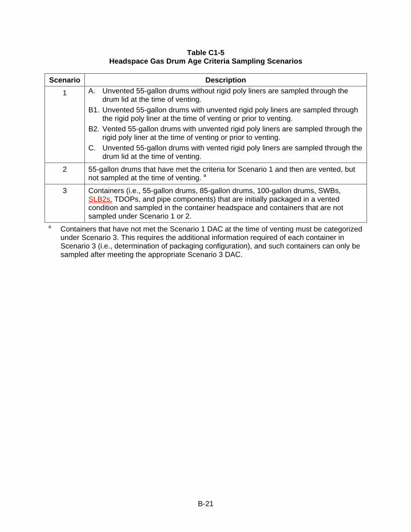
B-21
Table C1-5 Headspace Gas Drum Age Criteria Sampling Scenarios
Scenario Description
1 A. Unvented 55-gallon drums without rigid poly liners are sampled through the drum lid at the time of venting.
B1. Unvented 55-gallon drums with unvented rigid poly liners are sampled through the rigid poly liner at the time of venting or prior to venting.
B2. Vented 55-gallon drums with unvented rigid poly liners are sampled through the rigid poly liner at the time of venting or prior to venting.
C. Unvented 55-gallon drums with vented rigid poly liners are sampled through the drum lid at the time of venting.
2 55-gallon drums that have met the criteria for Scenario 1 and then are vented, but not sampled at the time of venting. a
3 Containers (i.e., 55-gallon drums, 85-gallon drums, 100-gallon drums, SWBs, SLB2s, TDOPs, and pipe components) that are initially packaged in a vented condition and sampled in the container headspace and containers that are not sampled under Scenario 1 or 2.
a Containers that have not met the Scenario 1 DAC at the time of venting must be categorized under Scenario 3. This requires the additional information required of each container in Scenario 3 (i.e., determination of packaging configuration), and such containers can only be sampled after meeting the appropriate Scenario 3 DAC.
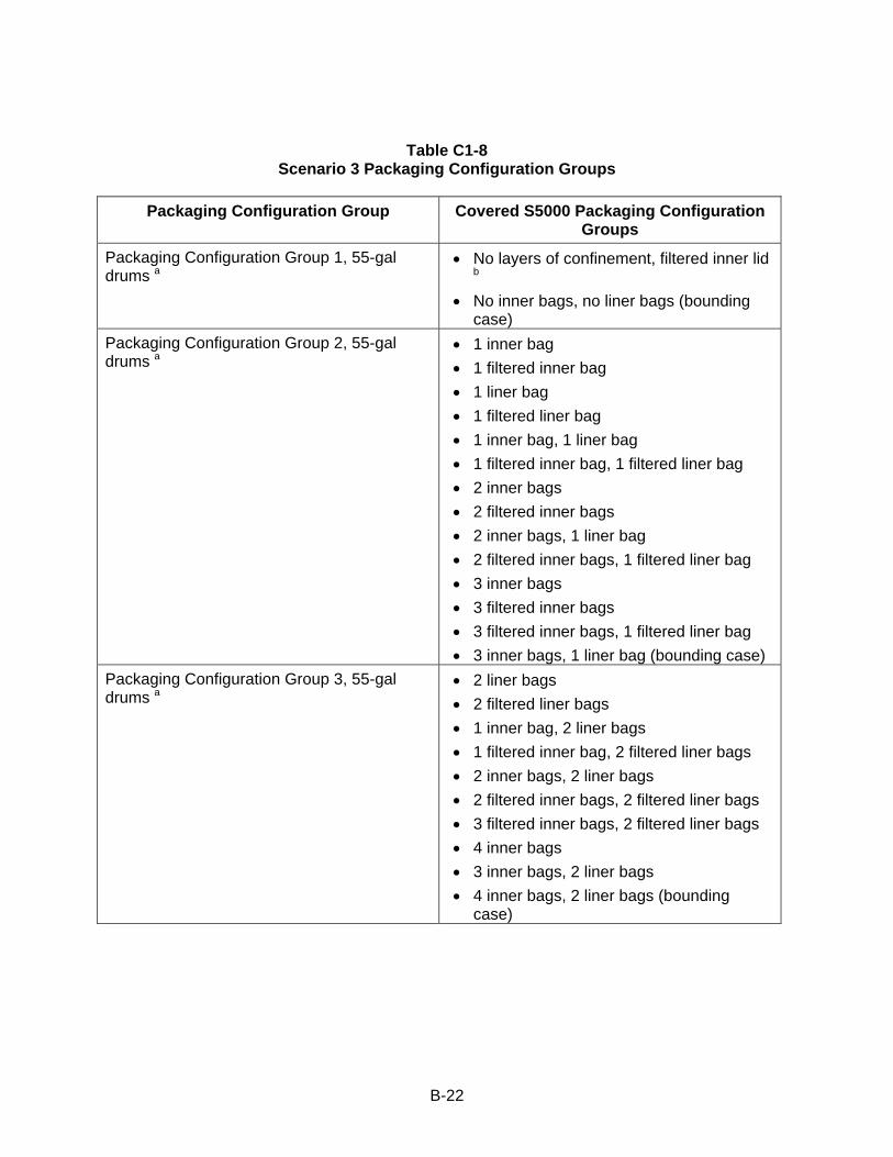
B-22
Table C1-8 Scenario 3 Packaging Configuration Groups
Packaging Configuration Group Covered S5000 Packaging Configuration
Groups
Packaging Configuration Group 1, 55-gal drums a
• No layers of confinement, filtered inner lid
b • No inner bags, no liner bags (bounding
case) Packaging Configuration Group 2, 55-gal drums a
• 1 inner bag • 1 filtered inner bag • 1 liner bag • 1 filtered liner bag • 1 inner bag, 1 liner bag • 1 filtered inner bag, 1 filtered liner bag • 2 inner bags • 2 filtered inner bags • 2 inner bags, 1 liner bag • 2 filtered inner bags, 1 filtered liner bag • 3 inner bags • 3 filtered inner bags • 3 filtered inner bags, 1 filtered liner bag • 3 inner bags, 1 liner bag (bounding case)
Packaging Configuration Group 3, 55-gal drums a
• 2 liner bags • 2 filtered liner bags • 1 inner bag, 2 liner bags • 1 filtered inner bag, 2 filtered liner bags • 2 inner bags, 2 liner bags • 2 filtered inner bags, 2 filtered liner bags • 3 filtered inner bags, 2 filtered liner bags • 4 inner bags • 3 inner bags, 2 liner bags • 4 inner bags, 2 liner bags (bounding
case)
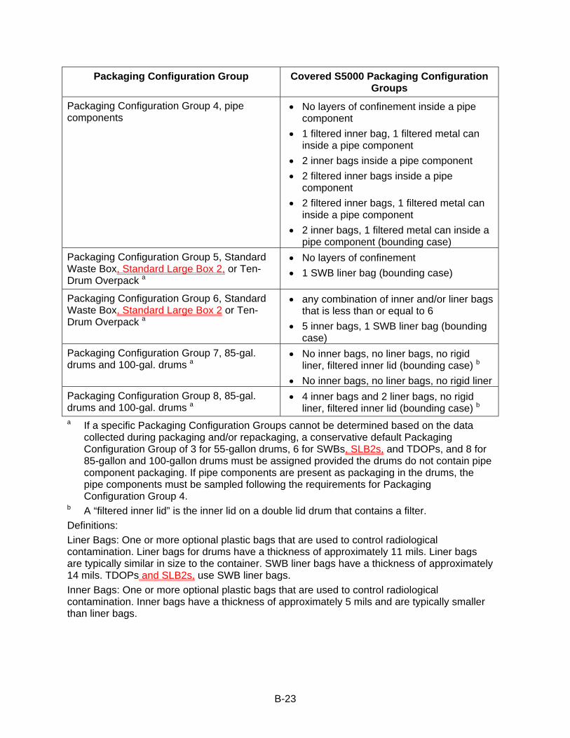
B-23
Packaging Configuration Group Covered S5000 Packaging Configuration Groups
Packaging Configuration Group 4, pipe components
• No layers of confinement inside a pipe component
• 1 filtered inner bag, 1 filtered metal can inside a pipe component
• 2 inner bags inside a pipe component • 2 filtered inner bags inside a pipe
component • 2 filtered inner bags, 1 filtered metal can
inside a pipe component • 2 inner bags, 1 filtered metal can inside a
pipe component (bounding case) Packaging Configuration Group 5, Standard Waste Box, Standard Large Box 2, or Ten-Drum Overpack a
• No layers of confinement • 1 SWB liner bag (bounding case)
Packaging Configuration Group 6, Standard Waste Box, Standard Large Box 2 or Ten-Drum Overpack a
• any combination of inner and/or liner bags that is less than or equal to 6
• 5 inner bags, 1 SWB liner bag (bounding case)
Packaging Configuration Group 7, 85-gal. drums and 100-gal. drums a
• No inner bags, no liner bags, no rigid liner, filtered inner lid (bounding case) b
• No inner bags, no liner bags, no rigid liner Packaging Configuration Group 8, 85-gal. drums and 100-gal. drums a
• 4 inner bags and 2 liner bags, no rigid liner, filtered inner lid (bounding case) b
a If a specific Packaging Configuration Groups cannot be determined based on the data collected during packaging and/or repackaging, a conservative default Packaging Configuration Group of 3 for 55-gallon drums, 6 for SWBs, SLB2s, and TDOPs, and 8 for 85-gallon and 100-gallon drums must be assigned provided the drums do not contain pipe component packaging. If pipe components are present as packaging in the drums, the pipe components must be sampled following the requirements for Packaging Configuration Group 4.
b A “filtered inner lid” is the inner lid on a double lid drum that contains a filter. Definitions: Liner Bags: One or more optional plastic bags that are used to control radiological contamination. Liner bags for drums have a thickness of approximately 11 mils. Liner bags are typically similar in size to the container. SWB liner bags have a thickness of approximately 14 mils. TDOPs and SLB2s, use SWB liner bags. Inner Bags: One or more optional plastic bags that are used to control radiological contamination. Inner bags have a thickness of approximately 5 mils and are typically smaller than liner bags.
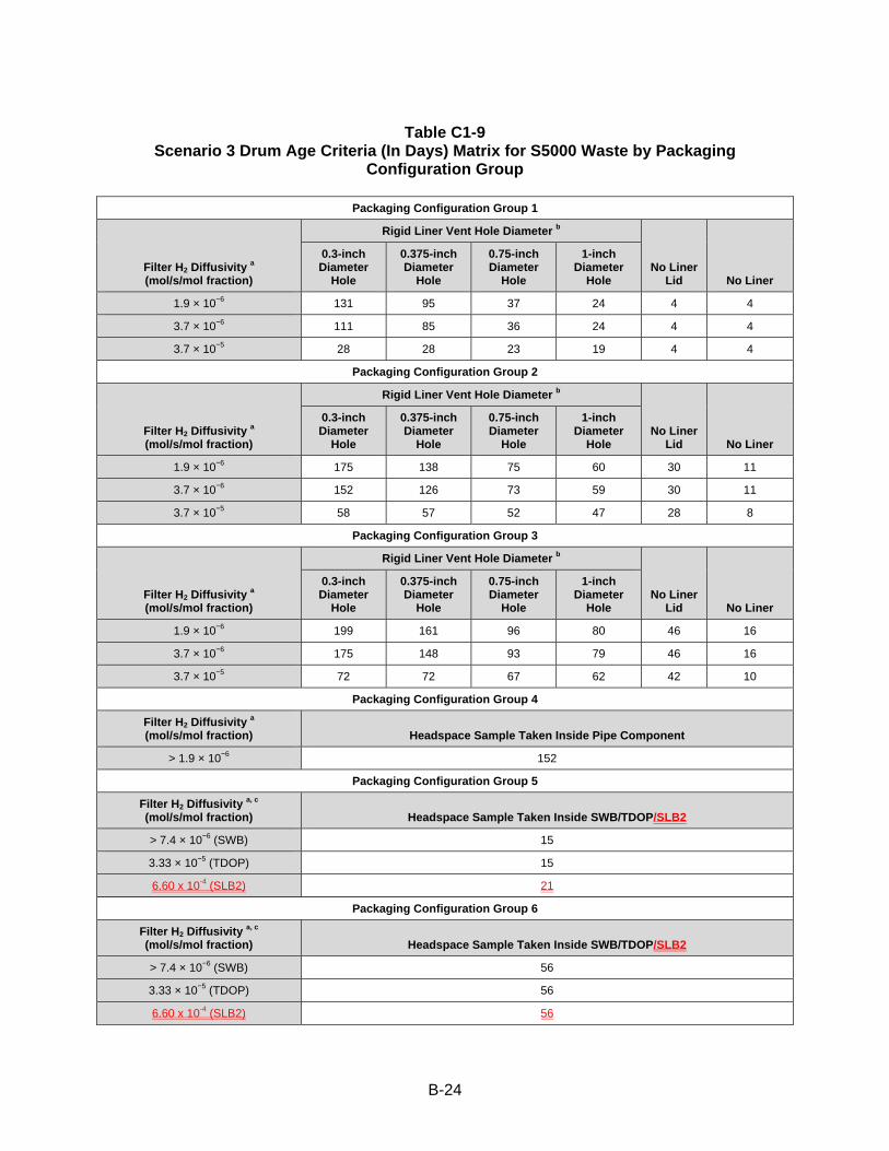
B-24
Table C1-9
Scenario 3 Drum Age Criteria (In Days) Matrix for S5000 Waste by Packaging Configuration Group
Packaging Configuration Group 1
Filter H2 Diffusivity a (mol/s/mol fraction)
Rigid Liner Vent Hole Diameter b
No Liner Lid No Liner
0.3-inch Diameter
Hole
0.375-inch Diameter
Hole
0.75-inch Diameter
Hole
1-inch Diameter
Hole
1.9 × 10⁻⁶ 131 95 37 24 4 4
3.7 × 10⁻⁶ 111 85 36 24 4 4
3.7 × 10⁻⁵ 28 28 23 19 4 4
Packaging Configuration Group 2
Filter H2 Diffusivity a (mol/s/mol fraction)
Rigid Liner Vent Hole Diameter b
No Liner Lid No Liner
0.3-inch Diameter
Hole
0.375-inch Diameter
Hole
0.75-inch Diameter
Hole
1-inch Diameter
Hole
1.9 × 10⁻⁶ 175 138 75 60 30 11
3.7 × 10⁻⁶ 152 126 73 59 30 11
3.7 × 10⁻⁵ 58 57 52 47 28 8
Packaging Configuration Group 3
Filter H2 Diffusivity a (mol/s/mol fraction)
Rigid Liner Vent Hole Diameter b
No Liner Lid No Liner
0.3-inch Diameter
Hole
0.375-inch Diameter
Hole
0.75-inch Diameter
Hole
1-inch Diameter
Hole
1.9 × 10⁻⁶ 199 161 96 80 46 16
3.7 × 10⁻⁶ 175 148 93 79 46 16
3.7 × 10⁻⁵ 72 72 67 62 42 10
Packaging Configuration Group 4
Filter H2 Diffusivity a (mol/s/mol fraction) Headspace Sample Taken Inside Pipe Component
> 1.9 × 10⁻⁶ 152
Packaging Configuration Group 5
Filter H2 Diffusivity a, c (mol/s/mol fraction) Headspace Sample Taken Inside SWB/TDOP/SLB2
> 7.4 × 10⁻⁶ (SWB) 15
3.33 × 10⁻⁵ (TDOP) 15
6.60 x 10⁻⁴ (SLB2) 21
Packaging Configuration Group 6
Filter H2 Diffusivity a, c (mol/s/mol fraction) Headspace Sample Taken Inside SWB/TDOP/SLB2
> 7.4 × 10⁻⁶ (SWB) 56
3.33 × 10⁻⁵ (TDOP) 56
6.60 x 10⁻⁴ (SLB2) 56
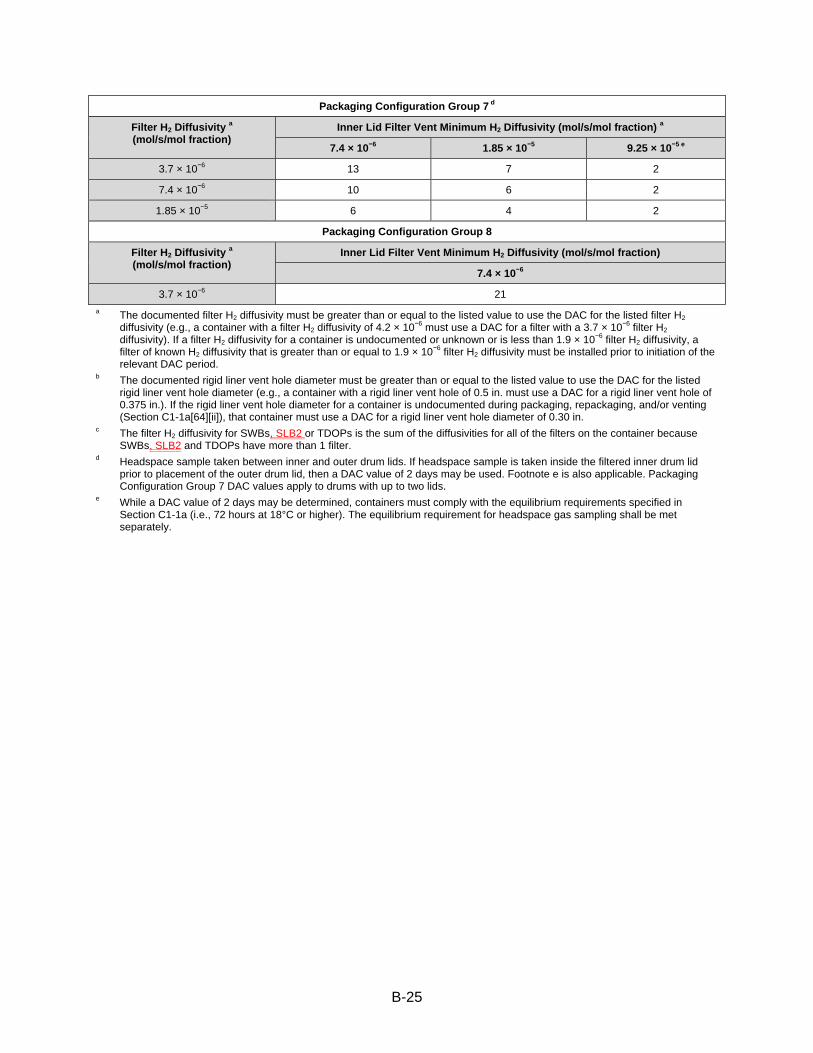
B-25
Packaging Configuration Group 7 d
Filter H2 Diffusivity a (mol/s/mol fraction)
Inner Lid Filter Vent Minimum H2 Diffusivity (mol/s/mol fraction) a
7.4 × 10⁻⁶ 1.85 × 10⁻⁵ 9.25 × 10⁻⁵ e
3.7 × 10⁻⁶ 13 7 2
7.4 × 10⁻⁶ 10 6 2
1.85 × 10⁻⁵ 6 4 2
Packaging Configuration Group 8
Filter H2 Diffusivity a (mol/s/mol fraction)
Inner Lid Filter Vent Minimum H2 Diffusivity (mol/s/mol fraction)
7.4 × 10⁻⁶
3.7 × 10⁻⁶ 21 a The documented filter H2 diffusivity must be greater than or equal to the listed value to use the DAC for the listed filter H2
diffusivity (e.g., a container with a filter H2 diffusivity of 4.2 × 10⁻⁶ must use a DAC for a filter with a 3.7 × 10⁻⁶ filter H2 diffusivity). If a filter H2 diffusivity for a container is undocumented or unknown or is less than 1.9 × 10⁻⁶ filter H2 diffusivity, a filter of known H2 diffusivity that is greater than or equal to 1.9 × 10⁻⁶ filter H2 diffusivity must be installed prior to initiation of the relevant DAC period.
b The documented rigid liner vent hole diameter must be greater than or equal to the listed value to use the DAC for the listed rigid liner vent hole diameter (e.g., a container with a rigid liner vent hole of 0.5 in. must use a DAC for a rigid liner vent hole of 0.375 in.). If the rigid liner vent hole diameter for a container is undocumented during packaging, repackaging, and/or venting (Section C1-1a[64][ii]), that container must use a DAC for a rigid liner vent hole diameter of 0.30 in.
c The filter H2 diffusivity for SWBs, SLB2 or TDOPs is the sum of the diffusivities for all of the filters on the container because SWBs, SLB2 and TDOPs have more than 1 filter.
d Headspace sample taken between inner and outer drum lids. If headspace sample is taken inside the filtered inner drum lid prior to placement of the outer drum lid, then a DAC value of 2 days may be used. Footnote e is also applicable. Packaging Configuration Group 7 DAC values apply to drums with up to two lids.
e While a DAC value of 2 days may be determined, containers must comply with the equilibrium requirements specified in Section C1-1a (i.e., 72 hours at 18°C or higher). The equilibrium requirement for headspace gas sampling shall be met separately.

B-26
D-1d Description of Containers CH TRU mixed waste containers will be either 55-gallon (gal) (208-liter (L)) drums singly or arranged into seven (7)-packs, 85-gal (322-L) drums (used as singly or arranged into four (4)-packs, 100-gal (379 L) drums singly or arranged into three (3)-packs, ten-drum overpacks (TDOP), standard large box 2s (SLB2) or 66 ft3 (1.88 m3) SWBs.
RH TRU mixed waste containers are either canisters or drums. Canisters will be loaded singly in an RH-TRU 72-B cask and drums will be loaded in a CNS 10-160B cask. Drums in the CNS 10-160B cask will be arranged singly or in drum carriage units containing up to five drums each. Canisters and drums are described in Permit Attachment M1.
D-1e Description of Surface Hazardous Waste Management Units The WHB is the surface facility where waste handling activities will take place. The WHB has a total area of approximately 84,000 square feet (ft2) (7,804 square meters [m2]) of which 43,554 49,710 ft2 (4,047 4,618 m2) are designated as the WHB Unit for TRU mixed waste management. Within the WHB Unit, 26,151 32,307 ft2 (2,430 3,001 m2) are designated for the waste handling and container storage of CH TRU mixed waste and 17,403 ft2 (1,617 m2) are designated for the handling and storage of RH TRU mixed waste. These areas are being permitted as container storage units. The concrete floors within the WHB Unit are sealed with an impermeable coating that has excellent resistance to the chemicals in TRU mixed waste and, consequently, provide secondary containment for TRU mixed waste. In addition, a Parking Area Unit south of the WHB will be used for storage of waste in sealed shipping containers awaiting unloading. This area is also being permitted as a container storage unit. The sealed shipping containers provide secondary containment in this hazardous waste management unit (HWMU). D-1e(1) CH Bay Operations Once unloaded from the Contact-Handled Package, CH TRU mixed waste containers (7-packs of 55-gal drums, 3-packs of 100-gal drums, 4-packs of 85-gal drums, SWBs, one SLB2, or TDOPs) are placed in one of two positions on the facility pallet. The waste containers are stacked on the facility pallets (one- or two-high, depending on weight considerations). The use of facility pallets will elevate the waste at least 6 inches (in.) (15 centimeters [cm]) from the floor surface. Pallets of waste will then be stored in the CH bay. This storage area will be clearly marked to indicate the lateral limits of the storage area. This storage area will have a maximum capacity of thirteen facility pallets of waste during normal operations. These pallets will typically be in the CH Bay storage area for a period of up to five days.
D-4d(6) Control of Spills or Leaking or Punctured Containers of CH and RH TRU Mixed Waste In the event of spills or leaking or punctured containers of CH and RH TRU mixed waste, the WIPP responds to three distinct phases: 1) the event, 2) the re-entry, and 3) the recovery. During the event, the following immediate actions are completed: 1) stop work, 2) warn others (notify CMR), 3) isolate the area, 4) minimize exposure, and 5) close off unfiltered ventilation. These actions can take place simultaneously, as long as they are completed before proceeding to the re-entry phase.
B-27
CH TRU Mixed Waste
Should a breach of a CH TRU mixed waste container occur at the WIPP that results in removable contamination exceeding the small area “spot” decontamination levels, the affected container(s) (e.g., breached and contaminated) will be placed into an available overpack container (e.g., 85-gal drum, SWB, TDOP), except that TDOPs and SLB2s will be decontaminated, repaired/patched in accordance with 49 CFR §173 and §178 (e.g., 49 CFR §173.28), or returned to the generator. The decontamination of equipment and the overpacking of contaminated/damaged waste containers will be performed in the vicinity of the incident. For example, under normal operations CH TRU mixed waste will be handled only in the areas of the WHB Unit. Therefore, it is within these same areas that decontamination and/or overpacking operations would occur. By eliminating the transport of contaminated equipment to other areas for decontamination or overpacking, the risk of spreading contamination is reduced.

B-28
E-1b(1) Container Inspection Containers are used to manage TRU mixed waste at the WIPP facility. These containers are described in Permit Part 3Module III. Off-site CH TRU mixed waste will arrive in 55-gallon drums arranged as seven (7)-packs, in Ten Drum Overpacks (TDOP), in 85-gallon drums arranged as four (4) packs, in 100-gallon drums arranged as three (3) packs, in standard large box 2s (SLB2), or in standard waste boxes (SWB). The waste containers will be visually inspected to ensure that the waste containers are in good condition and that there are no signs that a release has occurred. This visual inspection shall not include the center drums of 7-packs and waste containers positioned such that visual observation is precluded due to the arrangement of waste assemblies on the facility pallets. If CH TRU mixed waste handling operations should stop for any reason with containers located on the TRUPACT-II Unloading Dock (TRUDOCK storage area of the WHB Unit) or in Room 108 while still in the Contact-Handled Packages, primary waste container inspections could not be accomplished until the containers of waste are removed from the shipping containers.
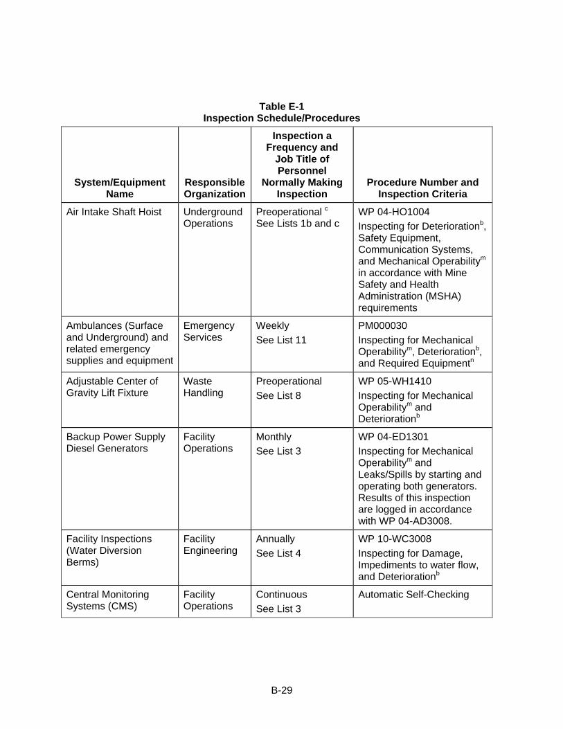
B-29
Table E-1 Inspection Schedule/Procedures
System/Equipment Name
Responsible Organization
Inspection a Frequency and
Job Title of Personnel
Normally Making Inspection
Procedure Number and Inspection Criteria
Air Intake Shaft Hoist Underground Operations
Preoperational c See Lists 1b and c
WP 04-HO1004 Inspecting for Deteriorationb, Safety Equipment, Communication Systems, and Mechanical Operabilitym in accordance with Mine Safety and Health Administration (MSHA) requirements
Ambulances (Surface and Underground) and related emergency supplies and equipment
Emergency Services
Weekly See List 11
PM000030 Inspecting for Mechanical Operabilitym, Deteriorationb, and Required Equipmentn
Adjustable Center of Gravity Lift Fixture
Waste Handling
Preoperational See List 8
WP 05-WH1410 Inspecting for Mechanical Operabilitym and Deteriorationb
Backup Power Supply Diesel Generators
Facility Operations
Monthly See List 3
WP 04-ED1301 Inspecting for Mechanical Operabilitym and Leaks/Spills by starting and operating both generators. Results of this inspection are logged in accordance with WP 04-AD3008.
Facility Inspections (Water Diversion Berms)
Facility Engineering
Annually See List 4
WP 10-WC3008 Inspecting for Damage, Impediments to water flow, and Deteriorationb
Central Monitoring Systems (CMS)
Facility Operations
Continuous See List 3
Automatic Self-Checking
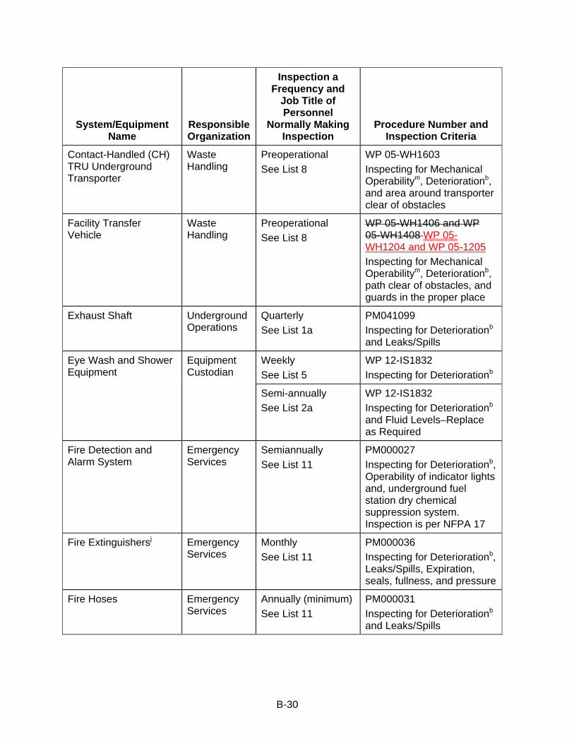
B-30
System/Equipment Name
Responsible Organization
Inspection a Frequency and
Job Title of Personnel
Normally Making Inspection
Procedure Number and Inspection Criteria
Contact-Handled (CH) TRU Underground Transporter
Waste Handling
Preoperational See List 8
WP 05-WH1603 Inspecting for Mechanical Operabilitym, Deteriorationb, and area around transporter clear of obstacles
Facility Transfer Vehicle
Waste Handling
Preoperational See List 8
WP 05-WH1406 and WP 05-WH1408 WP 05-WH1204 and WP 05-1205 Inspecting for Mechanical Operabilitym, Deteriorationb, path clear of obstacles, and guards in the proper place
Exhaust Shaft Underground Operations
Quarterly See List 1a
PM041099 Inspecting for Deteriorationb and Leaks/Spills
Eye Wash and Shower Equipment
Equipment Custodian
Weekly See List 5
WP 12-IS1832 Inspecting for Deteriorationb
Semi-annually See List 2a
WP 12-IS1832 Inspecting for Deteriorationb and Fluid Levels–Replace as Required
Fire Detection and Alarm System
Emergency Services
Semiannually See List 11
PM000027 Inspecting for Deteriorationb, Operability of indicator lights and, underground fuel station dry chemical suppression system. Inspection is per NFPA 17
Fire Extinguishersj Emergency Services
Monthly See List 11
PM000036 Inspecting for Deteriorationb, Leaks/Spills, Expiration, seals, fullness, and pressure
Fire Hoses Emergency Services
Annually (minimum) See List 11
PM000031 Inspecting for Deteriorationb and Leaks/Spills
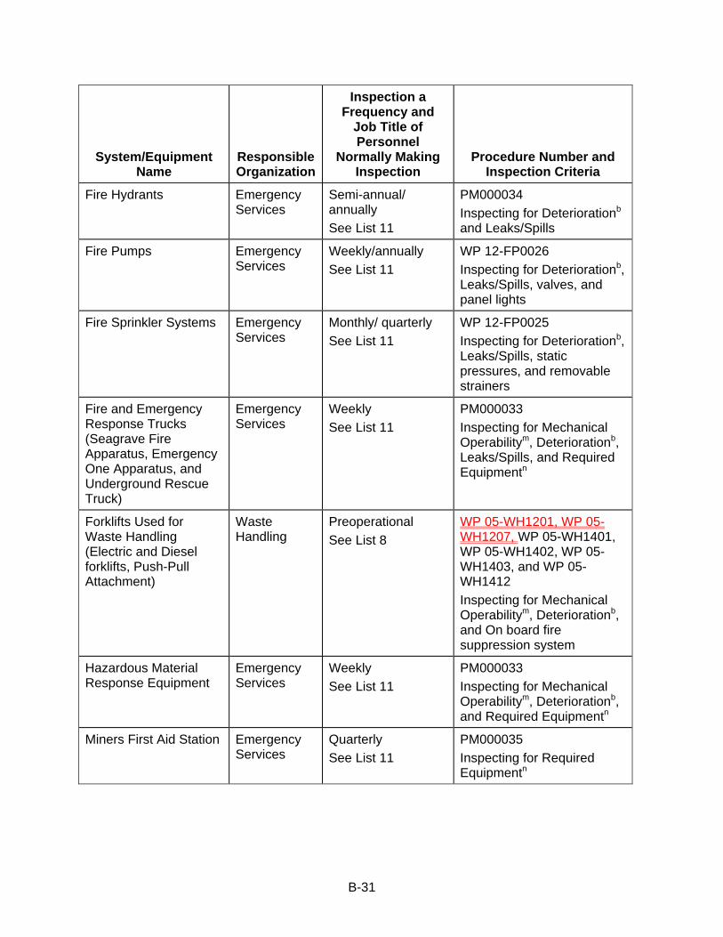
B-31
System/Equipment Name
Responsible Organization
Inspection a Frequency and
Job Title of Personnel
Normally Making Inspection
Procedure Number and Inspection Criteria
Fire Hydrants Emergency Services
Semi-annual/ annually See List 11
PM000034 Inspecting for Deteriorationb and Leaks/Spills
Fire Pumps Emergency Services
Weekly/annually See List 11
WP 12-FP0026 Inspecting for Deteriorationb, Leaks/Spills, valves, and panel lights
Fire Sprinkler Systems Emergency Services
Monthly/ quarterly See List 11
WP 12-FP0025 Inspecting for Deteriorationb, Leaks/Spills, static pressures, and removable strainers
Fire and Emergency Response Trucks (Seagrave Fire Apparatus, Emergency One Apparatus, and Underground Rescue Truck)
Emergency Services
Weekly See List 11
PM000033 Inspecting for Mechanical Operabilitym, Deteriorationb, Leaks/Spills, and Required Equipmentn
Forklifts Used for Waste Handling (Electric and Diesel forklifts, Push-Pull Attachment)
Waste Handling
Preoperational See List 8
WP 05-WH1201, WP 05-WH1207, WP 05-WH1401, WP 05-WH1402, WP 05-WH1403, and WP 05-WH1412 Inspecting for Mechanical Operabilitym, Deteriorationb, and On board fire suppression system
Hazardous Material Response Equipment
Emergency Services
Weekly See List 11
PM000033 Inspecting for Mechanical Operabilitym, Deteriorationb, and Required Equipmentn
Miners First Aid Station Emergency Services
Quarterly See List 11
PM000035 Inspecting for Required Equipmentn

B-32
System/Equipment Name
Responsible Organization
Inspection a Frequency and
Job Title of Personnel
Normally Making Inspection
Procedure Number and Inspection Criteria
Mine Pager Phones (between surface and underground)
Facility Operations
Monthly See List 3
WP 04-PC3017 Testing of PA and Underground Alarms and Mine Page Phones at essential locations
MSHA Air Quality Monitor
Maintenance/ Underground Operations
Dailyl See Lists 1 and 10
WP 12-IH1828 Inspecting for Air Quality Monitoring Equipment Functional Check
Perimeter Fence, Gates, Signs
Security Daily See List 6
PF0-008 Inspecting for Deteriorationb and Posted Warnings
Personal Protective Equipment (not otherwise contained in emergency vehicles or issued to individuals): —Self-Contained Breathing Apparatus
Emergency Services
Weekly See List 11
PM000029 Inspecting for Deteriorationb and Pressure
Public Address (and Intercom System)
Facility Operations
Monthly See List 3
WP 04-PC3017 Testing of PA and Underground Alarms and Mine Page Phones at essential locations Systems operated in test mode
Radio Equipment Facility Operations
Dailyi See List 3
Radios are operated daily and are repaired upon failure
Rescue Truck (Surface and Underground)
Emergency Services
Weekly See List 11
PM000030 and PM000033 Inspecting for Mechanical Operabilitym, Deteriorationb, Leaks/Spills, and Required Equipmentn
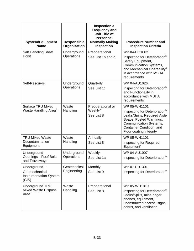
B-33
System/Equipment Name
Responsible Organization
Inspection a Frequency and
Job Title of Personnel
Normally Making Inspection
Procedure Number and Inspection Criteria
Salt Handling Shaft Hoist
Underground Operations
Preoperational See List 1b and c
WP 04-HO1002 Inspecting for Deteriorationb, Safety Equipment, Communication Systems, and Mechanical Operabilitym in accordance with MSHA requirements
Self-Rescuers Underground Operations
Quarterly See List 1c
WP 04-AU1026 Inspecting for Deteriorationb and Functionality in accordance with MSHA requirements
Surface TRU Mixed Waste Handling Area k
Waste Handling
Preoperational or Weekly e See List 8
WP 05-WH1101 Inspecting for Deteriorationb, Leaks/Spills, Required Aisle Space, Posted Warnings, Communication Systems, Container Condition, and Floor coating integrity
TRU Mixed Waste Decontamination Equipment
Waste Handling
Annually See List 8
WP 05-WH1101 Inspecting for Required Equipmentn
Underground Openings—Roof Bolts and Travelways
Underground Operations
Weekly See List 1a
WP 04-AU1007 Inspecting for Deteriorationb
Underground— Geomechanical Instrumentation System (GIS)
Geotechnical Engineering
Monthly See List 9
WP 07-EU1301 Inspecting for Deteriorationb
Underground TRU Mixed Waste Disposal Area
Waste Handling
Preoperational See List 8
WP 05-WH1810 Inspecting for Deteriorationb, Leaks/Spills, mine pager phones, equipment, unobstructed access, signs, debris, and ventilation
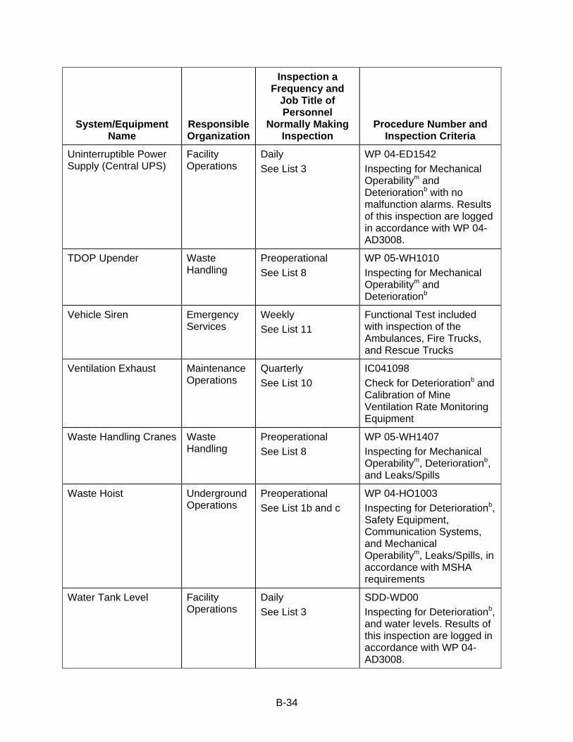
B-34
System/Equipment Name
Responsible Organization
Inspection a Frequency and
Job Title of Personnel
Normally Making Inspection
Procedure Number and Inspection Criteria
Uninterruptible Power Supply (Central UPS)
Facility Operations
Daily See List 3
WP 04-ED1542 Inspecting for Mechanical Operabilitym and Deteriorationb with no malfunction alarms. Results of this inspection are logged in accordance with WP 04-AD3008.
TDOP Upender Waste Handling
Preoperational See List 8
WP 05-WH1010 Inspecting for Mechanical Operabilitym and Deteriorationb
Vehicle Siren Emergency Services
Weekly See List 11
Functional Test included with inspection of the Ambulances, Fire Trucks, and Rescue Trucks
Ventilation Exhaust Maintenance Operations
Quarterly See List 10
IC041098 Check for Deteriorationb and Calibration of Mine Ventilation Rate Monitoring Equipment
Waste Handling Cranes Waste Handling
Preoperational See List 8
WP 05-WH1407 Inspecting for Mechanical Operabilitym, Deteriorationb, and Leaks/Spills
Waste Hoist Underground Operations
Preoperational See List 1b and c
WP 04-HO1003 Inspecting for Deteriorationb, Safety Equipment, Communication Systems, and Mechanical Operabilitym, Leaks/Spills, in accordance with MSHA requirements
Water Tank Level Facility Operations
Daily See List 3
SDD-WD00 Inspecting for Deteriorationb, and water levels. Results of this inspection are logged in accordance with WP 04-AD3008.
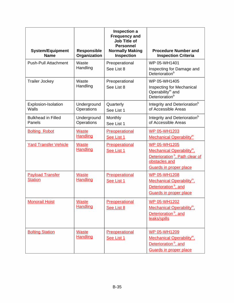
B-35
System/Equipment Name
Responsible Organization
Inspection a Frequency and
Job Title of Personnel
Normally Making Inspection
Procedure Number and Inspection Criteria
Push-Pull Attachment Waste Handling
Preoperational See List 8
WP 05-WH1401 Inspecting for Damage and Deteriorationb
Trailer Jockey Waste Handling
Preoperational See List 8
WP 05-WH1405 Inspecting for Mechanical Operabilitym and Deteriorationb
Explosion-Isolation Walls
Underground Operations
Quarterly See List 1
Integrity and Deteriorationb of Accessible Areas
Bulkhead in Filled Panels
Underground Operations
Monthly See List 1
Integrity and Deteriorationb of Accessible Areas
Bolting Robot Waste Handling
Preoperational See List 1
WP 05-WH1203 Mechanical Operabilitym
Yard Transfer Vehicle Waste Handling
Preoperational See List 1
WP 05-WH1205 Mechanical Operabilitym, Deterioration b, Path clear of obstacles and Guards in proper place
Payload Transfer Station
Waste Handling
Preoperational See List 1
WP 05-WH1208 Mechanical Operabilitym, Deterioration b, and Guards in proper place
Monorail Hoist Waste Handling
Preoperational See List 8
WP 05-WH1202 Mechanical Operabilitym, Deterioration b, and leaks/spills
Bolting Station Waste Handling
Preoperational See List 1
WP 05-WH1209 Mechanical Operabilitym, Deterioration b, and Guards in proper place
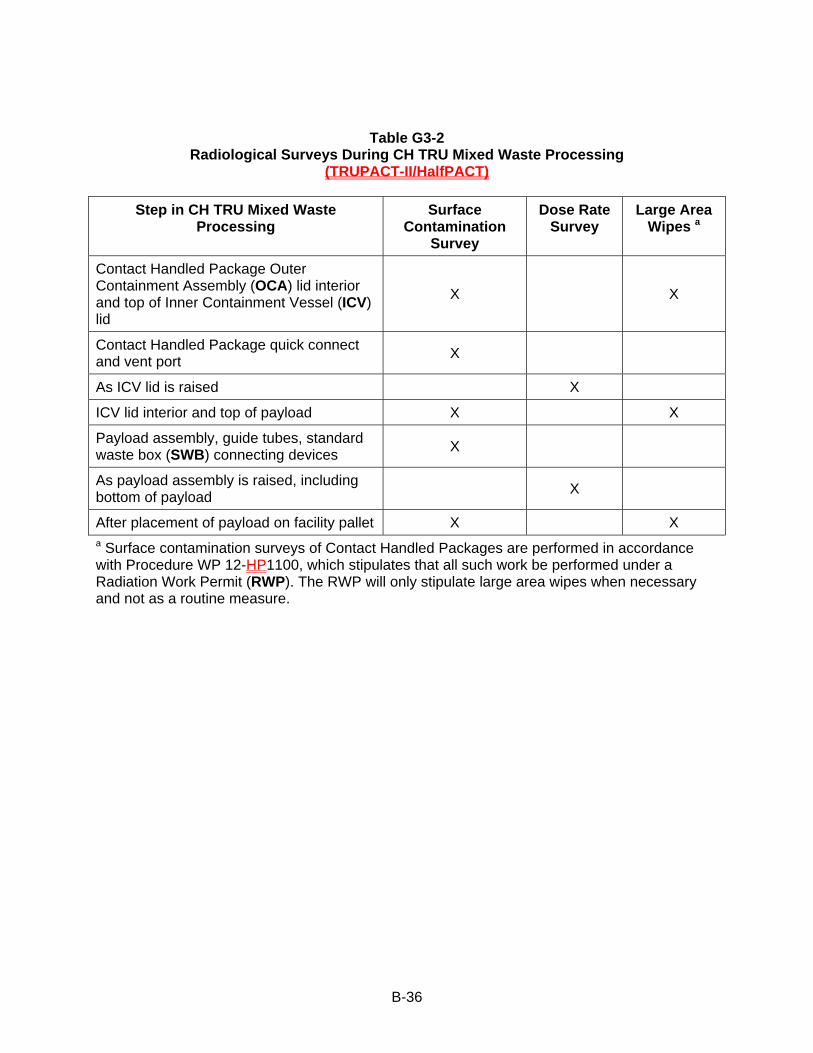
B-36
Table G3-2 Radiological Surveys During CH TRU Mixed Waste Processing
(TRUPACT-II/HalfPACT)
Step in CH TRU Mixed Waste Processing
Surface Contamination
Survey
Dose Rate Survey
Large Area Wipes a
Contact Handled Package Outer Containment Assembly (OCA) lid interior and top of Inner Containment Vessel (ICV) lid
X X
Contact Handled Package quick connect and vent port X
As ICV lid is raised X
ICV lid interior and top of payload X X
Payload assembly, guide tubes, standard waste box (SWB) connecting devices X
As payload assembly is raised, including bottom of payload X
After placement of payload on facility pallet X X a Surface contamination surveys of Contact Handled Packages are performed in accordance with Procedure WP 12-HP1100, which stipulates that all such work be performed under a Radiation Work Permit (RWP). The RWP will only stipulate large area wipes when necessary and not as a routine measure.

B-37
Table G3-2a
Radiological Surveys During CH TRU Mixed Waste Processing for TRUPACT-III
Steps in CH TRU Mixed Waste Processing
Surface Contamination
Survey
Dose Rate Survey
Large Area Wipesa
Exterior of TRUPACT-III on arrival at WIPP
X
X
Interior of Overpack Cover and exterior of Containment Lid
X
X X
TRUPACT-III Vent Port Tool Assembly quick connect
X
Interior of Containment Lid and front of SLB2
X
X X
As SLB2 is removed from TRUPACT-III
X
After placement of SLB2 on facility pallet
X
X
a Surface contamination surveys of Contact Handled Packages are performed in accordance with Procedure WP 12-HP1100, which stipulates that all such work be performed under a Radiation Work Permit (RWP). The RWP will only stipulate large area wipes when necessary and not as a routine measure.
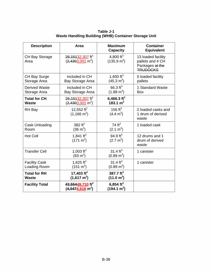
B-38
Table J-1
Waste Handling Building (WHB) Container Storage Unit
Description Area Maximum Capacity
Container Equivalent
CH Bay Storage Area
26,15132,307 ft2
(2,4303,001 m2) 4,800 ft3
(135.9 m3) 13 loaded facility pallets and 4 CH Packages at the TRUDOCKS
CH Bay Surge Storage Area
included in CH Bay Storage Area
1,600 ft3 (45.3 m3)
5 loaded facility pallets
Derived Waste Storage Area
included in CH Bay Storage Area
66.3 ft3 (1.88 m3)
1 Standard Waste Box
Total for CH Waste
26,15132,307 ft2 (2,4303,001 m2)
6,466.3 ft3 183.1 m3
RH Bay 12,552 ft2 (1,166 m2)
156 ft3 (4.4 m3)
2 loaded casks and 1 drum of derived waste
Cask Unloading Room
382 ft2 (36 m2)
74 ft3 (2.1 m3)
1 loaded cask
Hot Cell 1,841 ft2 (171 m2)
94.9 ft3 (2.7 m3)
12 drums and 1 drum of derived waste
Transfer Cell 1,003 ft2 (93 m2)
31.4 ft3 (0.89 m3)
1 canister
Facility Cask Loading Room
1,625 ft2 (151 m2)
31.4 ft3 (0.89 m3)
1 canister
Total for RH Waste
17,403 ft2 (1,617 m2)
387.7 ft3 (11.0 m3)
Facility Total 43,55449,710 ft2 (4,0474,618 m2)
6,854 ft3 (194.1 m3)
Attachment C Drum Age Criteria Values for the Standard Large Box 2 (SLB2)

AL/12-10/WP/WTS:SLB2 DAC Report-Rev 2 Dec 2010.docx
DDRRUUMM AAGGEE CCRRIITTEERRIIAA VVAALLUUEESS FFOORR TTHHEE SSTTAANNDDAARRDD LLAARRGGEE BBOOXX 22 ((SSLLBB22))
DDeecceemmbbeerr 22001100
RReevviissiioonn 22
Prepared for: Washington TRU Solutions, LLC PO Box 2078 4021 National Parks Highway Carlsbad, New Mexico 88221 Prepared by: Shaw Environmental, Inc. 2440 Louisiana Blvd. NE Suite 300 Albuquerque, New Mexico 87110
AL/12-10/WP/WTS:SLB2 DAC Report-Rev 2 Dec 2010.docx 136082.02000000 12/28/10 4:41 PM i
Table of Contents ________________________________________________
List of Appendices .......................................................................................................................................... i Acronyms, Abbreviations, and Units ............................................................................................................... ii 1.0 Background and Purpose .................................................................................................................. 1 2.0 Methodology ...................................................................................................................................... 2
2.1 Packaging Configuration ......................................................................................................... 2 2.2 Model Parameter Definitions ................................................................................................... 2
3.0 Results ............................................................................................................................................... 4
4.0 References ........................................................................................................................................ 4
List of Appendices _______________________________________________
Appendix A Input and Output Files Associated with the Standard Large Box 2 DAC Determination

AL/12-10/WP/WTS:SLB2 DAC Report-Rev 2 Dec 2010.docx 136082.02000000 12/28/10 4:41 PM ii
Acronyms, Abbreviations, and Units ________________________________
atm atmosphere CH-TRU contact-handled transuranic DAC drum age criterion K Kelvin mol/s/mf mole/second/mole fraction SLB2 Standard Large Box 2 TRU transuranic VOC volatile organic compound
AL/12-10/WP/WTS:SLB2 DAC Report-Rev 2 Dec 2010.docx 136082.02000000 12/28/10 4:41 PM 1
1.0 Background and Purpose ____________________________________
Containers of transuranic (TRU) waste must meet a minimum age criterion before a volatile organic compound (VOC) gas sample collected from the waste container headspace is considered representative of the VOC gas within the container headspace. The drum age criterion (DAC) is the time required after container closure, or after container closure and container venting, before a representative headspace gas sample can be collected. The methodology described in “Determination of Drum Age Criteria and Prediction Factors Based on Packaging Configurations” (BWXT, 2000) is the basis for the packaging-specific DAC values currently approved in the Hazardous Waste Facility Permit for the Waste Isolation Pilot Plant (WIPP) (“Permit”) (NMED, Current Version).
The TRUPACT-III packaging has been licensed by the U.S. Nuclear Regulatory Commission for the transport of CH-TRU waste. The only authorized payload container for the TRUPACT-III is the Standard Large Box 2 (SLB2). The TRUPACT-III will accommodate one SLB2. The SLB2 has been specifically designed for efficient loading of the TRUPACT-III. The SLB2 is vented with one or more filter vents meeting a minimum total hydrogen diffusivity value of 6.60E-4 mole per second per mole fraction (mol/s/mf).
Packaging-specific DAC values were previously determined for a number of CH-TRU packaging configurations (BWXT, 2000; Shaw, 2003). The DAC for each packaging configuration was determined using the computer program VDRUM that solved a series of differential equations describing the VOC transport phenomena within the waste container (BWXT, 2000; Connolly et al., 1998). Model input parameters include the physical properties of VOCs, the initial concentration profile in the waste container, physical dimensions of each confinement layer (thickness, surface area, void volume), and the hydrogen diffusion characteristics of filter vents installed on the waste containers (BWXT, 2000; Connolly et al., 1998). Model parameters and assumptions used in determining the DAC values have also been documented (Shaw, 2003; BWXT, 2000; Connolly et al., 1998).
The purpose of this report is to document packaging-specific DAC values for SLB2 packaging configurations as determined using the BWXT (2000) methodology. The application of the BWXT (2000) methodology to the SLB2 is consistent with the direction provided by Section B1-1a (3) of Attachment B1 of the Permit (NMED, Current Version), which requires the following: “If additional packaging configurations are identified, an appropriate Permit Modification will be submitted to incorporate the DAC using the methodology in BWXT (2000).” Model parameters and assumptions used in determining the DAC values are also documented in this report.

AL/12-10/WP/WTS:SLB2 DAC Report-Rev 2 Dec 2010.docx 136082.02000000 12/28/10 4:41 PM 2
2.0 Methodology _______________________________________________
The BWXT (2000) and Shaw (2003) reports document all parameters and assumptions used in previous DAC calculations. Parameter values specific to the SLB2 evaluations are discussed below and are listed in the input files included in Appendix A. Additional assumptions used in determining the DAC values for the SLB2 are presented in this section.
2.1 Packaging Configuration
The SLB2 packaging configurations analyzed consist of (1) up to one liner bag and (2) up to six bag layers total, up to one of which may be a liner bag. These packaging configurations are consistent with those defined for the standard waste box (SWB) and the ten-drum overpack (TDOP) as Packaging Configuration Groups 5 and 6 in Table B1-8 of Attachment B1 of the Permit (NMED, Current Version). The inner bags are each five mils (0.013 centimeter [cm]) thick and the liner bag is 14 mils (0.036 cm) thick (same thickness as an SWB liner bag). The SLB2 is vented with one or more filter vents meeting a minimum total hydrogen diffusivity value of 6.60E-4 mol/s/mf. Other parameter values are documented below and in Appendix A.
2.2 Model Parameter Definitions
Permeable Surface Area
When liner bags are used to package waste items in the SLB2, multiple bags are loaded into the SLB2 in parallel due to the large size of the SLB2 payload container size. As a result, the combined surface area of the multiple bags can be modeled with an assumed total permeable surface area that includes a surface area corresponding to the cross-sectional area of the SLB2 payload container as well as the horizontal surface areas between the top of the waste and the base of the SLB2 payload container. The surface area of the bottom of the liner bag that is sitting on the floor of the SLB2 is not considered to be permeable.
The internal dimensions of the SLB2 are as follows:
Height = 66.5 in. (168.9 cm) Length = 104.25 in. (264.8 cm) Width = 65.25 in. (165.7 cm)
Allowing for 2.0 cm space between the liner bag and the SLB2 container wall on the top and sides, the total permeable surface area of the liner bag is calculated as:
Total Permeable Surface Area = (260.8 cm)(161.7 cm) + 2(260.8 cm)(166.9 cm) + 2(161.7 cm)(166.9 cm) = 183,202 cm2 ≈ 1.832E5 cm2
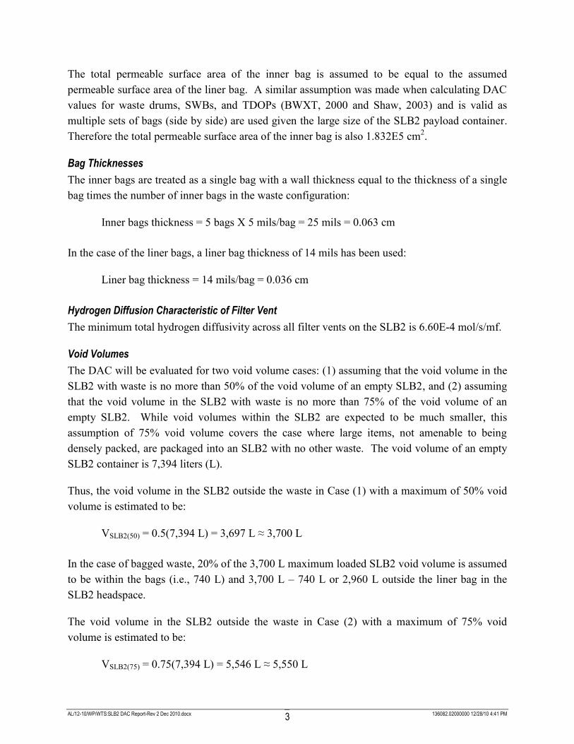
AL/12-10/WP/WTS:SLB2 DAC Report-Rev 2 Dec 2010.docx 136082.02000000 12/28/10 4:41 PM 3
The total permeable surface area of the inner bag is assumed to be equal to the assumed permeable surface area of the liner bag. A similar assumption was made when calculating DAC values for waste drums, SWBs, and TDOPs (BWXT, 2000 and Shaw, 2003) and is valid as multiple sets of bags (side by side) are used given the large size of the SLB2 payload container. Therefore the total permeable surface area of the inner bag is also 1.832E5 cm2.
Bag Thicknesses
The inner bags are treated as a single bag with a wall thickness equal to the thickness of a single bag times the number of inner bags in the waste configuration:
Inner bags thickness = 5 bags X 5 mils/bag = 25 mils = 0.063 cm
In the case of the liner bags, a liner bag thickness of 14 mils has been used:
Liner bag thickness = 14 mils/bag = 0.036 cm
Hydrogen Diffusion Characteristic of Filter Vent
The minimum total hydrogen diffusivity across all filter vents on the SLB2 is 6.60E-4 mol/s/mf.
Void Volumes
The DAC will be evaluated for two void volume cases: (1) assuming that the void volume in the SLB2 with waste is no more than 50% of the void volume of an empty SLB2, and (2) assuming that the void volume in the SLB2 with waste is no more than 75% of the void volume of an empty SLB2. While void volumes within the SLB2 are expected to be much smaller, this assumption of 75% void volume covers the case where large items, not amenable to being densely packed, are packaged into an SLB2 with no other waste. The void volume of an empty SLB2 container is 7,394 liters (L).
Thus, the void volume in the SLB2 outside the waste in Case (1) with a maximum of 50% void volume is estimated to be:
VSLB2(50) = 0.5(7,394 L) = 3,697 L ≈ 3,700 L
In the case of bagged waste, 20% of the 3,700 L maximum loaded SLB2 void volume is assumed to be within the bags (i.e., 740 L) and 3,700 L – 740 L or 2,960 L outside the liner bag in the SLB2 headspace.
The void volume in the SLB2 outside the waste in Case (2) with a maximum of 75% void volume is estimated to be:
VSLB2(75) = 0.75(7,394 L) = 5,546 L ≈ 5,550 L
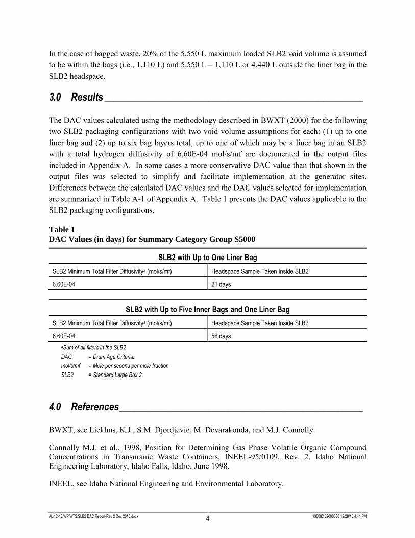
AL/12-10/WP/WTS:SLB2 DAC Report-Rev 2 Dec 2010.docx 136082.02000000 12/28/10 4:41 PM 4
In the case of bagged waste, 20% of the 5,550 L maximum loaded SLB2 void volume is assumed to be within the bags (i.e., 1,110 L) and 5,550 L – 1,110 L or 4,440 L outside the liner bag in the SLB2 headspace.
3.0 Results ____________________________________________________
The DAC values calculated using the methodology described in BWXT (2000) for the following two SLB2 packaging configurations with two void volume assumptions for each: (1) up to one liner bag and (2) up to six bag layers total, up to one of which may be a liner bag in an SLB2 with a total hydrogen diffusivity of 6.60E-04 mol/s/mf are documented in the output files included in Appendix A. In some cases a more conservative DAC value than that shown in the output files was selected to simplify and facilitate implementation at the generator sites. Differences between the calculated DAC values and the DAC values selected for implementation are summarized in Table A-1 of Appendix A. Table 1 presents the DAC values applicable to the SLB2 packaging configurations.
Table 1 DAC Values (in days) for Summary Category Group S5000
SLB2 with Up to One Liner Bag
SLB2 Minimum Total Filter Diffusivitya (mol/s/mf) Headspace Sample Taken Inside SLB2
6.60E-04 21 days
SLB2 with Up to Five Inner Bags and One Liner Bag
SLB2 Minimum Total Filter Diffusivitya (mol/s/mf) Headspace Sample Taken Inside SLB2
6.60E-04 56 days
aSum of all filters in the SLB2
DAC = Drum Age Criteria.
mol/s/mf = Mole per second per mole fraction.
SLB2 = Standard Large Box 2.
4.0 References _________________________________________________
BWXT, see Liekhus, K.J., S.M. Djordjevic, M. Devarakonda, and M.J. Connolly.
Connolly M.J. et al., 1998, Position for Determining Gas Phase Volatile Organic Compound Concentrations in Transuranic Waste Containers, INEEL-95/0109, Rev. 2, Idaho National Engineering Laboratory, Idaho Falls, Idaho, June 1998.
INEEL, see Idaho National Engineering and Environmental Laboratory.
AL/12-10/WP/WTS:SLB2 DAC Report-Rev 2 Dec 2010.docx 136082.02000000 12/28/10 4:41 PM 5
Liekhus, K.J., S.M. Djordjevic, M. Devarakonda, and M.J. Connolly (BWXT), 2000, Determination of Drum Age Criteria and Prediction Factors Based on Packaging
Configurations, INEEL/EXT-2000-01207, Idaho National Engineering and Environmental Laboratory, Idaho Falls, Idaho.
New Mexico Environment Department (NMED), Waste Isolation Pilot Plant Hazardous Waste
Facility Permit, NM4890139088-TSDF, New Mexico Environment Department, Santa Fe, New Mexico.
NMED, see New Mexico Environment Department.
Shaw Environmental & Infrastructure, Inc. (Shaw), 2003, Determination of Drum Age Criteria
Values for Ten-Drum Overpacks, 85-Gallon Drums, and 100-Gallon Drums, Revision 1, Shaw Environmental & Infrastructure, Inc., Albuquerque, New Mexico, December 2003.

AL/12-10/WP/WTS:SLB2 DAC Report-Rev 2 Dec 2010.docx 136082.02000000 12/28/10 4:41 PM
AAppppeennddiixx AA
IInnppuutt aanndd OOuuttppuutt FFiilleess AAssssoocciiaatteedd wwiitthh tthhee
SSttaannddaarrdd LLaarrggee BBooxx 22 DDAACC DDeetteerrmmiinnaattiioonn

AL/12-10/WP/WTS:SLB2 DAC Report-Rev 2 Dec 2010.docx 136082.02000000 12/28/10 4:41 PM A-1
This appendix includes the input and output files for the SLB2 that document the calculation of DAC values using the methodology described in BWXT (2000). In some cases, a more conservative DAC value than that shown in the output files was selected to simplify and facilitate implementation at the generator sites. These differences are summarized in Table A-1.
The computer program VDRUM used for deriving DAC values in BWXT (2000) employs input files of required data and reports the time for volatile organic compounds (VOCs) to reach at least 90 percent of their steady state concentrations. The input file for each packaging configuration includes the same data structure beginning with the input and output file names and the number of VOCs evaluated. Each VOC included in the analysis has two lines of input data, the initial concentrations in the layers of confinement and the physical and chemical properties. The physical characteristics, such as thickness and surface area, of each type of confinement layer are entered. Specific information about data input includes the following:
Tc, Pc are required if D = 0. (See input file format for parameter definitions.)
Tc, Pc, Dv* are required if D* = 0 and container is vented.
If D > 0 and D* > 0, Tc and Pc can equal zero.
In case of VOCs, gas generation does not occur (g = 0) at all times.
Only gas permeation across bags is considered, so Ad = xd = 0 (for bags only).
Although gas permeation across drum liner is not considered, specification of Ap and xp is required to estimate the volume of liner material. xp is set to a small, non-zero value as shown in the input files.
To determine the drum age criteria from each analysis, the greatest time in days is selected from the VOCs (shown in bold in the output data listing). The data structures for the input and output files are shown in the following sections.

AL/12-10/WP/WTS:SLB2 DAC Report-Rev 2 Dec 2010.docx 136082.02000000 12/28/10 4:41 PM A-2
Table A-1
Correlation Between Calculated DAC Values and DAC Values Selected for
Use for the SLB2
Input/Output Filename
Waste Container Type and
Packaging
DAC Value Calculated by
VDRUM DAC Value
Selected for Use
Justification for Difference
(if applicable)
SLB2-1L-50P SLB2 with one liner bag and a total hydrogen diffusivity value of 6.60E-04 mol/s/mf
Assumed 50% Void Volume
14 21 Bounded by DAC value for SLB2 with 1 layer and assumed 75% void volume (see SLB2-1L-75P calculated in this report).
SLB2-1L-75P SLB2 with one liner bag and a total hydrogen diffusivity value of 6.60E-04 mol/s/mf
Assumed 75% Void Volume
21 21 NA
SLB2-6L-50P SLB2 with five inner bags and one liner bag and a total hydrogen diffusivity value of 6.60E-04 mol/s/mf
Assumed 50% Void Volume
27 56 Bounded by DAC value for SWB/TDOP configurations with five inner bags and one SWB liner bag (BWXT, 2000 and Shaw, 2003)
SLB2-6L-75P SLB2 with five inner bags and one liner bag and a total hydrogen diffusivity value of 6.60E-04 mol/s/mf
Assumed 75% Void Volume
41 56 Bounded by DAC value for SWB/TDOP configurations with five inner bags and one SWB liner bag (BWXT, 2000 and Shaw, 2003)
BWXT, 2000: Liekhus, K.J., S.M. Djordjevic, M. Devarakonda, and M.J. Connolly (BWXT), 2000, Determination of Drum Age Criteria and Prediction Factors Based on Packaging Configurations, INEEL/EXT-2000-01207, Idaho National Engineering and Environmental Laboratory, Idaho Falls, Idaho.
Shaw, 2003: Shaw Environmental & Infrastructure, Inc. (Shaw), 2003, Determination of Drum Age Criteria Values for Ten-Drum Overpacks, 85-Gallon Drums, and 100-Gallon Drums, Revision 1, Shaw Environmental & Infrastructure, Inc., Albuquerque, New Mexico, December 2003.
DAC = Drum Age Criteria.
mol/s/mf = Moles per second per mole fraction.
SLB2 = Standard Large Box 2.
SWB = Standard Waste Box.
TDOP = Ten-Drum Overpack.
AL/12-10/WP/WTS:SLB2 DAC Report-Rev 2 Dec 2010.docx 136082.02000000 12/28/10 4:41 PM A-3
Input File Format
Line 1: Input file name, output file name, number of VOCs evaluated Line 2: Name of VOC #1, [IB]0, [LB]0, [LHS]0, [DHS]0 Where: [IB]0 – Initial VOC concentration (ppmv) in inner bags [LB]0 – Initial VOC concentration (ppmv) in liner bag [LHS]0 – Initial VOC concentration (ppmv) in drum liner headspace (drum liner not
used for SLB2 configurations so value set to 0.0) [DHS]0 – Initial VOC concentration (ppmv) in SLB2 headspace Line 3: MW, ρ, D, Tc, Pc, D*, H, k, G (see BWXT, 2000 for VOC-specific values) Where: MW – VOC molecular weight (g/gmol) ρ – VOC permeability in polyethylene @ 25ºC, Ba x (1.e-10) D – VOC diffusivity in air @ 25ºC, cm2 s-1 Tc – VOC critical temperature, K Pc – VOC critical pressure, atm D* – VOC diffusivity across filter vent, mol/s/mol fraction H – VOC Henrys constant for polyethylene drum liner (not used), (cm3 polymer)
atm/(cm3 (STP) gas) k – VOC mass transfer coefficient at drum liner surface (not used), s-1 G – VOC generate rate (always set to 0 (zero)). Lines (2n, 2n+1): Information for nth (last) VOC Line (2n+2): Ap(1), Ad(1), V(1), xp(1), xd(1) Line (2n+3): Ap(2), Ad(2), V(2), xp(2), xd(2) Line (2n+4): Ap(3), Ad(3), V(3), xp(3), xd(3) Line (2n+5): Ap(4), Ad(4), V(4), xp(4), xd(4) Where: Ap – permeable surface area, cm2 Ad – diffusional cross-sectional area, cm2 V – void volume inside layer of confinement, cm3 xp – layer thickness, cm xd – length of diffusional path length, cm 1 – inner bag 2 – liner bag 3 – liner headspace 4 – SLB2 headspace Line (2n+6): T, P, Dv* Where: T – gas temperature = 25 C P – gas pressure = 76 cm Hg Dv* – hydrogen diffusion characteristic across SLB2 filter vent, mol/s/mol fraction

AL/12-10/WP/WTS:SLB2 DAC Report-Rev 2 Dec 2010.docx 136082.02000000 12/28/10 4:41 PM A-4
Output File Format
Line 1: Input file name Lines 2, n+1: VOC, DAC, [DAC], [SS] Where: VOC – name of VOC DAC – drum age criterion, days [DAC] – VOC concentration at the time of the DAC value, ppmv [SS] – VOC concentration at steady-state conditions, ppmv The names of the input files corresponding to the four packaging and void volume configurations evaluated are:
(1) up to one liner bag with 50% void volume: “SLB2-1L-50P” (2) up to one liner bag with 75% void volume: “SLB2-1L-75P” (3) up to six bag layers total, up to one of which may be a liner bag with 50% void volume:
“SLB2-6L-50P” (4) up to six bag layers total, up to one of which may be a liner bag with 75% void volume:
“SLB2-6L-75P” The input and corresponding output files are listed below.

AL/12-10/WP/WTS:SLB2 DAC Report-Rev 2 Dec 2010.docx 136082.02000000 12/28/10 4:41 PM A-5
INPUT FILE: SLB2-1L-50P = 1 Layer, Maximum 50% Void Volume
'SLB2-1L-50P','SLB2-1L-50P.out',12
'carbon tetrachloride',0.,1000.,0.,0.
153.82,193.e-10,0.0828,556.4,45.0,0.,0.0217,6.e-5,0.
'methanol',0.,1000.,0.,0.
32.0,135.e-10,0.152,513.2,78.5,0.,0.0272,2.4e-7,0.
'dichloromethane',0.,1000.,0.,0.
84.9,263.e-10,0.104,510.,62.2,0.,0.0431,2.e-6,0.
'toluene',0.,1000.,0.,0.
92.1,669.e-10,0.0849,591.8,40.5,0.,0.002857,7.e-6,0.
'trichloroethylene',0.,1000.,0.,0.
131.4,583.e-10,0.0875,572.0,49.8,0.,0.00640,6.e-5,0.
'butanol',0.,1000.,0.,0.
74.1,300.e-10,0.,563.1,43.6,0.,0.02273,8.e-6,0.
'chloroform',0.,1000.,0.,0.
119.4,260.e-10,0.,536.4,53.0,0.,0.04545,8.e-6,0.
'1,1-dichloroethene',0.,1000.,0.,0.
96.9,110.e-10,0.,513.0,47.5,0.,0.09091,8.e-6,0.
'methyl ethyl ketone',0.,1000.,0.,0.
72.1,165.e-10,0.,536.8,41.5,0.,0.03704,8.e-6,0.
'methyl isobutyl ketone',0.,1000.,0.,0.
100.2,130.e-10,0.,571.0,32.3,0.,0.01724,8.e-6,0.
'1,1,2,2-tetrachloroethane',0.,1000.,0.,0.
167.9,2300.e-10,0.,661.2,57.6,0.,0.003846,8.e-6,0.
'chlorobenzene',0.,1000.,0.,0.
112.6,600.e-10,0.,632.4,44.6,0.,0.007692,8.e-6,0.
0.,0.,0.,0.,0.
1.832e5,0.,0.,0.036,0.
1.832e5,150.,1.48e6,0.0001,1.4
0.,0.,1.48e6,0.,0.
25.,76.,6.6e-4
c Case: SLB2 with 1 Layer
c No Small (inner) bags
c One liner bag (14-mils), xp=0.036 cm, Aslb2=1.832E5 cm2
c No rigid liner (estimated by Ad=150 cm2, xp=0.0001 cm, xd=1.4 cm)
c Divide SLB2 void volume between SLB2 headspace and "rigid liner" headspace
c D*H2 = total H2 diff. char. across SLB2 vents = 6.6e-4 mol/s/mol fr
c VOC diff. char. estimated knowing D*H2, VOC Tc, VOC Pc
OUTPUT FILE: SLB2-1L-50P.out
SLB2-1L-50P
carbon tetrachloride 10 647.4817 717.7523
methanol 11 564.6691 614.2618
dichloromethane 8 666.3240 729.2567
toluene 6 744.0371 807.0295
trichloroethylene 6 730.4874 797.1814
butanol 8 680.1389 746.6793
chloroform 9 676.1294 731.9190
1,1-dichloroethene 14 569.9621 625.9371
methyl ethyl ketone 11 623.2670 686.3646
methyl isobutyl ketone 14 619.5293 676.1229
1,1,2,2-tetrachloroethane 5 761.5155 822.2021
chlorobenzene 7 739.7023 792.1427

AL/12-10/WP/WTS:SLB2 DAC Report-Rev 2 Dec 2010.docx 136082.02000000 12/28/10 4:41 PM A-6
INPUT FILE: SLB2-1L-75P = 1 Layer, Maximum 75% Void Volume
'SLB2-1L-75P','SLB2-1L-75P.out',12
'carbon tetrachloride',0.,1000.,0.,0.
153.82,193.e-10,0.0828,556.4,45.0,0.,0.0217,6.e-5,0.
'methanol',0.,1000.,0.,0.
32.0,135.e-10,0.152,513.2,78.5,0.,0.0272,2.4e-7,0.
'dichloromethane',0.,1000.,0.,0.
84.9,263.e-10,0.104,510.,62.2,0.,0.0431,2.e-6,0.
'toluene',0.,1000.,0.,0.
92.1,669.e-10,0.0849,591.8,40.5,0.,0.002857,7.e-6,0.
'trichloroethylene',0.,1000.,0.,0.
131.4,583.e-10,0.0875,572.0,49.8,0.,0.00640,6.e-5,0.
'butanol',0.,1000.,0.,0.
74.1,300.e-10,0.,563.1,43.6,0.,0.02273,8.e-6,0.
'chloroform',0.,1000.,0.,0.
119.4,260.e-10,0.,536.4,53.0,0.,0.04545,8.e-6,0.
'1,1-dichloroethene',0.,1000.,0.,0.
96.9,110.e-10,0.,513.0,47.5,0.,0.09091,8.e-6,0.
'methyl ethyl ketone',0.,1000.,0.,0.
72.1,165.e-10,0.,536.8,41.5,0.,0.03704,8.e-6,0.
'methyl isobutyl ketone',0.,1000.,0.,0.
100.2,130.e-10,0.,571.0,32.3,0.,0.01724,8.e-6,0.
'1,1,2,2-tetrachloroethane',0.,1000.,0.,0.
167.9,2300.e-10,0.,661.2,57.6,0.,0.003846,8.e-6,0.
'chlorobenzene',0.,1000.,0.,0.
112.6,600.e-10,0.,632.4,44.6,0.,0.007692,8.e-6,0.
0.,0.,0.,0.,0.
1.832e5,0.,0.,0.036,0.
1.832e5,150.,2.220e6,0.0001,1.4
0.,0.,2.220e6,0.,0.
25.,76.,6.6e-4
c Case: SLB2 with 1 Layer
c No Small (inner) bags
c One liner bag (14-mils), xp=0.036 cm, Aslb2=1.832E5 cm2
c No rigid liner (estimated by Ad=150 cm2, xp=0.0001 cm, xd=1.4 cm)
c Divide SLB2 void volume between SLB2 headspace and "rigid liner" headspace
c D*H2 = total H2 diff. char. across SLB2 vents = 6.6e-4 mol/s/mol fr
c VOC diff. char. estimated knowing D*H2, VOC Tc, VOC Pc
OUTPUT FILE: SLB2-1L-75P.out
SLB2-1L-75P
carbon tetrachloride 15 647.4997 717.7344
methanol 16 560.5471 614.2546
dichloromethane 12 666.3286 729.2294
toluene 9 744.2226 806.9776
trichloroethylene 9 730.5425 797.1344
butanol 12 680.1627 746.6469
chloroform 13 670.0316 731.8892
1,1-dichloroethene 21 569.9644 625.9232
methyl ethyl ketone 16 618.1456 686.3484
methyl isobutyl ketone 20 611.8900 676.1069
1,1,2,2-tetrachloroethane 7 749.6600 822.0604
chlorobenzene 10 731.8861 792.0909
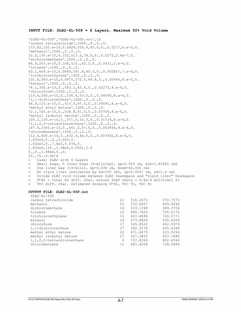
AL/12-10/WP/WTS:SLB2 DAC Report-Rev 2 Dec 2010.docx 136082.02000000 12/28/10 4:41 PM A-7
INPUT FILE: SLB2-6L-50P = 6 Layers, Maximum 50% Void Volume
'SLB2-6L-50P','SLB2-6L-50P.out',12
'carbon tetrachloride',1000.,0.,0.,0.
153.82,193.e-10,0.0828,556.4,45.0,0.,0.0217,6.e-5,0.
'methanol',1000.,0.,0.,0.
32.0,135.e-10,0.152,513.2,78.5,0.,0.0272,2.4e-7,0.
'dichloromethane',1000.,0.,0.,0.
84.9,263.e-10,0.104,510.,62.2,0.,0.0431,2.e-6,0.
'toluene',1000.,0.,0.,0.
92.1,669.e-10,0.0849,591.8,40.5,0.,0.002857,7.e-6,0.
'trichloroethylene',1000.,0.,0.,0.
131.4,583.e-10,0.0875,572.0,49.8,0.,0.00640,6.e-5,0.
'butanol',1000.,0.,0.,0.
74.1,300.e-10,0.,563.1,43.6,0.,0.02273,8.e-6,0.
'chloroform',1000.,0.,0.,0.
119.4,260.e-10,0.,536.4,53.0,0.,0.04545,8.e-6,0.
'1,1-dichloroethene',1000.,0.,0.,0.
96.9,110.e-10,0.,513.0,47.5,0.,0.09091,8.e-6,0.
'methyl ethyl ketone',1000.,0.,0.,0.
72.1,165.e-10,0.,536.8,41.5,0.,0.03704,8.e-6,0.
'methyl isobutyl ketone',1000.,0.,0.,0.
100.2,130.e-10,0.,571.0,32.3,0.,0.01724,8.e-6,0.
'1,1,2,2-tetrachloroethane',1000.,0.,0.,0.
167.9,2300.e-10,0.,661.2,57.6,0.,0.003846,8.e-6,0.
'chlorobenzene',1000.,0.,0.,0.
112.6,600.e-10,0.,632.4,44.6,0.,0.007692,8.e-6,0.
1.832e5,0.,0.,0.063,0.
1.832e5,0.,7.4e5,0.036,0.
1.832e5,150.,1.48e6,0.0001,1.4
0.,0.,1.48e6,0.,0.
25.,76.,6.6e-4
c Case: SLB2 with 6 Layers
c Small bags, 5 inner bags (5-mils/ea), xp=0.063 cm, Aib=1.832E5 cm2
c One liner bag (14-mils), xp=0.036 cm, Aswb=42,000 cm2
c No rigid liner (estimated by Ad=150 cm2, xp=0.0001 cm, xd=1.4 cm)
c Divide SLB2 void volume between SLB2 headspace and "rigid liner" headspace
c D*H2 = total H2 diff. char. across SLB2 vents = 6.6e-4 mol/s/mol fr
c VOC diff. char. estimated knowing D*H2, VOC Tc, VOC Pc
OUTPUT FILE: SLB2-6L-50P.out
SLB2-6L-50P
carbon tetrachloride 21 516.2672 570.7573
methanol 21 372.6007 409.4692
dichloromethane 16 533.1248 589.3704
toluene 10 680.7626 745.6172
trichloroethylene 11 667.6696 726.0771
butanol 16 573.8828 630.9269
chloroform 17 545.8522 602.6979
1,1-dichloroethene 27 392.3178 435.6346
methyl ethyl ketone 22 471.6679 523.9156
methyl isobutyl ketone 27 457.3835 507.7685
1,1,2,2-tetrachloroethane 6 737.8269 802.4566
chlorobenzene 11 665.4208 728.0884
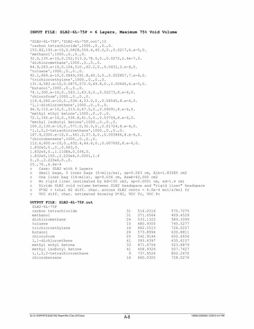
AL/12-10/WP/WTS:SLB2 DAC Report-Rev 2 Dec 2010.docx 136082.02000000 12/28/10 4:41 PM A-8
INPUT FILE: SLB2-6L-75P = 6 Layers, Maximum 75% Void Volume
'SLB2-6L-75P','SLB2-6L-75P.out',12
'carbon tetrachloride',1000.,0.,0.,0.
153.82,193.e-10,0.0828,556.4,45.0,0.,0.0217,6.e-5,0.
'methanol',1000.,0.,0.,0.
32.0,135.e-10,0.152,513.2,78.5,0.,0.0272,2.4e-7,0.
'dichloromethane',1000.,0.,0.,0.
84.9,263.e-10,0.104,510.,62.2,0.,0.0431,2.e-6,0.
'toluene',1000.,0.,0.,0.
92.1,669.e-10,0.0849,591.8,40.5,0.,0.002857,7.e-6,0.
'trichloroethylene',1000.,0.,0.,0.
131.4,583.e-10,0.0875,572.0,49.8,0.,0.00640,6.e-5,0.
'butanol',1000.,0.,0.,0.
74.1,300.e-10,0.,563.1,43.6,0.,0.02273,8.e-6,0.
'chloroform',1000.,0.,0.,0.
119.4,260.e-10,0.,536.4,53.0,0.,0.04545,8.e-6,0.
'1,1-dichloroethene',1000.,0.,0.,0.
96.9,110.e-10,0.,513.0,47.5,0.,0.09091,8.e-6,0.
'methyl ethyl ketone',1000.,0.,0.,0.
72.1,165.e-10,0.,536.8,41.5,0.,0.03704,8.e-6,0.
'methyl isobutyl ketone',1000.,0.,0.,0.
100.2,130.e-10,0.,571.0,32.3,0.,0.01724,8.e-6,0.
'1,1,2,2-tetrachloroethane',1000.,0.,0.,0.
167.9,2300.e-10,0.,661.2,57.6,0.,0.003846,8.e-6,0.
'chlorobenzene',1000.,0.,0.,0.
112.6,600.e-10,0.,632.4,44.6,0.,0.007692,8.e-6,0.
1.832e5,0.,0.,0.063,0.
1.832e5,0.,1.110E6,0.036,0.
1.832e5,150.,2.220e6,0.0001,1.4
0.,0.,2.220e6,0.,0.
25.,76.,6.6e-4
c Case: SLB2 with 6 Layers
c Small bags, 5 inner bags (5-mils/ea), xp=0.063 cm, Aib=1.832E5 cm2
c One liner bag (14-mils), xp=0.036 cm, Aswb=42,000 cm2
c No rigid liner (estimated by Ad=150 cm2, xp=0.0001 cm, xd=1.4 cm)
c Divide SLB2 void volume between SLB2 headspace and "rigid liner" headspace
c D*H2 = total H2 diff. char. across SLB2 vents = 6.6e-4 mol/s/mol fr
c VOC diff. char. estimated knowing D*H2, VOC Tc, VOC Pc
OUTPUT FILE: SLB2-6L-75P.out
SLB2-6L-75P
carbon tetrachloride 31 514.0316 570.7275
methanol 31 371.0564 409.4529
dichloromethane 24 533.1322 589.3399
toluene 15 680.9355 745.5277
trichloroethylene 16 662.5513 726.0227
butanol 24 573.8994 630.8811
chloroform 25 542.9144 602.6656
1,1-dichloroethene 41 393.6397 435.6157
methyl ethyl ketone 33 471.6754 523.8879
methyl isobutyl ketone 41 458.9326 507.7427
1,1,2,2-tetrachloroethane 9 737.9526 802.2472
chlorobenzene 16 660.0305 728.0276

Attachment D
Supplemental Information
Certificate of Compliance No. 9305 for the Model No. TRUPACT‐III Package

NRC FORM 618 (8-2000) 10 CFR 71
U.S. NUCLEAR REGULATORY COMMISSION
CERTIFICATE OF COMPLIANCEFOR RADIOACTIVE MATERIAL PACKAGES
1. a. CERTIFICATE NUMBER b. REVISION NUMBER c. DOCKET NUMBER d. PACKAGE IDENTIFICATION NUMBER PAGE PAGES
9305 0 71-9305 USA/9305/B(U)F-96 1 OF 4
2. PREAMBLE
a. This certificate is issued to certify that the package (packaging and contents) described in Item 5 below meets the applicable safety standards set forth in Title 10, Code of Federal Regulations, Part 71, “Packaging and Transportation of Radioactive Material.”
b. This certificate does not relieve the consignor from compliance with any requirement of the regulations of the U.S. Department of Transportation or other applicable regulatory agencies, including the government of any country through or into which the package will be transported.
3. THIS CERTIFICATE IS ISSUED ON THE BASIS OF A SAFETY ANALYSIS REPORT OF THE PACKAGE DESIGN OR APPLICATION
a. ISSUED TO (Name and Address) b. TITLE AND IDENTIFICATION OF REPORT OR APPLICATION
AREVA Federal Services LLC 1102 Broadway Plaza, Suite 300 Tacoma, WA 98402
AREVA Federal Services LLC application dated June 30, 2007.
4. CONDITIONS
This certificate is conditional upon fulfilling the requirements of 10 CFR Part 71, as applicable, and the conditions specified below.
5.
(a) Packaging
(1) Model No.: TRUPACT-III Package
(2) Description
A package used to transport transuranic waste contained in a Standard Large Box 2 (SLB2) primarily by highway trucks. The packaging body is a rectangular box with an external width of 2,500 mm (98.4 inches), external height of 2,650 mm (104.3 inches), and an external length of 4,288 mm (168.8 inches). The internal cavity dimensions are 1,840 mm (72.4 inches) wide, 2,000 mm (78.7 inches) tall, and 2,790 mm (109.8 inches) long. The TRUPACT-III packaging is comprised of the containment structural assembly (CSA) made from 8-mm inner and outer stainless steel plates with 4-mm thick V-shaped stiffeners in between. A debris shield receptacle is located all around the open end of the CSA inner cavity. The receptacle is a 26-mm x 38-mm cross section bar with a 15-mm wide by 20-mm deep groove cut along its length. The 109 - 120-mm polyurethane foam, 10-mm thick puncture resistant stainless steel plate, 60-mm balsa wood layer, and the 6-mm stainless steel skin form the integral energy-absorbing overpack structure. A 409-mm deep octagonal recess in the bottom end with 6-mm thick stainless steel plate, a 60-mm thick balsa wood layer, a 15-mm thick puncture-resistant stainless steel plate, and a 120-mm thick foam layer protect the bottom end of the packaging during drops or punctures. A rectangular closure lid made from 4-mm thick V-shaped stiffeners sandwiched between an inner and an outer 12-mm thick stainless steel plate is attached to the packaging body
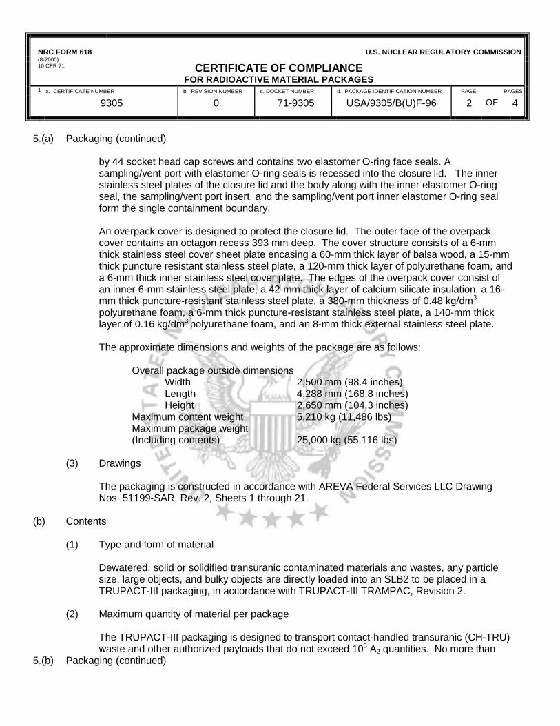
NRC FORM 618 (8-2000) 10 CFR 71
U.S. NUCLEAR REGULATORY COMMISSION
CERTIFICATE OF COMPLIANCEFOR RADIOACTIVE MATERIAL PACKAGES
1 a. CERTIFICATE NUMBER b. REVISION NUMBER c. DOCKET NUMBER d. PACKAGE IDENTIFICATION NUMBER PAGE PAGES
9305 0 71-9305 USA/9305/B(U)F-96 2 OF 4
5.(a) Packaging (continued) by 44 socket head cap screws and contains two elastomer O-ring face seals. A sampling/vent port with elastomer O-ring seals is recessed into the closure lid. The inner stainless steel plates of the closure lid and the body along with the inner elastomer O-ring seal, the sampling/vent port insert, and the sampling/vent port inner elastomer O-ring seal form the single containment boundary.
An overpack cover is designed to protect the closure lid. The outer face of the overpack cover contains an octagon recess 393 mm deep. The cover structure consists of a 6-mm thick stainless steel cover sheet plate encasing a 60-mm thick layer of balsa wood, a 15-mm thick puncture resistant stainless steel plate, a 120-mm thick layer of polyurethane foam, and a 6-mm thick inner stainless steel cover plate. The edges of the overpack cover consist of an inner 6-mm stainless steel plate, a 42-mm thick layer of calcium silicate insulation, a 16-mm thick puncture-resistant stainless steel plate, a 380-mm thickness of 0.48 kg/dm3 polyurethane foam, a 6-mm thick puncture-resistant stainless steel plate, a 140-mm thick layer of 0.16 kg/dm3 polyurethane foam, and an 8-mm thick external stainless steel plate.
The approximate dimensions and weights of the package are as follows:
Overall package outside dimensions
Width 2,500 mm (98.4 inches) Length 4,288 mm (168.8 inches)
Height 2,650 mm (104.3 inches) Maximum content weight 5,210 kg (11,486 lbs)
Maximum package weight (Including contents) 25,000 kg (55,116 lbs)
(3) Drawings
The packaging is constructed in accordance with AREVA Federal Services LLC Drawing Nos. 51199-SAR, Rev. 2, Sheets 1 through 21.
(b) Contents
(1) Type and form of material
Dewatered, solid or solidified transuranic contaminated materials and wastes, any particle size, large objects, and bulky objects are directly loaded into an SLB2 to be placed in a TRUPACT-III packaging, in accordance with TRUPACT-III TRAMPAC, Revision 2.
(2) Maximum quantity of material per package
The TRUPACT-III packaging is designed to transport contact-handled transuranic (CH-TRU) waste and other authorized payloads that do not exceed 105 A2 quantities. No more than
5.(b) Packaging (continued)

NRC FORM 618 (8-2000) 10 CFR 71
U.S. NUCLEAR REGULATORY COMMISSION
CERTIFICATE OF COMPLIANCEFOR RADIOACTIVE MATERIAL PACKAGES
1. a. CERTIFICATE NUMBER b. REVISION NUMBER c. DOCKET NUMBER d. PACKAGE IDENTIFICATION NUMBER PAGE PAGES
9305 0 71-9305 USA/9305/B(U)F-96 3 OF 4
325 grams of Pu-239 fissile gram equivalent (FGE) is generally allowed per TRUPACT-III package. Per the TRUPACT-III TRAMPAC, Revision 2, the FGE limit per TRUPACT-III package may be increased if the payload is documented to contain Pu-240. A TRUPACT-III payload shall not contain greater than 1 percent by weight beryllium and/or beryllium oxide nor machine compacted waste. Only one SLB2 may be loaded in a TRUPACT-III package at a time.
(3) Maximum decay heat per package not to exceed 80 watts. 5.(c) Criticality Safety Index (CSI): 0 6. The package is for transport of the CH–TRU materials and other authorized payloads that are limited
in form to solid or solidified material. Materials must be restricted to prohibit explosives, corrosives, nonradioactive pyrophorics, and pressurized containers. Within a payload container, radioactive pyrophorics must not exceed 1 percent by weight, and residual liquid volumes greater than 1 percent are prohibited.
7. Limits for physical, nuclear, chemical, and gas generation properties shall be as defined in the
TRUPACT-III TRAMPAC, Revision 2. 8. Hydrogen must be limited to a molar quantity that would be no more than 5% by the volume of the
innermost layer of confinement during transport. 9. Each payload shipping container must be assigned to a shipping category in accordance with
TRUPACT-III TRAMPAC, Revision 2, Section 5.0.
10. The gas generated in the payload and released into the cavity shall be controlled to maintain the
pressure within the containment vessel below the acceptable Maximum Normal Operating Pressure of 25 psig.
11. Venting and aspiration are required to the TRUPACT-III containers stored in an unvented condition
prior to transport, to ensure equilibration of gases that may have accumulated in the closed container in accordance with TRUPACT-III TRAMPAC, Revision 2, Section 5.3.
12. In addition to the requirements of Subpart G of 10 CFR Part 71:

NRC FORM 618 (8-2000) 10 CFR 71
U.S. NUCLEAR REGULATORY COMMISSION
CERTIFICATE OF COMPLIANCEFOR RADIOACTIVE MATERIAL PACKAGES
1 a. CERTIFICATE NUMBER b. REVISION NUMBER c. DOCKET NUMBER d. PACKAGE IDENTIFICATION NUMBER PAGE PAGES
9305 0 71-9305 USA/9305/B(U)F-96 4 OF 4
(a) Each package shall be operated and prepared for shipment in accordance with Chapter 7 of the application, as supplemented.
(b) Each package shall be acceptance tested and maintained in accordance with Chapter 8 of
the application, as supplemented. 13. The package authorized by this certificate is hereby approved for use under the general license
provisions of 10 CFR 71.17. 14. Transport by air of fissile material is not authorized. 15. Expiration date: June 30, 2015.
REFERENCES AREVA Federal Services LLC application dated June 30, 2007, as amended January 26, 2010 and May 28, 2010.
FOR THE U.S. NUCLEAR REGULATORY COMMISSION /RA/
Pierre Saverot, Acting Chief Licensing Branch Division of Spent Fuel Storage and Transportation Office of Nuclear Material Safety and Safeguards
Date: June 1, 2010

TRUPACT‐III TRAMPAC Rev. 2, May 2010, Section 2.4 Filter Vents

TRUPACT-III TRAMPAC Rev. 2, May 2010
2.4-1
2.4 Filter Vents
2.4.1 Requirements Each payload container to be transported in the TRUPACT-III shall have one or more filter vents meeting the minimum specifications of Table 2.4-1 and this section. Specifications for filter vents in plastic bags and other inner layers used as confinement layers within the payload container are also included in Table 2.4-1.
Filter vents for the payload container shall be legibly marked or be traceable to ensure both (1) identification of the supplier and (2) date of manufacture, lot number, or unique serial number.
The filter vent housing and element for the payload container shall have an operating temperature range from –40C to +70C (-40F to +158F). The filter vent threads shall be compatible with the bung in the container.
2.4.2 Methods of Compliance and Verification Compliance shall be by one, or a combination, of the following methods:
Administrative and procurement controls demonstrating that filter vents have been procured to the specifications of Section 2.4.1, Requirements
Visual inspection to the specifications of Section 2.4.1, Requirements
Sampling by measurement of filter characteristics to the specifications of Section 2.4.1, Requirements.
If sampling by measurement is selected as the compliance method, the test methods used to determine the compliance of filter vents with the minimum performance-based requirements specified in Table 2.4-1 and this section shall be directed by procedures under a QA program.
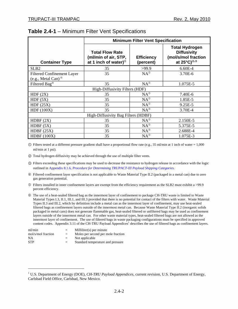
TRUPACT-III TRAMPAC Rev. 2, May 2010
2.4-2
Table 2.4-1 – Minimum Filter Vent Specifications
Container Type
Minimum Filter Vent Specification
Total Flow Rate (ml/min of air, STP, at 1 inch of water)
Efficiency (percent)
Total Hydrogen Diffusivity
(mol/s/mol fraction at 25°C),
SLB2 35 >99.9 6.60E-4 Filtered Confinement Layer (e.g., Metal Can)
35 NA 3.70E-6
Filtered Bag 35 NA 1.075E-5 High-Diffusivity Filters (HDF)
HDF (2X) 35 NA 7.40E-6 HDF (5X) 35 NA 1.85E-5 HDF (25X) 35 NA 9.25E-5 HDF (100X) 35 NA 3.70E-4
High-Diffusivity Bag Filters (HDBF) HDBF (2X) 35 NA 2.150E-5 HDBF (5X) 35 NA 5.375E-5 HDBF (25X) 35 NA 2.688E-4 HDBF (100X) 35 NA 1.075E-3
① Filters tested at a different pressure gradient shall have a proportional flow rate (e.g., 35 ml/min at 1 inch of water = 1,000 ml/min at 1 psi).
② Total hydrogen diffusivity may be achieved through the use of multiple filter vents.
③ Filters exceeding these specifications may be used to decrease the resistance to hydrogen release in accordance with the logic outlined in Appendix 8.1.6, Procedure for Determining TRUPACT-III Payload Shipping Categories.
Filtered confinement layer specification is not applicable to Waste Material Type II.2 (packaged in a metal can) due to zero gas generation potential.
Filters installed in inner confinement layers are exempt from the efficiency requirement as the SLB2 must exhibit a >99.9 percent efficiency.
The use of a heat-sealed filtered bag as the innermost layer of confinement to package CH-TRU waste is limited to Waste Material Types I.3, II.1, III.1, and III.3 provided that there is no potential for contact of the filters with water. Waste Material Types II.3 and III.2, which by definition include a metal can as the innermost layer of confinement, may use heat-sealed filtered bags as confinement layers outside of the innermost metal can. Because Waste Material Type II.2 (inorganic solids packaged in metal cans) does not generate flammable gas, heat-sealed filtered or unfiltered bags may be used as confinement layers outside of the innermost metal can. For other waste material types, heat-sealed filtered bags are not allowed as the innermost layer of confinement. The use of filtered bags in waste packaging configurations must be specified in approved content codes. Appendix 3.11 of the CH-TRU Payload Appendices1 describes the use of filtered bags as confinement layers.
ml/min = Milliliter(s) per minute mol/s/mol fraction = Moles per second per mole fraction NA = Not applicable STP = Standard temperature and pressure
1 U.S. Department of Energy (DOE), CH-TRU Payload Appendices, current revision, U.S. Department of Energy, Carlsbad Field Office, Carlsbad, New Mexico.
TRUPACT‐III TRAMPAC, Rev. 2, May 2010, Section 2.8 Specification for Authorized Payloads
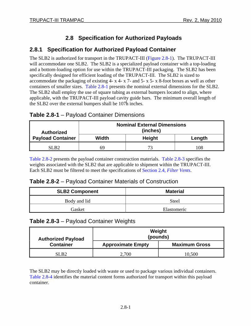
TRUPACT-III TRAMPAC Rev. 2, May 2010
2.8-1
2.8 Specification for Authorized Payloads
2.8.1 Specification for Authorized Payload Container The SLB2 is authorized for transport in the TRUPACT-III (Figure 2.8-1). The TRUPACT-III will accommodate one SLB2. The SLB2 is a specialized payload container with a top-loading and a bottom-loading option for use within the TRUPACT-III packaging. The SLB2 has been specifically designed for efficient loading of the TRUPACT-III. The SLB2 is sized to accommodate the packaging of existing 4- x 4- x 7- and 5- x 5- x 8-foot boxes as well as other containers of smaller sizes. Table 2.8-1 presents the nominal external dimensions for the SLB2. The SLB2 shall employ the use of square tubing as external bumpers located to align, where applicable, with the TRUPACT-III payload cavity guide bars. The minimum overall length of the SLB2 over the external bumpers shall be 107¡ inches.
Table 2.8-1 – Payload Container Dimensions
Authorized Payload Container
Nominal External Dimensions (inches)
Width Height Length
SLB2 69 73 108
Table 2.8-2 presents the payload container construction materials. Table 2.8-3 specifies the weights associated with the SLB2 that are applicable to shipment within the TRUPACT-III. Each SLB2 must be filtered to meet the specifications of Section 2.4, Filter Vents.
Table 2.8-2 – Payload Container Materials of Construction SLB2 Component Material
Body and lid Steel
Gasket Elastomeric
Table 2.8-3 – Payload Container Weights
Authorized Payload Container
Weight (pounds)
Approximate Empty Maximum Gross
SLB2 2,700 10,500
The SLB2 may be directly loaded with waste or used to package various individual containers. Table 2.8-4 identifies the material content forms authorized for transport within this payload container.

TRUPACT-III TRAMPAC Rev. 2, May 2010
2.8-2
Top-Loading Configuration
Bottom-Loading Configuration
Figure 2.8-1 – Schematic of SLB2
(Dimensions shown are nominal)
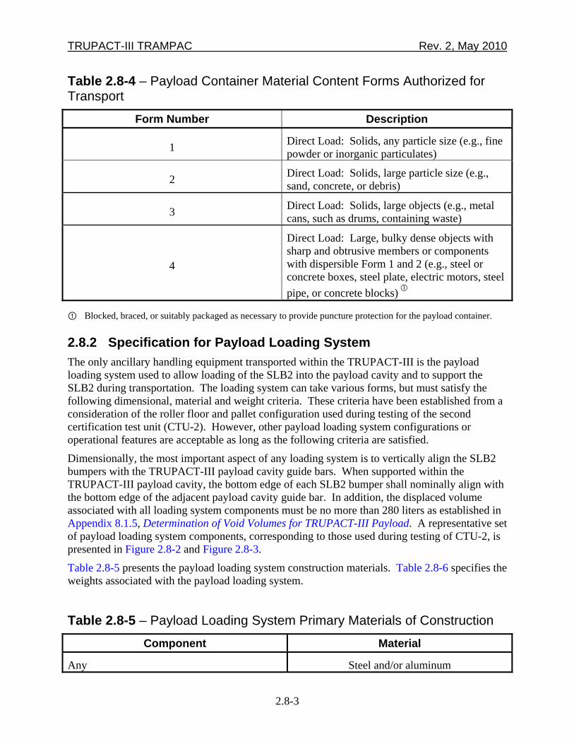
TRUPACT-III TRAMPAC Rev. 2, May 2010
2.8-3
Table 2.8-4 – Payload Container Material Content Forms Authorized for Transport
Form Number Description
1 Direct Load: Solids, any particle size (e.g., fine powder or inorganic particulates)
2 Direct Load: Solids, large particle size (e.g., sand, concrete, or debris)
3 Direct Load: Solids, large objects (e.g., metal cans, such as drums, containing waste)
4
Direct Load: Large, bulky dense objects with sharp and obtrusive members or components with dispersible Form 1 and 2 (e.g., steel or concrete boxes, steel plate, electric motors, steel pipe, or concrete blocks)
① Blocked, braced, or suitably packaged as necessary to provide puncture protection for the payload container.
2.8.2 Specification for Payload Loading System The only ancillary handling equipment transported within the TRUPACT-III is the payload loading system used to allow loading of the SLB2 into the payload cavity and to support the SLB2 during transportation. The loading system can take various forms, but must satisfy the following dimensional, material and weight criteria. These criteria have been established from a consideration of the roller floor and pallet configuration used during testing of the second certification test unit (CTU-2). However, other payload loading system configurations or operational features are acceptable as long as the following criteria are satisfied.
Dimensionally, the most important aspect of any loading system is to vertically align the SLB2 bumpers with the TRUPACT-III payload cavity guide bars. When supported within the TRUPACT-III payload cavity, the bottom edge of each SLB2 bumper shall nominally align with the bottom edge of the adjacent payload cavity guide bar. In addition, the displaced volume associated with all loading system components must be no more than 280 liters as established in Appendix 8.1.5, Determination of Void Volumes for TRUPACT-III Payload. A representative set of payload loading system components, corresponding to those used during testing of CTU-2, is presented in Figure 2.8-2 and Figure 2.8-3.
Table 2.8-5 presents the payload loading system construction materials. Table 2.8-6 specifies the weights associated with the payload loading system.
Table 2.8-5 – Payload Loading System Primary Materials of Construction Component Material
Any Steel and/or aluminum
TRUPACT-III TRAMPAC Rev. 2, May 2010
2.8-4
Table 2.8-6 – Payload Loading System Weights
Component Nominal Gross Weight
(pounds)
Full set of payload loading system components supporting an SLB2
986

TRUPACT‐III TRAMPAC, Rev. 2, May 2010, Appendix 8.1.5 Determination of Void Volumes for TRUPACT‐III Payload

TRUPACT-III TRAMPAC Rev. 2, May 2010
8.1.5-1
8.1.5 Determination of Void Volumes for TRUPACT-III Payload This appendix documents the determination of the following TRUPACT-III package void volumes:
Empty TRUPACT-III containment vessel
Empty SLB2
TRUPACT-III containment vessel when loaded with one SLB2.
8.1.5.1 Void Volume Calculation for Empty TRUPACT-III Containment Vessel The internal dimensions of the TRUPACT-III containment vessel are as follows:
Height = 2,000 mm (200 cm)
Length = 2,790 mm (279 cm)
Width = 1,840 mm (184 cm).
The internal volume (in liters) of the TRUPACT-III containment vessel excluding the volumes occupied by the interior protruding features and the ancillary handling equipment is:
liters10,2671,000cm
liter1184cm279cm200cmW*L*H 3
The interior protruding features of the TRUPACT-III containment vessel consist of the rails/guide channels, the lid shear lip, the debris shield, eight full cavity length 1-inch by 3-inch guide rails, and three full cavity width 1-inch by 3-inch guide rails with bumpers bolted on to control cavity length. The external volume associated with these interior protruding features is as follows:
liters 83Volother
Therefore, the internal volume of the TRUPACT-III containment vessel accounting for the total volume occupied by the interior protruding features is:
liters 18410,liters 83liters10,267
The total volume occupied by the ancillary handling equipment (i.e., payload loading system) is limited to the following:
liters 280Volloadsys (corresponds to as-tested roller floor and pallet used in CTU-2)
Thus, the internal volume of the TRUPACT-III containment vessel taking into account the ancillary handling equipment is:
liters 9,904Volliters 10,184IVol loadsysTIII
8.1.5.2 Void Volume Calculation for Empty SLB2 The internal dimensions of the SLB2 are as follows:
Height = 66.5 in. (168.910 cm)
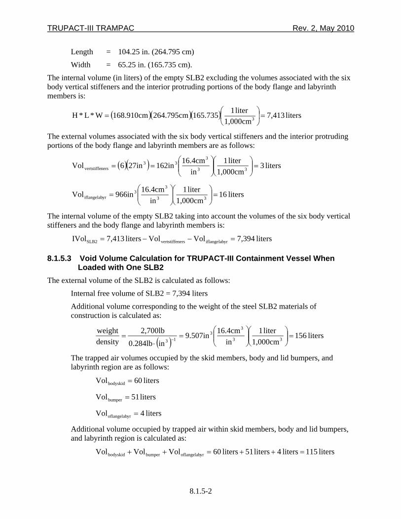
TRUPACT-III TRAMPAC Rev. 2, May 2010
8.1.5-2
Length = 104.25 in. (264.795 cm)
Width = 65.25 in. (165.735 cm).
The internal volume (in liters) of the empty SLB2 excluding the volumes associated with the six body vertical stiffeners and the interior protruding portions of the body flange and labyrinth members is:
liters 7,4131,000cm
liter 1165.735264.795cmcm168.910W*L*H 3
The external volumes associated with the six body vertical stiffeners and the interior protruding portions of the body flange and labyrinth members are as follows:
liters 31,000cm
liter 1in
16.4cm162in27in6Vol 33
333
nersvertstiffe
liters 161,000cm
liter 1in
16.4cm966inVol 33
33
yriflangelab
The internal volume of the empty SLB2 taking into account the volumes of the six body vertical stiffeners and the body flange and labyrinth members is:
liters 7,394VolVolliters 7,413IVol yriflangelabnersvertstiffeSLB2
8.1.5.3 Void Volume Calculation for TRUPACT-III Containment Vessel When Loaded with One SLB2
The external volume of the SLB2 is calculated as follows:
Internal free volume of SLB2 = 7,394 liters
Additional volume corresponding to the weight of the steel SLB2 materials of construction is calculated as:
liters 156
1,000cmliter 1
in16.4cm9.507in
in0.284lb2,700lb
densityweight
33
33
13
The trapped air volumes occupied by the skid members, body and lid bumpers, and labyrinth region are as follows:
liters 60Volbodyskid
liters 51Volbumper
liters 4Vol yroflangelab
Additional volume occupied by trapped air within skid members, body and lid bumpers, and labyrinth region is calculated as:
liters 115liters 4liters 51liters 60VolVolVol yroflangelabbumperbodyskid

TRUPACT-III TRAMPAC Rev. 2, May 2010
8.1.5-3
Therefore, the external volume of the SLB2 is:
liters 7,665liters 115liters 156liters 7,394
Thus, the internal volume of the TRUPACT-III containment vessel when loaded with one SLB2 is:
liters 2,239liters 7,665liters 9,904IVolTIIIw/SLB2
8.1.5.4 Summary of Calculations The TRUPACT-III package void volumes are as follows:
Empty TRUPACT-III containment vessel = 9,904 liters
Empty SLB2 = 7,394 liters
TRUPACT-III containment vessel when loaded with one SLB2 = 2,239 liters.

TRUPACT-III TRAMPAC Rev. 2, May 2010
8.1.5-4
This page intentionally left blank.
TRUPACT‐III TRAMPAC, Rev. 2, May 2010, Appendix 8.1.6 Procedure for Determining TRUPACT‐III Payload Shipping
Categories
TRUPACT-III TRAMPAC Rev. 2, May 2010
8.1.6-1
8.1.6 Procedure for Determining TRUPACT-III Payload Shipping Categories
For any given SLB2, the shipping category provides a basis to determine the gas generation potential of the contents and the resistance to gas release of the packaging configuration. This enables evaluation of compliance with the gas generation requirements. A description of the shipping category notation is presented in the following sections.
8.1.6.1 Shipping Category Notation The shipping category notation is a ten-digit numeric code:
XX YYYY ZZZZ where,
XX = The waste type, which indicates the chemical composition of the waste
YYYY = The G value, or gas generation potential, of the waste material type multiplied by 102
ZZZZ = The resistance to hydrogen release of the packaging configuration multiplied by 10-4.
A description of each of the parameters follows. Waste Type Payloads are subdivided into three waste types based on physical and chemical form as shown in Table 8.1.6-1. Table 8.1.6-1 also shows the shipping category notation denoting each waste type. Waste Material Type The three waste types may be further subdivided into waste material types. The waste material types define the gas generation potential of the waste, and a listing of the chemicals/materials allowed in each waste material type is presented in Tables 4.3-1 through 4.3-7. An effective bounding G value quantifying the gas generation potential of each waste material type is assigned based on the chemicals allowed. Dose-dependent G values are applicable to containers of CH-TRU waste materials of Waste Material Type II.1 and Waste Type III that meet a watt*year criteria of greater than 0.012. The determination of bounding G values for each waste material type is described in Appendices 3.2 and 3.3 of the CH-TRU Payload Appendices1.
1 U.S. Department of Energy (DOE), CH-TRU Payload Appendices, U.S. Department of Energy, Carlsbad Field Office, Carlsbad, New Mexico.

TRUPACT-III TRAMPAC Rev. 2, May 2010
8.1.6-2
Table 8.1.6-2 presents the waste material types and their respective bounding G values, along with the shipping category notation denoting the bounding G value. Table 8.1.6-1 — Summary of Payload Waste Types
Waste Type Waste Type
(XX) Description and Examples I 10 Solidified Aqueous or Homogeneous Inorganic Solids
(<1 percent organics - not including packaging) - absorbed, adsorbed or solidified inorganic liquid - soils, solidified particulates, or sludges formed from
precipitates - concreted inorganic particulate waste
II 20 Solid Inorganics - glass, metal, crucibles - other solid inorganics
III 30 Solid Organics - plastics (e.g., polyethylene, polyvinyl chloride) - cellulose (e.g., paper, cloth, wood) - cemented organic solids - other solid organics
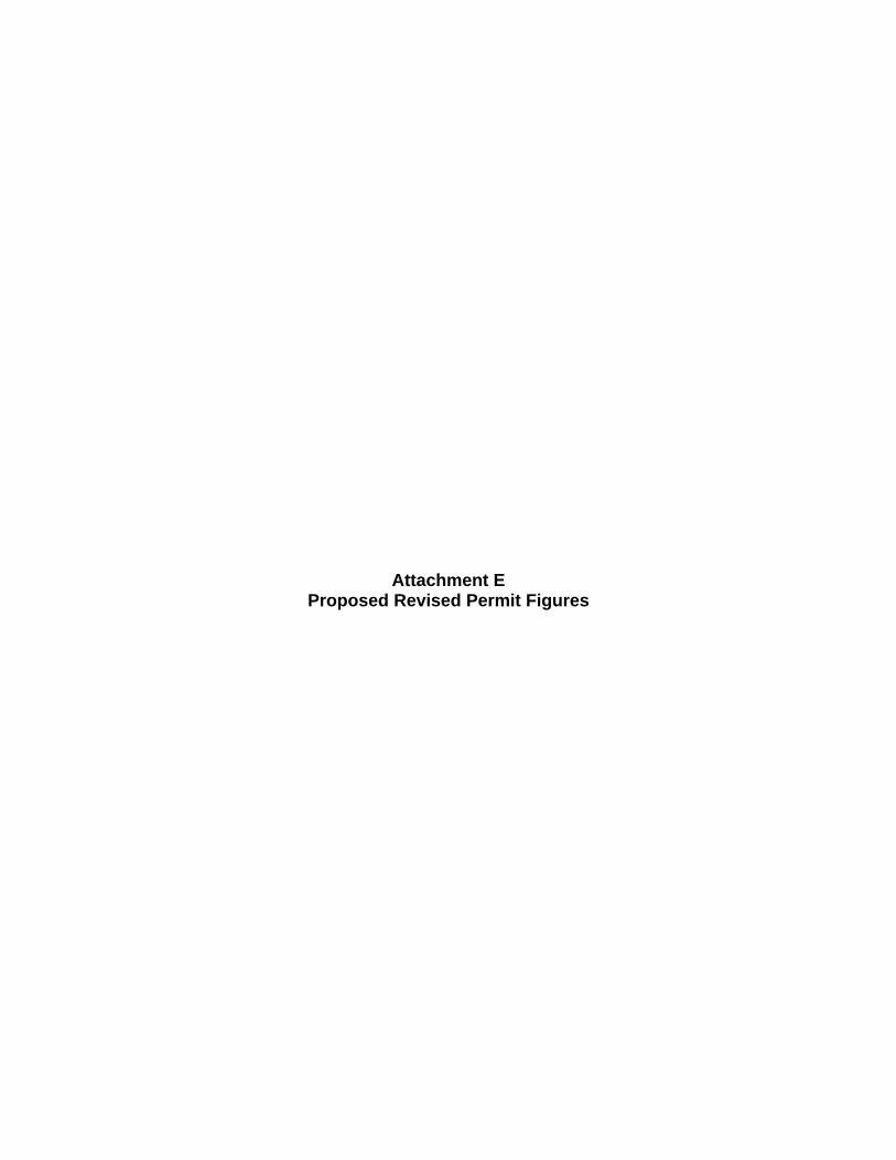
Attachment E
Proposed Revised Permit Figures

Figure A1-1 Waste Handling Building - CH TRU Mixed Waste Container Storage and Surge Areas
""""" ", ROO~
0 103
ROOM 112
DERIVED ASTE AREA
~
ROOM AIRLOCK 107 108
Drawing Not To Scale
0 0 0 0
UiJjJ
(D~DJ 0 0 0 0
CHBAY BLDG. 411
TMF 412
r4+-- CH Bay Surge Area
LEGEND I I CH BAY STORAG E '--------' AR EA
~ DERIVED WASTE STORAGE 1>..~'-'>.O"'-"o.J AR EA
I SU RGE STORAG E AREA '--------'
AIRLOQ( ", ROO~
0 103
ROOM 112
DERIVED ASTE AREA
~
ROOM AIRLOCK 107 108
Drawing Not To Scale
0 0 0 0
(tijjJ
(D~DJ 0 0 0 0
CHBAY BLDG. 411
TMF 412
r4+-- CH Bay Surge Area
LEGEND I I CH BAY STORAG E '--------' AR EA
~ DERIVED WASTE STORAGE 1>..~"-"'''''''o.J AR EA
I SURGE STORAGE AR EA '------'
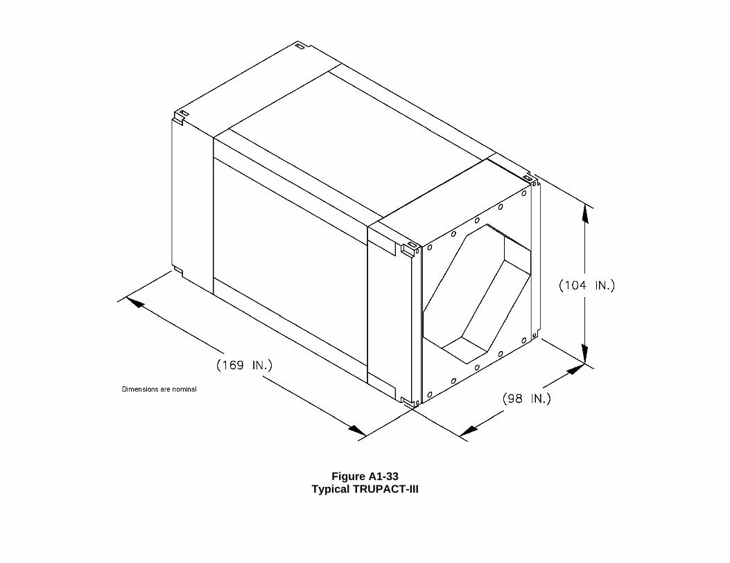
Figure A1-33 Typical TRUPACT-III
o o
(104 IN.)
(169 IN.) o o
Dimensions are nominal o (98 IN.)
o o
(104 IN.)
(169 IN.) o o
Dimensions are nominal o (98 IN.)
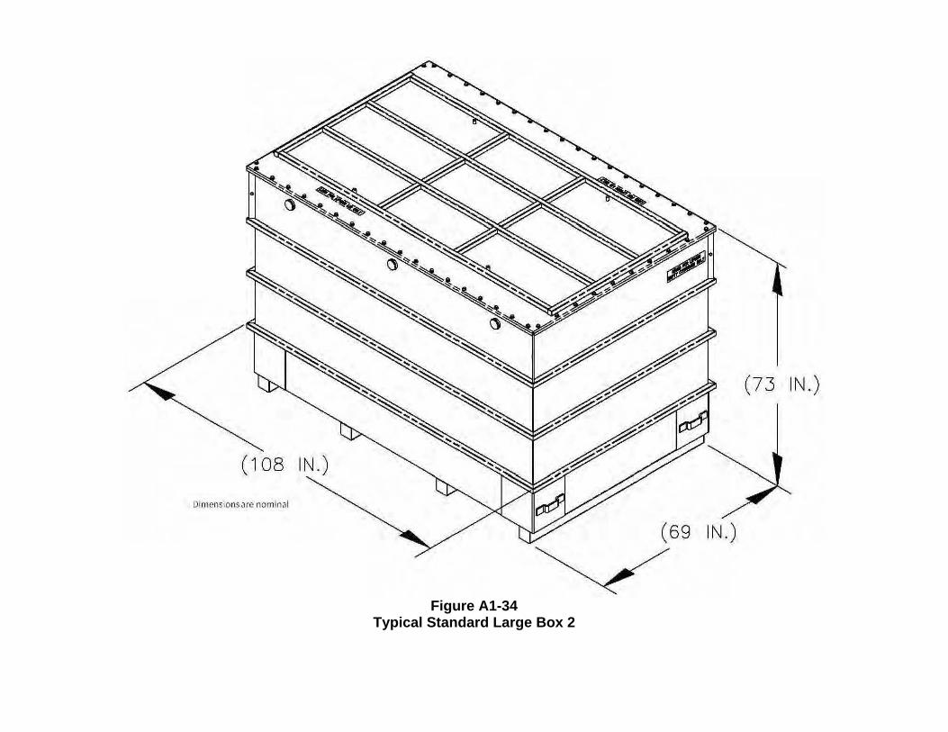
Figure A1-34
Typical Standard Large Box 2
(73 IN.)
D!mensions<l(c nom I",]!
(69 IN.)
(73 IN.)
DimC'nsionsarc nomIna!
(69 IN.)
Figure A1-35
Typical Yard Transfer Vehicle
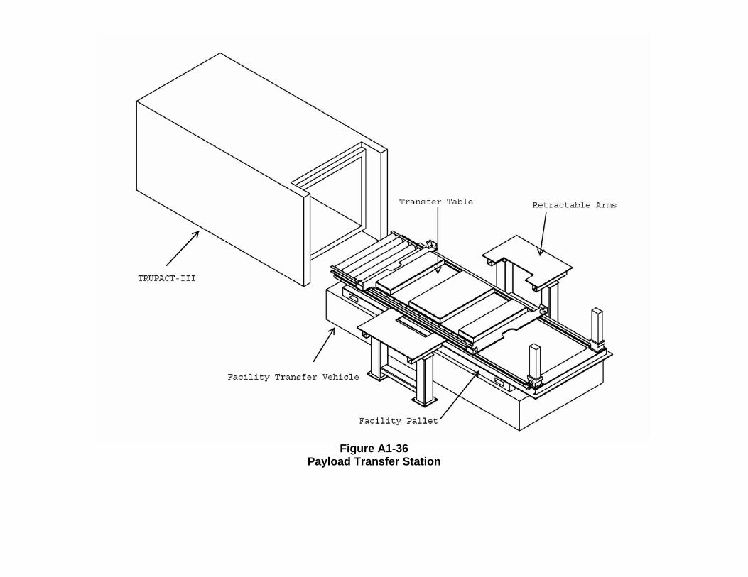
Figure A1-36
Payload Transfer Station

Figure A4-3a
Typical Transport Route for TRUPACT-III and Standard Large Box 2
" ' ,
[ I . 00 00 •
00 0 0
c Z' []
"'
CflAR!ilNG ; l ATl~S ,
[ I . \ . 00 00
•
00 00
c Z' []
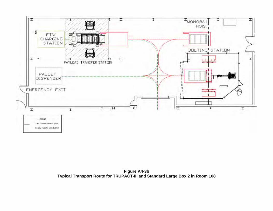
Figure A4-3b Typical Transport Route for TRUPACT-III and Standard Large Box 2 in Room 108
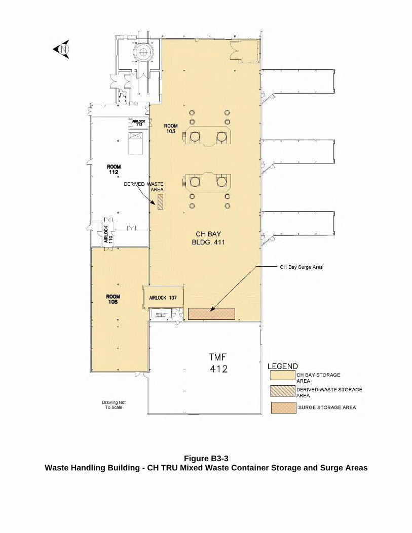
Figure B3-3 Waste Handling Building - CH TRU Mixed Waste Container Storage and Surge Areas
""""" ", ROO~
0 103
ROOM 112
DERIVED ASTE AREA
~
ROOM AIRLOCK 107 108
Drawing Not To Scale
0 0 0 0
UiJjJ
(D~DJ 0 0 0 0
CHBAY BLDG. 411
TMF 412
r4+-- CH Bay Surge Area
LEGEND I I CH BAY STORAG E '--------' AR EA
~ DERIVED WASTE STORAGE 1>..~'-'>.O"'-"o.J AR EA
I SU RGE STORAG E AREA '--------'
AIRLOQ( ", ROO~
0 103
ROOM 112
DERIVED ASTE AREA
~
ROOM AIRLOCK 107 108
Drawing Not To Scale
0 0 0 0
(tijjJ
(D~DJ 0 0 0 0
CHBAY BLDG. 411
TMF 412
r4+-- CH Bay Surge Area
LEGEND I I CH BAY STORAG E '--------' AR EA
~ DERIVED WASTE STORAGE 1>..~"-"'''''''o.J AR EA
I SURGE STORAGE AR EA '------'