review of the trupact-iii type b shipping package
TRANSCRIPT

REVIEW OF THE TRUPACT-III TYPE B SHIPPING PACKAGE
May 2007
ISO-2 Project Carlsbad, NM
ISO-2 Project WIPP Independent Oversight – DE-AC30-06EW03005
PECOS MANAGEMENT SERVICES, INC.
PECOS MANAGEMENT SERVICES, INC.
ISO-2 Project WIPP Independent Oversight – DE-AC30-06EW03005
Building Quality, Safety, and Integrity into Each Deliverable PECOS Document 07-001 – Page i
REVIEW OF THE TRUPACT-III TYPE B SHIPPING PACKAGE May 2007
TABLE OF CONTENTS
I. PURPOSE AND SCOPE .......................................................................................... 1 II. BACKGROUND......................................................................................................... 1
III. DESIGN AND TESTING REQUIREMENTS ........................................................ 2 IV. DESIGN....................................................................................................................... 5 V. TESTING .................................................................................................................... 8
VI. FINDINGS .................................................................................................................. 9 VII. CONCLUSIONS....................................................................................................... 16
VIII. RECOMMENDATIONS ......................................................................................... 16 REPORT PREPARED BY ................................................................................................... 16 REVIEWERS......................................................................................................................... 16 REFERENCES ...................................................................................................................... 16 BIBLIOGRAPHY ................................................................................................................. 17
This report was prepared as an account of work sponsored by an agency of the United States Government. Neither the United States Government nor any agency thereof, nor PECOS Management Services, Inc, nor any of their employees, make any warranty, express or implied, or assume any liability or responsibility for the accuracy, completeness, or usefulness of any information, apparatus, product, or process disclosed in this report, or represent that its use would not infringe privately owned rights. Reference to any specific commercial product, process, or service by trade name, trademark, manufacturer, or otherwise does not necessarily constitute or imply its endorsement, recommendation, or favoring by the United States Government or any agency thereof. The views and opinions of the authors of this report do not necessarily state or reflect those of the United States Government or any agency thereof.
The contents of this publication may not be copied, reproduced, transmitted, displayed, distributed, altered, or otherwise used in whole or in part in any manner without prior written consent of PECOS Management Services, Inc.
PECOS MANAGEMENT SERVICES, INC.
ISO-2 Project WIPP Independent Oversight – DE-AC30-06EW03005
Building Quality, Safety, and Integrity into Each Deliverable PECOS Document 07-001 – Page ii
Use or disclosure of data contained on this sheet is subject to the restriction printed on the Table of Contents page of this report.
ACRONYMS
ALARA As Low As Reasonably Attainable
ANSI American National Standard Institute, Inc.
ASTM American Society for Testing and Materials CG Center of Gravity CH Contact Handled CTU Certified Test Unit DOE U. S. Department of Energy
HAC Hypothetical Accident Conditions NCT Normal Conditions of Transport NRC Nuclear Regulatory Commission
PECOS PECOS Management Services, Inc.
psig Pound/Square Inch Gauge SLB Standard Large Box SNL Sandia National Laboratory SS Stainless Steel TRU Transuranic TRUPACT-III Transuranic Container Transporter Model 3 UNS Unified Numbering System
VOC Volatile Organic Compound WIPP Waste Isolation Pilot Plant
PECOS MANAGEMENT SERVICES, INC.
ISO-2 Project WIPP Independent Oversight – DE-AC30-06EW03005
Building Quality, Safety, and Integrity into Each Deliverable PECOS Document 07-001 – Page 1
Use or disclosure of data contained on this sheet is subject to the restriction printed on the Table of Contents page of this report.
REVIEW OF THE TRUPACT-III TYPE B SHIPPING PACKAGE
May 2007
I. PURPOSE AND SCOPE The purpose of this report is to provide a review of the testing, safety considerations, and compliance with procedures used for Nuclear Regulatory Commission (NRC) certification of the TRUPACT-III shipping package. The TRUPACT-III is an NRC-defined Type B package designed to retain the integrity of containment and shielding required for its radioactive contents when subjected to normal conditions of transport and hypothetical accident conditions (HAC) set forth in 10 CFR 71. This review addresses the design and testing of TRUPACT-III, which will be used for shipment of contact handled (CH) transuranic (TRU) waste to the Waste Isolation Pilot Plant (WIPP). Original design specifications and revisions to the design in response to changes and concerns from the NRC were evaluated, as were testing procedures and results. PECOS Management Services, Inc. (PECOS) conducted reviews of publicly available literature, regulatory submittals and responses, drawings, and specifications, including those listed in the References and Bibliography sections. TRUPACT-III drop tests were observed by PECOS, and design and testing personnel were interviewed. II. BACKGROUND Nearly 25 percent of the current inventory of CH TRU waste pending disposal at WIPP is packed in boxes that are too large to fit in existing NRC-certified TRUPACT-II or HalfPACT transportation packages. The boxes that currently contain the CH TRU waste are nominally between 1.22- × 1.22- × 2.13-m and 1.52- × 1.52- × 2.44-m in size (4 x 4 x 7 ft to 5 x 5 x 8 ft). Unless a new shipping container is designed and certified by the NRC, waste contained in these oversized boxes will have to be repackaged into smaller containers before they can be transported. Repacking will increase worker exposure and the risk for unplanned releases. The rectangular parallelepiped geometry of the oversized boxes also dictates use of a rectangular cross-section for the payload cavity of a new shipping container rather than the cylindrical cavity of the TRUPACT-II. The three basic design objectives of the TRUPACT-III are: 1) it must match the geometry of the oversized containers; 2) it must meet the requirements of 10 CFR 71 and the As Low As Reasonably Attainable (ALARA) objectives for exposure of workers, the public, and the environment; and 3) it has to be transportable by highway without obtaining oversized permits. The TRUPACT-III is designed and fabricated by Packaging Technology, Inc.

PECOS MANAGEMENT SERVICES, INC.
ISO-2 Project WIPP Independent Oversight – DE-AC30-06EW03005
Building Quality, Safety, and Integrity into Each Deliverable PECOS Document 07-001 – Page 2
Use or disclosure of data contained on this sheet is subject to the restriction printed on the Table of Contents page of this report.
III. DESIGN AND TESTING REQUIREMENTS Design and testing requirements for the TRUPACT-III are specified in 10 CFR 71 and fall into three categories, as exemplified in the following three tables. The general design requirements for all radioactive material packages, as stated in 10 CFR 71.43,1 are presented in Table 1. Test procedures and testing requirements for Type B packages for normal conditions of transport (NCT), as stated in 10 CFR 71.71,2 are presented in Table 2. Test procedures and testing requirements for Type B packages for hypothetical accident conditions (HAC), as stated in 10 CFR 71.73,3 are presented in Table 3.
TABLE 1. General Standards for all Radioactive Material Transport Packages.
STANDARD CRITERIA
Dimension The smallest overall dimension of a package may not be less than 10 cm (4 in).
Tamper Evidence Seal
The outside of a package must incorporate a feature, such as a seal, that is not readily breakable and that, if intact, would be evidence the package has not been opened by unauthorized persons.
Containment System
Each package must include a containment system securely closed by a positive fastening device that cannot be opened unintentionally or by a pressure that may arise within the package.
Materials and Construction
A package must be made of materials and construction that ensure there will be no significant chemical, galvanic, or other reaction among the packaging components, among package contents, or between the packaging components and the package contents⎯including possible reaction resulting from inleakage of water⎯to the maximum credible extent. Account must be taken of the behavior of material under irradiation.
Package Valve
A package valve or other device, the failure of which would allow radioactive contents to escape, must be protected against unauthorized operation and, except for a pressure relief device, must be provided with an enclosure to retain any leakage.
Radioactive Release
A package must be designed, constructed, and prepared for shipment to ensure that under the tests specified in part 71.71, there would be no loss or dispersal of radioactive contents, no significant increase in external surface radiation levels, and no substantial reduction in the effectiveness of the packaging.
Surface Temperature
A package must be designed, constructed, and prepared for shipment so that in still air at 38oC (100oF) and in the shade, no accessible surface of a package would have a temperature exceeding 50oC (122oF) in a nonexclusive use shipment, or 85oC (185oF) in an exclusive use shipment.
Continuous Venting A package may not incorporate a feature intended to allow continuous venting during transport.

PECOS MANAGEMENT SERVICES, INC.
ISO-2 Project WIPP Independent Oversight – DE-AC30-06EW03005
Building Quality, Safety, and Integrity into Each Deliverable PECOS Document 07-001 – Page 3
Use or disclosure of data contained on this sheet is subject to the restriction printed on the Table of Contents page of this report.
Evaluation of each package design under NCT must include a determination of the effect on that design of the conditions and tests specified in Table 2. Separate specimens may be used for the free drop test, the compression test, and the penetration test if each specimen is subjected to the water spray test before being subjected to any of the other tests.
TABLE 2. Evaluation for Normal Conditions Incident to Transport.
EVALUATION CRITERIA DURATION
Ambient Heating 38 degrees C (100 degrees F) 12 hours
Ambient Cooling -40 degrees C (-40 degrees F) 12 hours
Reduced External Pressure 25 kPa (3.5 lbf/in2) absolute N/A
Increased External Pressure 140 kPa (20 lbf/in2) absolute N/A
Vibration Vibration normally incident to transport Not specified
Water Spray Test 5 cm/h (2 in/h) At least 1 hour
Free Drop
Less than 5,000 Kg (Less than 11,000 lbs) - 1.2 m (4 ft.)
5,000 to 10,000 Kg (11,000 to 22,000 lbs) - 0.9 m (3ft.)
10,000 to 15,000 Kg (22,000 to 33,100 lbs) - 0.6 m (2 ft.)
More than 15,000 Kg (More than 33,100 lbs) - 0.3 m (1 ft.)
1.5 to 2.5 hours after the conclusion of the
water spray test
Evaluation for HAC is to be based on sequential application of the tests specified in 10 CFR 71.73, in the order indicated, to determine their cumulative effect on a package or array of packages. An undamaged specimen may be used for the water immersion test. To demonstrate compliance, for both the NCT and HAC requirements, the ambient air temperature before and after the tests (with the exception of the water immersion test) must remain constant at a value between -29o C (-20o F) and +38o C (+100o F). The most unfavorable conditions for the feature under consideration must be used. The initial internal pressure within the containment system must be the maximum normal operating pressure of 25 psig (as stated in Packaging Technology, Inc.’s Draft Certification Test Plan),4 or the most unfavorable pressure, consistent with the testing temperature.

PECOS MANAGEMENT SERVICES, INC.
ISO-2 Project WIPP Independent Oversight – DE-AC30-06EW03005
Building Quality, Safety, and Integrity into Each Deliverable PECOS Document 07-001 – Page 4
Use or disclosure of data contained on this sheet is subject to the restriction printed on the Table of Contents page of this report.
TABLE 3. Evaluation for Hypothetical Accident Conditions.
EVALUATION CRITERIA
Free Drop 9 m (30 ft)
Crush
Drop of a 500-kg (1100-lb) mass from 9 m (30 ft) onto the specimen
The crush test is required only when the specimen has a mass not greater than 500 kg (1100 lb), an overall density not greater than 1000 kg/m3 (62.4 lb/ft3) based on external dimension, and radioactive contents greater than 1000 A2* not as special form radioactive material.
Puncture
A free drop of the specimen through a distance of 1 m (40 in) in a position for which maximum damage is expected, onto the upper end of a solid, vertical, cylindrical, mild steel bar mounted on an essentially unyielding, horizontal surface. The bar must be 15 cm (6 in) in diameter, with the top horizontal and its edge rounded to a radius of not more than 6 mm (0.25 in), and of a length as to cause maximum damage to the package, but not less than 20 cm (8 in) long. The long axis of the bar must be vertical.
Thermal
Exposure of the specimen fully engulfed, except for a simple support system, in a hydrocarbon fuel/air fire of sufficient extent, and in sufficiently quiescent ambient conditions, to provide an average emissivity coefficient of at least 0.9, with an average flame temperature of at least 800 degrees C (1475 degrees F).
Immersion
All packages. A separate, undamaged specimen must be subjected to water pressure equivalent to immersion under a head of water of at least 15 m (50 ft). For test purposes, an external pressure of water of 150 kPa (21.7 lbf/in2) gauge is considered to meet these conditions.
For fissile material subject to Section. 71.55, in those cases where water in-leakage has not been assumed for criticality analysis, immersion under a head of water of at least 0.9 m (3 ft) in the attitude for which maximum leakage is expected.
* A2 means the maximum activity of radioactive material, other than special form material, LSA, and SCO material, permitted in a NRC defined Type A package. This value is either listed in Appendix A, Table A-1, (10 CFR 71), or may be derived in accordance with the procedures prescribed in Appendix A of this part.
To be approved as a Type B package, all the requirements of 10 CFR 71 must be satisfied, and the validated testing results submitted to the NRC for review and certification.
PECOS MANAGEMENT SERVICES, INC.
ISO-2 Project WIPP Independent Oversight – DE-AC30-06EW03005
Building Quality, Safety, and Integrity into Each Deliverable PECOS Document 07-001 – Page 5
Use or disclosure of data contained on this sheet is subject to the restriction printed on the Table of Contents page of this report.
IV. DESIGN
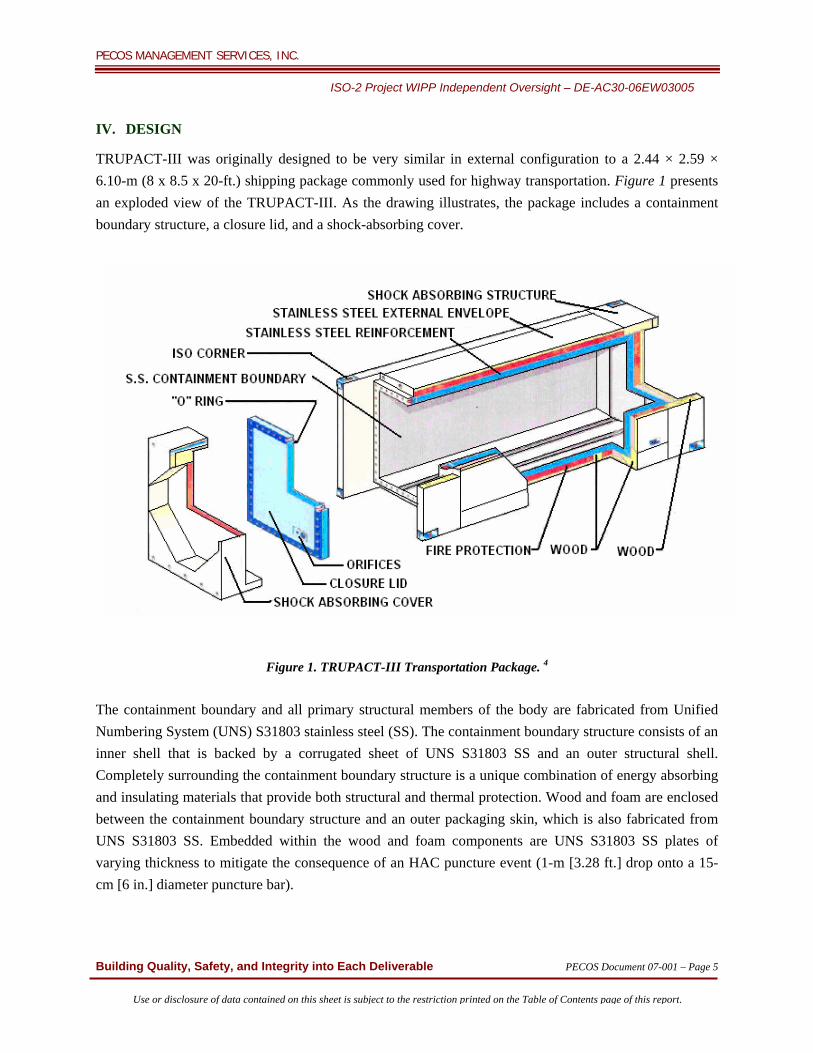
TRUPACT-III was originally designed to be very similar in external configuration to a 2.44 × 2.59 × 6.10-m (8 x 8.5 x 20-ft.) shipping package commonly used for highway transportation. Figure 1 presents an exploded view of the TRUPACT-III. As the drawing illustrates, the package includes a containment boundary structure, a closure lid, and a shock-absorbing cover.
Figure 1. TRUPACT-III Transportation Package. 4
The containment boundary and all primary structural members of the body are fabricated from Unified Numbering System (UNS) S31803 stainless steel (SS). The containment boundary structure consists of an inner shell that is backed by a corrugated sheet of UNS S31803 SS and an outer structural shell. Completely surrounding the containment boundary structure is a unique combination of energy absorbing and insulating materials that provide both structural and thermal protection. Wood and foam are enclosed between the containment boundary structure and an outer packaging skin, which is also fabricated from UNS S31803 SS. Embedded within the wood and foam components are UNS S31803 SS plates of varying thickness to mitigate the consequence of an HAC puncture event (1-m [3.28 ft.] drop onto a 15- cm [6 in.] diameter puncture bar).

PECOS MANAGEMENT SERVICES, INC.
ISO-2 Project WIPP Independent Oversight – DE-AC30-06EW03005
Building Quality, Safety, and Integrity into Each Deliverable PECOS Document 07-001 – Page 6
Use or disclosure of data contained on this sheet is subject to the restriction printed on the Table of Contents page of this report.
In the immediate vicinity of the closure lid O-ring seal, calcium silicate insulation is employed along with a closure bolt protection plate structure to protect the closure area both structurally and thermally. Butyl O-ring seals, in a face seal configuration, form a single level of containment. Lid closure is achieved using 44 American Society for Testing and Materials (ASTM) A320 Grade L43 fasteners tightened to 1,600 N-m (1,181 ft-lbs) torque each. The protective overpack is secured using 10 ASTM A320 Grade L43 bolts, also tightened to 1,600 N-m (1,181 ft-lbs) torque each. The original overall external dimensions for the TRUPACT-III were 2.50-m (8.2 ft.) wide, 2.65-m (8.69 ft.) high, and 6.06-m (19.9 ft.) long. The internal cavity was 1.84-m (6.04 ft.) wide, 2.00-m (6.56 ft.) high, and 4.51- m (14.8 ft.) long. The maximum gross weight of the loaded TRUPACT-III was 30,000 kg (66,139 lbs), including the maximum allowed payload weight of 5,800 kg (12,787 lbs). At this size and weight, most shipments would not meet standard weight specifications for highway transport. Preliminary package evaluation was based on half-scale model testing and computer analysis. The NRC identified several structural and thermal issues during its review of this evaluation. Consequently, the TRUPACT-III was redesigned to meet highway weight limits and to rectify the structural and thermal issues raised by the NRC. The design was shortened by 6 feet, resulting in an overall external dimension of 2.50-m (8.2 ft.) wide, 2.65-m (8.69 ft.) high, and 4.3-m (14.0 ft.) long. The internal cavity is 1.84-m (6.04 ft.) wide, 2.00-m (6.56 ft.) high, and 2.77- m (9.1 ft.) long. The maximum gross weight of the loaded, redesigned TRUPACT-III is 24,993 kg (55,100 lbs) including a maximum allowed payload weight of 5,126 kg (11,300 lbs). These dimensions allow the TRUPACT-III to accommodate the existing oversized boxes of CH TRU waste, while meeting highway weight and safety standards. The specific NRC concerns and the changes made to resolve them by the manufacturer, Packaging Technology, Inc.,4 are summarized below.
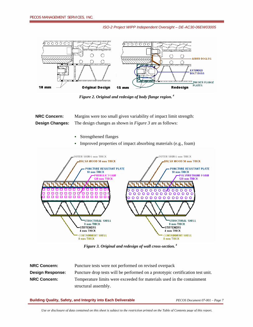
NRC Concern: Non-linear analysis showed yielding in the seal region. Design Changes: As shown in Figure 2, the seal region design changes are as follows:
Thickened inner and outer body flange by 50 percent Thickened outer flange plate by 25 percent Extended bolting bosses through body flange Added “dogleg” to radial rib Conduct full-scale impact test and demonstrate leak tightness
PECOS MANAGEMENT SERVICES, INC.
ISO-2 Project WIPP Independent Oversight – DE-AC30-06EW03005
Building Quality, Safety, and Integrity into Each Deliverable PECOS Document 07-001 – Page 7
Use or disclosure of data contained on this sheet is subject to the restriction printed on the Table of Contents page of this report.
Figure 2. Original and redesign of body flange region. 4
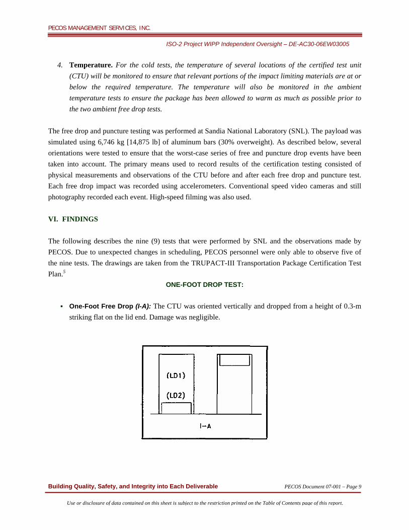
NRC Concern: Margins were too small given variability of impact limit strength: Design Changes: The design changes as shown in Figure 3 are as follows:
Strengthened flanges Improved properties of impact absorbing materials (e.g., foam)
Figure 3. Original and redesign of wall cross-section. 4
NRC Concern: Puncture tests were not performed on revised overpack Design Response: Puncture drop tests will be performed on a prototypic certification test unit. NRC Concern: Temperature limits were exceeded for materials used in the containment structural assembly.

PECOS MANAGEMENT SERVICES, INC.
ISO-2 Project WIPP Independent Oversight – DE-AC30-06EW03005
Building Quality, Safety, and Integrity into Each Deliverable PECOS Document 07-001 – Page 8
Use or disclosure of data contained on this sheet is subject to the restriction printed on the Table of Contents page of this report.
Design Changes Included:
Refined thermal analysis using finer mesh Changed from phenolic foam to polyurethane foam
V. TESTING The TRUPACT-III Transportation Package Certification Test Plan5 states, “There are two primary objectives for the certification test program.” They are:
To demonstrate that after a worst-case series of free drop and puncture events, the package containment is leak-tight.
To further demonstrate that no deformations will be incurred that would lead to failure of the containment under the subsequent HAC fire event.
The test program was conducted according to the following protocol. The licensing basis for the TRUPACT-III package will be primarily a demonstration by test as stated in the TRUPACT-III Transportation Package Certification Test Plan.5 The following measurements must be taken to support this demonstration:
1. Helium Leakage Rate Testing. A helium leakage rate test of the containment seal, per American National Standard Institute, Inc. (ANSI) N14.5 will be performed after closing the package and prior to opening the package. At intermediate points in the test program, helium leakage rate testing or the application of a hard vacuum may be employed as a check. At the conclusion of all testing, the vent/sampling port and containment boundary will also be helium leakage rate tested at or very slightly above atmospheric pressure. The acceptance criterion is leak-tight, or 1 x 10⁻⁷ atm-cc/sec, air.
2. Measurements of the crushed overpack. Detailed photographs or hand sketches of the free drop and puncture damage, including length of any split weld seams, will be created.
3. Accelerations of the free drop impacts. Several accelerometers will be arranged redundantly on the package surface. Signals will be recorded and filtered to capture the rigid body deceleration of impact. The filtering frequency will be chosen after analysis of the raw data.
PECOS MANAGEMENT SERVICES, INC.
ISO-2 Project WIPP Independent Oversight – DE-AC30-06EW03005
Building Quality, Safety, and Integrity into Each Deliverable PECOS Document 07-001 – Page 9
Use or disclosure of data contained on this sheet is subject to the restriction printed on the Table of Contents page of this report.
4. Temperature. For the cold tests, the temperature of several locations of the certified test unit (CTU) will be monitored to ensure that relevant portions of the impact limiting materials are at or below the required temperature. The temperature will also be monitored in the ambient temperature tests to ensure the package has been allowed to warm as much as possible prior to the two ambient free drop tests.
The free drop and puncture testing was performed at Sandia National Laboratory (SNL). The payload was simulated using 6,746 kg [14,875 lb] of aluminum bars (30% overweight). As described below, several orientations were tested to ensure that the worst-case series of free and puncture drop events have been taken into account. The primary means used to record results of the certification testing consisted of physical measurements and observations of the CTU before and after each free drop and puncture test. Each free drop impact was recorded using accelerometers. Conventional speed video cameras and still photography recorded each event. High-speed filming was also used. VI. FINDINGS The following describes the nine (9) tests that were performed by SNL and the observations made by PECOS. Due to unexpected changes in scheduling, PECOS personnel were only able to observe five of the nine tests. The drawings are taken from the TRUPACT-III Transportation Package Certification Test Plan.5
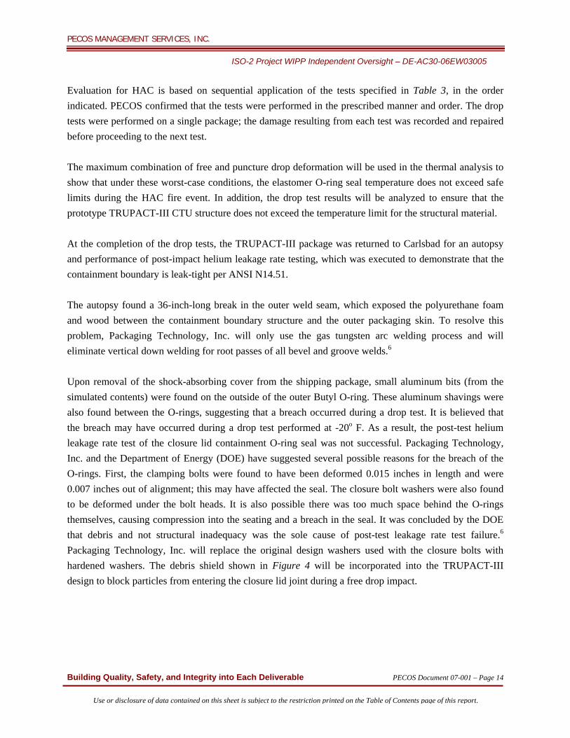
ONE-FOOT DROP TEST:
One-Foot Free Drop (I-A): The CTU was oriented vertically and dropped from a height of 0.3-m striking flat on the lid end. Damage was negligible.

PECOS MANAGEMENT SERVICES, INC.
ISO-2 Project WIPP Independent Oversight – DE-AC30-06EW03005
Building Quality, Safety, and Integrity into Each Deliverable PECOS Document 07-001 – Page 10
Use or disclosure of data contained on this sheet is subject to the restriction printed on the Table of Contents page of this report.
THIRTY-FOOT DROP TESTS:
Flat End Free Drop (I-A): The CTU was tested in a lid-down orientation under maximum-impact conditions. Resulted in 1.15-inch crush of the shock absorbing cover. Vacuum test results were acceptable.
Flat Side Free Drop (II-A): The CTU was dropped in the side orientation, with the impact surface horizontal under maximum-impact conditions. Dr. Jerry Fox, Director, ISO-2 Project Director, observed the test and reported that it was performed in accordance with the Draft Certification Test Plan. The CTU was chilled to a temperature of -20o F. Inspection of the cask after the drop showed an estimated 12 inch tear along a weld on the outside skin at the bottom leading up from the plane of contact. There were a few other very small indications of damage to the outside skin. The vacuum test results were acceptable, and there was negligible crush damage to the CTU.

PECOS MANAGEMENT SERVICES, INC.
ISO-2 Project WIPP Independent Oversight – DE-AC30-06EW03005
Building Quality, Safety, and Integrity into Each Deliverable PECOS Document 07-001 – Page 11
Use or disclosure of data contained on this sheet is subject to the restriction printed on the Table of Contents page of this report.
Side Angle Free Drop (II-B): The CTU was tested in the side-edge orientation. To obtain maximum deformation, the test was performed at ambient temperatures with results extrapolated to maximum temperatures by analysis. Julie Archuleta, PECOS Staff Engineer, observed the test and reported that it was performed in accordance with the Draft Certification Test Plan. The CTU bounced several times and then tilted onto its side. This resulted in a 12-inch-wide dent; the vacuum was not tested.
Center of Gravity (CG) Over Corner (I-D): The CTU was tested in a lid-down, CG over corner orientation at ambient temperature. Vicente Rojas, PECOS Staff Engineer, observed the test and reported that it was performed in accordance with the Draft Certification Test Plan. The CTU sustained a crushed corner, and a weld used to repair a 12-inch-long gash sustained during the flat side free drop test failed. The CTU did not pass the vacuum test.

PECOS MANAGEMENT SERVICES, INC.
ISO-2 Project WIPP Independent Oversight – DE-AC30-06EW03005
Building Quality, Safety, and Integrity into Each Deliverable PECOS Document 07-001 – Page 12
Use or disclosure of data contained on this sheet is subject to the restriction printed on the Table of Contents page of this report.
PUNCTURE TESTS:
Puncture on the Side (III-A): In this orientation, the bar axis was aimed through the CG of the package, and was oriented at 70o to the package surface (or 20o off the normal). The puncture took place on the side of the package that experienced the flat side free drop impact. The side sustained minor damage with no breach of containment.
Puncture on the Overpack Cover (III-B): In this orientation, the bar axis was aimed through the
CG of the package, at an angle that was as oblique as possible considering the geometry of the overpack-covert octagonal recess. The impact point was on the recessed octagonal surface. This puncture challenged the puncture-resistant plate near its edge. The test resulted in minor damage with no breach of the puncture-resistant plate.

PECOS MANAGEMENT SERVICES, INC.
ISO-2 Project WIPP Independent Oversight – DE-AC30-06EW03005
Building Quality, Safety, and Integrity into Each Deliverable PECOS Document 07-001 – Page 13
Use or disclosure of data contained on this sheet is subject to the restriction printed on the Table of Contents page of this report.
Puncture on the CG-over-Corner Drop Damage (III-G): The damage from the CG over-corner free drop was expected to result in the greatest crush distance. Therefore, this puncture could have penetrated deeper than any other orientation. Vicente Rojas, PECOS Staff Engineer, observed the test and reported that it was performed in accordance with the Draft Certification Test Plan. A stationary 6-inch solid mild steel punch penetrated 5 inches into the outer skin of the package.
Puncture on the Side-Edge Drop Damage (III-H): The side-edge drop damage could result in
deformation in the vicinity of the thermal shield. This test resulted in a 4-inch penetration depth, with minor damage to the CTU.
PECOS MANAGEMENT SERVICES, INC.
ISO-2 Project WIPP Independent Oversight – DE-AC30-06EW03005
Building Quality, Safety, and Integrity into Each Deliverable PECOS Document 07-001 – Page 14
Use or disclosure of data contained on this sheet is subject to the restriction printed on the Table of Contents page of this report.
Evaluation for HAC is based on sequential application of the tests specified in Table 3, in the order indicated. PECOS confirmed that the tests were performed in the prescribed manner and order. The drop tests were performed on a single package; the damage resulting from each test was recorded and repaired before proceeding to the next test. The maximum combination of free and puncture drop deformation will be used in the thermal analysis to show that under these worst-case conditions, the elastomer O-ring seal temperature does not exceed safe limits during the HAC fire event. In addition, the drop test results will be analyzed to ensure that the prototype TRUPACT-III CTU structure does not exceed the temperature limit for the structural material. At the completion of the drop tests, the TRUPACT-III package was returned to Carlsbad for an autopsy and performance of post-impact helium leakage rate testing, which was executed to demonstrate that the containment boundary is leak-tight per ANSI N14.51. The autopsy found a 36-inch-long break in the outer weld seam, which exposed the polyurethane foam and wood between the containment boundary structure and the outer packaging skin. To resolve this problem, Packaging Technology, Inc. will only use the gas tungsten arc welding process and will eliminate vertical down welding for root passes of all bevel and groove welds.6 Upon removal of the shock-absorbing cover from the shipping package, small aluminum bits (from the simulated contents) were found on the outside of the outer Butyl O-ring. These aluminum shavings were also found between the O-rings, suggesting that a breach occurred during a drop test. It is believed that the breach may have occurred during a drop test performed at -20o F. As a result, the post-test helium leakage rate test of the closure lid containment O-ring seal was not successful. Packaging Technology, Inc. and the Department of Energy (DOE) have suggested several possible reasons for the breach of the O-rings. First, the clamping bolts were found to have been deformed 0.015 inches in length and were 0.007 inches out of alignment; this may have affected the seal. The closure bolt washers were also found to be deformed under the bolt heads. It is also possible there was too much space behind the O-rings themselves, causing compression into the seating and a breach in the seal. It was concluded by the DOE that debris and not structural inadequacy was the sole cause of post-test leakage rate test failure.6 Packaging Technology, Inc. will replace the original design washers used with the closure bolts with hardened washers. The debris shield shown in Figure 4 will be incorporated into the TRUPACT-III design to block particles from entering the closure lid joint during a free drop impact.

PECOS MANAGEMENT SERVICES, INC.
ISO-2 Project WIPP Independent Oversight – DE-AC30-06EW03005
Building Quality, Safety, and Integrity into Each Deliverable PECOS Document 07-001 – Page 15
Use or disclosure of data contained on this sheet is subject to the restriction printed on the Table of Contents page of this report.
Figure 4. Debris shield design. 6
Four Gas Pressure Rise tests were performed by independent ANSI-certified technicians according to ANSI N14.5-1997,7 leakage rate test standards. This standard states: “One problem with this method is outgassing (the release of gases from the surfaces of the test item when the item is evacuated).” To alleviate this problem, the inner containment vessel was evacuated for three weeks prior to testing to ensure accuracy of test results. After being evacuated, the TRUPACT-III was pressurized to 14.7 pounds force/square inch (psi) for each test, and the pressure was monitored for 10 hours to observe any changes. The TRUPACT-III passed these four leakage rate tests. The required thermal analysis and the HAC fire event computer simulation have not been made available at this time. Packaging Technology, Inc. and DOE plan to demonstrate the effectiveness of the debris shield by discussion and analysis. The seal design will be tested using either the bench seal test or full scale testing. The intent of Packaging Technology, Inc. is to request that design changes be taken into consideration without additional retesting of a prototype. TRUPACT-III was intended to have an inner standard large box (SLB) to contain the TRU waste; the SLB was not used during testing and may have affected the results of the drop tests.
PECOS MANAGEMENT SERVICES, INC.
ISO-2 Project WIPP Independent Oversight – DE-AC30-06EW03005
Building Quality, Safety, and Integrity into Each Deliverable PECOS Document 07-001 – Page 16
Use or disclosure of data contained on this sheet is subject to the restriction printed on the Table of Contents page of this report.
VII. CONCLUSIONS PECOS concludes that Packaging Technology, Inc. has made appropriate design changes to address the design faults exposed by the drop tests. VIII. RECOMMENDATIONS Given the issues related to the drop tests, it is the recommendation of PECOS that the TRUPACT-III design should be modified, and that the redesigned TRUPACT-III should be retested as required by 10 CFR 71. It is also recommended that DOE incorporate the SLB in any additional testing, as it was intended to be included in TRUPACT-III shipments.
REPORT PREPARED BY: Julie D. Archuleta, Staff Engineer REVIEWERS: Jerry V. Fox, PhD, PE, Director, ISO-2 Project Vicente Rojas, PE, Staff Engineer Christopher M. Timm, PE, Quality Assurance Manager REFERENCES: 1. 10CFR71.43 – Packing and Transportation of Radioactive Material. General standards for all
packages. US Nuclear Regulatory Commission (October 2006), Washington DC. Code of Federal Regulations Title 10. Available for viewing and downloading via the website http://www.nrc.gov
2. 10CFR71.71 – Packing and Transportation of Radioactive Material. Normal conditions of transport.
US Nuclear Regulatory Commission (October 2006), Washington DC. Code of Federal Regulations Title 10. Available for viewing and downloading via the website http://www.nrc.gov
3. 10CFR71.73 – Packing and Transportation of Radioactive Material. Hypothetical accident
conditions. US Nuclear Regulatory Commission (October 2006), Washington DC. Code of Federal Regulations Title 10. Available for viewing and downloading via the website http://www.nrc.gov
PECOS MANAGEMENT SERVICES, INC.
ISO-2 Project WIPP Independent Oversight – DE-AC30-06EW03005
Building Quality, Safety, and Integrity into Each Deliverable PECOS Document 07-001 – Page 17
Use or disclosure of data contained on this sheet is subject to the restriction printed on the Table of Contents page of this report.
4. “Status of the TRUPACT-III Application.” Presented to the Western Governor’s Association (WGA) WIPP Transportation Advisory Group by Earl Easton, Spent Fuel Project Office, US Nuclear Regulatory Commission, (May 5, 2005). Available for viewing and downloading via the website http://www.nrc.gov
5. “Draft Certification Test Plan, TRUPACT-I11 Package.” Gary L. Clark, P.E. Packaging Technology,
Inc. US Nuclear Regulatory Commission, Docket No. 71-9305 Available for viewing and downloading via the website http://www.nrc.gov.
6. “TRUPACT-III Package Certification Test Results, A Presentation to the US Nuclear Regulatory
Commission.” Gary L. Clark, P.E. Packaging Technology, Inc. US Nuclear Regulatory Commission, Docket No. 71-9305. (March 29, 2007).
7. ANSI N14.5-1997 -“American National Standard for Radioactive Materials – Leakage Tests on
Packages for Shipment.” American National Standards Institute, Inc. (February 5, 1998), New York, NY.
BIBLIOGRAPHY “NRC INFORMATION NOTICE 97-57: LEAK TESTING OF PACKAGING USED IN THE TRANSPORT OF RADIOACTIVE MATERIAL.” UNITED STATES NUCLEAR REGULATORY COMMISSION, OFFICE OF NUCLEAR MATERIAL SAFETY AND SAFEGUARDS, WASHINGTON, D.C., (July 30, 1997). Available for viewing and downloading via the website http://www.nrc.gov/reading-rm/doc-collections/gen-comm/info-notices/1997/in97057.html “Polyurethane Foam Material Specification for the TRUPACT-III Package.” Packaging Technology, Inc., Specification No. FP-043, Project No. 51199 “Report to Western Governors on the Status of the WIPP Transportation Safety Program.” Developed Cooperatively Through The Western Governors’ Association WIPP Transportation Technical Advisory Group, (June 2004). Available for viewing and downloading via the website http://www.westgov.org/wga/initiatives/wipp/govs-rpt6-04.pdf “Status of the TRUPACT-III and ARROW-PAK Applications.” Presented to the Western Governor’s Association (WGA) WIPP Transportation Advisory Group by Earl Easton, Spent Fuel Project Office, US Nuclear Regulatory Commission, (October 5, 2005). Available for viewing and downloading via the website http://www.nrc.gov

PECOS MANAGEMENT SERVICES, INC.
ISO-2 Project WIPP Independent Oversight – DE-AC30-06EW03005
Building Quality, Safety, and Integrity into Each Deliverable PECOS Document 07-001 – Page 18
Use or disclosure of data contained on this sheet is subject to the restriction printed on the Table of Contents page of this report.
“TRUPACT-III Shipment of Oversized Box Inventory of CH TRU Waste.” J. Biedscheid, M. Devarakonda, G. F. Lunsford. WM’04 Conference, February 29 – March 4, 2004, Tucson, AZ. Available for viewing and downloading via the website http://www.westgov.org/wga/initiatives/wipp/TrupactIII.pdf “TRUPACT-III Transport Package, a Presentation to the US Nuclear Regulatory Commission.” Packaging Technology, Inc., US Nuclear Regulatory Commission, Docket 71-9305. Available for viewing and downloading via the website http://www.nrc.gov “WIPP Transportation Safety Program Implementation Guide.” Prepared Cooperatively by: Western Governors’ Association, WIPP Transportation, Technical Advisory Group, U.S. Department of Energy Carlsbad Field Office, (December 2003). Available for viewing and downloading via the website http://www.westgov.org/wga/initiatives/wipp/wipp-pig03.pdf