fdn eng-part 1
DESCRIPTION
foundation designTRANSCRIPT

CE646 Foundation Engineering
Bearing capacity, Shallow foundations; Mats and Rafts, Flexible design, Deep foundations; Piles and piers, Machine foundations, Foundations under difficult ground conditions, Provisional structures, Construction techniques, Improvement of existing foundations.
L.C.Kurukulasuriya
Bearing capacity
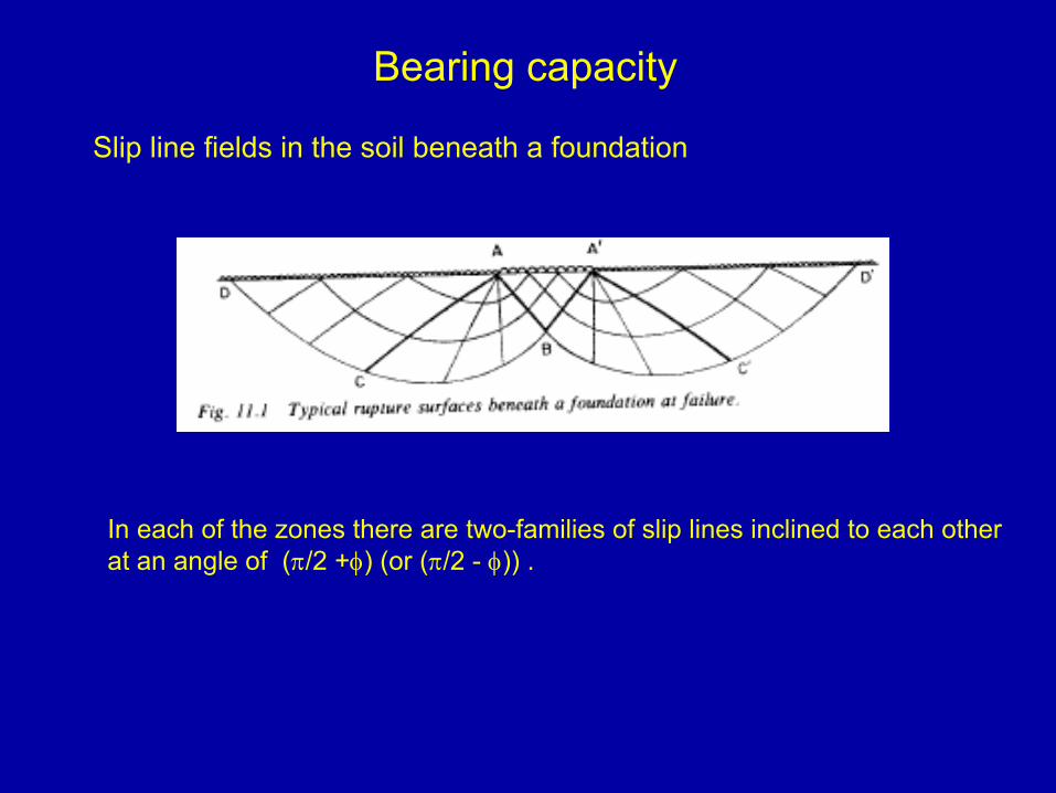
Slip line fields in the soil beneath a foundation
In each of the zones there are two-families of slip lines inclined to each otherat an angle of (π/2 +φ) (or (π/2 - φ)) .
The bearing capacity of a foundation
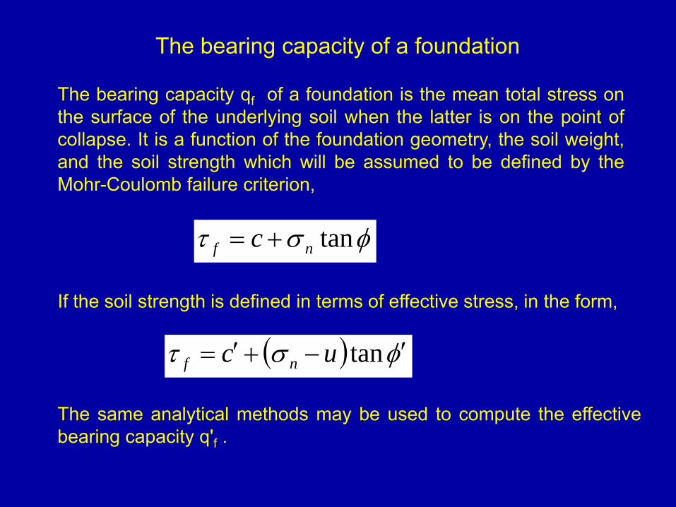
The bearing capacity qf of a foundation is the mean total stress onthe surface of the underlying soil when the latter is on the point ofcollapse. It is a function of the foundation geometry, the soil weight,and the soil strength which will be assumed to be defined by theMohr-Coulomb failure criterion,
φστ tannf c +=
If the soil strength is defined in terms of effective stress, in the form,
( ) φστ ′−+′= tanuc nf
The same analytical methods may be used to compute the effectivebearing capacity qʹf .

Plastic Theory
In plastic methods of analysis, soil is assumed to be an ideal rigid plastic material.
Collapse load or the bearing capacity of such a material is unique.
σ
ε
σy
0
There are two important theorems for ideal plastic material.
These are called limit theorems.
•Lower bound theorem
If a stress distribution is found which is in equilibrium satisfying stress boundary conditions everywhere and at the same time does not violate yield criterion, then the body will not collapse under applied loads.
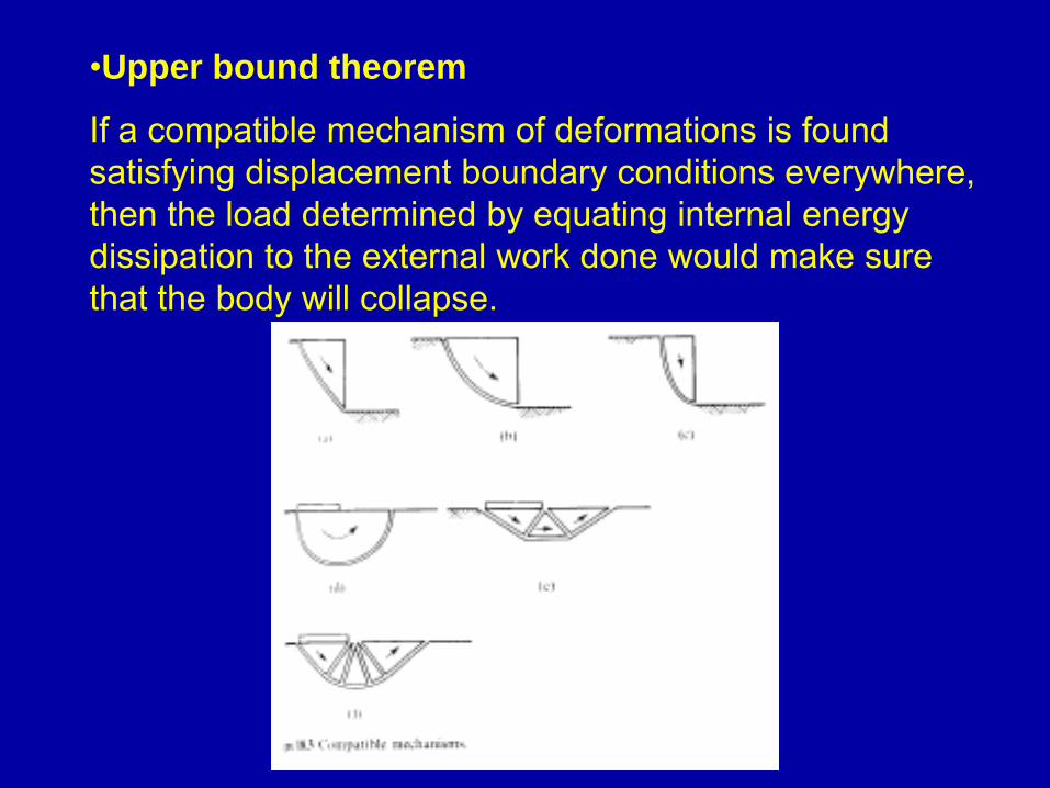
•Upper bound theorem
If a compatible mechanism of deformations is found satisfying displacement boundary conditions everywhere, then the load determined by equating internal energy dissipation to the external work done would make sure that the body will collapse.
Find the lowest upper bound solution and the highest lower bound solution so that the collapse load can be closely bracketed.
Note: All elastic solutions are lower bound solutions.
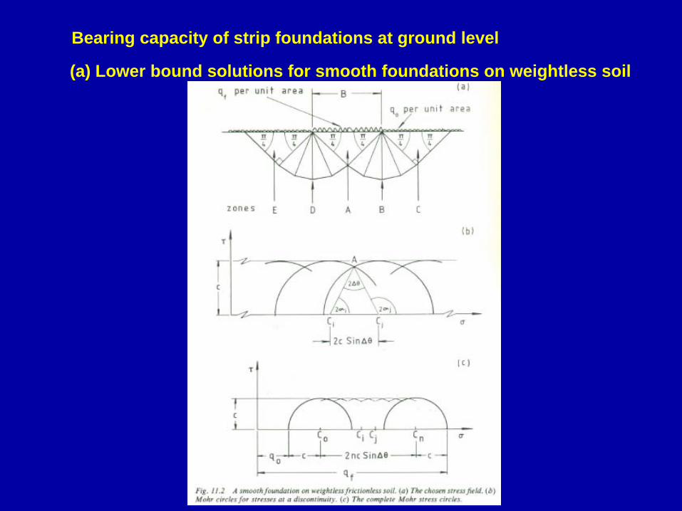
Bearing capacity of strip foundations at ground level
(a) Lower bound solutions for smooth foundations on weightless soil
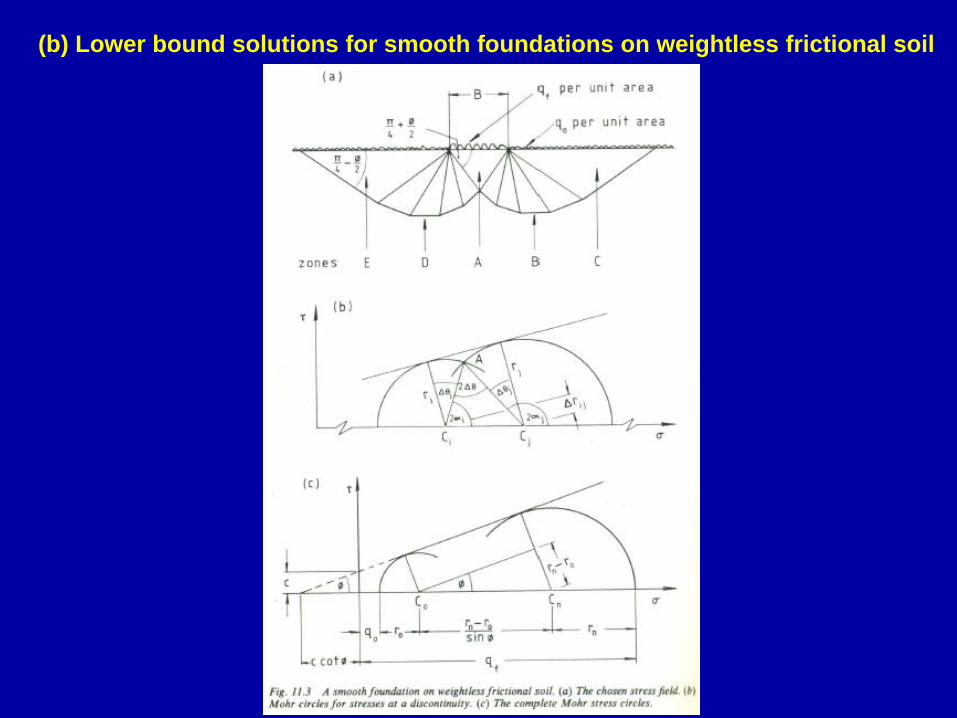
(b) Lower bound solutions for smooth foundations on weightless frictional soil
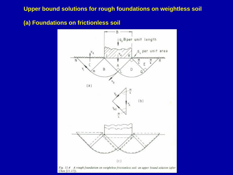
Upper bound solutions for rough foundations on weightless soil
(a) Foundations on frictionless soil
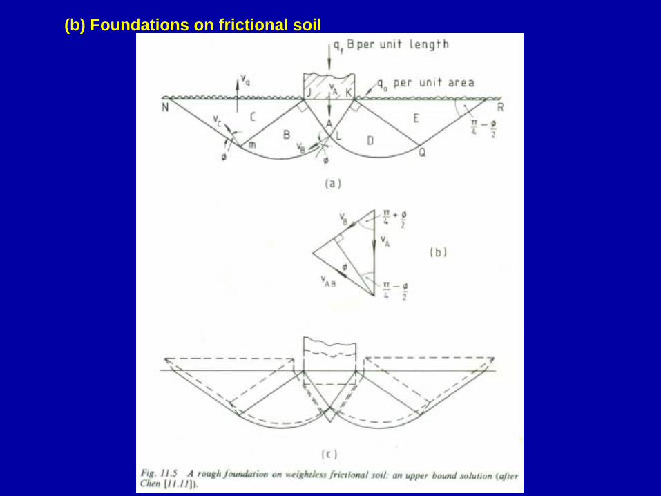
(b) Foundations on frictional soil

1.Locate the site and the position of load. A rough estimate of the foundation load(s) is usually provided by the client.
2. Inspect the site physically for any geological or other evidence that may indicate a potential design problem that will have to be taken into account in the design or to give a design recommendation. Supplement this inspection with any previously obtained soil data.
Shallow foundations
3. Establish the field exploration program and, on the basis of its outcome, supplement by necessary field testing and any laboratory test program.
4. Determine the necessary soil design parameters based on integration of test data, scientific principles, and engineering judgment.
For complex problems, compare the recommended data with published literature or engage another geotechnical consultant to give an outside perspective to the results.
5. Design the foundation using the soil parameters obtained earlier.
The foundation should be economical and be able to be built by the available construction personnel.
Take into account practical construction tolerances and local construction practices. Interact closely with all concerned (client, engineers, architect, contractor) so that the substructure system is not excessively overdesigned and risk is kept within acceptable levels.
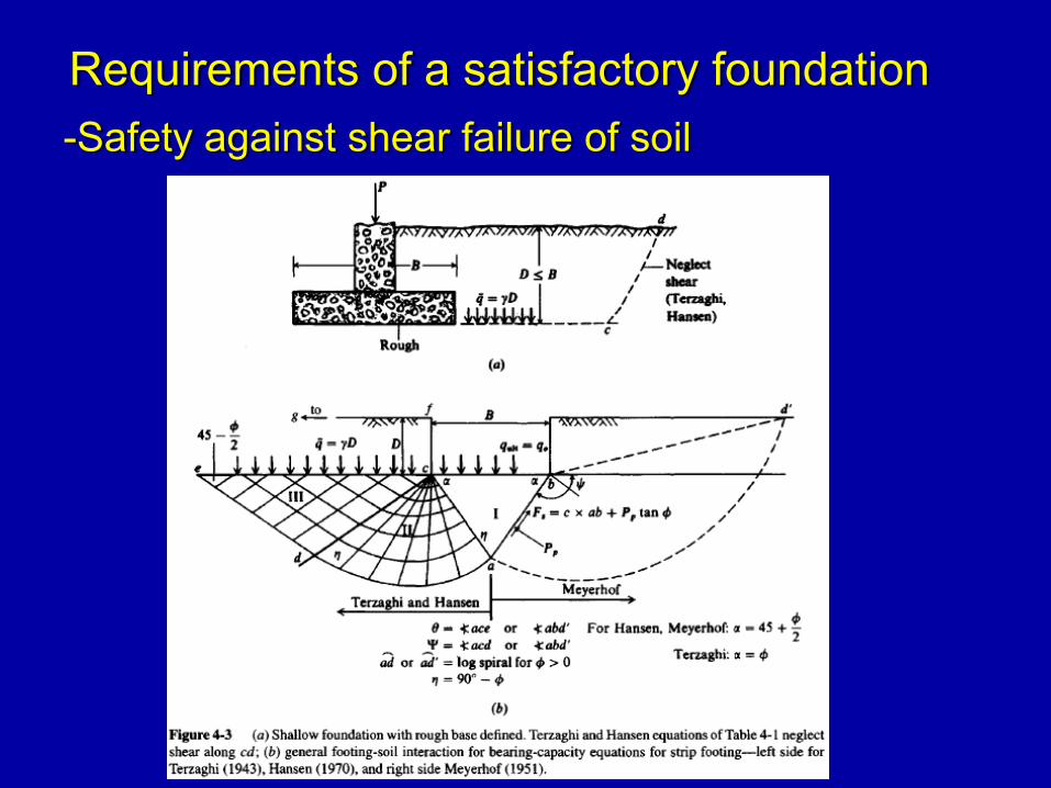
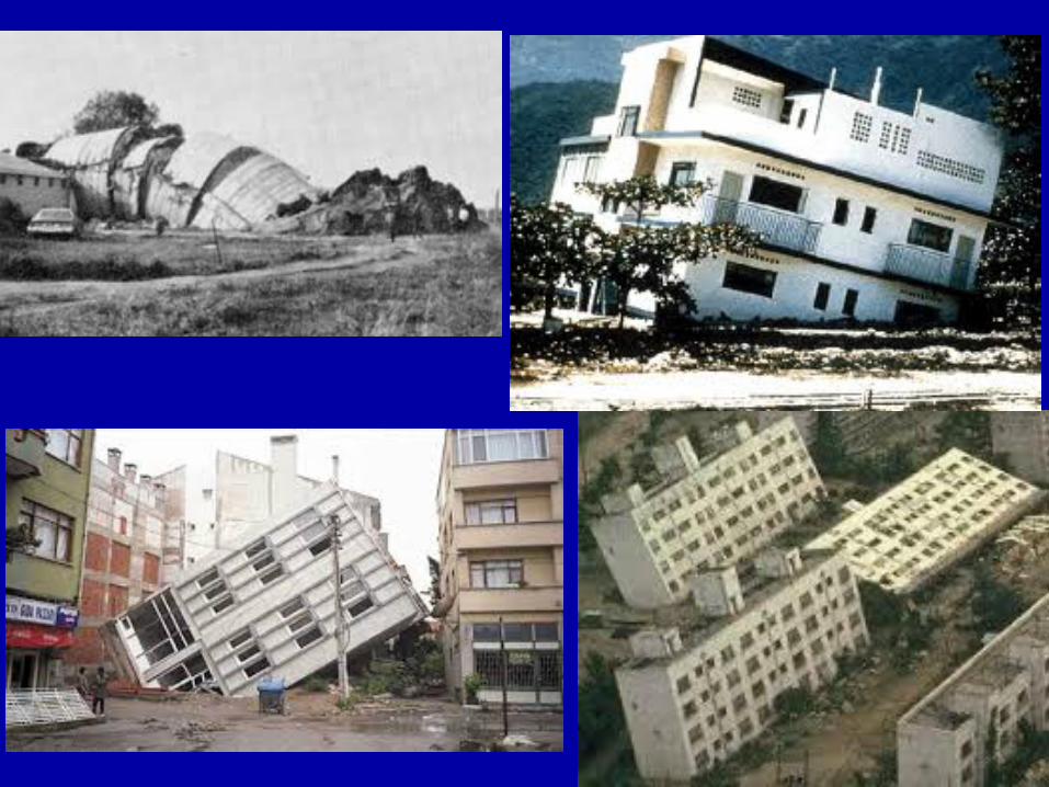
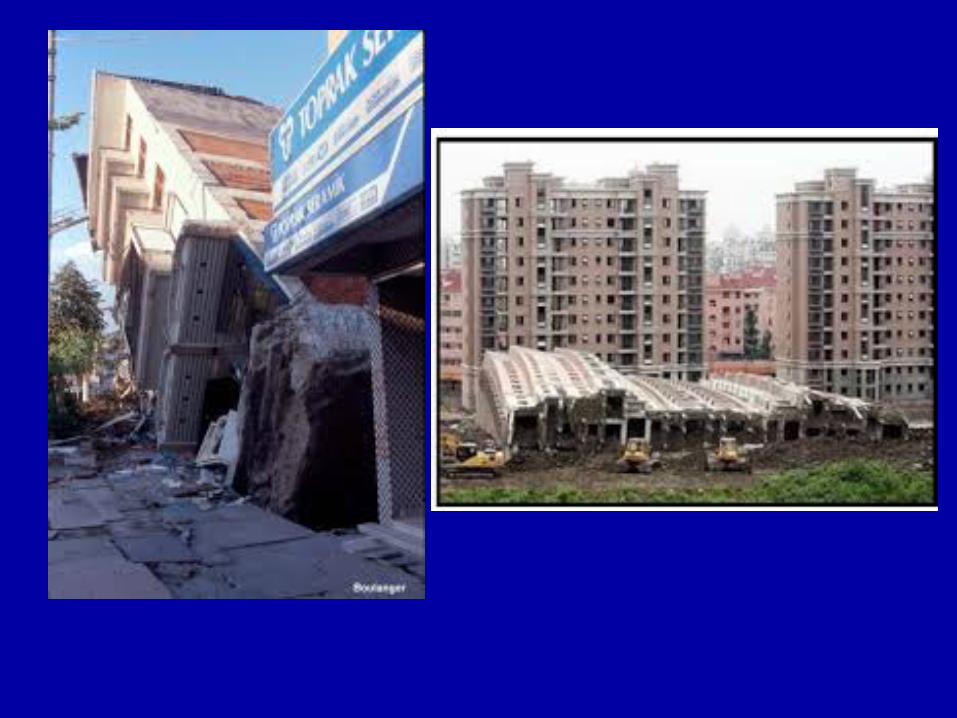
Requirements of a satisfactory foundation-Safety against shear failure of soil
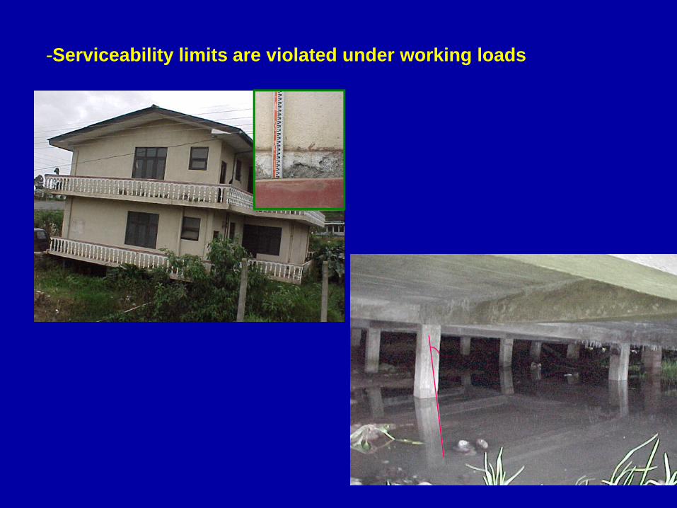
-Serviceability limits are violated under working loads
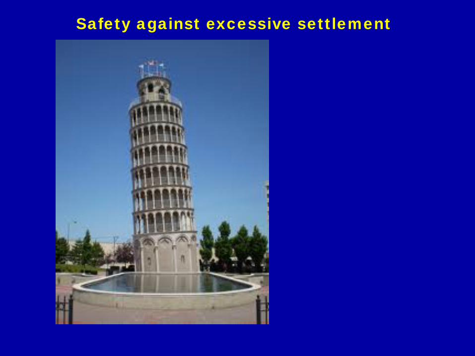
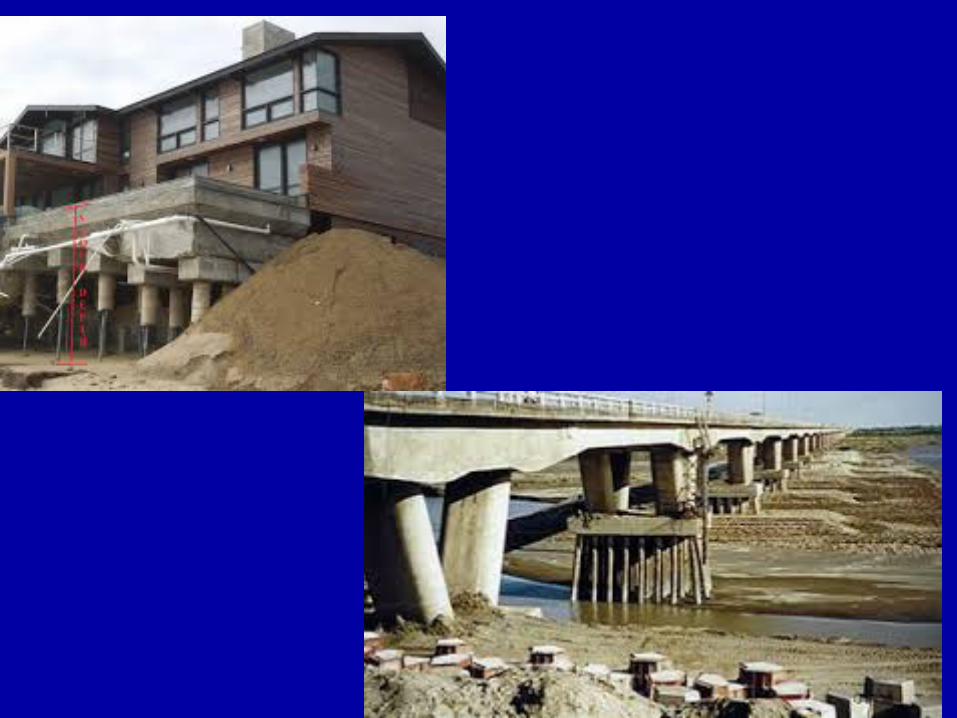
Safety against excessive settlement
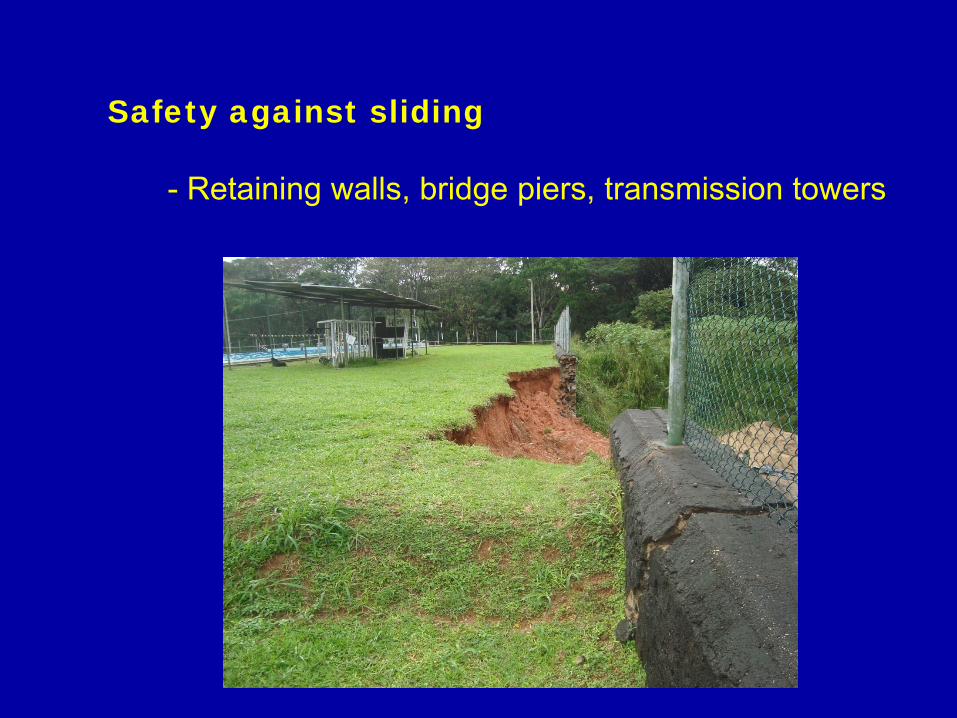
Safety against sliding
- Retaining walls, bridge piers, transmission towers
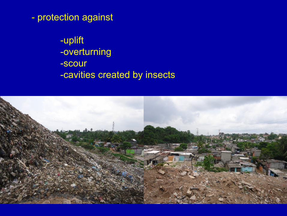
- protection against
-uplift-overturning-scour-cavities created by insects
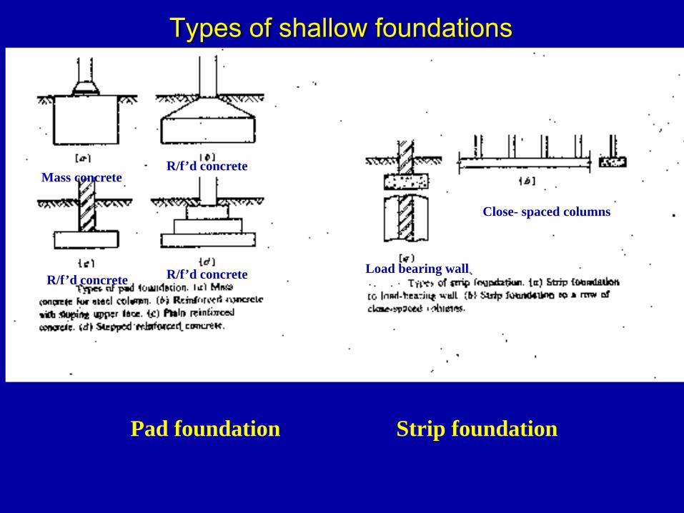
Types of shallow foundations
Mass concreteR/f’d concrete
R/f’d concrete R/f’d concrete
Pad foundation Strip foundation
Load bearing wall
Close- spaced columns
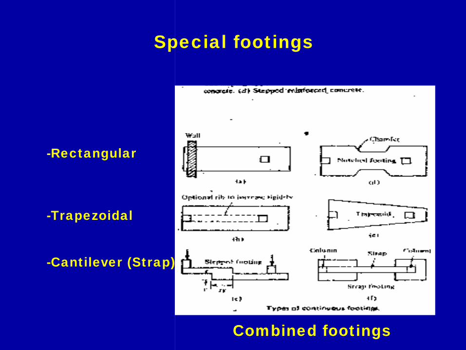
Special footings
-Rectangular
-Trapezoidal
-Cantilever (Strap)
Combined footings
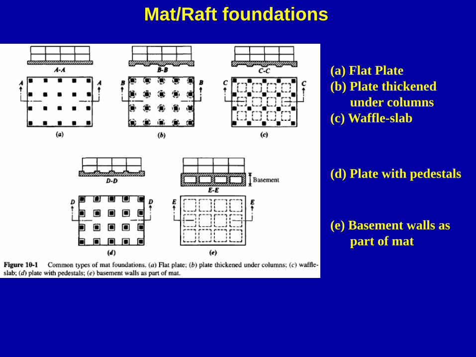
Mat/Raft foundations
Flat plate(a) Flat Plate(b) Plate thickened
under columns(c) Waffle-slab
Two way beam and slab
(d) Plate with pedestals
Cellular
(e) Basement walls as part of mat
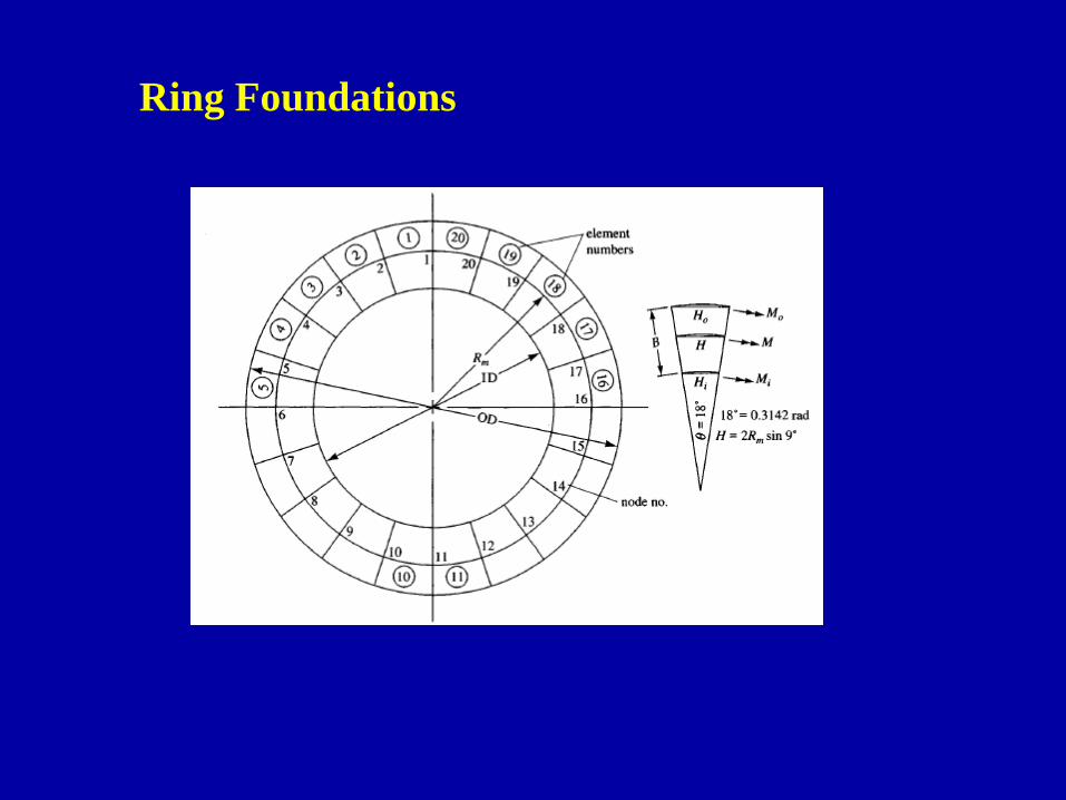
Ring Foundations
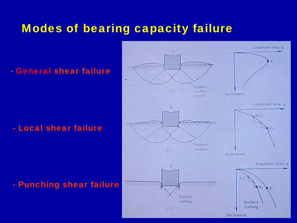
Modes of bearing capacity failure
- General shear failure
- Local shear failure
- Punching shear failure
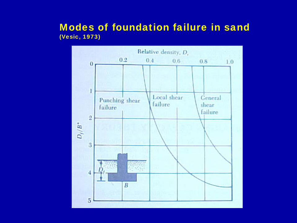
Modes of foundation failure in sand (Vesic, 1973)
Design of foundations
- On clayey soils -either bearing capacity or settlement may govern the design
- the undrained shear strength is usually the controllingfactor as clays are of low permeability and undrained conditions could prevail during loading.
- the bearing capacity will increase with time as the clayis consolidated. At this stage, settlement could governthe design.
- On granular soils
- high permeability will ensure drained conditions.
- applied load will increase both shear stresses and shear strength.
- therefore, the allowable bearing stress in terms of bearing capacity failure is very high.
- as a result, the allowable bearing pressure is determined by consideration of settlements rather than strength.(except in foundations of low width)
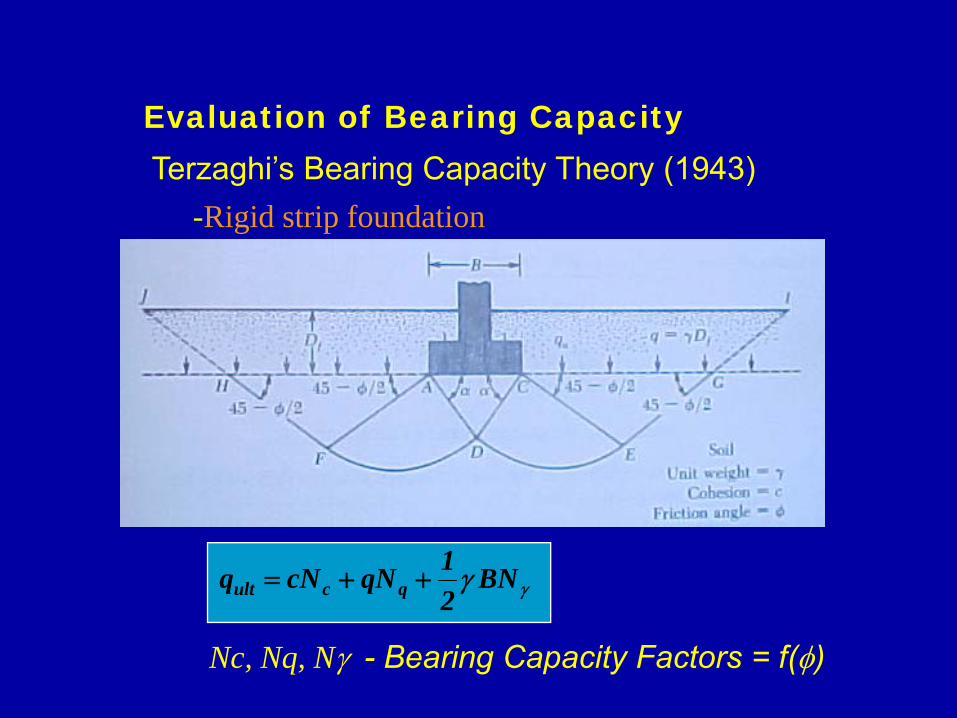
Evaluation of Bearing CapacityTerzaghi’s Bearing Capacity Theory (1943)
γγ BN21qNcNq qcult ++=
-Rigid strip foundation
Nc, Nq, Nγ - Bearing Capacity Factors = f(φ)
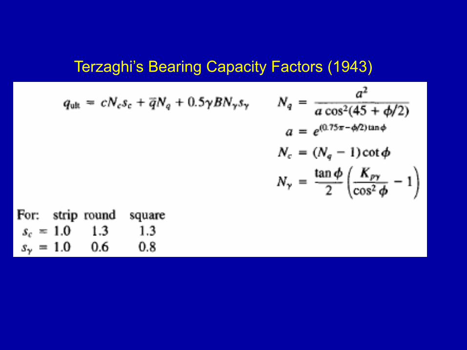
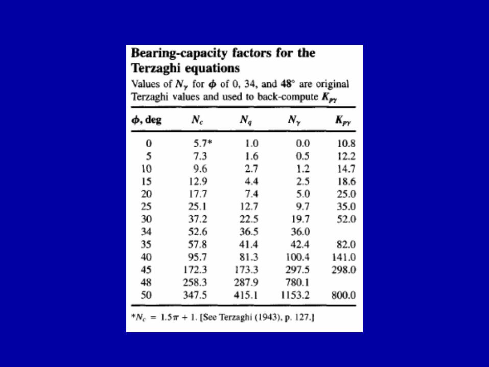
Terzaghi’s Bearing Capacity Factors (1943)
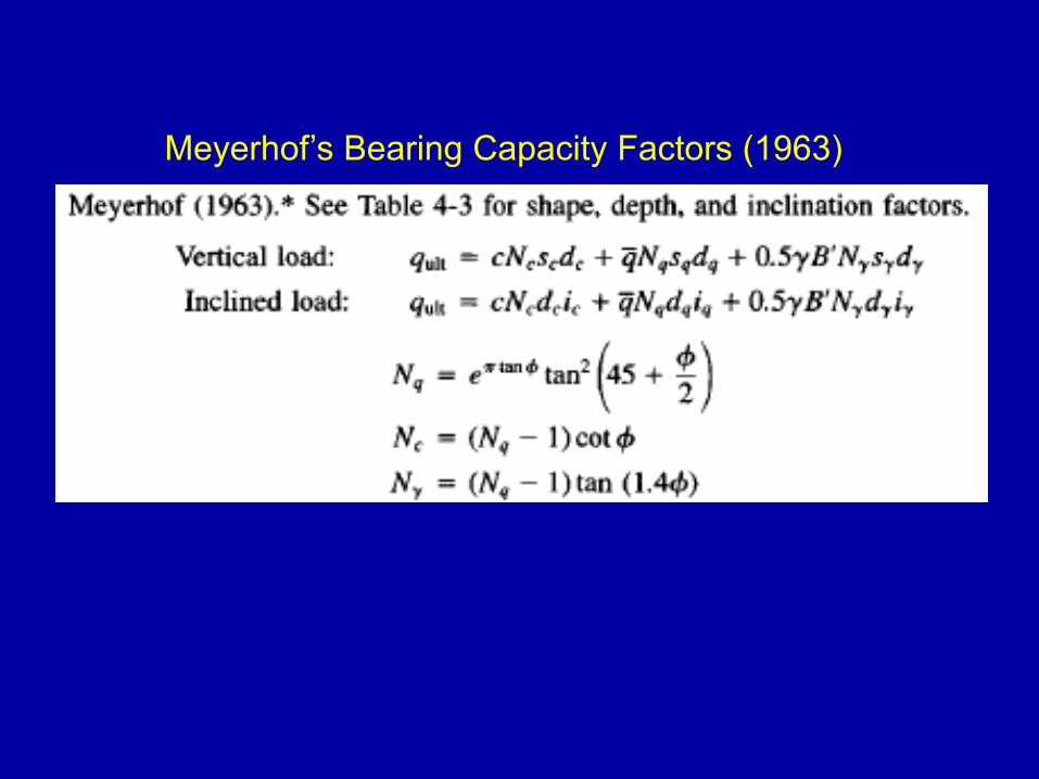
Meyerhof’s Bearing Capacity Factors (1963)
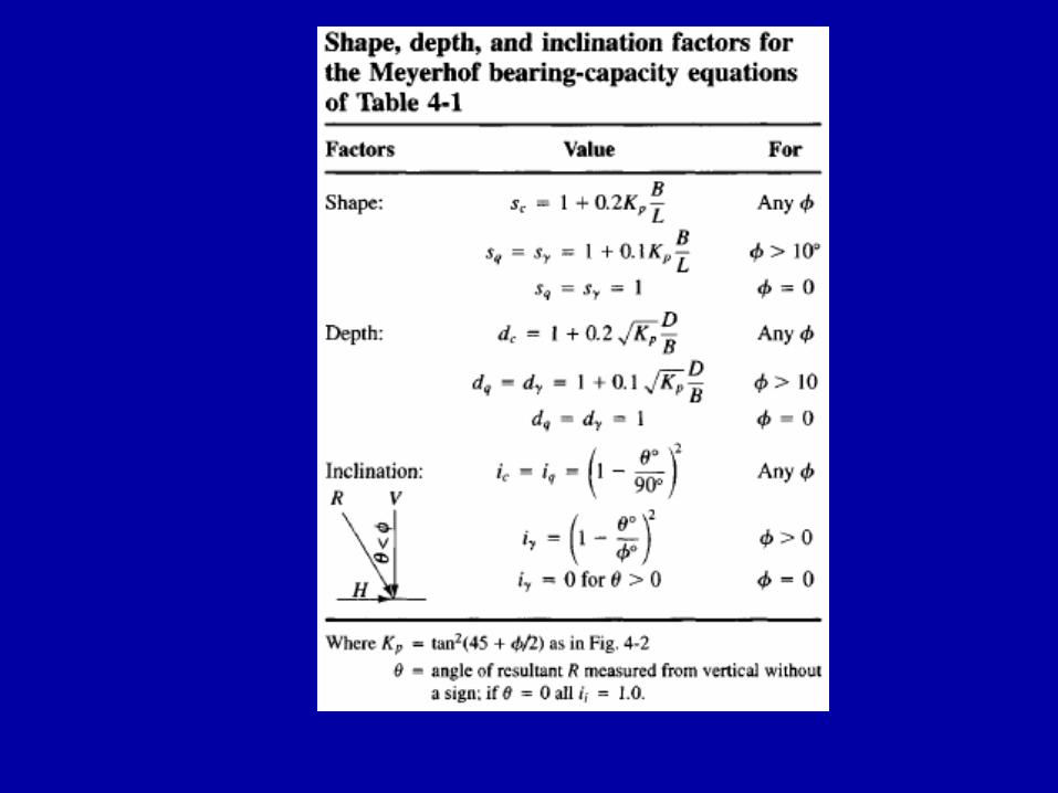
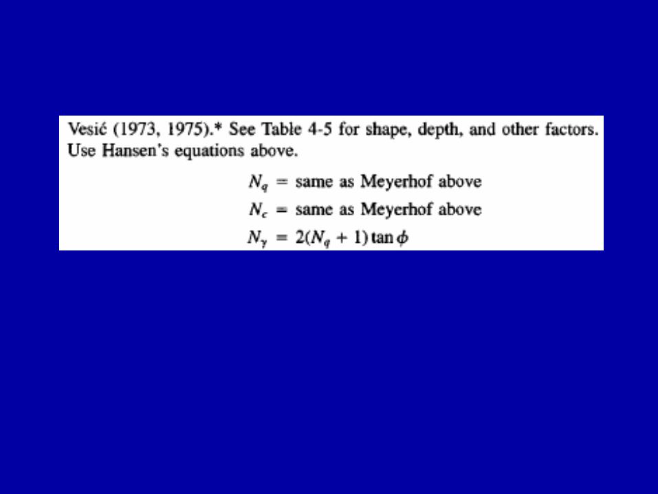
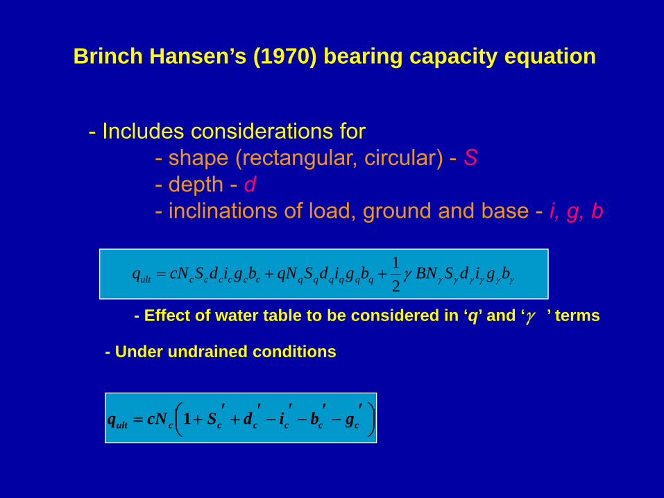
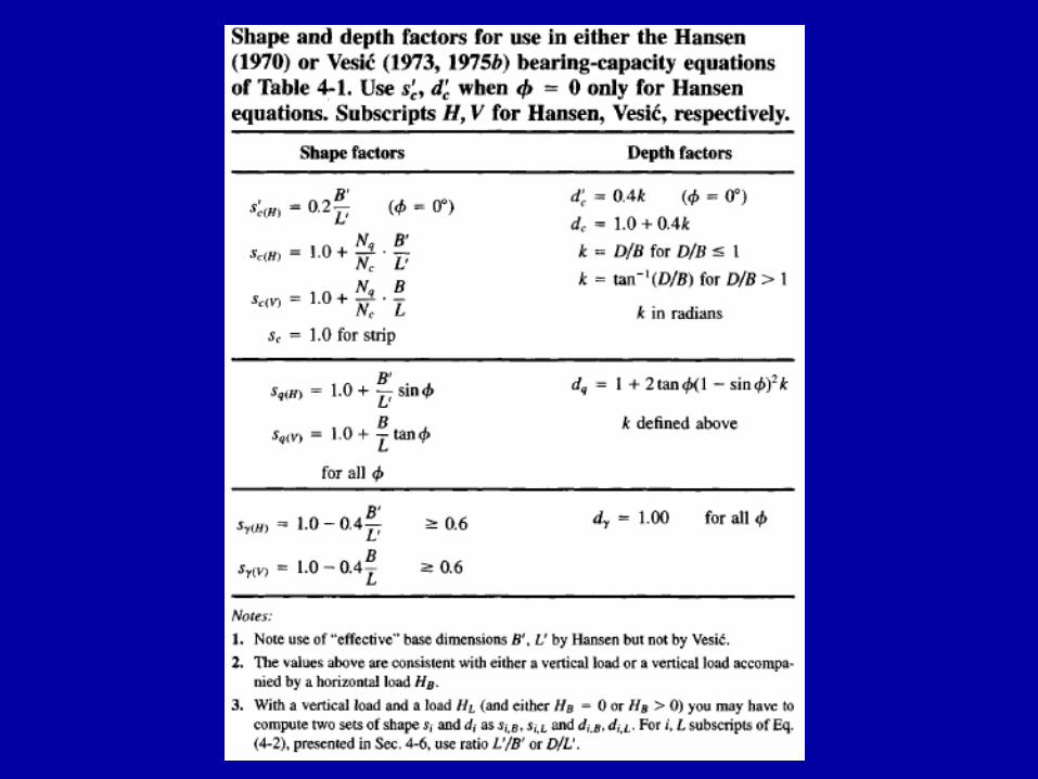
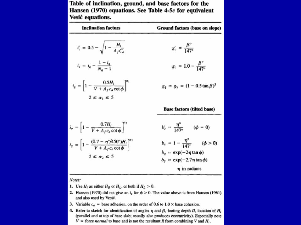
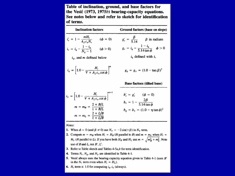
Brinch Hansen’s (1970) bearing capacity equation
- Includes considerations for - shape (rectangular, circular) - S- depth - d- inclinations of load, ground and base - i, g, b
γγγγγγγ bgidSBNbgidSqNbgidScNq qqqqqqccccccult 21
++=
- Under undrained conditions
⎟⎠⎞⎜
⎝⎛ ′−′−′−′+′+= ccccccult gbidScNq 1
- Effect of water table to be considered in ‘q’ and ‘γ ’ terms
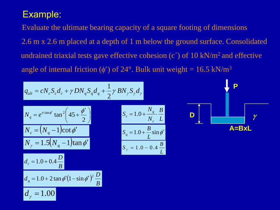
Example: Evaluate the ultimate bearing capacity of a square footing of dimensions
2.6 m x 2.6 m placed at a depth of 1 m below the ground surface. Consolidated
undrained triaxial tests gave effective cohesion (c´) of 10 kN/m2 and effective
angle of internal friction (φ′) of 24°. Bulk unit weight = 16.5 kN/m3
⎟⎠⎞
⎜⎝⎛ ′
+= ′
245tan2tan φφπeNq
( ) φ′−= cot1qc NN
( ) φγ ′−= tan15.1 qNNφ′+= sin0.1
LBSq
LB
NN
Sc
qc ⋅+= 0.1
LBS 4.00.1 −=γ
BDdc 4.00.1 +=
( )BDdq
2sin1tan20.1 φφ ′−′+=
00.1=γd
γγγγγ dSBNdSDNdScNq qqqcccult 21
++=
D
P
A=BxL
γ
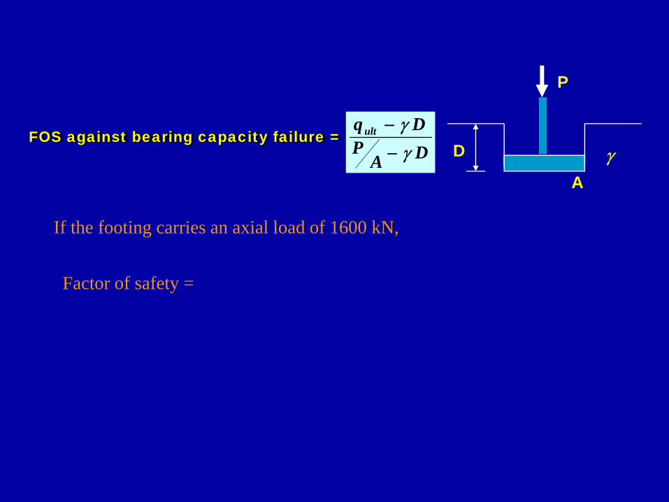
FOS against bearing capacity failure =DA
PDqult
γγ
−
−D
P
Aγ
If the footing carries an axial load of 1600 kN,
Factor of safety =
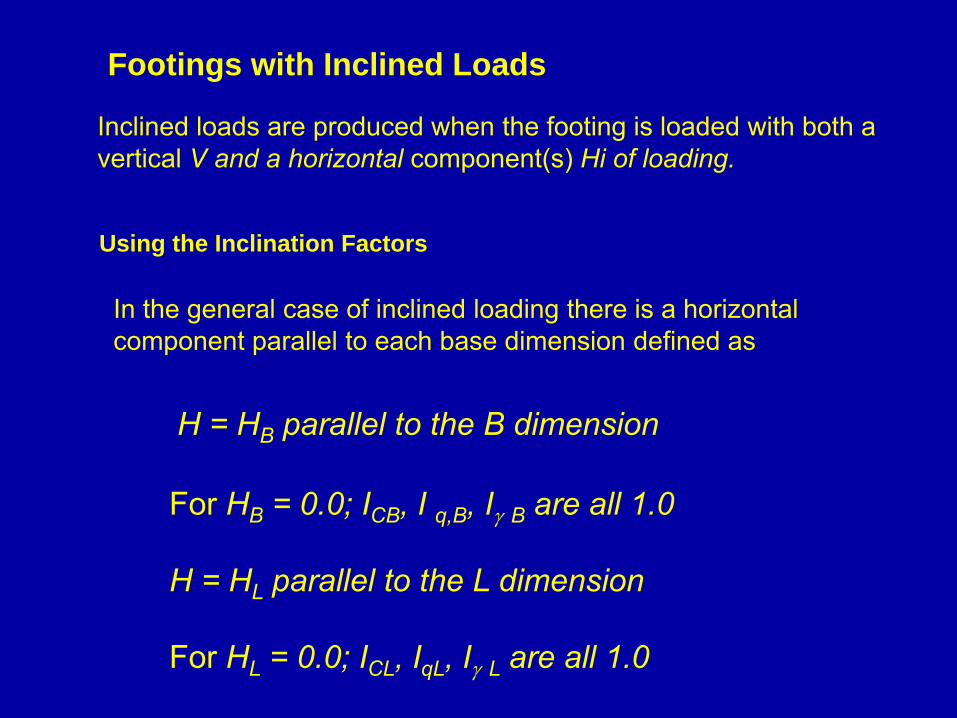
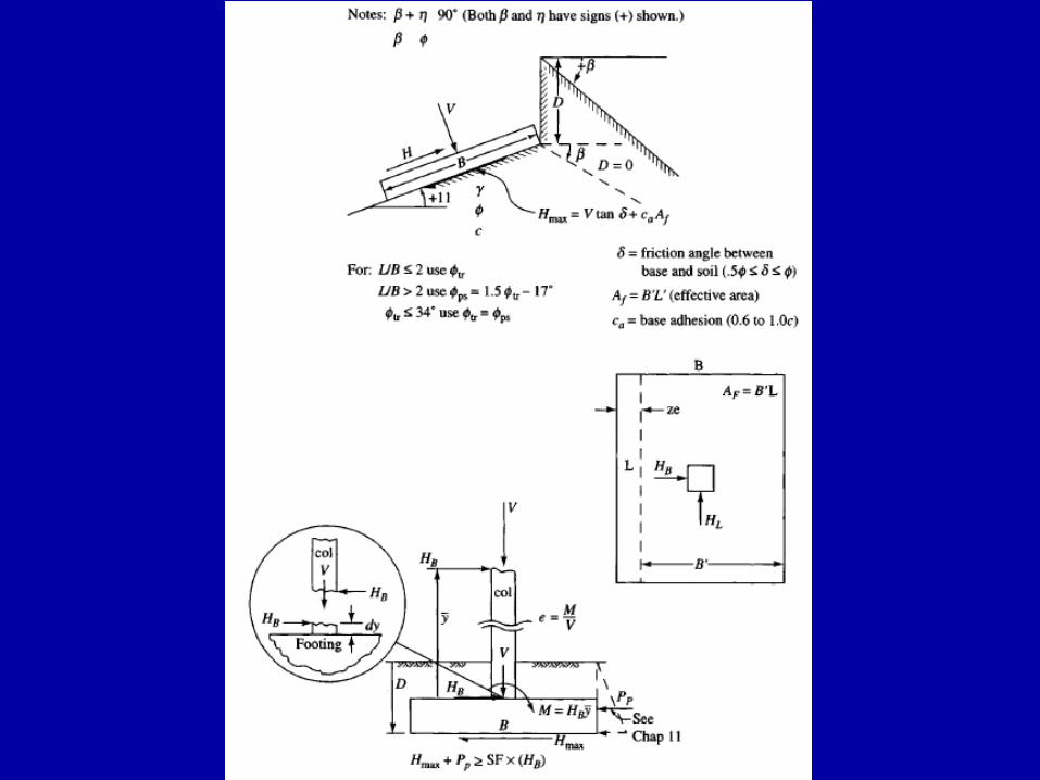
Footings with Inclined Loads
Inclined loads are produced when the footing is loaded with both a vertical V and a horizontal component(s) Hi of loading.
Using the Inclination Factors
In the general case of inclined loading there is a horizontal component parallel to each base dimension defined as
H = HB parallel to the B dimension
For HB = 0.0; ICB, I q,B, Iγ B are all 1.0
H = HL parallel to the L dimension
For HL = 0.0; ICL, IqL, Iγ L are all 1.0
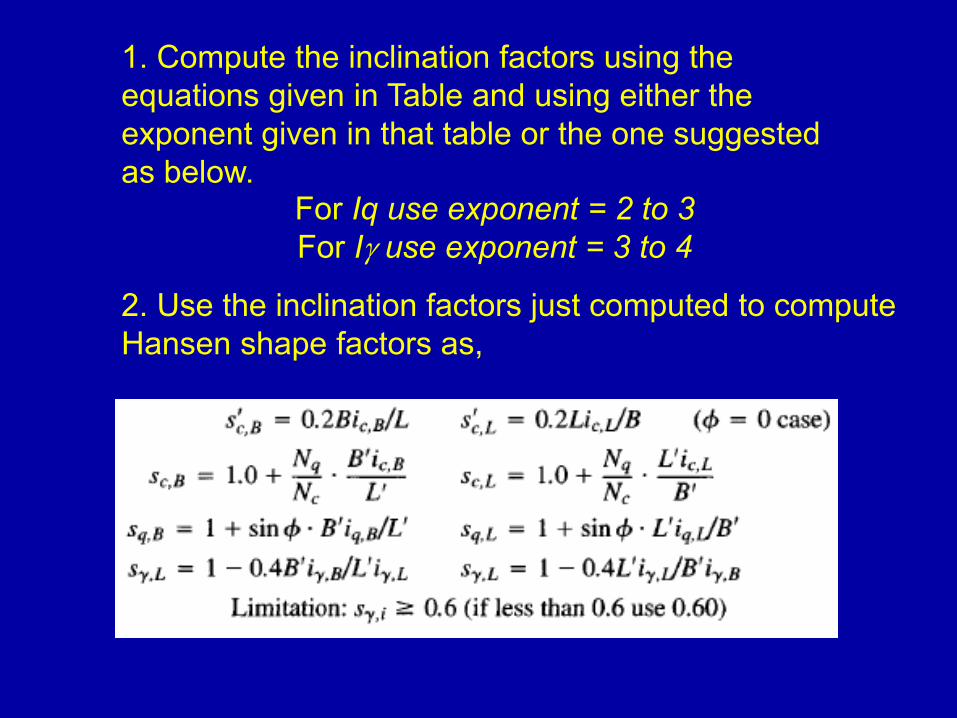
1. Compute the inclination factors using the equations given in Table and using either the exponent given in that table or the one suggested as below.
For Iq use exponent = 2 to 3For Iγ use exponent = 3 to 4
2. Use the inclination factors just computed to compute Hansen shape factors as,
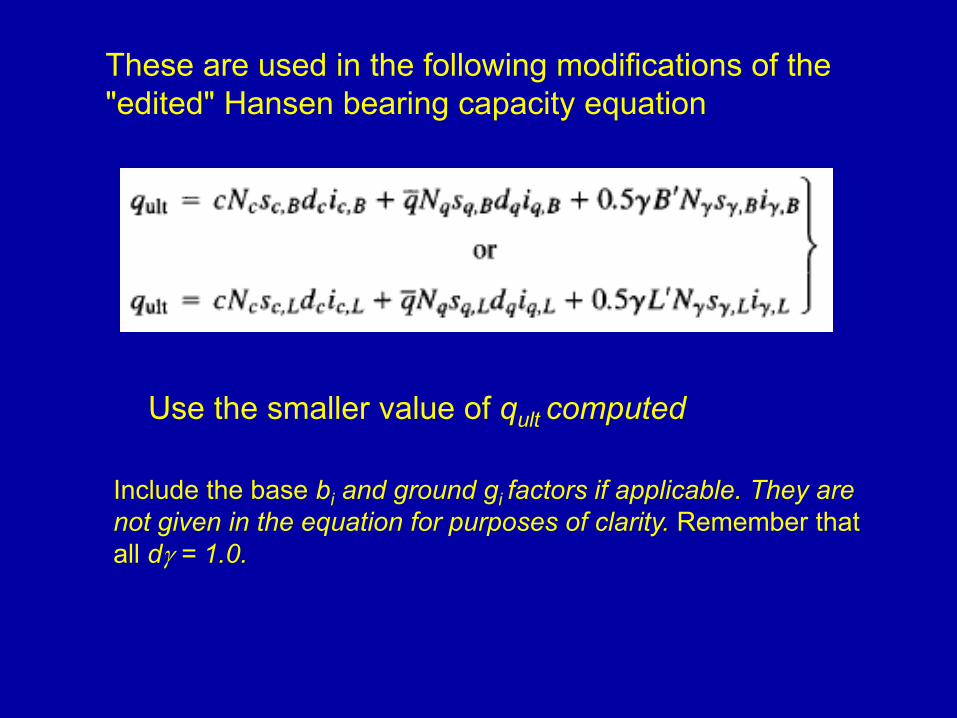
These are used in the following modifications of the "edited" Hansen bearing capacity equation
Use the smaller value of qult computed
Include the base bi and ground gi factors if applicable. They are not given in the equation for purposes of clarity. Remember that all dγ = 1.0.
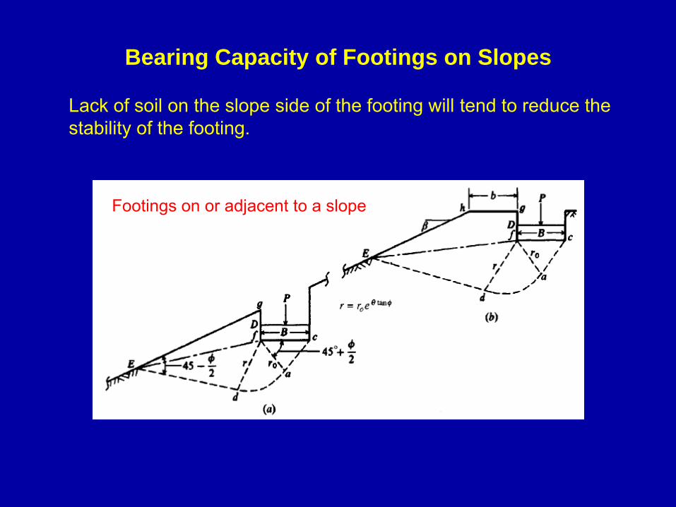
Bearing Capacity of Footings on Slopes
Lack of soil on the slope side of the footing will tend to reduce the stability of the footing.
Footings on or adjacent to a slope
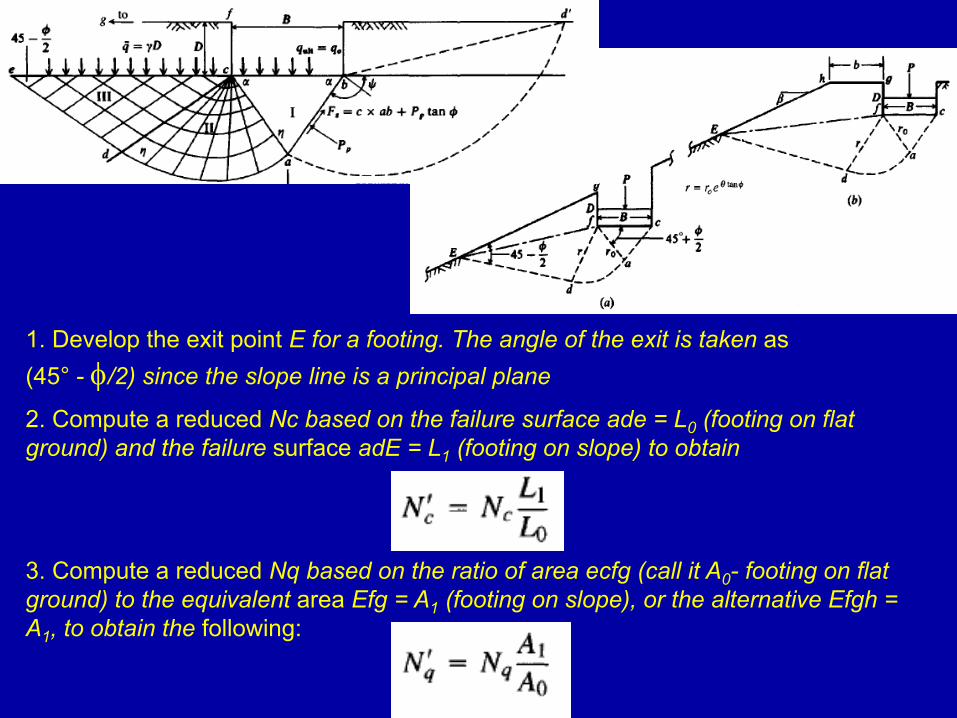
1. Develop the exit point E for a footing. The angle of the exit is taken as (45° - φ/2) since the slope line is a principal plane
2. Compute a reduced Nc based on the failure surface ade = L0 (footing on flat ground) and the failure surface adE = L1 (footing on slope) to obtain
3. Compute a reduced Nq based on the ratio of area ecfg (call it A0- footing on flat ground) to the equivalent area Efg = A1 (footing on slope), or the alternative Efgh = A1, to obtain the following:
Note that when the distance b is such that A1 ≥ A0 we have Nqʹ= Nq. This distance appears to be about b/B > 1.5 (or possibly 2).
4. The overall slope stability should be checked for the effect of the footing load using a slope-stability program. At least a few trial circles should touchpoint c (footing on slope) as well as other trial entrance points on top of and on the slope.
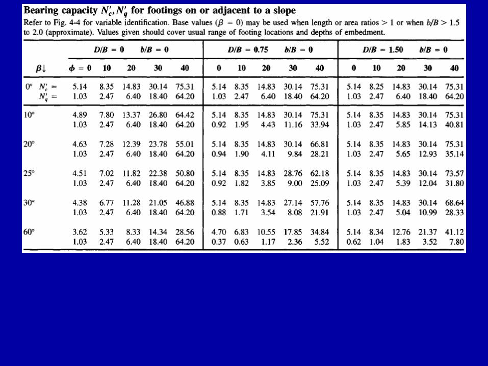
Obtain the Nʹc and Nʹq factors from Table.
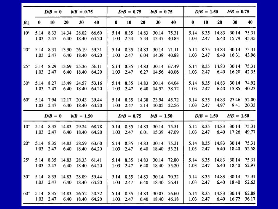
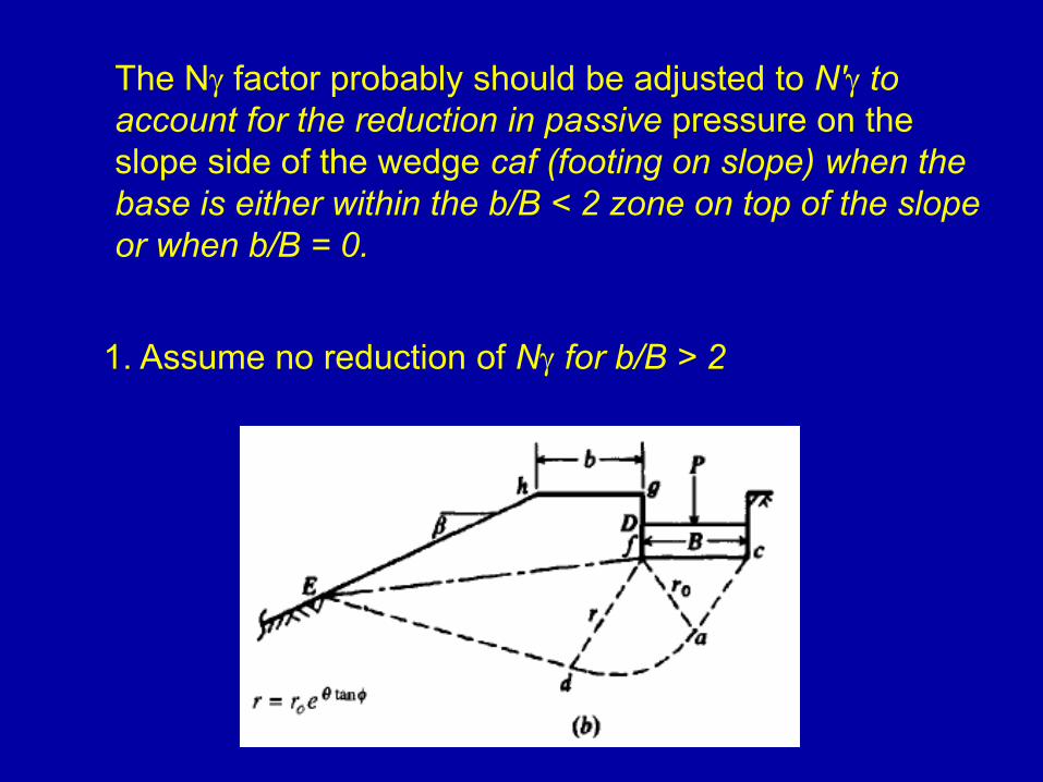
The Nγ factor probably should be adjusted to Nʹγ to account for the reduction in passive pressure on the slope side of the wedge caf (footing on slope) when the base is either within the b/B < 2 zone on top of the slope or when b/B = 0.
1. Assume no reduction of Nγ for b/B > 2
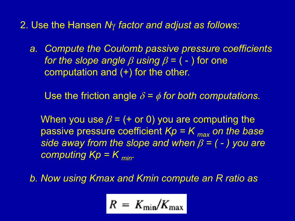
2. Use the Hansen Nγ factor and adjust as follows:
a. Compute the Coulomb passive pressure coefficients for the slope angle β using β = ( - ) for one computation and (+) for the other.
Use the friction angle δ = φ for both computations.
When you use β = (+ or 0) you are computing the passive pressure coefficient Kp = K max on the base side away from the slope and when β = ( - ) you are computing Kp = K min.
b. Now using Kmax and Kmin compute an R ratio as
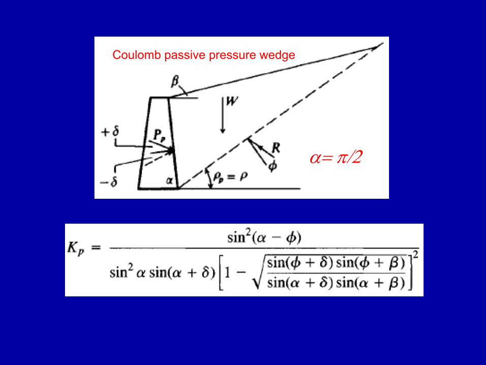
α= π/2
Coulomb passive pressure wedge
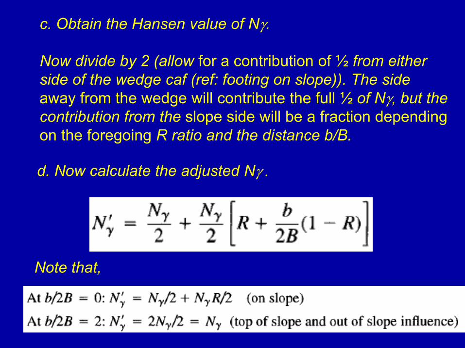
c. Obtain the Hansen value of Nγ.
Now divide by 2 (allow for a contribution of ½ from either side of the wedge caf (ref: footing on slope)). The sideaway from the wedge will contribute the full ½ of Nγ, but the contribution from the slope side will be a fraction depending on the foregoing R ratio and the distance b/B.
d. Now calculate the adjusted Nγ .
Note that,
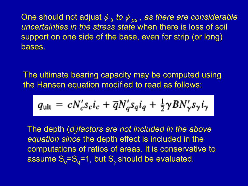
One should not adjust φ tr to φ ps , as there are considerable uncertainties in the stress state when there is loss of soil support on one side of the base, even for strip (or long) bases.
The ultimate bearing capacity may be computed using the Hansen equation modified to read as follows:
The depth (di)factors are not included in the above equation since the depth effect is included in the computations of ratios of areas. It is conservative to assume Sc=Sq=1, but Sγ should be evaluated.

END of Part 1