facade systems - bgc fibre cement nz... · page 05 duragridtm june - 2013 applications advantages...
TRANSCRIPT
AUSTRALIAN OWNED & MANUFACTURED WWW.BGC.COM.AU/FIBRECEMENTWWW.BGCINNOVADESIGN.CO.NZ
DURAGRIDTM
FACADE SYSTEMS
JUNE 2013

INNOVA™
JUNE 2013
INNOVA™ IS A RANGE OF INTERIOR LINING, EXTERIOR FACADE AND FLOORING PRODUCTS WHICH GIVE A NEW DIMENSION TO THE BGC PRODUCT RANGE. THE PRODUCTS WITHIN THE INNOVA™ RANGE HAVE BEEN DESIGNED TO INSPIRE YOU TO CREATE INNOVATIVE AND DYNAMIC DESIGNS WITHIN YOUR BUILDING OR RENOVATION PROJECT.

THE DURAGRID™ FACADE SYSTEM UTILISES BGC FIBRE CEMENT SHEETING, OFFERING THE IDEAL SOLUTION FOR CLADDING THE EXTERIOR OF HOMES AND LOW TO MEDIUM RISE COMMERCIAL CONSTRUCTION.DURAGRID™ GIVES BUILDINGS A MODERN AND EXTREMELY DURABLE FINISH.
DURAGRIDTM SHEET HAS A SMOOTH, FLAT SURFACE AND SQUARE EDGE FINISH WHICH IS SUITABLE FOR EXPRESSED JOINTING AND PROVIDES A FACADE SUITABLE FOR A VARIETY OF PAINT FINISHES.
THE DURAGRIDTM FACADE SYSTEM: / IS LIGHTWEIGHT/ IS HIGHLY DURABLE/ PANELS WILL NOT ROT, BURN OR CORRODE/ PANELS ARE NOT EFFECTED BY INSECTS, AIR, STEAM, SALT OR SUNLIGHT/ CAN BE USED IN WIND ZONES UP TO AND INCLUDING EXTRA HIGH (NZS3604:2011)/ PROVIDES A DEFINITIVE NEGATIVE DETAIL AS ONLY MINIMAL SEALANT IS REQUIRED IN THE VERTICAL JOINT/ QUICK AND SIMPLE TO INSTALL USING MANUAL NAILING, GUN NAILING OR SCREW FIXING/ BRANZ APPRAISED
PAGE 03DURAGRIDTM
JUNE - 2013

CONTENTS
PAGE 04DURAGRIDTM JUNE - 2013
APPLICATIONS / 5ADVANTAGES / 5PRODUCT INFORMATION / 5SHEET TOLERANCES / 5PANEL SIZES AND MASS / 5CONTROL OF EXTERNAL FIRE SPREAD / 5PREVENTION OF FIRE OCCURRING / 5DURABILITY / 5THERMAL CONDUCTIVITY / 5WEATHER RESISTANCE / FREEZE THAW / 5STRUCTURAL BRACING / 5FIRE RATING / 5 HANDLING AND STORAGE / 6ACCESSORIES AVAILABLE FROM BGC / 6FASTENERS / 6-7DESIGN CONSIDERATIONS / 7GROUND CLEARANCE / 7PANEL PREPARATION / 8BACKING STRIP INSTALLATION & SEALING / 8TIMBER FRAMING / 9 CAVITY BATTEN / 9 FIXING DURAGRID™ TO BATTENS / 9DURABATTEN INSTALLATION TO TIMBER / 10BATTEN JOINING / 10INSTALLATION DETAILS / 10-14VERTICAL EXPRESS JOINTS / 15PENETRATIONS, WINDOW & DOOR OPENINGS / 15-16MOISTURE MANAGEMENT / 17FINISHING / 17MAINTENANCE / 17WARRANTY / 18DISCLAIMER / 18

PAGE 05DURAGRIDTM
JUNE - 2013
APPLICATIONS
ADVANTAGES
PRODUCT INFORMATION
Duragrid™ Facade System utilises BGC Fibre Cement panels and graded, timber battens to form a strong and durable facade cladding system.
Duragrid™ is ideally suited for versatile architectural applications in residential and low rise commercial construction. Duragrid™ panels can be fixed over timber framing or lightweight steel framed walls.
Duragrid™ panels are designed for installation in a variety of patterns, including vertical, horizontal or brick-bond.
Duragrid™ panels are available in 9mm thickness and may be finished with site applied acrylic paint systems or a pre-applied high quality polyurethane finish. Exposed head fasteners will need to be used with pre-finished panels. Please contact BGC Fibre Cement (NZ) for advice.
NOTE: The fitting of the Duragrid™ Facade System should only be attempted by a Licensed Building Practitioner (LBP) or specialist installer. BGC can supply a list of recommended installers.
/ Lightweight cladding system/ Readily accepts many forms of decorative finish/ Highly durable/ Dynamic architectural style/ Fully sealed and primed panels
Duragrid™ panels are an autoclaved, cellulose fibre reinforced silica/cement panel, specially formulated and prepared to meet the requirements for use in exterior applications. Duragrid™ panels have a smooth flat surface and a neat square edged finish, for enhanced expressed joint facades. Duragrid™ panels have been back sealed and face primed.
BGC Fibre Cement products are manufactured to the Australian / New Zealand Standard AS/NZS 2908.2-2000 Cellulose-Cement Products, Part 2: Flat sheets and Duragrid™ is classified as Type A Category 3.
CONTROL OF EXTERNAL FIRE SPREAD
The Duragrid™ Facade System has a peak heat release rate of less than 100 kW/m2 and a total heat released rate of less than 25 MJ/m2. In accordance with NZBC Acceptable Solution C/AS1 Table 5.1 the system is suitable for use on buildings with a SH Risk Group classification, at any distance to the relevant boundary. Refer to NZBC Acceptable Solutions C/AS2 – C/AS6 Paragraph 5.8.1 for the specific exterior surface finishes require-ments for other building Risk Groups.
PREVENTION OF FIRE OCCURRING
Separation or protection must be provided to the Duragrid™ Facade System from heat sources such as fire places, heating appliances, flues and chimneys. Part 7 of NZBC Acceptable Solutions C/AS1 – C/AS6 and NZBC Verification Method C/VM1 provide methods for separation and protection of combustible materials from heat sources.
DURABILITY
THERMAL CONDUCTIVITY
STRUCTURAL BRACING
FIRE RATING
MASSKG/M2
11.7
WIDTHmm
1190
590
LENGTH mm
1190 2390 2990 x x x
x
THICKNESSmm
9
Duragrid™ panels are available in the following sizes.
PANEL SIZES AND MASS - TABLE 1
Duragrid™ physical properties ensure it’s durability inexposed applications.
/ Duragrid™ panels are immune to permanent water damage in both short and long-term exposure./ Duragrid™ panels will not rot or burn and are unaffected by insects, air, steam, salt and sunlight./ Duragrid™ panels are not adversely affected over a temperature range of 0°C to 95°C.
SHEET TOLERANCES
/ Width +0/-1mm/ Length +0/-2mm/ Thickness +10%/-0%/ Diagonals difference (max) 2mm/ Edge straightness deviation (max) 1mm
Duragrid™ panels have relatively low thermal conductivity: R-value. At Equilibrium Moisture content the approximate R-Value of Duragrid™ is;- 0.55 W/m°C.
Duragrid™ Facade panels are not suitable for structural bracing.Bracing can be achieved with the addition of Durabarrier as a rigid sheathing/air barrier or using Duraliner™ or Plasterboard as interior linings.
A 30/30/30 FRR can be achieved with the use of Durabarrier – see the Durabarrier brochure for details. For other Fire ratings please contact BGC Fibre Cement (NZ).
WEATHER RESISTANCE / FREEZE THAW
The Duragrid™ Facade system has been successfully tested for weather resistance as per NZBC Verification Method E2/VM1.
Duragrid™ should not be used in situations where it will be in direct contact with snow and ice for prolonged periods.
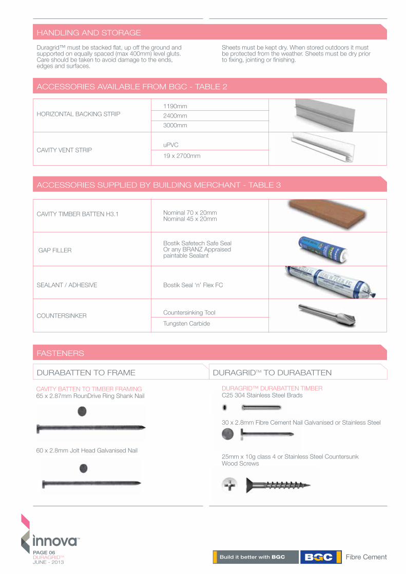
Countersinking ToolTungsten Carbide
COUNTERSINKER
CAVITY BATTEN TO TIMBER FRAMING65 x 2.87mm RounDrive Ring Shank Nail
60 x 2.8mm Jolt Head Galvanised Nail
PAGE 06DURAGRIDTM
JUNE - 2013
HANDLING AND STORAGE
DURABATTEN TO FRAME DURAGRIDTM TO DURABATTEN
ACCESSORIES AVAILABLE FROM BGC - TABLE 2
ACCESSORIES SUPPLIED BY BUILDING MERCHANT - TABLE 3
FASTENERS
Duragrid™ must be stacked flat, up off the ground and supported on equally spaced (max 400mm) level gluts. Care should be taken to avoid damage to the ends, edges and surfaces.
Sheets must be kept dry. When stored outdoors it must be protected from the weather. Sheets must be dry prior to fixing, jointing or finishing.
CAVITY TIMBER BATTEN H3.1 Nominal 70 x 20mm Nominal 45 x 20mm
HORIZONTAL BACKING STRIP
uPVC19 x 2700mm
CAVITY VENT STRIP
GAP FILLERBostik Safetech Safe SealOr any BRANZ Appraised paintable Sealant
1190mm2400mm3000mm
DURAGRID™ DURABATTEN TIMBERC25 304 Stainless Steel Brads
30 x 2.8mm Fibre Cement Nail Galvanised or Stainless Steel
25mm x 10g class 4 or Stainless Steel Countersunk Wood Screws
SEALANT / ADHESIVE Bostik Seal ‘n’ Flex FC
PAGE 07DURAGRIDTM
JUNE - 2013
FASTENERS
GROUND CLEARANCE
DESIGN CONSIDERATIONS
The designer should determine the wind pressure for the project and specify the layout, spacing and fixing to the structure.
The timber structure should be designed to NZS3604. Alternatively the building can be to a specific design using NZS3603 and AS/NZS1170, and the framing must be of at least equivalent stiffness to the framing provisions of NZS3604.
In areas where there is a probability of high wind loading, care should be taken in the design detailing, especially around all openings, corners and other junctions, to ensure the weather resistance of the total system.
Before the Duragrid™ panels and the supporting substructure are installed, particular care should be taken to ensure that all flashing and waterproofing work is complete, including all wall underlay or BGC Durabarrier. If Duragrid™ is installed on an unlined wall i.e. gable end or garage walls then a rigid sheathing/air barrier must be installed i.e. Durabarrier.
For construction within the scope of E2/AS1, it is a requirement to have a horizontal flashing joint at the second storey for construction greater than two stories – see architectural details.
Fixings must comply with the minimum durability requirements of NZBC.
Zone B and C - Hot Dipped or Stainless Steel 316 Zone D - Stainless Steel 316 as per NZS3604:2011
All screw holes must be filled with an epoxy filler such as Megapoxy P1, Hilti CA125 or Hilti CA273 and sanded flush to provide a flat surface for finish coating. When sanding, only sand the screw holes, not the entire sheet surface.
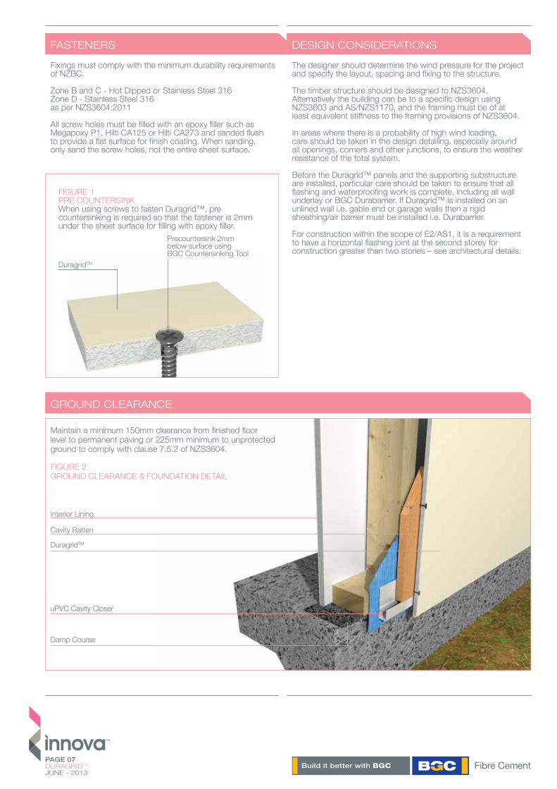
FIGURE 1PRE COUNTERSINKWhen using screws to fasten Duragrid™, pre countersinking is required so that the fastener is 2mm under the sheet surface for filling with epoxy filler.
DuragridTM
Precountersink 2mmbelow surface usingBGC Countersinking Tool
DuragridTM
Damp Course
uPVC Cavity Closer
Cavity Batten
Interior Lining
Maintain a minimum 150mm clearance from finished floor level to permanent paving or 225mm minimum to unprotected ground to comply with clause 7.5.2 of NZS3604.
FIGURE 2GROUND CLEARANCE & FOUNDATION DETAIL
PAGE 08DURAGRIDTM
JUNE - 2013
PANEL PREPARATION
BACKING STRIP INSTALLATION & SEALING
For insitu paint applications, Duragrid™ panels are supplied with a UV cured acrylic primer for durability.
Where it is necessary to cut sheets, cutting tools should have a dust extraction system.
Cut edges must be sealed with BGC Edge Sealer or an acrylic coating to eliminate moisture absorption.
A saw blade such as BGC Durabladewith a poly crystalline diamond tip specifically designed to cut fibre cement sheets is recommended.
Ensure work area is well ventilated and wear an approved dust mask (AS/NZS1715 and AS/NZS1716) and safety glasses (AS/NZS1337).
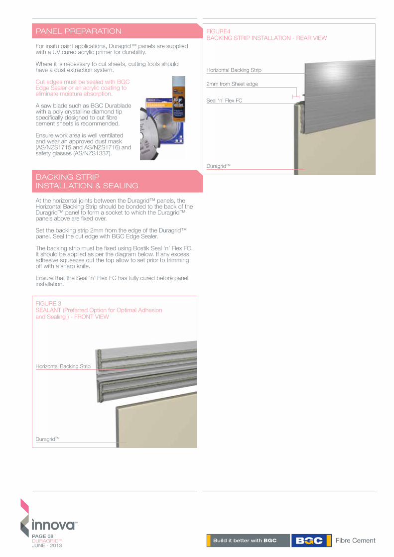
At the horizontal joints between the Duragrid™ panels, the Horizontal Backing Strip should be bonded to the back of the Duragrid™ panel to form a socket to which the Duragrid™ panels above are fixed over.
Set the backing strip 2mm from the edge of the Duragrid™ panel. Seal the cut edge with BGC Edge Sealer.
The backing strip must be fixed using Bostik Seal ‘n’ Flex FC. It should be applied as per the diagram below. If any excess adhesive squeezes out the top allow to set prior to trimming off with a sharp knife.
Ensure that the Seal ‘n’ Flex FC has fully cured before panel installation.
FIGURE 3SEALANT (Preferred Option for Optimal Adhesion and Sealing ) - FRONT VIEW
Horizontal Backing Strip
DuragridTM
FIGURE4BACKING STRIP INSTALLATION - REAR VIEW
Seal ‘n’ Flex FC
Horizontal Backing Strip
2mm from Sheet edge
DuragridTM

PAGE 09DURAGRIDTM
JUNE - 2013
TIMBER FRAMING
CAVITY BATTEN
FIXING DURAGRIDTM TO BATTENS
Ensure that the framing is square and work from a central datum line. The framing must be straight and true to provide a flush face to receive the panels.
BGC Recommend a maximum tolerance of 3-4mm in any 3000mm length of framing. Duragrid™ will not straighten excessively warped or distorted frames and any warping may still be visible after Duragrid™ has been applied.
Timber framing must comply with all current NZ Standards and any specific engineering design specifications.
Timber framing must be treated and have moisture contents as per the requirements of NZS3602.
Duragrid™ requires a minimum framing width of 45mm. Studs spacing must not be greater than 600mm centres. Nog/Dwang spacing must not be greater that 800mm centres.
Timber framing must have a maximum moisture content of 20% at the time of installation of BGC Durabarrier or wall underlay.
The cavity battens on the Duragrid™ vertical sheet joints must be a 70 x 20mm H3.1 cavity batten.
Battens must only be installed on studs.
Structural cavity battens must be fixed with 65 x 2.87mm RounDrive Ring Shank Nails or 60 x 2.8mm Jolt Head Galvanised Nails. They must be fixed at maximum 300mm centres and staggered 12mm either side of the batten centre line.
Intermediate cavity battens can be 50 x 20mm H3.1 cavity battens – there is no requirement to prime or pre coat. They are fixed with 65 x 2.87mm RounDrive Ring Shank Nails or 60 x 2.8mm Jolt Head Galvanised Nails at 300mm centres and staggered 12mm either side of the batten centre line.
Where studs are at greater than 450mm centres and a flexible wall underlay is being used, a building underlay support must be installed over the underlay at maximum 300mm centres horizontally.
The vertical expressed join must coincide with the centre line of the battens. Stud centres may have to be designed to coincide with express joins.
Structural cavity battens must be joined with a 45° weather cut sloping down and away from Durabarrier or wall underlay. Join must be sealed with Bostik Seal ‘n’ Flex FC.
Ensure cavity batten and panel are correctly orientated and sealant has been applied between battens.
Duragrid™ can be fixed with the following fixings in all wind zones including Extra High (NZS3604:2011):
Fixings Fixing Centres From Sheet Edge
Brads Stainless Steel C25 150mm 10mmFibre Cement Nail 30 x 2.8mm 200mm 15mmScrews25mm x 10g 200mm 18mm
All fixing types must be used in conjunction with Bostik Seal ‘n’ Flex FC. Sheets should not be fixed closer than 50mm from the Aluminum back spacer and sheet corners.
Duragrid™ must be fixed to the cavity battens via a continuous 6mm bead of Bostik Seal ‘n’ Flex FC adhesive to all contact surfaces. The intermediate batten must have 2x6mm beads of Seal ‘n’ Flex FC.
Note: Bostik Seal ‘n’ Flex FC must only be applied just prior to the installation of the Duragrid™ sheets as it is a fast cure adhesive.
Duragrid™ sheets and cavity battens must be dry and free of dust, prior to the application of Bostik Seal ‘n’ Flex FC. The adhesive sealant must not be applied at temperatures below 5°.
FIGURE 5FRAME STRAIGHTNESS
PAGE 10DURAGRIDTM
JUNE - 2013
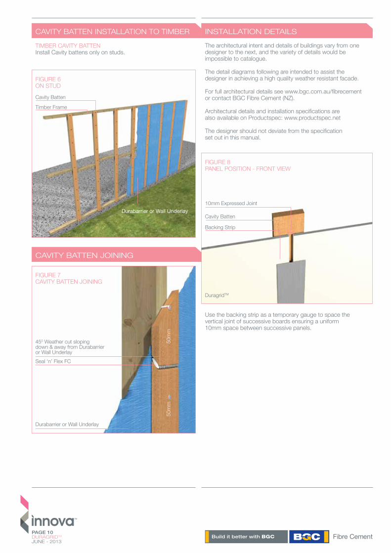
CAVITY BATTEN INSTALLATION TO TIMBER
TIMBER CAVITY BATTENInstall Cavity battens only on studs.
FIGURE 6ON STUD
Cavity Batten
Timber Frame
Durabarrier or Wall Underlay
CAVITY BATTEN JOINING
FIGURE 7CAVITY BATTEN JOINING
450 Weather cut sloping down & away from Durabarrier or Wall Underlay
Durabarrier or Wall Underlay
50m
m50
mm
Seal ‘n’ Flex FC
The architectural intent and details of buildings vary from one designer to the next, and the variety of details would be impossible to catalogue.
The detail diagrams following are intended to assist the designer in achieving a high quality weather resistant facade.
For full architectural details see www.bgc.com.au/fibrecement or contact BGC Fibre Cement (NZ).
Architectural details and installation specifications are also available on Productspec: www.productspec.net
The designer should not deviate from the specification set out in this manual.
INSTALLATION DETAILS
FIGURE 8PANEL POSITION - FRONT VIEW
Cavity Batten
10mm Expressed Joint
DuragridTM
Backing Strip
Use the backing strip as a temporary gauge to space the vertical joint of successive boards ensuring a uniform 10mm space between successive panels.
PAGE 11DURAGRIDTM
JUNE - 2013
INSTALLATION DETAILS
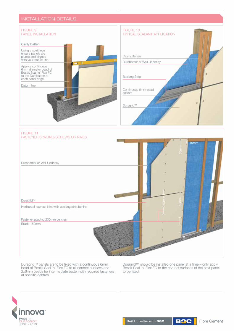
Duragrid™ panels are to be fixed with a continuous 6mm bead of Bostik Seal ‘n’ Flex FC to all contact surfaces and 2x6mm beads for intermediate batten with required fasteners at specific centres.
Duragrid™ should be installed one panel at a time – only apply Bostik Seal ‘n’ Flex FC to the contact surfaces of the next panel to be fixed.
Apply a continuous 6mm diameter bead of Bostik Seal ‘n’ Flex FC to the Durabatten at each panel edge
Datum line
Using a spirit level ensure panels are plumb and aligned with your datum line
Cavity Batten
Cavity Batten
Backing Strip
Continuous 6mm bead sealant
Durabarrier or Wall Underlay
Durabarrier or Wall Underlay
Horizontal express joint with backing strip behind
Fastener spacing 200mm centresBrads 150mm
FIGURE 11FASTENER SPACING-SCREWS OR NAILS
FIGURE 9PANEL INSTALLATION
FIGURE 10TYPICAL SEALANT APPLICATION
DuragridTM
DuragridTM
15mm
50m
m
50m
m50
mm
50m
m
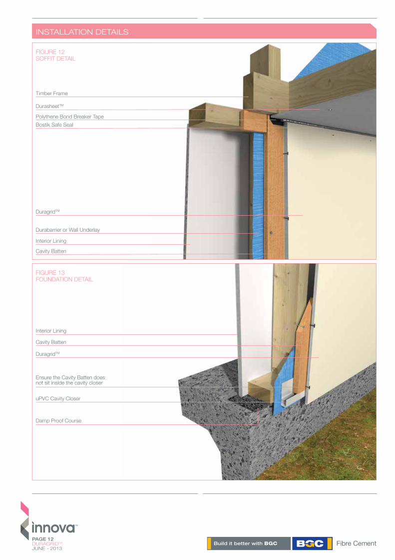
FIGURE 12SOFFIT DETAIL
FIGURE 13FOUNDATION DETAIL
Timber Frame
Interior Lining
Durabarrier or Wall Underlay
DuragridTM
DurasheetTM
Polythene Bond Breaker TapeBostik Safe Seal
Cavity Batten
DuragridTM
Damp Proof Course
uPVC Cavity Closer
Ensure the Cavity Batten does not sit inside the cavity closer
Cavity Batten
Interior Lining
PAGE 12DURAGRIDTM
JUNE - 2013
INSTALLATION DETAILS
PAGE 13DURAGRIDTM
JUNE - 2013
INSTALLATION DETAILS
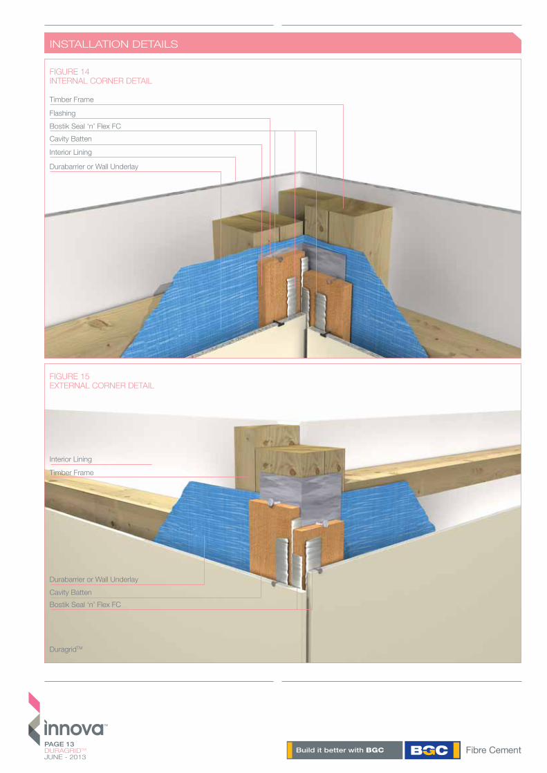
FIGURE 14INTERNAL CORNER DETAIL
FIGURE 15EXTERNAL CORNER DETAIL
Durabarrier or Wall Underlay
Durabarrier or Wall Underlay
DuragridTM
Interior Lining
Interior Lining
Timber Frame
Timber Frame
Flashing
Cavity Batten
Cavity Batten
Bostik Seal ‘n’ Flex FC
Bostik Seal ‘n’ Flex FC
PAGE 14DURAGRIDTM
JUNE - 2013
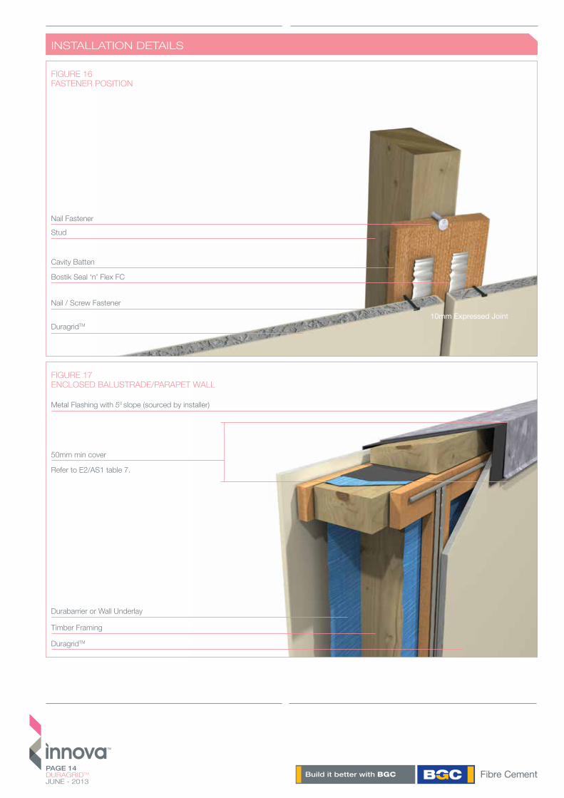
INSTALLATION DETAILS
50mm min cover
Refer to E2/AS1 table 7.
FIGURE 17ENCLOSED BALUSTRADE/PARAPET WALL
Timber Framing
Durabarrier or Wall Underlay
Metal Flashing with 50 slope (sourced by installer)
DuragridTM
DuragridTM
Bostik Seal ‘n’ Flex FC
Nail / Screw Fastener
Cavity Batten
Stud
Nail Fastener
FIGURE 16FASTENER POSITION
10mm Expressed Joint
PAGE 15DURAGRIDTM
JUNE - 2013
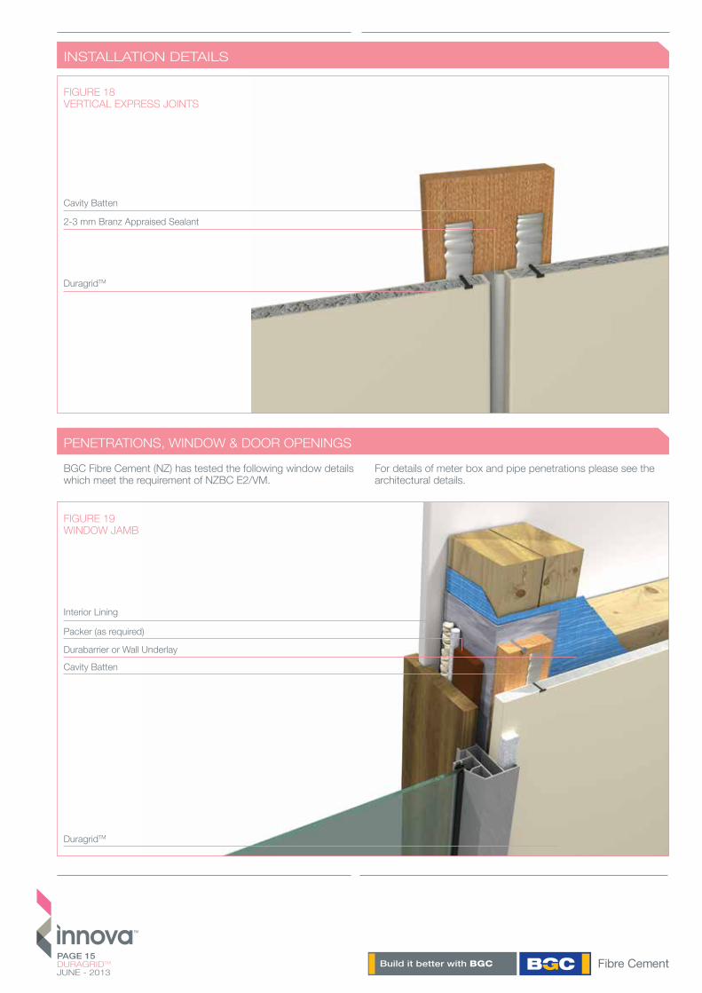
PENETRATIONS, WINDOW & DOOR OPENINGS
INSTALLATION DETAILS
DuragridTM
2-3 mm Branz Appraised Sealant
Cavity Batten
FIGURE 18VERTICAL EXPRESS JOINTS
BGC Fibre Cement (NZ) has tested the following window details which meet the requirement of NZBC E2/VM.
For details of meter box and pipe penetrations please see the architectural details.
FIGURE 19WINDOW JAMB
Interior Lining
Packer (as required)
Durabarrier or Wall Underlay
Cavity Batten
DuragridTM
PAGE 16DURAGRIDTM
JUNE - 2013
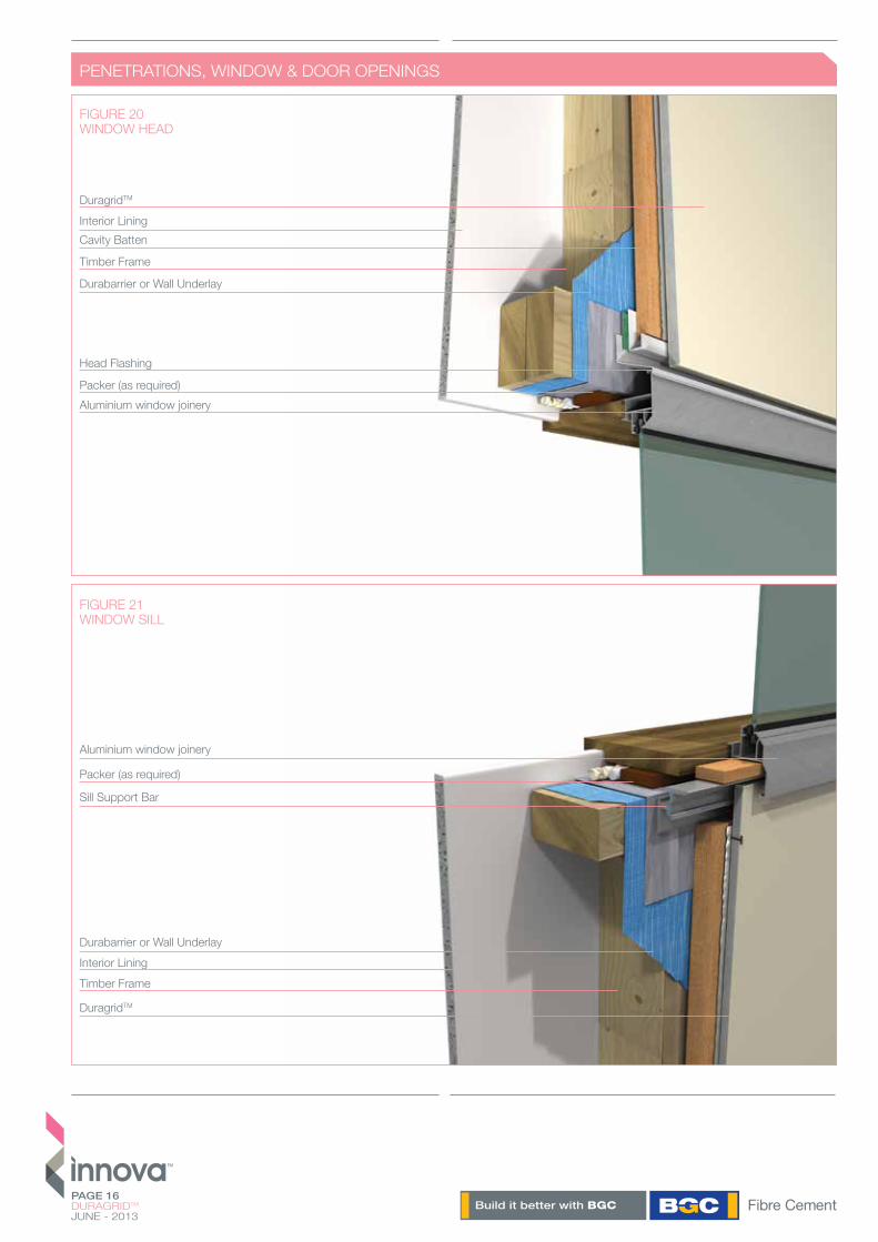
PENETRATIONS, WINDOW & DOOR OPENINGS
FIGURE 21WINDOW SILL
DuragridTM
Aluminium window joinery
Sill Support Bar
Packer (as required)
Interior LiningDurabarrier or Wall Underlay
Timber Frame
FIGURE 20WINDOW HEAD
Aluminium window joinery
DuragridTM
Head Flashing
Packer (as required)
Timber Frame
Cavity BattenInterior Lining
Durabarrier or Wall Underlay

PAGE 17DURAGRIDTM
JUNE - 2013
MOISTURE MANAGEMENT
FINISHING
MAINTENANCE
Designers, specifiers and builders have a duty of care to identify moisture-associated risks with any individual building design.
Wall construction design should consider both the interior and exterior environments of the building to effectively manage moisture. Special consideration should be given to buildings that are in extreme climates or at higher risk of wind driven rain.
In addition, all wall openings, penetrations, junctions, connections, window heads, sills and jambs must incorporate appropriate flashing for waterproofing. All other components, materials and installation methods used to manage moisture in walls should comply with the relevant standards of the New Zealand Building Code.
EPOXY FILLERSAll screw holes must be filled with a 2 part epoxy or fairing cream. Ensure the surface and screw hole is clean and free of moisture prior to applying the epoxy.
Sand flush to the panel surface once cured. Refer to the epoxy manufacturer’s instructions prior to use.
FLEXIBLE SEALANTSIn all vertical Express Joints a 2-3mm gap filler of Bostik Safe Seal Construction Sealant or similar BRANZ Appraised Sealant needs to be applied. This provides a secondary sealant to the system while still providing a definitive negative detail.
Ensure the gap filler is taken to the edge of the Backing Strip at the intersection of the vertical and horizontal joints.
If you intend to paint the detail the same colour as the DuragridTM, apply the Gap filler before painting.
If you intend to have black vertical joints – apply a black BRANZ appraised paintable sealant after the DuragridTM has been painted (mask the edges of DurasheetTM with a suitable masking tape.)
PAINTING Painting of Duragrid™ is required to meet the durability and external moisture management of the NZBC and BGC Warranty.Duragrid™ must be painted within 90 days of installation.
Duragrid™ panels must be clean, dust free and dry before painting. It can be painted any colour. Duragrid™ panels are preprimed with a UV cured priming system and ready for site applied acrylic paint. Duragrid™ panels can be pre coated with various types of finishes but will need to be installed with exposed head fasteners.
For countersunk screw installed panels the sanded epoxy must be spot primed prior to painting.
Building owners are responsible for the maintenance of Duragrid™ facade systems. The maintenance requirements should be determined by the specifier based on the location and exposure of the building.
It is recommended that:/ Regular cleaning at least annually of the paint finish with water and a mild detergent / Do not water blast/ Inspect regularly and repair if required/ Check ground clearances/ Follow paint manufacturer’s recommendations on recoating
For brad installed panels the brad head must be flush with the panel surface and skimmed with a suitable exterior 2 part builders filler. The skimmed area must be spot primed prior to painting. BGC Fibre Cement (NZ) recommend at least 2 coats of high build acrylic paint when brad or nail fixings have been used. For countersunk screw installations, one coat of acrylic primer and two coats of high build acrylic paint to be used. Refer to paint manufacturer’s recommendations for specific details.

PAGE 18DURAGRIDTM
JUNE - 2013
DISCLAIMER
The successful performance of the relevant product depends on a number of factors outside the control of BGC Fibre Cement (NZ). As such, BGC Fibre Cement (NZ) shall not be liable for the recommendations made in its literature and the performance of the products/systems including its suitability for any purpose or ability to comply with the relevant conditions set out in the New Zealand Building Code. It is the responsibility of the building designer to ensure that the details and recommendations pro-vided in the relevant BGC Fibre Cement (NZ) installation guide are suitable for the intended project and that specific design is conducted where appropriate.
The instructions and recommendations in BGC Fibre Cement (NZ) literature are based on good building practice, but are in no way an exhaustive statement of all relevant information and are subject to conditions above. BGC Fibre Cement has tested the performance of its products when installed in accordance with the products technical specification, in accordance with the standards required by the New Zealand Building Code. Those test results demonstrate the products compliance with the performance criteria set out by the New Zealand Building Code.
WARRANTY
BGC Fibre Cement (NZ) warrants its products to be free from defects caused by defective materials or workmanship (manufac-turer) for a period of 15 years from the date of purchase, subject to the conditions set out below. Further, BGC Fibre Cement (NZ) warrants its products to be resistant from rotting, fire and crack-ing so long as the installation is carried out in accordance with BGC Fibre Cement literature available at the time of purchase.
i) This warranty is non transferable.ii) The product must be installed and maintained in accordance with the relevant BGC Fibre Cement (NZ) literature current and available at the time of purchase. All additional products including accessories, jointing systems and coatings used in conjunction with the BGC Fibre Cement product(s) must be applied or installed according to the appropriate manufacturer’s instructions. iii) BGC Fibre Cement (NZ) is not liable for any breach of warranty unless the claimant provides proof of purchase and a claim is submitted in writing within 30 days of the defect becoming evident. If the defect is detected prior to installation, the claim must be submitted before installation occurs.iv) If BGC Fibre Cement (NZ) products are found to be defective, BGC Fibre Cement will at its option, repair or replace the product, supply equivalent replacement products or reimburse the purchase price of the product. v) BGC Fibre Cement (NZ) shall not be liable for any damage or losses (direct or indirect) including property damage or personal injury, economic loss or loss of profits, consequential loss arising in contract or negligence or howsoever arising. BGC Fibre Cement (NZ) shall not be liable for any claims, damages or defects arising from or attributed to poor workmanship, poor design or detailing, settlement or structural movement or movement of materials to which the product is attached, incorrect design of the structure, acts of God, including but not limited to floods, cyclones, earthquakes or severe weather or unusual climate conditions, performance of coatings or paints applied to the product, normal wear and tear, growth of mould, mildew, fungi, bacteria or any other organism on the products surface (exposed or unexposed).vi)The project must be designed and constructed in accordance with all relevant requirements of the current New Zealand Building Code regulations and standards.vii)If satisfying a claim under this warranty which involves recoat-ing or painting of BGC Fibre Cement (NZ) products, there may be slight colour differences between the replacement product and the original products due to the effect weathering and variations in materials over time.viii) All warranties, conditions, liabilities and obligations other than those specified in this warranty are excluded to the fullest extend allowed by the law.

PAGE 19DURAGRIDTM
JUNE - 2013
NOTES
CONTACT
WWW.BGC.COM.AU/FIBRECEMENTWWW.BGCINNOVADESIGN.CO.NZ
DESIGN WWW.THESHAPEGROUP.COM.AU
BGC FIBRE CEMENTPO BOX 76695MANUKAU CITY 2241
TELEPHONE / 09 264 1457FREE PHONE / 0800 424234FACSIMILE / 09 264 1459
WWW.BGC.COM.AU/FIBRECEMENTWWW.BGCINNOVADESIGN.CO.NZ
BGC HAS STATE OF THE ART MANUFACTURING FACILITIES IN PERTH, WA AND DISTRIBUTION CENTRES IN ALL STATES OF AUSTRALIA AND IN NEW ZEALAND.
BGC HAS A TEAM OF TECHNICAL SPECIALISTS WHO CAN ASSIST WITH ALL SPECIFICATION AND DESIGN INFORMATION. BGC PROVIDES BUILDERS, DEVELOPERS AND ARCHITECTS WITH A RANGE OF DESIGN ALTERNATIVES AND INNOVATIVE PRODUCTS SUCH AS:
DURASHEETTM / Fibre cement sheet for exterior applications.
DURATEXTM / Fibre cement sheets for applied finish systems.
DURABACKERTM / Fibre cement sheet for high build plaster coatings.
DURABARRIER / A rigid sheathing/air barrier for all types of timber framed construction.
DURAPLANKTM / Woodgrain and smooth fibre cement plank for exterior applications.
DURAGRIDTM / A lightweight facade giving a modern and durable finish.
DURAGROOVETM / A vertically grooved cladding.
DURASCAPETM / A base sheet with a 5mm shiplap join.
DURALINERTM / Interior lining suitable as a substrate for tiles and is ideal for wet areas.
NULINETM PLUS / Weatherboard cladding system.
STONESHEETTM / Fibre cement stone slip substrate.
SAFE WORKING PRACTICES - PLEASE WEAR A P1 OR P2 MASK AND SAFETY GOGGLES (APPROVED TO AS/NZW1337 STANDARDS) WHILST CUTTING OR INSTALLING DURAGRIDTM. DURAGRIDTM CAN BE SAFELY HANDLED DURING UNLOADING OR STACKING WITHOUT THE USE OF THESE PRECAUTIONS.
CLEANING UP - ALWAYS WET DOWN YOUR WORK AREA WHEN CUTTING DURAGRIDTM, TO ENSURE THAT DUST IS MANAGED. DISPOSE OF ANY VACUUMED DUST WITH CARE AND USING CONTAINMENT PROCEDURES.