exper mental techn materi - inflibnetshodhganga.inflibnet.ac.in/bitstream/10603/6248/6/06_chapter...
TRANSCRIPT

ClUyapUJ: 2
EXPER MENTAL TECHNMATERI
The specifications of the materials and details of the experimental
techniques used in this study are given in this chapter.
2.1 Materials
2.1.1 Rubbers: Natural rubber
The natural rubber used in this study was ISNR-5 of Mooney
viscosity (ML 1+4,100°C) 85, obtained from the Rubber Research Institute
of India, Kottayam. The Bureau of Indian Standards specifications for the
grade of rubber are given in Table 2.1.]
Table 2.1. BIS specifications of ISNR· 5
SI. No Parameters Limit
1 Dirt content, % by mass, max 0.05
2 Volatile matter, % by mass, max 0.8
3 Nitrogen, % by mass, max 0.6
4 Ash, % by mass, max 0.6
5 Initial plasticity, Po, Min 30
6 Plasticity retention index (PRI), min 60
Rubber from the same lot has been used for the experiment since it
is known that the molecular weight, molecular weight distribution and
non-rubber constituents of natural rubber are affected by clonal variation,
season, use of yield stimulants and method of preparation.'
47

Natural rubber latex: High ammonia type 60% centrifuged natural rubber
latex conforming to the specifications of the Bureau of Indian Standards
(BIS 5430-1981) was used in the study. The properties of the latex used are
given below.
Table 2.2. Specifications of NR latex
Dry rubber content, % by mass 60.040
Total solids content, % by mass 61.050
Coagulum content, % by mass 0.030
Sludge content, % by mass 0.007
Alkalinity as ammonia, % by mass 0.730
KOHnumber 0.496
Epoxidised natural rubber (ENR) latex
Epoxidised natural rubber, ENR 50 containing 50 mole percent of
oxirane rings, prepared in the pilot plant facility of the Rubber Research
Institute of India is used in the study. 1) Rc - 2..01·
Acrylonitrile butadiene rubber (NBR)
Nitrile Rubber, NBR 553 M of medium acrylonitrile content (33% by
weight) a product of Gujarat Apar Polymers Ltd., India was used for the
study.NBR latex: NBR latex - NLX 523 supplied by Apar industries ltd
Gujarat was used in the study. The specifications of the material are given
in Table 2.3.
Table 2.3. Specifications of NBR latex
Total solids content 48 - 52%
pH 8.5 -10
Brookefield Viscosity 100 eps
Surface tension 36 - 43 at 100°C

Styrene Butadiene Rubber (SBR)
Styrene Butadiene Rubber used was Synaprene 1502 grade,
obtained from Synthesis and Chemicals Ltd., Barely, V.P., India. The
Mooney viscosity (ML 1+4,100°C) was 52. The specifications are given
below:
Table 2.4. Specifications of SBR
Volatile matter, % by mass 0.23
Ash, % by mass 0.24
Organic acid, % 5.53
Soap Traces
Bound styrene, % by mass 24.00
SBR latex: SBR latex Encord 204, supplied by Jubilant Organosys Ltd.
Gujarat, having the following specifications is used for the study
Table 2.5. Specifications of SBR latex
Total solids content (%) 50
pH 11.35
Brookefield viscosity (CPs) 29
Surface tension (dynes / cm) 54.4
Specific gravity 0.96 - 1.00
2.1.2 Fillers: The fillers used are silica and carbon black
Silica: Two grades of silica were used.
Vltrasil VN3: Precipitated nano silica, a product of Degussa AG,
Germany. Specifications of the same are given below}

Table 2.6. Specifications of VN3
Specific surface area (N2), m2/ g 175
Heating loss, % 5.5
pH 6.2
Tapped Density, g/l 220
Si02, content % 98
Appearance white powder
Commercial silica: Precipitated silica of commercial grade supplied by Minar
Chemicals, Kochi. It had the following specifications.
Table 2.7. Specifications of Commercial silica
pH (5% aqueous solution) 6.3
Density (g/ cc) 2.03
Si02 content (%) 90
Loss of heating (%) 2.5 %
Carbon black
High Abrasion Furnace Black (N330), a product of M/ s. Philips
Carbon Chemicals Ltd, Kochi was used. It had the following specifications
Table 2.B. Specifications of carbon black
Appearance Black granules
DBP absorption (cc/100g) 102
Pour Density (Kg/m3) 376
Iodine adsorption number 82
Loss on heating (%) 2.5

'E:{perimenta( 'Tecliniques amf :Materiafs used
2.1.3 Coupling Agent
The coupling agent used was Si 69, a product of Degussa AG,
Germany. Chemically the product is bis (triethoxysilyI propyl)
tetrasulphide. The specifications of the product are given below.4
Table 2.9. Specification.s of Si 69
Sulphur content, % 22.7
Vola tiles, % <4.0
Average molecular weight, g/ mol 532
Density, g/ cm3 2.5
Appearance clear yellow liquid
2.1.4 Other chemicals
Toluene and MEK used in the present investigation were of
analytical grade. Sodium silicate, Ammonium chloride and acetic acid
used were of commercial grade. Zinc oxide (activator), Stearic acid (co
activator), N-Cyclohexyl benzthiazyl sulphenamide (accelerator), Tetra
Methyl Thiuram disulphide (accelerator), Diethylene glycol (activator)
Sulphur (crosslinking agent), Naphthenic oil and Aromatic oil (process
oils) used were of commercial rubber grade.
2.2 Experimental methods
2.2.1 Characterisation techniques Mooney viscosity
Mooney viscosity of silica masterbatches was determined using a
Shimadzu Mooney Viscometer, model SMV 202.
ICP- AES analysis
The purity of the ignited silica was tested with Inductively Coupled
Plasma Atomic Emission Spectroscopy. The analysis was conducted with an
ICP AES of Thermo Electron Corporation model IRIS INTREPID 11 XSP.

Cliapter-2
Infrared Spectroscopy
The IR spectra of the coagulum with and without silica were recorded
with Fourier Transform Infrared Spectroscope, Bruker, Tensor 27 model.
2.2.2 Thermal analysis
Thermo Gravimetric Analysis
The thermograms of natural rubber, silica master batches and
composites are recorded with a Thermo Gravimetric Analyzer Q-SO, TA
instruments. It is computer-controlled instrument that permits the
measurement of the weight changes in the sample material as a function
of temperature. The sample placed in a temperature programmed
furnace is subjected to temperatures in the ranges 30'C to 80QGC with a
heating rate of 10°C/ minute and the corresponding weight changes were
noted with the help of a ultra sensitive microbalance. Air and nitrogen
were used as purge gases
Differential Scanning Colorimetric analysis
The Differential Scanning Colorimetry of natural rubber before and
after the silica incorporation is recorded with a Differential Scanning
Colorimeter Q - 100, TA instruments. The energy changes associated with
transitions were recorded in a temperature range of -60 to 100 0 C. Samples
of known weight encapsulated in standard aluminium pans placed in the
sample holder were subjected to the analysis.
2.2.3 USAXS Analysis
The ignited silica and the coagulum containing silica were
studied with Ultra Small Angle X-ray Scattering (USAXS) analysis ..
USAXS helps to study the structure of mass fractal aggregates over
several orders of magnitude of. the length scale.s The scattering
intensity I (cm·1) is plotted as a function of corresponding scattering

'EXperimenta{ tfecliniques aruf <MaterWfs used
vector q (A-t). The USAXS data were obtained from the UNICAT 33-
ID beam line at the Advanced Photon Source, Argonne National
Laboratory, US.
2.2.4 Bound rubber content
The fraction of the bound rubber that occurred in the master batches was
detennined by the following procedure.6 Specimen of 1rnm thickness and 1cm
diameter was cut from the master batches and put into a previously weighed
cage made by stainless steel wire gauze of 280 mesh. The cage was soaked in
the solvent for 72 hours. The cage was taken out after 72h and air-dried. The
bound rubber content Rll was calculated using the equation ';
RB= Wlg-W [m! / (mr + mp)] / W [mp /( mf + mp)] * 100...... 2.1
Where Wfg "" weight of filler and gel, W = weight of specimen,
fif = weight of filler in the compound, mp = weight of polymer.
2.2.5 Vulcanisation
Mixing and homogenisation of the rubber compound
The compounding was done on a laboratory size two roll-mixing
mill (16x33cm) at a friction ratio of 1:1.25 for natural rubber 1:1.1 for
styrene butadiene rubber and nitrile rubber as per ASTM D 3182-89. A nip
gap of 0.2mrn was set and the temperature maintained at 70±5°C. For
mastication of rubber, the elastomer was passed through the rolls. After
the nerve had disappeared, the compounding ingredients were added as
per procedure given in ASTM 0 3184-89 (2001). After the complete
mixing, the stock was sheeted out at a nip gap of 3mm. Mixing time and
temperature were controlled during the process.
Cure characteristics
Cure characteristics of the mixes were detennined as per ASTM D
2084-1QQI'l l1<:ino- R11hhPT PTf)CP<:<: An~lv<:PT (RPA ,)OOO-Alnha Technolo~es). It
Cftapter-2
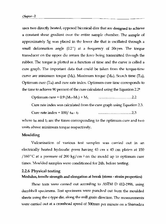
uses two directly heated, opposed biconical dies that are designed to achieve
a constant shear gradient over the entire sample chamber. The sample of
approximately 5g was placed in the lower die that is oscillated through a
small deformation angle (0.2°) at a frequency of 50cpm. The torque
transducer on the upper die senses the force being transmitted through the
rubber. The torque is plotted as a function of time and the curve is called a
cure graph. The important data that could be taken from the torque-time
curve are minimum torque (ML), Maximum torque (MH), Scorch time (TlO),
Optimum cure (T90) and cure rate index. Optimum cure time corresponds to
the time to achieve 90 percent of the cure calculated using the Equation 2.28
Optimum cure = 0.9 (MwML) + ML ........................... 2.2
Cure rate index was calculated from the cure graph using Equation 2.3.
Cure rate index = 100/ t90- t2 ........................... 2.3
where t90 and 12 are the times corresponding to the optimum cure and two
units above minimum torque respectively.
Moulding
Vulcanisation of various test samples was carried out in an
electrically heated hydraulic press having 45 cm x 45 cm platen at 150
/160°C at a pressure of 200 kg/cm 2 on the mould up to optimum cure
times. Moulded samples were conditioned for 24h. before testing.
2.2.6 Physical testing
Modulus, tensile strength and elongation at break (stress - strain properties)
These tests were carried out according to ASTM 0 412-1998, using
dumbbell specimens. Test specimens were punched out from the moulded
sheets using the c-type die, along the mill grain direction. The measurements
were carried out at a crosshead speed of 500mm per minute on a Shimadzu

Model AGl Universal Testing Machine according to ASTM standards, D 412-
68 and D 624-54 respectively.
Tear resistance
Tear resistance of the samples was tested as per as ASTM D 624-1998,
using Wl.-nicked 90° angle test specimens that were pWl.ched out from the
moulded sheets, along the mill grain direction. The measurements were carried
out at a crosshead speed of 500rnm per minute on a Shimadzu Model AGl
Universal Testing Machine according to ASTM standards, D 412-68 and 0 624-
54 respectively. The tear strength was reported in N / nun.
Hardness
The testing was done as per ASTM D 2240-1997 using Shore A type
Durometer.8 Readings were taken after 15 seconds of the indentation
when firm contact has been established with the specimens.
Rebound resilience
Basore Resilometer as per ASTM D2632-01 is used to measure
rebound resilience. The sample was held in position by suction. It was
conditioned by striking with the indentor six times. The test was carried
out at 28+1 cc. Rebound resilience was calculated using Equation 2.4.
Rebound resilience (%) = (1- cosB2 )' 100 (1- cosBt )
2.4
where 81 and 82 are the initial and rebound angles respectively. In all the
Abrasion resistance
The abrasion resistance of the samples were studied with a DIN Abrader
(DIN 53516). Moulded samples of 6±0.2mm diameter and 12mm thickness
were prepared as per ASTM D 3183 and abrasion loss was measured as per
ASTM D5963-04. Abrasion loss was calculated using the equation

Abrasion loss = (loss of wt./sp.gr.)
Compression set
The samples (1.25 cm thick and 2.8 cm diameter) in duplicate
compressed to a constant deflection (25 %) were kept in an air oven at
70°C for 22h (ASTM D 395-1998 method B)'. The samples were taken out,
cooled to room temperature for half an hour and the final thickness
measured. The compression set was calculated using Equation 2.5.
Compression set (%) = to -I) 100 ........................... 2.5 to -t.
where to and tl are the initial and final thickness of the specimen and ts is
the thickness of the spacer bar used.
Heat build up
The Goodrich flexometer conforming to ASTM D 6~~1999 was used for
measuring heat build-upS. A cylindrical sample of 2.5 cm in height and 1.9 cm
in diameter was used for the test. The oven temperature was maintained at
50°C. The sample preconditioned in the oven for 20 minutes was subjected to a
flexing stroke of 4.45 mm under a load of 10.9 kg. The temperature rise (4T°C)
at the end of 20 minutes was taken as the heat build-up.
Flex cracking
Flex cracking was determined using a De Mattia flexing machine
according to ASTM D 430-1995.8 Standard specimens 15 cm x 2.5 cm x 0.6
cm having a semicircular groove moulded transversely in the centre of the
strip were used. Samples fixed on the machine were subjected to flexing at
a frequency of 300 cycles per minute. The number of cycles required to
produce different levels of cracking was noted.

Rheological properties
The flow properties of the rubber-filler mixes were studied by
conducting frequency sweep studies in an instrument REOLOGICA
instrument AB. Samples for testing were consequently prepared by die
cutting 46mm diameter disks out of around 2mm thick sheets of materials.
The frequencies were varied up to 100Hz and the viscosity was measured
at temperature 100°C.
2.2.7 Thermal ageing studies
Tests were carried out as per ASTM D 573-1999.8 Specimens of
vulcanized rubber were exposed to the deteriorating influence of air at
specified elevated temperature in an air oven, for known periods of time,
after which their physical properties determined. These were compared with
the properties determined on the original specimens and the changes noted.
2.2.8 Transmission Electron Microscopy (TEM)
The TEM imaging was carried out for the silica mixes of NR with
different concentrations of silica using a Transmission Electron
Microscope CM-200 of Philips Technology.
2.2.9 Scanning electron microscopy (SEM)
In SEM, the electron beam incident on the specimen surface causes
various phenomena of which the emission of secondary electrons is used
for the surface analysis. Emitted electron strikes the collector and the
resulting current is amplified and used to modulate the brightness of the
cathode ray tube. There is a one- to- one correspondence between the
number of secondary electrons collected from any particular point on the
specimen surface and the brightness of the analogous point on the screen
and thus an image of the surface is progressively built up on the screen.
Scanning electron microscopic studies of the various silica filled
samples were carried out in order to find out the variations in filler
dispersion. The microscopic examinations were carried out on the freshly
cut surface in a Hitachi SE Microscope (model H 6010). The sample
surface was gold coated prior to the examination.
2.2.10 Strain sweep studies
The strain sweep measurements on unvulcanized samples and
vulcanizates were conducted to study the rubber-filler interaction. Rubber
Process Analyzer (RPA 2000 - Alpha Technologies) is a purposely
modified commercial dynamic rheometer.9 Such instrument was modified
for capturing strain and torque signals, through appropriate software.
Filled rubber materials (vulcanized) exhibit strong non-linear viscoelastic
behaviour, the well-known Payne effect, i.e. the reduction of elastic
modulus with increasing strain amplitude.lo RPA can do strain sweep
tests in which the variation of storage modulus (G'), loss modulus (G")
and complex modulus (G*) with the change in strain amplitude are
measured. With respect to its measuring principle, the RP A cavity must
be loaded with a volume excess of test material. In agreement with ASTM
5289, the manufacturers recommends to load samples of about 5.0g i.e. 4.4
cm 3 for a standard filled rubber compound with a specific gravity of
1.14gjcc. Samples for RPA testing were consequently prepared by die
cutting 46mm diameter disks out of around 2mm thick sheets of materials.
The testing temperature was selected as 100 o e; a temperature below the
curing temperature and the shear strain was varied from 0.5% to 100%
keeping the frequency of measurements at O.5Hz.
For strain sweep measurements of cured compounds, uncured
material is used as the test sample that is cured to its optimum cure time

in the RPA cavity and then the strain sweep tests were carried out at 50°C
in a two-stage programme.
2.2.11 Swelling studies
Contribution to the reinforcement effect arises from molecular
interaction between the rubber and the filler. This interaction leads to an
increase in the effective degree of crosslinking and can be evaluated by
equilibrium swelling. The equilibrium swelling analysis of rubber vulcanizate
is known to indicate the number of effective network chains per unit volume
of rubber. For a filled vu1canizate it should reflect not only the effect of
chemical linkages but also the density of polymer-filler attachments.
Circular specimens of diameter 20 mm. were punched out from the
vulcanized sheets. Thicknesses and diameters of the specimens WE're
measured by means of a screw gauge and vernier calipers respectively.
Specimens of known weight were immersed in the solvents and automobile
fuels and oils in diffusion test bottles and kept at room temperature.
Samples were removed from the bottles at periodic intervals and the wet
surfaces were quickly dried using tissue paper and the weights of the
specimen after swelling were determined at regular intervals until no
further increase in solvent uptake was detected.
Degree of swelling usually is expressed as Vr and is defined as Vr =
Volume of rubber / Volume of swollen rubber-solvent gel. Vr is dependent
on the swelling power of the solvent (high swelling power ~eans low Vr ) and
the crosslink deu'iity. Higher crosslink density results in restraint on the
network, which results in lower swelling. Vr of the unfilled vu1canizate is
usually denoted as Vo and that of the filled vulcanizate as V .. f.
Vd = Volume of rubber (filled) / Volume of swollen rubber-solvent gel
(filled) where the numerator refers to total volume minus the filler volume

and the denominator refers to the total swollen volume minus the filler
volume. Volume fraction measurements could also be used for calculating
the crosslink density using Flory- Rehner equation.ll
. . [1 n (1- V) + V + 'YV 2] Crosslmk denSIty = r .~_I\._r_
2p Vs (V,) 113
Where Vs = molar volume of the solvent
x = rubber - solvent interaction parameter
2.2.12 Air permeability
The air permeability of the samples were tested by conducting the
Manometric gas Permeability Testing in a Lyssy Manometric Gas
Permeability Tester, L 100-2402. Vulcanised sheets of::;, 2mm were used for
the study.
2.3 References
1 p.s.s. Babu, K.S. Gopalakrishnan and J. Jacob, In: 'Natural Rubber: Agromanagement and Crop Processing'. Eds. P.J. George, c.K. Jacob, Rubber Research Institute of India, Kottayam, 2000, Ch. 24, 434.
2 A. Subramanyam, Proc. of RR.LM. Planter's Conference, 1971, Kuala Lumpur, 255.
3 Degussa, Product information sheet on 'Ultrasil VN3', PI 203. lE - from the website www.degussa-fp.com.
4 Degussa, Product information sheet on 'Si 69', PI. 320, from the website www.degussa-fp.com.
5 F.G. Teng. Y.M. Jiang. Structure Analyzing of X-ray and characterisation of Material's properties. Science Press, Beiging, 1997.
6 Kazumasa Yoshikai, Tetsuro Oshakai, Mutsuhisa Furukawa, J. Appl. Polym. Science, 2002, 85,2053.
7 S. Wolff, M.J. Wang, E.H. Tan, Rubber Chem. Technol., 1993, 66,163.
8 ArUlual Book of ASTM Standards, 2000.
9 Jean L. Leblanc and Marie Cartault, J. Appl. Polym. Sci., 2001,80 (11), 2093-2104.
10 A.R. Payne, W.E. Whittaker, Rubber Chem. Technol., 1971, 44, 440.
11 P.]. Flory and]. Rehner, J. Chem. Phys., 1943, 11,512.