exit device - bsi-hardware.com · dogging kit: panic device - hex key dogging (rd) standard ......
TRANSCRIPT

Innovation, Quality, Expertise, Efficiency Building Solution International
www.bsi-hardware.com
EXIT DEVICEEXIT DEVICE5810 SERIES GRADE 1 PUSH BAR
SPECIFICATIONS
APPLICATION
HEAD COVER OPTIONS
STRIKES
Certification
Device Lengths: Short (36”): 33-15/32” (850mm), Long (48”): 44-3/4” (1137mm) Door Widths: 36” - For 29” to 36” (736mm to 914mm) door size 48” - For 33” to 48” (838mm to 1219mm) door size Minimum Stile Width: 4-1/4” (107mm) Latch Bolt: 3/4” (19mm) throw, deadlocking design Strikes: 801 (panic), 802 (fire) Dogging Kit: Panic device - Hex key dogging (RD) standard Fire device - No mechanical dogging (ND) Dogging Options: Cylinder Dogging (CD), Less Dogging (LD) Mounting Fasteners: Panic device - Machine screws furnished standard Fire device - Sex nuts and bolts (SNB) supplied standard SNB are required to use for wood doors, order SNB separately Mounting Height: Device centerline from finished floor is 40” (1016mm) standard Projection: Push bar Neutral: 3-1/16” (78mm), Push bar Depressed: 2-19/32” (66mm)
5810S rim exit devices are used for all types of single and double doors with mullion. 5810F rim exit devices are used for UL listed fire labeled single doors up to 4’ x 8’ (1219mm x 2438mm) or 8’ x 8’ (2438mm x 2438mm) double doors with mullion. The exit devices are available in the following finishes: US3, US4, US10, US10B, US26, US26D and US32D.
UL/cUL Listed: UL listed as Panic Exit Hardware or 3-hour Fire Exit Hardware ANSI Certified: Devices are ANSI A156.3 - 2001 Grade 1
5810S Panic-Rated Rim Exit Device5810F Fire-Rated Rim Exit Device
ANSI Accredited ProgramPRODUCT CERTIFICATION
5810F Fire Rated Rim Exit Device
HEAD COVER OPTIONS
HC-1 HC-2
801(panic)
3-5/16”(85mm)
1-7/32”(31mm)
802(Fire)
3-5/16”(85mm)
1-7/32”(31mm)

Innovation, Quality, Expertise, Efficiency Building Solution International
www.bsi-hardware.com
5820 SERIES GRADE 1 PUSH BAR
SPECIFICATIONS
APPLICATION
HEAD COVER OPTIONS
STRIKES
Device Lengths: Short (36”): 33-15/32” (850mm), Long (48”): 44-3/4” (1137mm) Door Widths: 36” - For 29” to 36” (736mm to 914mm) door size 48” - For 33” to 48” (838mm to 1219mm) door size Minimum Stile Width: 4-1/4” (107mm) Latch Bolt: Stainless steel two-pieces mechanical 3/4“ (19mm) with anti-friction insert and auxiliary deadlocking latch Strikes: Universal curved lip, non-handed, 818(panic), 828(fire). Optional 831(panic) or 832 (fire) flat ANSI Strike for door pairs with overlapping astragal (7/8” lip) Dogging Kit: Panic device - Hex key dogging (RD) standard Fire device - No mechanical dogging (ND) Dogging Options: Cylinder Dogging (CD), Less Dogging (LD) Mounting Fasteners: Panic device - Machine screws furnished standard Fire device - Sex nuts and bolts (SNB) supplied standard SNB are required to use for wood doors, order SNB separately Mounting Height: Device centerline from finished floor is 40” (1016mm) standard Projection: Push bar Neutral: 3-1/16” (78mm) Push bar Depressed: 2-19/32” (66mm)
5820S motrise lock exit devices are used for all types of single and double doors. 5820F mortise lock exit devices are used for UL listed fire labeled single doors up to 4’ x 8’ (1219mm x 2438mm) or (2438mm x 2438mm) double doors installations. The exit devices are available in the following finishes: US3, US4, US10, US10B, US26, US26D and US32D.
5820S Panic-Rated Mortise Lock Exit Device5820F Fire-Rated Mortise Lock Exit Device
ANSI Accredited ProgramPRODUCT CERTIFICATION
HC-1 HC-2
5830 SERIES GRADE 1 PUSH BAR
SPECIFICATIONS
APPLICATION
HEAD COVER OPTIONS
STRIKES
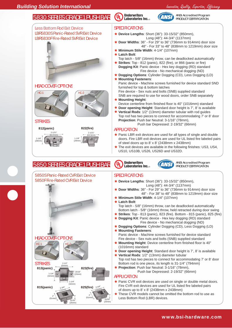
Device Lengths: Short (36”): 33-15/32” (850mm), Long (48”): 44-3/4” (1137mm) Door Widths: 36” - For 29” to 36” (736mm to 914mm) door size 48” - For 38” to 48” (838mm to 1219mm) door size Minimum Stile Width: 4-1/4” (107mm) Latch Bolt: Top latch - 5/8” (16mm) throw, can be deadlocked automatically Bottom latch - 5/8“ (16mm) throw, held retracted during door swing Strikes: Top - 812 (panic), 822 (fire). Bottom - 815 (panic), 825 (fire) Dogging Kit: Panic device - Hex key dogging (RD) standard Fire device - No mechanical dogging (ND) Dogging Options: Cylinder Dogging (CD), Less Dogging (LD) Mounting Fasteners: Panic device - Machine screws furnished for device standard SND furnished for top & bottom latches Fire device - Sex nuts and bolts (SNB) supplied standard SNB are required to use for wood doors, order SNB separately Mounting Height: Device centerline from finished floor is 40” (1016mm) standard Door opening Height: Standard door height is 7’, 8’ is available Vertical Rods: 1/2“ (13mm) diameter tubular with rod guides Top rod has two pieces to connect for accommodating 7’ or 8’ door Bottom rod is one piece, its length is 31-1/4” (794mm) Projection: Push bar Neutral: 3-1/16” (78mm) Push bar Depressed: 2-19/32” (66mm)
Panic SVR exit devices are used for all types of single and double doors. Fire SVR exit devices are used for UL listed fire labeled pairs of doors up to 8’ x 8’ (2438mm x 2438mm)
ANSI Accredited ProgramPRODUCT CERTIFICATION
HC-1 HC-2
4-13/16”(123mm)
1-7/32”(31mm)
3-5/16”(85mm)
1-7/32”(31mm)
818(panic) 828(fire)
HEADAD CCOVER OPTIONS
M a S O
58 0 e a ed o se oc e ce
For use on 1-3/4”standard or 2-1/4” thick single door,and 2-1/4” doubledoor with overlapping astragal and coordinator
5830S Panic-Rated SVR Exit Device5830F Fire-Rated SVR Exit Device5830F-1 Fire Rated SVR Exit Device
COVVVEERER OPTIO
F-1 Fire Rated SVR
HC 2
R Exit Device
ONSSS
d SVR
2-1/21”(63.5mm)
1-1/8” (29mm)
822(fire) 1-1/8”(29mm)
2-1/21”(63.5mm)812(panic)
2”(51mm)
31/32”(25mm)
2-3/4”
(70mm)815(panic) 2-3/4”
(70mm)
2”(51mm)
31/32”(25mm)
825(fire)
Innovation, Quality, Expertise, Efficiency Building Solution International
www.bsi-hardware.com
2”(51mm)
31/32”(25mm)
2-3/4”
(70mm)815(panic)
813(panic) 823(fire)
5830 SERIES GRADE 1 PUSH BAR
SPECIFICATIONS
APPLICATION
HEAD COVER OPTIONS
STRIKES
Device Lengths: Short (36”): 33-15/32” (850mm), Long (48”): 44-3/4” (1137mm) Door Widths: 36” - For 29” to 36” (736mm to 914mm) door size 48” - For 33” to 48” (838mm to 1219mm) door size Minimum Stile Width: 4-1/4” (107mm) Latch Bolt: Top latch - 5/8“ (16mm) throw, can be deadlocked automatically Strikes: Top - 812 (panic), 822 (fire), or 866 (panic or fire) Dogging Kit: Panic device - Hex key dogging (RD) standard Fire device - No mechanical dogging (ND) Dogging Options: Cylinder Dogging (CD), Less Dogging (LD) Mounting Fasteners: Panic device - Machine screws furnished for device standard SND furnished for top & bottom latches Fire device - Sex nuts and bolts (SNB) supplied standard SNB are required to use for wood doors, order SNB separately Mounting Height: Device centerline from finished floor is 40” (1016mm) standard Door opening Height: Standard door height is 7’, 8’ is available Vertical Rods: 1/2“ (13mm) diameter tubular with rod guides Top rod has two pieces to connect for accommodating 7’ or 8’ door Projection: Push bar Neutral: 3-1/16” (78mm), Push bar Depressed: 2-19/32” (66mm)
Panic LBR exit devices are used for all types of single and double doors. Fire LBR exit devices are used for UL listed fire labeled pairs of steel doors up to 8’ x 8’ (2438mm x 2438mm) The exit devices are available in the following finishes: US3, US4, US10, US10B, US26, US26D and US32D.
Less Bottom Rod Exit DeviceLBR5830S Panic-Rated SVR Exit DeviceLBR5830F Fire-Rated SVR Exit Device
ANSI Accredited ProgramPRODUCT CERTIFICATION
HC-1 HC-2
5850 SERIES GRADE 1 PUSH BAR
SPECIFICATIONS
APPLICATION
HEAD COVER OPTIONS
STRIKES
Device Lengths: Short (36”): 33-15/32” (850mm), Long (48”): 44-3/4” (1137mm) Door Widths: 36” - For 29” to 36” (736mm to 914mm) door size 48” - For 38” to 48” (838mm to 1219mm) door size Minimum Stile Width: 4-1/4” (107mm) Latch Bolt: Top latch - 5/8” (16mm) throw, can be deadlocked automatically Bottom latch - 5/8“ (16mm) throw, held retracted during door swing Strikes: Top - 813 (panic), 823 (fire). Bottom - 815 (panic), 825 (fire) Dogging Kit: Panic device - Hex key dogging (RD) standard Fire device - No mechanical dogging (ND) Dogging Options: Cylinder Dogging (CD), Less Dogging (LD) Mounting Fasteners: Panic device - Machine screws furnished for device standard Fire device - Sex nuts and bolts (SNB) supplied standard Mounting Height: Device centerline from finished floor is 40” (1016mm) standard Door opening Height: Standard door height is 7’, 8’ is available Vertical Rods: 1/2“ (13mm) diameter tubular Top rod has two pieces to connect for accommodating 7’ or 8’ door Bottom rod is one piece, its length is 31-1/4” (794mm) Projection: Push bar Neutral: 3-1/16” (78mm), Push bar Depressed: 2-19/32” (66mm)
Panic CVR exit devices are used on single or double metal doors. Fire CVR exit devices are used for UL listed fire labeled pairs of doors up to 8’ x 8’ (2438mm x 2438mm) These CVR models cannot be omitted the bottom rod to use as Less Bottom Rod (LBR) devices.
ANSI Accredited ProgramPRODUCT CERTIFICATION
HC-1 HC-2
5850S Panic-Rated CVR Exit Device5850F Fire-Rated CVR Exit Device
2-3/4”
(70mm)
2”(51mm)
31/32”(25mm)
825(fire)
D COVOVERER OPTIONS
5830F Fire-Rated SVR Exit Device
2-1/21”(63.5mm)
1-1/8” (29mm)
822(fire)
1-1/8”(29mm)
2-1/21”(63.5mm)
812(panic)
AD1
50F
HC-2
S Panic-Rated CVR Exit DeviceF Fi R t d CVR E it D i
COVOVOVVVEERERERERER OOPTIONSHC 2
F Fire-Rated CVR Exit Device
15/16”(24mm)
2-1/2”(64mm)
1-1/4”(32mm)
1-1/4”(32mm)

Innovation, Quality, Expertise, Efficiency Building Solution International
www.bsi-hardware.com
801(panic)
3-5/16”(85mm)
1-7/32”(31mm)
802(Fire)
3-5/16”(85mm)
1-7/32”(31mm)
2”(51mm)
31/32”(25mm)
2-3/4”
(70mm)815(panic)
813(panic) 823(fire)
2-3/4”
(70mm)
2”(51mm)
31/32”(25mm)
825(fire)
15/16”(24mm)
2-1/2”(64mm)
1-1/4”(32mm)
1-1/4”(32mm)
5850 SERIES GRADE 1 PUSH BAR
SPECIFICATIONS
APPLICATION
HEAD COVER OPTIONS
Device Lengths: Short (36”): 33-15/32” (850mm), Long (48”): 44-3/4” (1137mm) Door Widths: 36” - For 29” to 36” (736mm to 914mm) door size 48” - For 33” to 48” (838mm to 1219mm) door size Minimum Stile Width: 4-1/4” (107mm) Latch Bolt: Top latch - 5/8“ (16mm) throw, can be deadlocked automatically Bottom latch - 5/8” (16mm) throw, held retracted during door swing Strikes: Top - 813 (panic), 823 (fire). Bottom - 815 (panic), 825 (fire) Dogging Kit: Panic device - Hex key dogging (RD) standard Fire device - No mechanical dogging (ND) Dogging Options: Cylinder Dogging (CD), Less Dogging (LD) Mounting Fasteners: Sex nuts and bolts (SNB) supplied standard, devices for wood doors use are requested to mount by SNB Mounting Height: Device centerline from finished floor is 40” (1016mm) standard Door opening Height: Standard door height is 7’, 8’ is available Vertical Rods: 1/2“ (13mm) diameter tubular Top rod has two pieces to connect for accommodating 7’ or 8’ door Bottom rod is one piece, length is 31-3/4(794mm) Projection: Push bar Neutral: 3-1/16” (78mm), Push bar Depressed: 2-19/32” (66mm)
Panic exit devices are used on single or double wood doors. Fire CVR exit devices are used for UL listed fire labeled pairs of wood doors up to 8’ x 8’ (2438mm x 2438mm) These devices are furnished with two reinforced plated to strengthen both top edge and bottom edge of the wood door.
Wood Door Concealed Vertical RodLBR5830S Panic-Rated SVR Exit DeviceLBR5830F Fire-Rated SVR Exit Device
ANSI Accredited ProgramPRODUCT CERTIFICATION
5710 SERIES GRADE 1 PUSH BAR
SPECIFICATIONS
APPLICATION
STRIKES
Device Lengths: Short (36”): 33-15/32” (850mm), Long (48”): 44-3/4” (1137mm) Door Widths: 36” - For 29” to 36” (736mm to 914mm) door size 48” - For 38” to 48” (838mm to 1219mm) door size Minimum Stile Width: 2-19/32” (66mm) Latch Bolt: 3/4“ (19mm) throw, deadlocking design Strikes: 801 (panic), 802 (fire) Dogging Kit: Panic device - Hex key dogging (RD) standard Fire device - No mechanical dogging (ND) Dogging Options: Cylinder Dogging (CD), Less Dogging (LD) Mounting Fasteners: Panic device - Machine screws furnished standard Optional SNB are available for device, order SNB separately Fire device - Sex nuts and bolts (SNB) supplied standard Mounting Height: Device centerline from finished floor is 40” (1016mm) standard Projection: Push bar Neutral: 3-1/16” (78mm), Push bar Depressed: 2-19/32” (66mm)
5710S narrow design rim exit devices are used for the aluminum frame full flass doors or narrow stile aluminum doors or narrow stile aluminum doors applications. 5710F narrow design rim exit devices are used for the aesthetics requirement of wide stile single doors up to 4’ x 8’ (1219mm x 2438mm) or 8’ x 8’ (2438mm x 2438mm) double metal or wood doors with mullion. The exit devices are available in the following finishes: US3, US4, US10, US10B, US26, US26D and US32D.
ANSI Accredited ProgramPRODUCT CERTIFICATION
57100S Narrow Design Panic-Rated Rim Exit Device5710F Narrow Design Fire-Rated RimExit Device
STRIKES
HC-1 HC-2
TIONS
Reinforced Plate

Innovation, Quality, Expertise, Efficiency Building Solution International
www.bsi-hardware.com
2-1/21”(63.5mm)
1-1/8” (29mm)
822(fire) 1-1/8”(29mm)
2-1/21”(63.5mm)812(panic)
2”(51mm)
31/32”(25mm)
2-3/4”
(70mm)
815(panic)
813(panic) 823(fire)
2-3/4”
(70mm)
2”(51mm)
31/32”(25mm)
825(fire)
15/16”(24mm)
2-1/2”(64mm)
1-1/4”(32mm)
1-1/4”(32mm)
5730 SERIES GRADE 1 PUSH BAR
SPECIFICATIONS
APPLICATION
Device Lengths: Short (36”): 33-15/32” (850mm), Long (48”): 44-3/4” (1137mm) Door Widths: 36” - For 29” to 36” (736mm to 914mm) door size 48” - For 33” to 48” (838mm to 1219mm) door size Minimum Stile Width: 2-19/32” (66mm) Latch Bolt: Top latch - 5/8“ (16mm) throw, can be deadlocked automatically Bottom latch - 5/8” (16mm) throw, held retracted during door swing Strikes: Top - 812 (panic), 822 (fire). Bottom - 815 (panic), 825 (fire) Dogging Kit: Panic device - Hex key dogging (RD) standard Fire device - No mechanical dogging (ND) Dogging Options: Cylinder Dogging (CD), Less Dogging (LD) Mounting Fasteners: Sex nuts and bolts (SNB) supplied standard, SNB furnished for top & bottom latches Option SNB are available for device Mounting Height: Device centerline from finished floor is 40” (1016mm) standard Door opening Height: Standard door height is 7’, 8’ is available Vertical Rods: 1/2“ (13mm) diameter tubular with rod guides Top rod has two pieces to connect for accommodating 7’ or 8’ door Bottom rod is one piece, its length is 31-3/4(794mm) Projection: Push bar Neutral: 3-1/16” (78mm), Push bar Depressed: 2-19/32” (66mm)
Narrow design Panic SVR exit devices are used for the aluminum frame full glass doors or narrow stile aluminum doors application. Narrow design Fire SVR exit devices are used for the aesthetics requirements of wide stile pairs of metal or wood doors up to 8’ x 8’ (2438mm x 2438mm)
5730S Narrow Design Panic-Rated SVR Exit Device5730F Narrow Design Fire-Rated SVR Exit Device
ANSI Accredited ProgramPRODUCT CERTIFICATION
5750 SERIES GRADE 1 PUSH BAR
SPECIFICATIONS
APPLICATION
STRIKES
Device Lengths: Short (36”): 33-15/32” (850mm), Long (48”): 44-3/4” (1137mm) Door Widths: 36” - For 29” to 36” (736mm to 914mm) door size 48” - For 38” to 48” (838mm to 1219mm) door size Minimum Stile Width: 2-19/32” (66mm) Latch Bolt: Top latch - 5/8“ (16mm) throw, can be deadlocked automatically Bottom latch - 5/8” (16mm) throw, held retracted during door swing Strikes: Top - 813 (panic), 823 (fire). Bottom - 815 (panic), 825 (fire) Dogging Kit: Panic device - Hex key dogging (RD) standard Fire device - No mechanical dogging (ND) Dogging Options: Cylinder Dogging (CD), Less Dogging (LD) Mounting Fasteners: Panic device - Machine screws furnished standard. Optional SNB are available for device, order SNB separately Fire device - Sex nuts and bolts (SNB) supplied standard Mounting Height: Device centerline from finished floor is 40” (1016mm) standard Door Opening Height: Standard door height is 7’, 8’ is available Vertical Rods: 1/2“ (13mm) diameter tubular Top rod has two pieces to connect for accommodating 7’ or 8’ door Bottom rod is one piece, its length is 31-1/4 (794mm) Projection: Push bar Neutral: 3-1/16” (78mm), Push bar Depressed: 2-19/32” (66mm)
Narrow design Panic CVR exit devices are used for the aluminum frame full glass doors or narrow stile aluminum doors applications. Narrow design Fire CVR exit devices are used for the aesthetics requirement of wide stile pairs of steel doors up 8’ x 8’ (2438mm x 2438mm)
ANSI Accredited ProgramPRODUCT CERTIFICATION
5750S Narrow Design Panic-Rated CVR Exit Device5710F Narrow Design Fire-Rated CVRExit Device
2”(51mm)
31/32”(25mm)
2-3/4”
(70mm)815(panic)
STRIKES
2-3/4”
(70mm)
2”(51mm)
31/32”(25mm)
825(fire)
g
S
icee
Innovation, Quality, Expertise, Efficiency Building Solution International
www.bsi-hardware.com
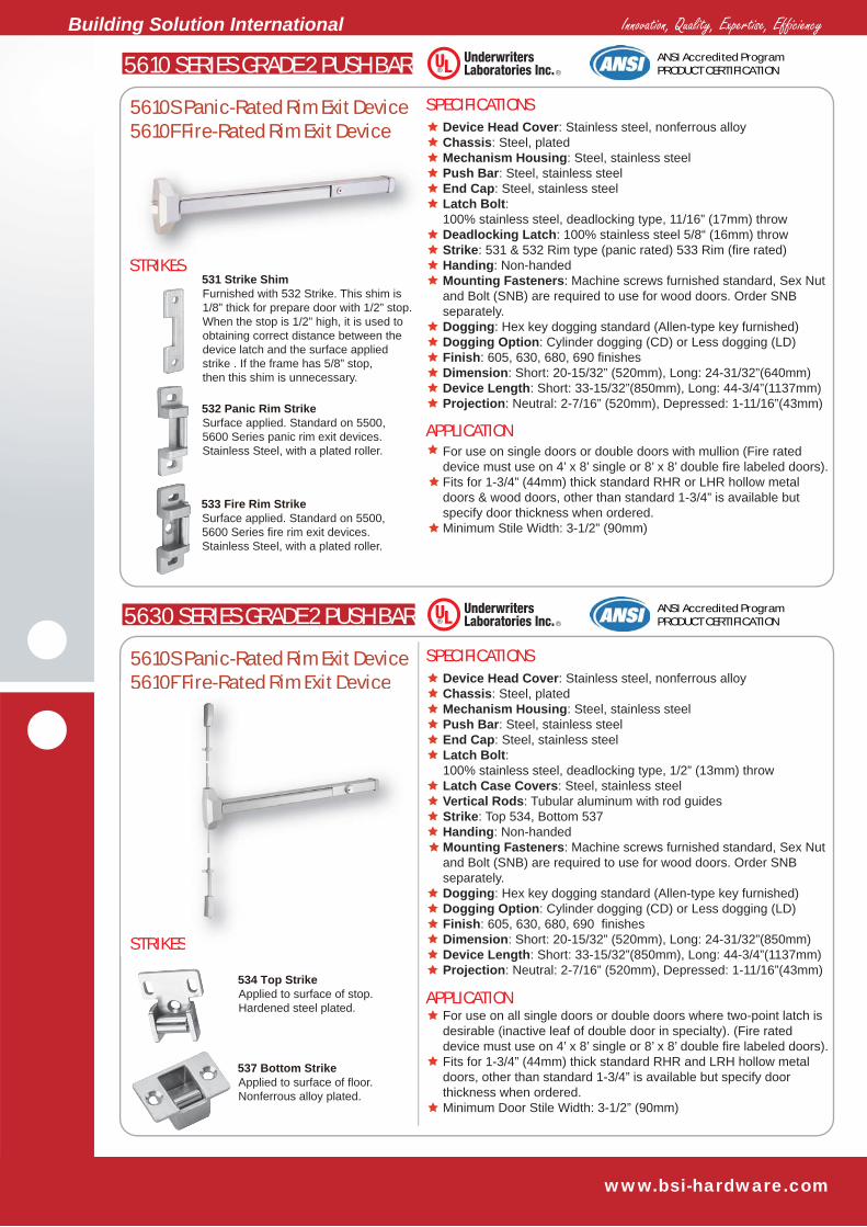
5610S Panic-Rated Rim Exit Device5610F Fire-Rated Rim Exit Device
5610S Panic-Rated Rim Exit Device5610F Fire-Rated Rim Exit Device
Furnished with 532 Strike. This shim is 1/8” thick for prepare door with 1/2” stop. When the stop is 1/2” high, it is used to obtaining correct distance between the device latch and the surface applied strike . If the frame has 5/8” stop,then this shim is unnecessary.
531 Strike Shim
Surface applied. Standard on 5500,5600 Series panic rim exit devices. Stainless Steel, with a plated roller.
532 Panic Rim Strike
Surface applied. Standard on 5500,5600 Series fire rim exit devices. Stainless Steel, with a plated roller.
533 Fire Rim Strike
Applied to surface of stop. Hardened steel plated.
534 Top Strike
Applied to surface of floor. Nonferrous alloy plated.
537 Bottom Strike
5610 SERIES GRADE 2 PUSH BAR
SPECIFICATIONS
APPLICATION
Device Head Cover: Stainless steel, nonferrous alloy Chassis: Steel, plated Mechanism Housing: Steel, stainless steel Push Bar: Steel, stainless steel End Cap: Steel, stainless steel Latch Bolt: 100% stainless steel, deadlocking type, 11/16” (17mm) throw Deadlocking Latch: 100% stainless steel 5/8“ (16mm) throw Strike: 531 & 532 Rim type (panic rated) 533 Rim (fire rated) Handing: Non-handed Mounting Fasteners: Machine screws furnished standard, Sex Nut and Bolt (SNB) are required to use for wood doors. Order SNB separately. Dogging: Hex key dogging standard (Allen-type key furnished) Dogging Option: Cylinder dogging (CD) or Less dogging (LD) Finish: 605, 630, 680, 690 finishes Dimension: Short: 20-15/32” (520mm), Long: 24-31/32”(640mm) Device Length: Short: 33-15/32”(850mm), Long: 44-3/4”(1137mm) Projection: Neutral: 2-7/16” (520mm), Depressed: 1-11/16”(43mm)
For use on single doors or double doors with mullion (Fire rated device must use on 4’ x 8’ single or 8’ x 8’ double fire labeled doors). Fits for 1-3/4” (44mm) thick standard RHR or LHR hollow metal doors & wood doors, other than standard 1-3/4” is available but specify door thickness when ordered. Minimum Stile Width: 3-1/2” (90mm)
Device Head Cover: Stainless steel, nonferrous alloy Chassis: Steel, plated Mechanism Housing: Steel, stainless steel Push Bar: Steel, stainless steel End Cap: Steel, stainless steel Latch Bolt: 100% stainless steel, deadlocking type, 1/2” (13mm) throw Latch Case Covers: Steel, stainless steel Vertical Rods: Tubular aluminum with rod guides Strike: Top 534, Bottom 537 Handing: Non-handed Mounting Fasteners: Machine screws furnished standard, Sex Nut and Bolt (SNB) are required to use for wood doors. Order SNB separately. Dogging: Hex key dogging standard (Allen-type key furnished) Dogging Option: Cylinder dogging (CD) or Less dogging (LD) Finish: 605, 630, 680, 690 finishes Dimension: Short: 20-15/32” (520mm), Long: 24-31/32”(850mm) Device Length: Short: 33-15/32”(850mm), Long: 44-3/4”(1137mm) Projection: Neutral: 2-7/16” (520mm), Depressed: 1-11/16”(43mm)
ANSI Accredited ProgramPRODUCT CERTIFICATION
5630 SERIES GRADE 2 PUSH BAR
SPECIFICATIONS
APPLICATION
STRIKES
For use on all single doors or double doors where two-point latch is desirable (inactive leaf of double door in specialty). (Fire rated device must use on 4’ x 8’ single or 8’ x 8’ double fire labeled doors). Fits for 1-3/4” (44mm) thick standard RHR and LRH hollow metal doors, other than standard 1-3/4” is available but specify door thickness when ordered. Minimum Door Stile Width: 3-1/2” (90mm)
ANSI Accredited ProgramPRODUCT CERTIFICATION
STRIKESSTRIKES
5610F Fire-Rated Rim Exit Device
STRIKES

Innovation, Quality, Expertise, Efficiency Building Solution International
www.bsi-hardware.com
5510S Panic-Rated Rim Exit Device
5530S Panic-Rated SVR Exit Device
Furnished with 532 Strike.This shim is 1/8” thick for prepare door with 1/2” stop. When the stop is 1/2” high, it is used to obtaining correct distance between the device latch and the surface applied strike . If the frame has 5/8” stop,then this shim is unnecessary.
531 Strike Shim
Surface applied. Standard on 5500,5600 Series panic rim exit devices. Stainless Steel, with a plated roller.
532 Panic Rim Strike
Applied to surface of stop. Hardened steel plated.
534 Top Strike
Applied to surface of floor. Nonferrous alloy plated.
537 Bottom Strike
5510 SERIES GRADE 2 PUSH BAR
SPECIFICATIONS
APPLICATION
Device Head Cover: Stainless steel, nonferrous alloy Chassis: Steel, plated Mechanism Housing: Steel, stainless steel Push Bar: Steel, stainless steel End Cap: Steel, stainless steel Latch Bolt: 100% stainless steel, deadlocking type, 11/16” (17mm) throw Deadlocking Latch: 100% stainless steel 5/8“ (16mm) throw Strike: 531 & 532 Rim type Handing: Non-handed Mounting Fasteners: Machine screws furnished standard, Sex Nut and Bolt (SNB) are required to use for wood doors. Order SNB separately. Dogging: Hex key dogging standard (Allen-type key furnished) Dogging Option: Cylinder dogging (CD) or Less dogging (LD) Finish: 605, 630, 680, 690 finishes Dimension: Short: 20-15/32” (520mm), Long: 24-31/32”(640mm) Device Length: Short: 33-15/32”(850mm), Long: 44-3/4”(1137mm) Projection: Neutral: 2-7/16” (520mm), Depressed: 1-11/16”(43mm)
For use on single doors or double doors with mullion (Fire rated device must use on 4’ x 8’ single or 8’ x 8’ double fire labeled doors). Fits for 1-3/4” (44mm) thick standard RHR or LHR hollow metal doors & wood doors, other than standard 1-3/4” is available but specify door thickness when ordered. Minimum Stile Width: 2-1/2” (63mm)
Device Head Cover: Stainless steel, nonferrous alloy Chassis: Steel, plated Mechanism Housing: Steel, stainless steel Push Bar: Steel, stainless steel End Cap: Steel, stainless steel Latch Bolt: 100% stainless steel, deadlocking type, 1/2” (13mm) throw Latch Case Covers: Steel, stainless steel Vertical Rods: Tubular aluminum with rod guides Strike: Top 534, Bottom 537 Handing: Non-handed Mounting Fasteners: Machine screws furnished standard, Sex Nut and Bolt (SNB) are required to use for wood doors. Order SNB separately. Dogging: Hex key dogging standard (Allen-type key furnished) Dogging Option: Cylinder dogging (CD) or Less dogging (LD) Finish: 605, 630, 680, 690 finishes Dimension: Short: 20-15/32” (520mm), Long: 24-31/32”(850mm) Device Length: Short: 33-15/32”(850mm), Long: 44-3/4”(1137mm) Projection: Neutral: 2-7/16” (520mm), Depressed: 1-11/16”(43mm)
ANSI Accredited ProgramPRODUCT CERTIFICATION
5530 SERIES GRADE 2 PUSH BAR
SPECIFICATIONS
APPLICATION
STRIKES
For use on all single doors or double doors where two-point latch is desirable (inactive leaf of double door in specialty). (Fire rated device must use on 4’ x 8’ single or 8’ x 8’ double fire labeled doors). Fits for 1-3/4” (44mm) thick standard RHR and LRH hollow metal doors, other than standard 1-3/4” is available but specify door thickness when ordered. Minimum Door Stile Width: 2-1/2” (63mm)
ANSI Accredited ProgramPRODUCT CERTIFICATION
STRIKESSTRIKES
5510S Panic-Rated Rim Exit Device
5530S Panic-Rated SVR Exit Device
STRIKES

Innovation, Quality, Expertise, Efficiency Building Solution International
www.bsi-hardware.com
SINGLE DOOR DOUBLE DOOR WITH MULLION
One Rim Device is the poplular choice for use on single outwardlyswing door use. In this appliction any device may be used.
Rim Device (or MortiseLock Device) and Surface Vertical RodDevice combination -Smae direction
Two Surface Vertical Rod(SVR) or Concealed VerticalRod(CVR) Devices - double egress. Overlapping astragalrequired or not required, option.
Use this diagram to determine the hand of door.
Two Surface Vertical Rod(SVR) or Concealed Vertical Rod (CVR) - same direction. Overlapping astragal is not required.
Two rim Devices withmullion - same direction
APPLICATION
RHR LHR
MULLION
OUTSIDE OF DOOR
DOUBLE DOOR
DOUBLE DOOR REVERSE OPENING DOOR HANDING
DOUBLE DOOR

Innovation, Quality, Expertise, Efficiency Building Solution International
www.bsi-hardware.com
1. Auxiliary Guarded Latch: Stainless steel 2. Latch Bolt, 3/4” (19mm) throw: Stainless steel 3. Chassis Cover (or called Head Cover): Nonferrous or stainless steel 4. Chassis: Plated steel 5. Push Bar: Extruded aluminum 6. Push Bard End Cap: Nonferrous alloy 7. Bush Bar Trim: Brass, stainless steel, steel 8. Mechanism Housing (or device body): Extruded aluminum
9. Dogging Plated (or called rear cover): Extruded aluminum10. End Cap: Nonferrous alloy11. Top Latch, 5/8” (16mm) throw: Stainless steel12. Latch Assembly Cover: Brass, stainless steel, steel13. Top Vertical Rod & Rod Guide: Strong aluminum tube14. Bottom Vertical Rod: Strong aluminum tube15. End Cap Bracket: Plated steel16. Bottom Latch, 5/8” (16mm) throw: Stainless steel
Wide Stile Exit Device
Narrow Stile Exit Device
Parts Material
11
12
13
4
14
16
5
15
8
GRADE 1 PUSH BAR DIMENSIONS
2"(51m m )
Short :18-3/8"(462m m )Long:21-21/32"(550m m )
2-1/4"(57m m )
Neut ral :3-1/16"(78m m )Depressed :2-19/32"(66m m )Project ion
8-1/32"(204mm)
3-7/32"(82mm)
3-7/32"(82mm)
5/8"(16mm)
1
2
36 7 9
10
8-1/32"(204mm)
2-13/32"(61mm)
2-25/32"(71mm)
Device Length Short:33"(838mm)Long:45"(1143mm)
1. Auxiliary Guarded Latch: Stainless steel 2. Latch Bolt, 3/4” (19mm) throw: Stainless steel 3. Chassis Cover (or called Head Cover): Nonferrous or stainless steel 4. Chassis: Plated steel 5. Push Bar: Extruded aluminum 6. Push Bard End Cap: Nonferrous alloy 7. Bush Bar Trim: Brass, stainless steel, steel 8. Mechanism Housing (or device body): Extruded aluminum
9. Dogging Plated (or called rear cover): Extruded aluminum10. End Cap: Nonferrous alloy11. Top Latch, 5/8” (16mm) throw: Stainless steel12. Latch Assembly Cover: Brass, stainless steel, steel13. Top Vertical Rod & Rod Guide: Strong aluminum tube14. Bottom Vertical Rod: Strong aluminum tube15. End Cap Bracket: Plated steel16. Bottom Latch, 5/8” (16mm) throw: Stainless steel
Parts Material
16
5
15
8
2"(51mm)
Short:18-3/8"(462mm)Long:21-21/32"(550mm)
2-1/4"(57mm)
Neutral :3-1/16"(78mm)Depressed:2-19/32"(66mm)Projection
8-1/32"
1-17/32" (39mm)
3-17/32" (90mm)
(204mm)2-13/32"(61mm)
Device Length Short:33"(838mm)Long:45"(1143mm)
8-1/32"(204mm)
3-7/32"(82mm)
3-7/32"(82mm)
5/8"(16mm)
1
2
36 7 9
10
11
12
13
4
14

Innovation, Quality, Expertise, Efficiency Building Solution International
www.bsi-hardware.com
STRIKES
Narrow Stile Wide Stile Exit Device8
13 3
4 5 6
6
4 7
1
22
9
10
11
12
13
14
15
APPLICATION
Non-Fire Rated Keyed Removable Mullion, Model 7100
GRADE 2 PUSH BAR DIMENSIONS
Mullion Tube: 2” (51mm) wide x 3“ (76mm) deep, with wall thickness of 1/8” (3mm), 11 Gauge Steel Tube Mullion Size: 7’ (2134mm), 8’ (2438mm) or 10’ (3048mm) three sizes, mullion may be field cut to fit proper size Rim Cylinder: Use a 1-1/4“ solid brass 6-pin rim cylinder, model 426 or interchangeable core, model 308, sold separately Top Bracket: Steel, using the key allows to removed the mullion in seconds. Mullion can be easily locked on the top bracket without using the key. Bottom Bracket: Steel, fixed by 4 hex bolts with nonferrous anchors Shims: 1/2” (13mm) and 5/8“ (16mm) shims included Fasteners: Each mullion includes: 2 Flat Head Machine Screws, #5/16”-18 x 1-1/2“ plated steel 4 Flat Head Machine Screws, #5/16”-18 x 5/8“ plated steel 4 Hex Head Machine Screws, # 5/16”-18 x 1-1/4“ , plated steel 4 Exoansion Anchors, 5/8” dia. x 7/8“ long, nonferrous alloy Strike: Use two standard Rim Strikes (801), not included Finish: Gray baked powder coating only
BSI 7000 Series Keyed Removable Mullions are used with 5000 Series Rim Exit Devices on non-fire or fire rated pairs of doors. The 7100 Mullion is easy and fast removing from the top bracket by a simple operation of the rim cylinder when a clear, unobstructed large opening is required.
AUXILIARY HARDWARE-MULLION
SPECIFICATIONS
1. Auxiliary Guarded Latch 2. Latch Bolt 3. Chassis Cover (or called Head Cover) 4. Push Bar 5. Dogging Plate 6. End Cap 7. Mechanism Housing(or called Device body) 8. Top Latch
9. Latch Assembly Cover10. Top Vertical Rod11. Rod Guide12. Chassis13. End Cap Bracket14. Bottom Vertical Rod15. Bottom Latch
Parts Name
8-1/32"(204mm)
3-7/32"(82mm)
3-7/32"(82mm)
5/8"(16mm)
6-7/32"(158mm)
1-31/32"(50mm)
Device Length Short:33-15/32”(850mm)Long:44-3/4"(1137mm)
1-13/16" (46mm)
2-23/32" (69mm)
6-7/32"(148mm)
1-5/16" (33mm)
2-23/32" (69mm)
2"(51mm)
Short:18-3/8"(462mm)Long:21-21/32"(550mm)
2-1/4"(57mm)
Neutral :3-1/16"(78mm)Depressed :2-19/32"(66mm)Projection
Rim Strike801
Top Bracket752
Top Bracket755

Innovation, Quality, Expertise, Efficiency Building Solution International
www.bsi-hardware.com
STRIKES
Fire-Rated Keyed Removable Mullion, Model 7200
Surface Mounted Door Coordinator- SNC SERIES
AUXILIARY HARDWARE-MULLION
SPECIFICATIONS Mullion Tube: 2” (51mm) wide x 3“ (76mm) deep, with wall thickness of 1/8” (3mm), 11 Gauge Steel Tube Mullion Size: 7’ (2134mm), 8’ (2438mm) two sizes, mullion may be field cut to fit proper size Rim Cylinder: Use a 1-1/4“ solid brass 6-pin rim cylinder, model 426 or interchangeable core, model 308, sold separately. Top Bracket: Steel, using the key allows to removed the mullion in seconds. Mullion can be easily locked on the top bracket without using the key. Bottom Bracket: Stainless Steel, fiexed by 4 hex bolts with stainless steel anchors Shims: 1/2” (13mm) and 5/8“ (16mm) shims included Fasteners: Each mullion includes: 2 Flat Head Machine Screws, #5/16”-18 x 1-1/2“ plated steel 4 Flat Head Machine Screws, #5/16”-18 x 5/8“ plated steel 4 Hex Head Machine Screws, # 5/16”-18 x 1-1/4“ , plated steel 4 Exoansion Anchors, 5/8” dia. x 7/8“ long, steel Strike: Use two sets Mullion Strikes (688), & Strike Hooks (689), sold separately Finish: Gray baked powder coating only
A door coordinator adapted to control the closing of a pair of swinging doors constituted by an active door and an inactive door hung to swing into and out of closed position beneath a head frame. As shown in drawing the Active Door Hold Open Lever is near to the active door open until the inactive Door Trigger is released to the retracted position by closing the inactives doors.
AUXILIARY HARDWARE-COORDINATOR
APPLICATION
MODEL NUMBER & SIZE
DOOR DOOR
STRIKE MULLION
Top Bracket752F
Mullion Strike688
Mullion Strike689
Top Bracket755F
CoordinatorMechanism
Active Door Hold Open Lever
MB2Mounting Bracket
Door Trigger
MB3Mounting Bracket
Filler Bar
Innovation, Quality, Expertise, Efficiency Building Solution International
www.bsi-hardware.com
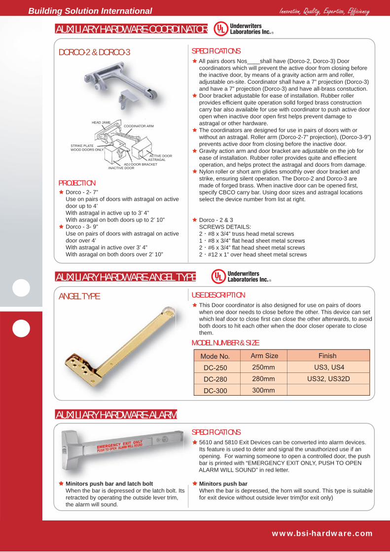
DORCO-2 & DORCO-3
ANGEL TYPE
AUXILIARY HARDWARE-COORDINATOR
SPECIFICATIONS All pairs doors Nos____shall have (Dorco-2, Dorco-3) Door coordinators which will prevent the active door from closing before the inactive door, by means of a gravity action arm and roller, adjustable on-site. Coordinator shall have a 7” projection (Dorco-3) and have a 7” projection (Dorco-3) and have all-brass constuction. Door bracket adjustable for ease of installation. Rubber roller provides efficient quite operation solld forged brass construction carry bar also available for use with coordinator to push active door open when inactive door open first helps prevent damage to astragal or other hardware. The coordinators are designed for use in pairs of doors with or without an astragal. Roller arm (Dorco-2-7” projection), (Dorco-3-9”) prevents active door from closing before the inactive door. Gravity action arm and door bracket are adjustable on the job for ease of installation. Rubber roller provides quite and effiecient operation, and helps protect the astragal and doors from damage. Nylon roller or short arm glides smoothly over door bracket and strike, ensuring silent operation. The Dorco-2 and Dorco-3 are made of forged brass. When inactive door can be opened first, specify CBCO carry bar. Using door sizes and astragal locations select the device number from list at right.
Dorco - 2 & 3 SCREWS DETAILS: 2‧#8 x 3/4” truss head metal screws 1‧#8 x 3/4” flat head sheet metal screws 2‧#6 x 3/4” flat head sheet metal screws 2‧#12 x 1” over head sheet metal screws
Dorco - 2- 7” Use on pairs of doors with astragal on active door up to 4’ With astragal in active up to 3’ 4” With asragal on both doors up to 2’ 10” Dorco - 3- 9” Use on pairs of doors with astragal on active door over 4’ With astragal in active over 3’ 4” With asragal on both doors over 2’ 10”
This Door coordinator is also designed for use on pairs of doors when one door needs to close before the other. This device can set which leaf door to close first can close the other afterwards, to avoid both doors to hit each other when the door closer operate to close them.
AUXILIARY HARDWARE-ANGEL TYPE
USE DESCRIPTION
5610 and 5810 Exit Devices can be converted into alarm devices. Its feature is used to deter and signal the unauthorized use if an opening. For warning someone to open a controlled door, the push bar is printed with “EMERGENCY EXIT ONLY, PUSH TO OPEN ALARM WILL SOUND” in red letter. Minitors push bar When the bar is depressed, the horn will sound. This type is suitable for exit device without outside lever trim(for exit only)
Minitors push bar and latch bolt When the bar is depressed or the latch bolt. Its retracted by operating the outside lever trim, the alarm will sound.
SPECIFICATIONS
MODEL NUMBER & SIZE
AUXILIARY HARDWARE-ALARM
PROJECTION
HEAD JAMECOODINATOR ARM
ACTIVE DOORASTRAGAL
ADJ DOOR BRACKETINACTIVE DOOR
STRIKE PLATEWOOD DOORS ONLY
Minitors push bar and latch bolt
SP

Innovation, Quality, Expertise, Efficiency Building Solution International
www.bsi-hardware.com
AUXILIARY HARDWARE-FLUSH BOLT
AUTOMATIC FLUSH BOLTS
MANUAL FLUSH BOLTS
Model No.: FB610M (for metal doors), FB610W (for wood doors) Non-handed. Label: A (3-Hour Fire Exit Hardware). Face Plate: FB610M - 1” x 6-3/4“, FB610W - 1” x 8-1/2“ Finish: US3, US4, US26, US26D, US32, US32D Use on inactive leaf of double wood / hollow metal doors. Full automatic, when active door is opened, inactive door is free. Automatically locks inactive door under high fire/heat conditions. Used on the top and bottom of inactive door. If use one unit for top side only, it has to combined with auxiliary latch which replaces the bottom bolts
Model No.: FB100 Devices are ANSI A156.16 Length of Bolt Rod: 10-1/4” with 5/8” throw Bolt diameter: 1/2” Forged brass body, aluminum faceplate Non-handed. Easy finger grip lever action and easy installation. Tension spring action holds solidly in position. Plunger supplied with milled surface on side which fits into a matching guild prevents bolt from turning and unscrewing Lengths are from center of bolt Mechanism when bolt head is retracted. Finsh: 605, 606, 625, 626 For dust-proof strike DP005, is available with a bottom manual flush bolt.
A Fire latch bolt is used with a pair of UL listed fire rate LBR exit devices, it includes a spring loaded and a stainless steel bolt which installs in the lower door edge inside to replace bottom vertical rods of two SVR exit devices on a double door. The UL listed fire latch bolt is a temperature-actuated bolt that is designed to release from one door leaf and engage the other door when the temperature exceed the rating of the fusible link during a fire. When the fire latch bolt releases to connect the opposite door leaf, it keeps the doors in alignment and closed during the fire.
MANUAL FLUSH BOLTS Model No.: FB510M-For Metal Doors FB510W-For Wood Doors Non-handed Label: A (3-Hour Fire Exit Hardware). Face Plate: FB610M - 1” x 6-3/4“, FB610W - 1” x 8-1/2“ Finish: US3, US4, US26, US26D, US32, US32D Use at top of door only, an automatic flush bolt combined use at bottom of door. Or a constant latching flush bolt combines with the auxuliary fire latch, providing significant reduction in door prep and eliminating floor prep entirely When inactive door closes, flush bolt is automatucally latched
FIRE LATCH BOLT
SPECIFICATIONS
ANSI Accredited ProgramPRODUCT CERTIFICATION
FB610M FB610W FB510M FB100
DP005
Less Dogging(LD) Less Dogging is available on all 5000 Series Panic Exit Devices when users want to remove the dogging option. Cylinder Dogging(CD) Cylinder Dogging is available on all 5000 Series Panic Exit Device to repalce the standard hex key dogging. Unit requires a standard 1-1/4” (32mm) mortise cylinder with a straight cam Cylinder Dogging Kit(CDK) For field conversion, a cylinder dogging conversion kit is available. It cannot be added to fire exit hardware.
DOGGING OPTION
SPECIFICATIONSLess Dogging
Cylinder Dogging

Innovation, Quality, Expertise, Efficiency Building Solution International
www.bsi-hardware.com
3-5/16”(85mm)
1-7/32”(31mm)
3-5/16”(85mm)
1-7/32”(31mm)
2”(51mm)
31/32”(25mm)
2-3/4”
(70mm)
815(panic)
2-3/4”
(70mm)
2”(51mm)
31/32”(25mm)
825(fire)
862
618
623630
Furnished with 532 Strike.This shim is 1/8” thick for prepare door with 1/2” stop. It is used to obtain correct distance between the device latch and the surface applied strike when the stopis 1/2” high. If the frame has 5/8” stop,then this shim is unnecessary.
531 Strike Shim
Surface applied. Standard on 5500,5600 Series panic rim exit devices. Satinless Steel, with a plated roller.
532 Panic Rim Strike
Surface applied. Standard on 5500,5600 Series fire rim exit devices. Satinless Steel, with a plated roller.
533 Fire Rim Strike
Applied to surface of stop. Hardened steelm plated.
534 Top Strike
Not includedwith device,sold separately
720
Applied to surface of floor. Nonferrous alloy, plated.
537 Bottom Strike
689688
STRIKE
Rim DEVICES USERim Strikes Top Strikes
Double Door Strikes Sex Nuts and Bolts
Bottom Strikes(Floor Strikes)
Threshold Strikes
Mullion Strikes
STRIKE FOR GRADE 2 MORTISE DEVICE USE
OTHERS
Rim DEVICES USE
801(panic)
802(Fire)
Standard for5710S5810S
Standard topstrike for5730S5830S
Standard floorstrike for5730S5830S5750S5850S
Standard floorstrike for5730F5830F5750F5850F
Optionalfloor strikefor usingthresholdopenings
SNB - 1-3/4” thickness door use (Standard door)SNB - 2-1/4” thickness door useSNB - 2-1/2” thickness door use
Standard topstrike for5730F5830F
Standard topstrike for5750S5850S
Standard topstrike for5750F5850F
Standard for5710S5810S
Standard forpanic ratedmullion 7200,LBR5830
Projection: 13/16” (21mm)
Projection: 29/32” (23mm)
Projection: 1-1/8” (29mm)
Mortise: 2-1/4” (29mm)
Mortise: 2-1/4” (29mm)
Mortise: 3/4” (19mm)
Projection: 13/16” (21mm)
Projection: 7/8” (22.5mm)
3-5/16”(85mm)
1-7/32”(31mm)
1-13/16”(46mm)
2-15/32”(63mm)
9/16”(14mm) 25/32”
(20.6mm)
2-1/21”(63.5mm)
1-1/8” (29mm)
822(fire)
1-1/8”(29mm)
2-1/21”(63.5mm)
812(panic)
813(panic)
823(fire)
15/16”(24mm)
15/16”(24mm)
2-1/2”(64mm)
1-1/4”(32mm)
4-13/16”(123mm)
1-7/32”(31mm)
3-5/16”(85mm)
1-7/32”(31mm)
818(panic) 828(fire)For use on 1-3/4”standard or 2-1/4” thickness single door,and 2-1/4” doubledoor with overlapping astragal and coordinator
3-7/32”(82mm)
3/4”(19mm)
1”(25.5mm)
1-1/4”(32mm)
1-9/16”(40mm)
1-7/32”(31mm)

Innovation, Quality, Expertise, Efficiency Building Solution International
www.bsi-hardware.com
Model 58 and 57 Series Escutcheon Levers
Features
Models and Functions
Non-handed, easy install with exit device. Easy operating lever handle allows coverient one hand operation. Popular 8 finishes for users and architects choosing: US3(605), US4(606), US10(612), US10B(613), US26(625), US26D(626), US28(689), and US32D(630). Trim has 4 through-bolts to the device chassis directly for more security and durability. It fits 1-3/4” (44mm) door standard. For 2” (51mm), 2-1/4” (57mm) thick door or the shim-mounted exit device, specify the door thickness when ordering. Cluth freewheeling design. The lever rotates when the door is locked preventing excessive force from being applied to the horizontal lever. This designed feature can decrease the lever to be broken or damaged.
When need to meet key requirement, the trims may receive cylinders from other manufactures. Cylinder is not furnished standard. Specify cylinder type (RC - Regular Cylinder, IC - Interchangeable Core, NC - No Cylinder) when the cylinder is required. The 58E Series trims, which are used for mortise lock exit devices only, not available to be ordered individually. Any one trim must be packed together with a mortise lock exit device when ordered.
ELECTRIC LEVER OPTION Failsecure, field reversible to failsefe 12/24 VDC @ 600/300 mA
Operation Options
Function
Trim Designation
5820S-36-58E-17-A-RC-626
Escutchoen Plate
Cylinder Type
ANSI Function
Model Number & Use
(Dummy trim is not recommended for fire device)
Classroom
(E)58L01A
E58L01A
58E01A
57L01A
1/4” Mortise
Device model No. Finsih code
Lever designFunction codeCylinder type A - Classroom
B - PassageC - StoreroomD - Dummy
Device lengthTrim model No.
Rim
08 14 03 02
57L01B 57L01C 57L01D
58E01B
For 5800 Series Rim, Surface / Concealed Vertical Rod, LBR Exit Device Use
For 5800 Series Mortise Lock Exit Devices Use Only
For 5700 Series Rim, Surface / Concealed Vertical Rod, LBR Exit Device Use
8-27/32” x 2-15/16” x 15/16” (255mm x 75mm x 24mm)
58L01B 58L01C
58E01C
58L01D
58E01D
CylinderEscutcheon Lever
BlankEscutcheon Lever
Night LatchEscutcheon Lever
DummyEscutcheon Lever
Passage Storeroom Dummy
Key Always & Unlocks Lever
Lever Always Active (No Cylinder)
Key Retracts Latchbolt (Rigid Lever)
Pull When Dogged (Rigid Lever)
DEVICE OUTSIDE TRIMS
{

Innovation, Quality, Expertise, Efficiency Building Solution International
www.bsi-hardware.com
5820S-36-87E-4A-RC-626Device model No. Finsih code
Function codeCylinder type A - Classroom
B - PassageC - Night LatchD - Dummy
Device lengthTrim model No. {
Model 87P and 87E Series Pull Plates - For wide S le Exit Device useFeatures
Models and Functions
Non-handed, easy install with exit device. Popular 8 finishes for users and architects choosing: US3(605), US4(606), US10(612), US10B(613), US26(625), US26D(626), US28(689), and US32D(630). Trim has through-bolt to the device chassis directly for more security and durability. It fits 1-3/4” (44mm) door standard. For 2” (51mm), 2-1/4” (57mm) thick door or the shim-mounted exit device, specify the door thickness when ordering.
When need to meet key requirement, the trim may receive cylinders from other manufactures. Cylinder is not furnished standard. Specify cylinder type (RC - Regular Cylinder, IC - Interchangeable Core, NC - No Cylinder) when the cylinder is required. The 87E Series trims, which are used for mortise lock exit devices only, not available to be ordered individually. Any one trim must be packed together with a mortise lcok exit device when ordered.
To Inquire or Order for 87P Series Tirms Specify model series no., lever design No., function code (A, B, C, D), cylinder type and finish code. For example: 87P-6ARC-626
Operation Options
Function
Trim Designation
Escutchoen Plate
Cylinder Type
ANSI Function
Model Number & Use
(Dummy trim is not recommended for fire device)
Classroom
87P-5A
87P-6A
87E-4A
1/4” Mortise Rim
08 14 03 02
87E-4B 87E-4C 87E-4D
87P-6B
For 5800 Series Rim, Surface Vertical Rod, and LBR Type Exit Device Use
For 5800 Concealed Vertical Rod Type Exit Devices Use
For 5800 Mortise Lock Exit Devices Use Only
14-11/16” x 3” x 3/32” (373mm x 76mm x 2mm)
87P-5B 87P-5C
87P-6C
87P-5D
87P-6D
Cylinder Pull Plate with Thumb piece
Blank Pull Platewith Thumb piece Cylinder Pull Plate Dummy Pull Plate
Passage Night Latch Dummy
Key Locks & Unlocks Thumb piece
T-piece Always Active (No Cylinder)
Key Retracts Latchbolt
Pull When Dogged
DEVICE OUTSIDE TRIMS
Innovation, Quality, Expertise, Efficiency Building Solution International
www.bsi-hardware.com
Finsih code
Function codeCylinder type
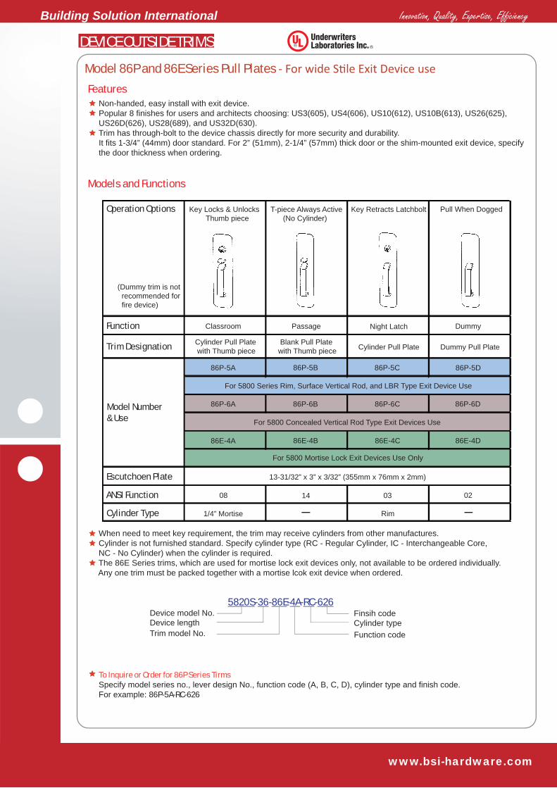
5820S-36-86E-4A-RC-626Device model No.Device lengthTrim model No.
Model 86P and 86E Series Pull Plates - For wide S le Exit Device useFeatures
Models and Functions
Non-handed, easy install with exit device. Popular 8 finishes for users and architects choosing: US3(605), US4(606), US10(612), US10B(613), US26(625), US26D(626), US28(689), and US32D(630). Trim has through-bolt to the device chassis directly for more security and durability. It fits 1-3/4” (44mm) door standard. For 2” (51mm), 2-1/4” (57mm) thick door or the shim-mounted exit device, specify the door thickness when ordering.
When need to meet key requirement, the trim may receive cylinders from other manufactures. Cylinder is not furnished standard. Specify cylinder type (RC - Regular Cylinder, IC - Interchangeable Core, NC - No Cylinder) when the cylinder is required. The 86E Series trims, which are used for mortise lock exit devices only, not available to be ordered individually. Any one trim must be packed together with a mortise lcok exit device when ordered.
To Inquire or Order for 86P Series Tirms Specify model series no., lever design No., function code (A, B, C, D), cylinder type and finish code. For example: 86P-5A-RC-626
Operation Options
Function
Trim Designation
Escutchoen Plate
Cylinder Type
ANSI Function
Model Number & Use
(Dummy trim is not recommended for fire device)
Classroom
86P-5A
86P-6A
86E-4A
1/4” Mortise Rim
08 14 03 02
86E-4B 86E-4C 86E-4D
86P-6B
For 5800 Series Rim, Surface Vertical Rod, and LBR Type Exit Device Use
For 5800 Concealed Vertical Rod Type Exit Devices Use
For 5800 Mortise Lock Exit Devices Use Only
13-31/32” x 3” x 3/32” (355mm x 76mm x 2mm)
86P-5B 86P-5C
86P-6C
86P-5D
86P-6D
Cylinder Pull Plate with Thumb piece
Blank Pull Platewith Thumb piece Cylinder Pull Plate Dummy Pull Plate
Passage Night Latch Dummy
Key Locks & Unlocks Thumb piece
T-piece Always Active (No Cylinder)
Key Retracts Latchbolt
Pull When Dogged
DEVICE OUTSIDE TRIMS

Innovation, Quality, Expertise, Efficiency Building Solution International
www.bsi-hardware.com
Finsih code
Function codeCylinder type A - Classroom
B - PassageC - Night LatchD - Dummy{
5730S-36-85E-4A-RC-626Device model No.Device lengthTrim model No.
Model 85P and Series Pull Plates - For Narrow S le Exit Device useFeatures
Models and Functions
Non-handed, easy install with exit device. Popular 8 finishes for users and architects choosing: US3(605), US4(606), US10(612), US10B(613), US26(625), US26D(626), US28(689), and US32D(630). Trim has through-bolt to the device chassis directly for more security and durability. It fits 1-3/4” (44mm) door standard. For 2” (51mm), 2-1/4” (57mm) thick door or the shim-mounted exit device, specify the door thickness when ordering.
When need to meet key requirement, the trim may receive cylinders from other manufactures. Cylinder is not furnished standard. Specify cylinder type (RC - Regular Cylinder, IC - Interchangeable Core, NC - No Cylinder) when the cylinder is required.
To Inquire or Order for 85P Series Tirms Specify model series no., lever design No., function code (A, B, C, D), cylinder type and finish code. For example: 85P-3A-RC-626
Operation Options
Function
Trim Designation
Escutchoen Plate
Cylinder Type
ANSI Function
Model Number & Use
(Dummy trim is not recommended for fire device)
Classroom
85P-3A
85P-4A
1/4” Mortise Rim
08 14 03 02
86P-6B
For 5700 Series Rim, Surface Vertical Rod Type Exit Device Use
For 5700 Concealed Vertical Rod Type Exit Devices Use
11-13/16” x 1-25/32” x 3/32” (300mm x 45mm x 2mm)
85P-3B 85P-3C
86P-6C
85P-3D
86P-6D
Cylinder Pull Plate with Thumb piece
Blank Pull Platewith Thumb piece Cylinder Pull Plate Dummy Pull Plate
Passage Night Latch Dummy
Key Locks & Unlocks Thumb piece
T-piece Always Active (No Cylinder)
Key Retracts Latchbolt
Pull When Dogged
DEVICE OUTSIDE TRIMS

Innovation, Quality, Expertise, Efficiency Building Solution International
www.bsi-hardware.com
5730S-36-84P-4A-RC-626Device model No. Finsih code
Function codeCylinder type A - Classroom
B - PassageC - Night LatchD - Dummy
Device lengthTrim model No. {
Model 84P and Series Pull Plates - For Narrow S le Exit Device useFeatures
Models and Functions
Non-handed, easy install with exit device. Popular 8 finishes for users and architects choosing: US3(605), US4(606), US10(612), US10B(613), US26(625), US26D(626), US28(689), and US32D(630). Trim has through-bolt to the device chassis directly for more security and durability. It fits 1-3/4” (44mm) door standard. For 2” (51mm), 2-1/4” (57mm) thick door or the shim-mounted exit device, specify the door thickness when ordering.
When need to meet key requirement, the trim may reveice cylinders from other manufactures. Cylinder is not furnished standard. Specify cylinder type (RC - Regular Cylinder, IC - Interchangeable Core, NC - No Cylinder) when the cylinder is required.
To Inquire or Order for 84P Series Tirms Specify model series no., lever design No., function code (A, B, C, D), cylinder type and finish code. For example: 84P-3A-RC-626
Operation Options
Function
Trim Designation
Escutchoen Plate
Cylinder Type
ANSI Function
Model Number & Use
(Dummy trim is not recommended for fire device)
Classroom
84P-3A
84P-4A
1/4” Mortise Rim
08 14 03 02
84P-6B
For 5700 Series Rim, Surface Vertical Rod Type Exit Device Use
For 5700 Concealed Vertical Rod Type Exit Devices Use
11-13/16” x 1-25/32” x 3/32” (300mm x 45mm x 2mm)
84P-3B 84P-3C
84P-6C
84P-3D
84P-6D
Cylinder Pull Plate with Thumb piece
Blank Pull Platewith Thumb piece Cylinder Pull Plate Dummy Pull Plate
Passage Night Latch Dummy
Key Locks & Unlocks Thumb piece
T-piece Always Active (No Cylinder)
Key Retracts Latchbolt
Pull When Dogged
DEVICE OUTSIDE TRIMS

Innovation, Quality, Expertise, Efficiency Building Solution International
www.bsi-hardware.com
#01 Lever #05 Lever #17 Lever #31 Lnob
OPTION LEVER DESIGN
Model 56P Series Escutcheon Levers
Features
Models and Functions
Non-handed, easy install with exit device. Provide 4 finishes for user and architects chossing: US3(605), US20A(690), US689, and US32D(630) Trim has through-bolt to the device chassis directly for more security and durability. It fits 1-3/4” (44mm) door standard. For 2” (51mm), 2-1/4” (57mm) thick door or the shim-mounted exit device, specify the door thickness when ordering. This series trim is Anti-Vandalism design that can prevent the lock from damaging when key locks the lever in rigid and horizontal position. The trim has four models to meet different functions use, see the chat below
Escutcheon made of steel or stainless steel, lever handle made of zinc alloy. When need to meet key requirement, the trim may receive cylinders from other manufactures. Cylinder is not furnished standard. Specify cylinder type (RC - Regular Cylinder, IC - Interchangeable Core, NC - No Cylinder) when the cylinder is required.
Operation Options
Function
Trim Designation
Escutchoen Plate
Cylinder Type
ANSI Function
Regular Type
Interchange Core Type
Mortise Cylinder Rim Cylinder
Model Number & Use
(Dummy trim is not recommended for fire device)
Classroom
56L01A
1/4” Mortise Rim
08 14 03 02
For 5610 Series Rim, 5630 Series Surface Vertical Rod
11-13/16” x 1-25/32” x 3/32” (300mm x 45mm x 2mm)
56L01B 56L01C 56L01D
CylinderEscutcheon Lever
BlankEscutheon Lever
Night LatchEscutheon Lever
DummyEscutheon Lever
Passage Soteroom Dummy
Key Locks & Unlocks Thumb piece
T-piece Always Active (No Cylinder)
Key Retracts Latchbolt
Pull When Dogged
DEVICE OUTSIDE TRIMS
CYLINDER OPTIONS

Innovation, Quality, Expertise, Efficiency Building Solution International
www.bsi-hardware.com
Model 56P and 54P Series Standard Pull Plates
Model 52R Series Raised-Lip Type Pull Plates
Cylinder is not furnished standard. When need to meet key requirement, the trims may receive cylinders from other manufactures. Specify cylinder type (RC - Regular Cylinder, IC - Interchangeable Core, NC - No Cylinder) when the cylinder is required. The face plates of these trims can made of steel or stainless steel, lever handles are made of zinc alloy. 52R & 56P Series trim can retrofit 1-3/4” steel doors prep for bored locks (pre ANSI A115.2). 55P & 56P Series trims furnish mounting through-bolts, 52R Series trim furnishes sex nuts and bolts (SNB). Supply US3(605), US32D(630), US20A(690), and US28(689) four finishes.
To Inquire or Order Specify model number, cylinder type, finish code, amd add door thicknesds if the door is thicker than standard. For example: 52R2A-RC-630
Trim Designation
Function
Operation
Escutchoen Plate
Cylinder Type
ANSI Function
Model Number forWide Stile Exit Device
Model Number forNrrow Stile Exit Device
Model Number forNrrow Stile Exit Device
Night Latch
56P3A
55P3A
52R2A
52R2B
56P3A
55P3A
Rim
03 02 10
55P3B
For 5610 Series Rim and 5630 Series SVR Exit Device Use
For 5510 Series Rim and 5530 Series SVR Exit Device Use
L7-11/16” x W3” x T1/8” (196mm x 76mm x 3mm)
Escutchoen Plate 56P Series - L11-13/16” x W3” x T3/32” (300mm x 76mm x 2mm)55P Series - L11-13/16” x W1-25/32” x T3/32” (300mm x 45mm x 2mm)
56P3B 56P3C
52R2A
For 5610 Series Rim and 5630 Series SVR Exit Device Use
52R2B 52R2C
55P3C
Key Retracts Latchbolt
Pull when dogged(Don’t use for Fire Device)
Cannot operate
Dummy Decor
Cylinder RL Type Pull Plate
Blank RL Type Pull Plate
Flat Plate(No Lips)
Trim Designation
Function
Operation
Night Latch
Key Retracts Latchbolt
Pull when dogged(Don’t use for Fire Device)
Cannot operate
Dummy Decor
Cylinder RL Type (With cylinder)
Dummy Pull Plate (without cylinder)
Flat Plate(without cylinder & grip)
DEVICE OUTSIDE TRIMS

Innovation, Quality, Expertise, Efficiency Building Solution International
www.bsi-hardware.com
5820S-36-SF8-17-A-RC-63Device model No. Finsih code
Lever designFunction codeCylinder type A - Classroom
B - PassageC - StoreroomD - Dummy
Device lengthTrim model No. {
Model SF8 and F8 Series Round Rose Levers
Features
Models and Functions
Non-handed, easy install with exit device. Easy operating lever handle allows convenient one hand operation. Provide 4 finishes for users and architects choosing: US3(605), US20A(690), US28(689), and US32D(630). Trim has through-bolt to the device chassis directly for more security and durability. The actuating shaft of this trim made of hardened steel bar, It fits 1-3/4” (44mm) door standard. For 2” (51mm), 2-1/4” (57mm) thick door or the shim-mounted exit device, specify the door thickness when ordering. Clutch freewheeling design. The lever roates when the door is locked preventing excessive force from being applied to the horizontal lever. This designed feature can decrease the lever to be broken or damaged.
Rose Trim made of steel or stainless steel, lever handle made of zinc alloy. When need to meet key requirement, the trim may receive cylinders from other manufactures. Cylinder is not furnished standard. Specify cylinder type (RC - Regular Cylinder, IC - Interchangeable Core, NC - No Cylinder) when the cylinder is required. SF8 Series trims can fit and cover turtle cutout of 1-3/4” steel doors prep for bored locks with lever handles (per ANSI/HMA 156.115).
To Inquire or Order for SF8 and F8Series Tirms Specify model series no., lever design No., function code (A, B, C, D), cylinder type and finish code. For example: SF8-17-A-RC-63
Operation Options
Function
Trim Designation
Dimensions
Cylinder Type
Model Number & Use
(Dummy trim is not recommended for fire device)
Classroom
SF801A
F801A
03 0208 14
F801C
For 5800 Series Rim, Surface Vertical Rod Exit Device Use
For 5600 Series Rim, Surface Vertical Rod Exit Device Use
SF8 Series Rose diameter 3-3/8” (86mm), Lever length 4-3/4” (121mm), Projection 3” (76mm)
F8 Series Rose diameter 3-1/16” (878mm), Lever length 4-3/4” (121mm), Projection 3” (76mm)
SF801C SF801B
F801B
SF801D
F801D
CylinderRound Rose Lever
Night LatchRound Rose Lever
BlankRound Rose ever
DummyRound Rose Lever
Storeroom Passage Dummy
Key Locks & Unlocks Lever
Key Retracts Latchbolt Lever Always Active (No Cylinder)
Pull When Dogged
DEVICE OUTSIDE TRIMS

BUILDING SOLUTION INTERNATIONAL 2158 Union Street, Simi Valley, CA 93065 - USA E-MAIL: [email protected]: www.bsi-hardware.com
Innovation, Quality, Expertise, Efficiency
BSI AGENT