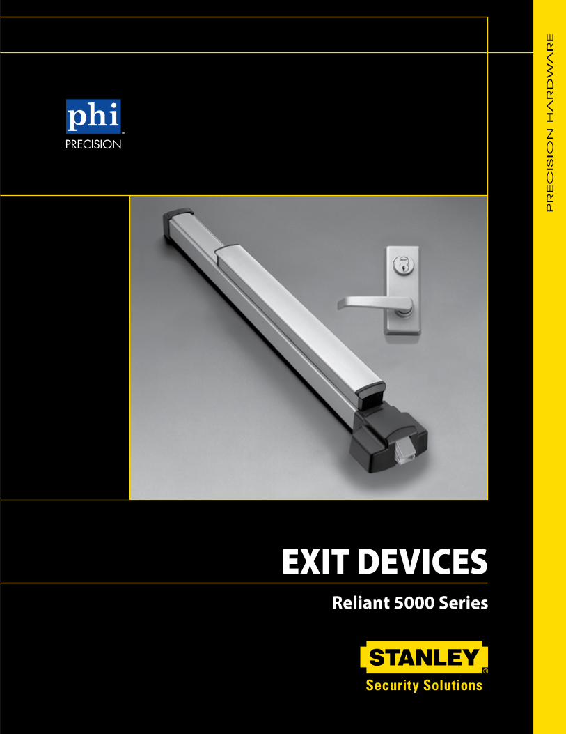
exit devices - precision...
TRANSCRIPT
PR
EC
ISIO
N H
AR
DW
AR
E
Reliant 5000 Series
EXIT DEVICES

2 R E L I A N T 5 0 0 0
TABLE OF CONTENTS
EXIT DEVICES & TRIMS Page Rim Devices ...................................................................4, 5 Surface Vertical Rod Devices ........................................6, 7
MULLIONS Fire Labeled Removable Mullion .......................................8 Key Removable Mullion .....................................................8 Removable Mullion ............................................................8
EXIT DEVICE OPTIONS ALK Exit Alarm ................................................................10 CD Cylinder Dogging .........................................................9 LD Less Dogging ...............................................................9 TDS Touchbar Monitoring Double Switch .......................10 TS Touchbar Monitoring ..................................................10 WALK Exit Alarm .............................................................10 WTDS Weatherized Touchbar Mon. Double Switch .......10 WTS Weatherized Touchbar Monitoring .........................10
ACCESSORIES Page ALK Exit Alarm Kit ...........................................................10 CDK Cylinder Dogging Kit .................................................9 Cylinders ..........................................................................11 Miscellaneous Components ...............................................9 Sex Nuts & Bolts ................................................................3 Strikes ................................................................................9
ADDITION INFORMATION Device Dimensions ............................................................3 Device Minimum Stile Width ............................................11 Fasteners ...........................................................................3 Finishes ..............................................................................3 Fire Label Rating Chart .....................................................3 Touchbar Clearance ..........................................................2 Trim Dimensions ............................................................5, 7G
EN
ER
AL IN
FO
RM
ATIO
N
INTRODUCTION
The Reliant 5000 Series is the Exit Device of choice when an economical and reliable exit device is required. All Reliant 5000 Series Exit Devices are UL listed for panic and fire hardware and are certified to ANSI A156.3 Grade 1. The Reliant Series is available in durable powder coat finishes with a variety of trim styles and functions. The chassis is constructed of stainless steel and covers the standard type 161 door preparation.
Sound Dampeners reduce the noise associated with Exit Device operation on the depression and return stroke of the Touchpad.
Quiet Operation
Touchbar Clearance
The Reliant Exit Devices accommodate doors with vision lites or glass windows, where the vision lite frames or moldings project up to 1/4” beyond the face of the door. Active Case and End Cap Mounting Bracket are mounted on the face of the door without any shims or cutting off the glass molding. These devices have a 1/4” gap between the face of the door and the Touchbar Assembly. This gap allows proper functioning of the devices even on doors which are not perfectly flat. Since the Active Case is mounted directly on the face of the door, it accommodates standard lengths of through bolting screws, lever, and cylinder tail pieces.
Exit Device
Door (Top View)
1/4” Gap

3S E R I E S D E V I C E S
1-5/8”
GEN
ER
AL IN
FO
RM
ATIO
N
GENERAL INFORMATION
Device Dimensions
FIR
E LA
BEL R
ATIN
G
Device Active Case
FinishesANSI/BHMA Description 600 Primed for Paint 689 Aluminum Paint 695 Dark Bronze Paint
FastenersFurnished standard with machine screws and full thread wood/sheet metal screws. Specify Sex Nuts and Bolts (SNB) where recommended or required by the door manufacturer.
Sex Nuts & Bolts (not furnished std.)
Sex Nuts & Bolts are furnished with No. 10-24 x 1” OHMS (1-1/2” long screws required for guides).
Door SizesStock sizes for door widths and heights are listed below. If required, cut to size in the field.
Door Widths Stock Sizes
2’-7” to 3’-0” 3’-0”3’-1” to 4’-0” 4’-0”
Vertical Rod DevicesDevice Door Heights Stock Sizes
Surface Vertical up to 7’-0” 7’-0”Rod Device* 7’-1” to 8’-0” 8’-0” 8’-1” to 10’-0” 10’-0”
Hand of Doors
Inside
Outside
LHRB Shown RHRB Shown
Active Case covers ANSI A115.2 (Type 161) or ANSI A115.18 cylinder lock preparation. Active Case through bolts in ANSI A115.18 preparation without additional machining. Specify Cover Plate or Trim to cover outside cutout.
FIRE LABEL RATING
Single Door
Type and Door Exit Device UL Fire Door RatingApplication Opening Series
Rim Device 4’-0” W x 10’-0” H FL5100 • • • • • •
(A) (B) (C) (D) (E) 20 3 1-1/2 3/4 1-1/2 3/4 min. Hour Hour Hour Hour Hour Door
Pair Of DoorsTwo Rim Devices with Mullion 8’-0” W x 8’-0” H
FL5100 xFL822, FLKR822
• • • • • •
All Fire Exit Hardware conforms to UL10C and UBC 7-2.Consult with Door Manufacturer for specific limitations on Fire Door Assemblies.
Two Surface Vertical RodDevices Swinging in theSame or Opposite Direction
8’-0” W x 10’-0” H FL5200,FL5200LBR
• • • • • •
2-3/8”
4-7/16”
2-1/2”
2-3/16”
3-1/2”TouchbarNeutral
2-5/8”Touchbar
Depressed

4 R E L I A N T 5 0 0 0
RIM
EX
IT D
EV
ICES
HO
W TO
O
RD
ER
5100
Reliant 5100 Series – Non HandedReliant FL5100 Fire Exit Series – Non Handed
RIM EXIT DEVICES
DOORS - For all types of single and double doors with a mullion. For mullions, see page 8. Available for 1-3/4” to 2-1/4” thick, up to 4’-0” wide openings. For thicker doors, consult factory. Furnished standard for 1-3/4” thick, 3’-0” wide openings.
ACTIVE CASE & TRIM - Covers ANSI A115.2 (Type 161) or ANSI A115.18 cylinder lock preparation. Active Case through bolts in ANSI A115.18 preparation without additional machining.
FUNCTIONS - Universal Exit Device, add Trim for the desired function.
ACTIVE CASE COVER & ENDCAP - High Impact Thermoplastic.
ACTIVE CASE - Stainless Steel.
TOUCHBAR SUB-ASSEMBLY - Zinc Dichromate plated Heavy Wrought Steel.
TOUCHBAR ASSEMBLY - Powder Coated Heavy Wrought Steel.
STRIKES - No. S300, Investment Cast Stainless Steel, Black Powder Coated furnished standard. No. S988, optional strike for use on Aluminum Door applications, specify when ordering. No. S458, optional strike for use on Mullion applications, specify when ordering. For optional strike information see page 9.
LATCHBOLT - Stainless Steel, Deadlocking, 3/4” throw.
DOGGING - 1/4 turn hex key dogging standard. NOT available on Fire Exit Hardware.
TOUCHBAR HEIGHT - 40-5/16” from floor standard. May be varied as situation dictates.
UL LISTED - Panic and Fire Exit Hardware. For FIRE EXIT HARDWARE Ratings see page 3. Conforms to UL10C and UBC 7-2.
ANSI/BHMA - Devices are BHMA certified for ANSI 156.3, Grade 1.
FINISHES - 689 Aluminum Powder Coat, 695 Dark Bronze Powder Coat.
CYLINDERS - See page 11.
STILE WIDTH - See Stile Information on page 11.
DEVICE OPTIONSSuffix Description Page ALK Exit Alarm: battery operated ..............................10 ALW Exit Alarm: remote power...................................10 CD Cylinder Dogging..................................................9 FL Fire Exit Hardware ............................................3,4 LD Less Dogging .......................................................9 TDS Touchbar Monitoring Double Switch ..................10 TS Touchbar Monitoring Switch ..............................10 WTDS Weatherized Touchbar Mon. Dbl. Switch ..........10 WTS Weatherized Touchbar Monitoring Switch .........10
S300Standard
S458Optional
S988Optional
Device Only: Device no., hand, finish, strike, and door size including thickness: (e.g. FL5108 x RHRB x 689 x S300 x 3’-0” x7’-0” x 1-3/4” )Trim Only: Trim no., hand, finish, and door thickness: (e.g. 808A x RHRB x 689 x 1-3/4” ) * 5103 & FL5103 Cylinder Only Application includes Cylinder Attachment Kit “CA-03”.
How To Order – 5100 Series
RHLH
RHRBLHRB
501 – cover plate602 – trim no key603 – trim w/key702A – handle no key703A – handle w/key808A – lever w/key814A – lever no key
Trim No.
689695
5108 RHRB808 689Device No. Handing Door Size
3’ 0” x 7’ 0” x 1 3/4”
S300Strike
S300 – rim/top (std.) S301 – rim/top (opt.)
S458 – rim (optional)
S459 – non fire (optional)
S460 – bottom (std.)
S988 – roller (opt.)
Finish
5101– exit only5102– dummy trim5103– key retracts latchbolt5108– key locks/ unlocks lever5114– no cylinder lever always active
ALKDevice options
See above

5S E R I E S D E V I C E S
TR
IMSTRIMS
Notes:
Trims are certified to ANSI/BHMA A156.3, Grade 1.
501Cover Plate
602Entrance by trim when touchbar is dogged down.
603Entrance by trim when latchbolt is retracted by key. Key removable only when locked.
702AEntrance by trim when touchbar is dogged down.
703AEntrance by trim when latchbolt is retracted by key. Key removable only when locked.
CYLINDERS - Not furnished standard. For Cylinder details see page 11. Rim Cylinder - Required for 603 & 703A Trim. Mortise Cylinder - Required for 808A Trim. Use 1-1/4” long standard mortise cylinder.LEVER TRIMS - (808A, 814A) are handed, but are field reversible. Specify Handing when ordering.TRIMS - are through bolted and will cover 161 cutouts.
The measurement from the Trim Horizontal Centerline to the Lever Horizontal Centerline is 1-7/16”.
2-3/4”1/8”
4”
2-3/4”1”
5-7/8”
2-3/4”2”
10”
6”
808AEntrance by lever, keylocks or unlocks lever.
814AEntrance by lever. Always active – No cylinder
6-5/8”
2-3/4”
2-13/16”
4-3/4”

6 R E L I A N T 5 0 0 0
SU
RFA
CE V
ER
TIC
AL R
OD
EX
IT D
EV
ICES SURFACE VERTICLE ROD EXIT DEVICES
S300
S460
Reliant 5200 Series – ReversibleReliant FL5200 Fire Exit Series – Reversible
DOORS - For all types of single and double door applications. Available for 1-3/4” to 2-1/4” thick, up to 4-0” wide by 10’- 0” high openings. For thicker doors, consult factory. Furnished standard for 1-3/4” thick, 3’-0” wide by 7’- 0” high openings.
ACTIVE CASE & TRIM - Covers ANSI A115.2 (Type 161) or ANSI A115.18 cylinder lock preparation. Active case through bolts in ANSI A115.18 preparation without additional machining.
FUNCTIONS - Universal Exit Device, add Trim for the desired function.
ACTIVE CASE COVER, LATCH COVERS & ENDCAP - High Impact Thermoplastic.
ACTIVE CASE & TOUCHBAR SUB-ASSEMBLY - Zinc Dichromate plated Heavy Wrought Steel.
TOUCHBAR ASSEMBLY - Powder Coated Heavy Wrought Steel.VERTICAL RODS - Powder Coated Steel.
TOUCHBAR HEIGHT - 40-5/16” from floor standard. Specify required height if other than standard.
REVERSIBLE - Reversible for all functions and trims. Standard packaging RHRB.
UL LISTED - Panic and Fire Exit Hardware. For FIRE EXIT HARDWARE Ratings see page 3. Conforms to UL10C and UBC 7-2.
ANSI/BHMA - Devices are BHMA certified for ANSI 156.3, Grade 1.
FINISHES - 689 Aluminum Powder Coat, 695 Dark Bronze Powder Coat.
STILE WIDTH - See Stile information on page 11.
CYLINDERS - See page 11.
LESS BOTTOM ROD (LBR) OPTION - Specify suffix “LBR” (e.g. 5200LBR). See UL FIRE LABEL Rating Chart on page 11. Fire Rated Devices include FB277 Fire Bolt Assembly.
BOTTOM BOLT - Steel plated, independent action 5/8” throw, with adjustment range to suit 3/4” door undercut. TOP STRIKE - No. S300, Investment Cast Stainless Steel, Black Powder Coated.
BOTTOM STRIKE - No. S460, Steel, Black Powder Coated, flush mounted.
DOGGING - 1/4 turn hex key dogging standard. Not available for Fire Exit Hardware.
TOP LATCHBOLT - Stainless Steel, Deadlocking, 3/4” throw.
Suffix Description Page ALK Exit Alarm: battery operated ..........................10 ALW Exit Alarm: remote power ..............................10 CD Cylinder Dogging ..............................................9 FL Fire Exit Hardware ........................................3,6 LBR Less Bottom Rod .............................................6 LD Less Dogging .............................................9 TDS Touchbar Monitoring Double Switch.............10 TS Touchbar Monitoring Switch ..........................10 WALW Weatherized Exit Alarm: remote ........... .......10 WTDS Weatherized Touchbar Mon. Dbl Switch ......10 WTS Weatherized Touchbar Mon. Switch ............10
DEVICE OPTIONS
Device Only: Device no., hand, finish, strike, and door size including thickness: (e.g. FL5208RALK x RHRB x 689 x S300 x 3-0 x 7-0 x 1-3/4)Trim Only: Trim no., hand, finish, and door thickness: (e.g. 808A RHRB 689 1-3/4) * 5203 & FL5203 Cylinder Only Application includes Cylinder Attachment Kit “CA-03”.
How To Order – 5200 Series
RHLH
RHRBLHRB
501 – cover plate602 – trim no key603 – trim w/key702A – handle no key703A – handle w/key808A – lever w/key814A – lever no key
Trim No.
689690691693695696
5208 ALK RHRB808 689Device No. Device
optionsHanding Door Size
3’ 0” x 7’ 0” x 1 3/4”
S300Strike
S300 – rim/top (std.) S301 – rim/top (opt.)
S458 – rim (opt.)
S459 – non fire (opt.)
S460 – bottom (std.)
S988 – roller (opt.)
Finish
5201– exit only5202– dummy trim5203– key retracts latchbolt5208– key locks/ unlocks lever5214– no cylinder lever always active
See above

7S E R I E S D E V I C E S
TR
IMSTRIMS
Notes:
Trims are certified to ANSI/BHMA A156.3, Grade 1.
501Cover Plate
602Entrance by trim when touchbar is dogged down.
603Entrance by trim when latchbolt is retracted by key. Key removable only when locked.
702AEntrance by trim when touchbar is dogged down.
703AEntrance by trim when latchbolt is retracted by key. Key removable only when locked.
CYLINDERS - Not furnished standard. For Cylinder details see page 11. Rim Cylinder - Required for 603 & 703A Trim. Mortise Cylinder - Required for 808A Trim. Use 1-1/4” long standard mortise cylinder.LEVER TRIMS - (808A, 814A) are handed, but are field reversible. Specify Handing when ordering.TRIMS - are through bolted and will cover 161 cutouts.
2-3/4”1/8”
4”
2-3/4”1”
5-7/8”
2-3/4”2”
10”
6”
808AEntrance by lever, keylocks or unlocks lever.
814AEntrance by lever. Always active – No cylinder
6-5/8”
2-3/4”
2-13/16”
4-3/4”

8 R E L I A N T 5 0 0 0
MU
LLIO
NS MULLIONS
Removable Mullions The Mullion is used to adapt a double door opening to two single door openings with Rim Exit Devices. When the full width of an opening is required, the mullion may be removed.
Key Removable Mullion (KR) – Provides a secure yet quick & easy means of removing the 822 or FL822 Mullion. The mullion can be reinstalled and locked without the need of the key.
Stock Size– For openings 8’-0” high. For openings less than 8’-0” high the mullion can be cut down. For openings greater than 8’-0” high using the 822, KR822 or 811 mullions, consult factory.
Finishes – 600, 689, 695. For Finish description see page 3.
822, FL822, KR822, FLKR822 MullionU.L. Listed – FL822 and FLKR822 listed for Fire Exit Hardware. For FIRE LABEL RATING Chart see page 11.
Mullion – 2” x 3” Steel.
Mullion Base – Investment Cast Steel, 2” wide 3-1/2” deep. Furnished with steel anchors for concrete floors.
Interlock - Black Powder Coated Investment Cast Stainless Steel. Furnished standard for FL822 and FLKR822 Mullions. It interlocks the mullion to the Rim Active Case and S300 or S301 Strike.
Stabilizers – Black Powder Coated Steel. Stabilizers are furnished standard for FL822 and FLKR822 Mullions.
Mullion Cap Spacer – Minimum width 3-1/2”. For 2-1/4” frame spacer specify part no. MCS822.
822, FL822 Mullion Cap - MC822 Investment Cast Steel, 4 wide 3-5/8 deep.
KR822, FLKR822 KEY Removable Mullion Cap Assembly - Investment Cast Steel - can be ordered to convert existing 822 or FL822 mullions to Keyed Removable Mullions. Retrofits to the hole pattern of an MC822 Mullion Cap. To order specify KMC822 or KMC822F. For wire run information, please consult factory.
Cylinder – Not furnished standard - Rim Type required. See page 11 for cylinder details.
MullionCapMC822
MullionBaseMB822
MullionCapMC811
MullionBaseMB811
Key RemovableMullion CapKMC822(Rim Cylinder required)
Mullion Cap SpacerMCS822
InterlockS1447
StabilizerST989
HC822, HCKR822 Mullion
MULLION – 2” x 2” Steel Mullion.
MULLION CAP – Cast 4-1/2” wide x 2-5/16”, furnished with machine screws for metal frames.
MULLION BASE – Cast 2” wide x 2-3/4”, furnished with sheet metal screws and plastic anchors.
811 Mullion
To Order: Specify Mullion No. x Height x Finish (e.g. 822 x 8’-0” x 600)
9S E R I E S D E V I C E S
AC
CESSO
RIE
SACCESSORIES
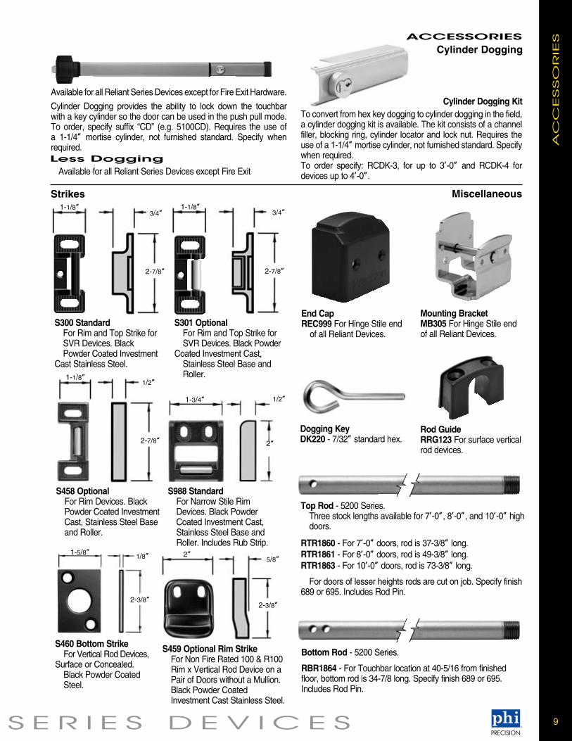
Strikes
1-1/8”1/2”
2-7/8”
1-3/4” 1/2”
2”
S458 Optional For Rim Devices. Black Powder Coated Investment Cast, Stainless Steel Base and Roller.
S988 Standard For Narrow Stile Rim Devices. Black Powder Coated Investment Cast, Stainless Steel Base and Roller. Includes Rub Strip.
S300 Standard For Rim and Top Strike for SVR Devices. Black Powder Coated Investment Cast Stainless Steel.
Available for all Reliant Series Devices except for Fire Exit Hardware.
Cylinder Dogging provides the ability to lock down the touchbar with a key cylinder so the door can be used in the push pull mode. To order, specify suffix “CD” (e.g. 5100CD). Requires the use of a 1-1/4” mortise cylinder, not furnished standard. Specify when required.
1-1/8”3/4”
2-7/8”
1-1/8”3/4”
2-7/8”
S301 Optional For Rim and Top Strike for SVR Devices. Black Powder Coated Investment Cast, Stainless Steel Base and Roller.
S460 Bottom Strike For Vertical Rod Devices, Surface or Concealed. Black Powder Coated Steel.
1-5/8”1/8”
2-3/8”
S459 Optional Rim Strike For Non Fire Rated 100 & R100 Rim x Vertical Rod Device on a Pair of Doors without a Mullion. Black Powder Coated Investment Cast Stainless Steel.
2”5/8”
2-3/8”
Miscellaneous
Dogging KeyDK220 - 7/32” standard hex.
Top Rod - 5200 Series. Three stock lengths available for 7’-0”, 8’-0”, and 10’-0” high doors.
RTR1860 - For 7’-0” doors, rod is 37-3/8” long.RTR1861 - For 8’-0” doors, rod is 49-3/8” long.RTR1863 - For 10’-0” doors, rod is 73-3/8” long.
For doors of lesser heights rods are cut on job. Specify finish 689 or 695. Includes Rod Pin.
Bottom Rod - 5200 Series.
RBR1864 - For Touchbar location at 40-5/16 from finished floor, bottom rod is 34-7/8 long. Specify finish 689 or 695. Includes Rod Pin.
Rod GuideRRG123 For surface vertical rod devices.
End CapREC999 For Hinge Stile end of all Reliant Devices.
Mounting BracketMB305 For Hinge Stile end of all Reliant Devices.
To convert from hex key dogging to cylinder dogging in the field, a cylinder dogging kit is available. The kit consists of a channel filler, blocking ring, cylinder locator and lock nut. Requires the use of a 1-1/4” mortise cylinder, not furnished standard. Specify when required.To order specify: RCDK-3, for up to 3’-0” and RCDK-4 for devices up to 4’-0”.
Cylinder Dogging Kit
Cylinder Dogging
Less Dogging Available for all Reliant Series Devices except Fire Exit

10 R E L I A N T 5 0 0 0
EX
IT A
LA
RM
EXIT ALARM
RALK - Battery Operated, provided with a 9 Volt battery and has an audible low battery indicator. Specify WH495 Wire harness for Remote Arm/Disarm or alternate input Activation options. RALW - Remote Powered 12 to 24 VDC at 0.25 Amp., a (2) wire power transfer hinge is required (furnished by others). Specify WH495 Wire harness for Remote Arm/Disarm or alternate input Activation options. The Exit Alarm provides a simple way to audibly monitor the use of an exit device. The unit contains a Piezo Alarm which will sound when the touchbar is depressed. Alarm sounds at 80db at 10 feet.It is also equipped with an LED indicator. The LED flashes GREEN for 20 seconds when the unit is arming and flashes RED every 20 seconds when the unit is armed.Note: Touchbar Monitoring Switch (TS) is recommended when using Alarm option with 5200 Series Surface Vertical Rod devices.
CylinderThe ALK and ALW requires a standard 1-1/4” Mortise Cylinder which is used as a key switch to perform the following functions: • To turn on (Arm) - it will allow 20 seconds to exit before alarm sounds. • Silence and reset the alarm after unauthorized egress. • To turn off (Disarm) the alarm for continuous unmonitored egress. • Engage mechanical Dogging for Non-Fire Rated Devices.Available for all Reliant Devices from 3’-0” to 4’-0” wide doors. Furnished with Touchbar decal which states:
Wiring Harness - WH495Can be wired for one or both of the options listed below. • Exit Alarm can be turned on (Armed) with alternate inputs. For other than our Door Position Switch a (2) wire power transfer hinge is required (furnished by others). • Exit alarm can be turned on (Armed) or off (Disarmed) from a remote location. A Mortise Cylinder or Dummy Cylinder is required. A (2) wire power transfer hinge is required (furnished by others).To Order: specify WH495.To Order: Device with Alarm - add suffix “ALK”, “ALW” (e.g. 5100ALK)
Available for all Reliant Series Devices. The Weatherized Exit Alarm is identical in operation to the standard Exit Alarm but incorporates a weatherized design for use on a variety of applications where contact with the elements may occur.
WALW - Remote Powered 12 to 24 VDC at 0.25 Amp., a (2) wir power transfer is required, not furnished standard. Specify WH495 Wire Harness for Remote Arm/Disarm or alternate Input Activation options. Weather resistant loss prevention hardware designed for use in outdoor or wet environments • Meets the requirements of MIL-STD 810F, Method 506.4, Driving Rain Test (simulating 4 in./hr. rain with 40 mph wind) • Meets the requirements of MIL-STD 810F, Method 509.4, Salt Fog test (simulating effects of corrosive environments similar to atmospheric conditions found in costal regions)
To Order: Device with Weatherized Exit Alarm - add suffix “WALW” to Device No. (e.g. 5208WALW)
!!EMERGENCY EXIT ONLY!! PUSH TO OPEN ALARM WILL SOUND
Weatherized Exit Alarm
Available for all Reliant Series Devices. The Touchbar Monitoring Switch is an internally mounted switch that is used to signal electromagnetic locks, horns, monitoring stations or other electronic components. • UL Listed for Panic and Fire for Class II Circuitry. • TS and TDS can be used in combination with all options.TS (SPDT - Single Pole, Double Throw) version allows for interface with one external component. A (2) wire power transfer is required, not furnished standard. TDS (DPDT - Double Pole, Double Throw) version allows for interface with two external components. A (4) wire power transfer is required, not furnished standard.
To Order: specify prefix TS or TDS (e.g. TS5108)
Electrical Ratings: TS: Switch rated to 2 Amps at 24VDC SPDT TDS: Switch rated to 2 Amps at 24VDC DPDT
Touchbar Monitoring
Available for all Reliant Series Devices. Weatherized Touchbar Switch WTS/WTDS is designed for use on a variety of exit device applications where contact with the elements may occur. Provided with identical functions as the standard Touchbar monitoring. • Meets the requirements of MIL-STD 810F, Method 506.4, Driving Rain Test (simulating 4 in./hr. rain with 40 mph wind) • Meets the requirements of MIL-STD 810F, Method 509.4, Salt Fog test (simulating effects of corrosive environments similar to atmospheric conditions found in costal regions)
To Order: specify prefix WTS or WTDS (e.g. WTS5108)
Weatherized Touchbar Monitoring
The Exit Alarm is available in kits for retrofit on existing devices. Specify finish when ordering, see page 3.
3’-0” RALK-3, RALW-3 4’-0” RALK-4, RALW-4 • WH495 Wiring Harness - Required for Remote Arming/ Disarming the Alarm. • Reliant Series, kits are available in 689 or 695 Finishes. • To order specify Kit No. and Finish (e.g. ALK-3 689). * For Battery operated kits a 9 Volt Battery is included.
Exit Alarm Kits
11S E R I E S D E V I C E S
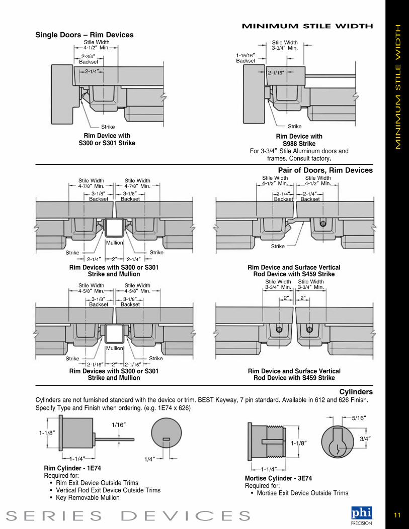
MINIMUM STILE WIDTHSingle Doors – Rim Devices
Pair of Doors, Rim Devices
2-3/4”Backset
2-1/4”
Stile Width 4-1/2” Min.
Strike
Rim Device withS300 or S301 Strike
1-15/16”Backset
2-1/16”
Stile Width 3-3/4” Min.
Strike
Rim Device withS988 Strike
For 3-3/4” Stile Aluminum doors and frames. Consult factory.
2-1/4” 2”Strike
Mullion
Rim Devices with S300 or S301Strike and Mullion
CylindersM
INIM
UM
STIL
E W
IDTH
3-1/8”Backset
Stile Width 4-7/8” Min.
2-1/4”Strike
Stile Width 4-7/8” Min.3-1/8”
Backset
Strike
2-1/4”Backset
Stile Width 4-1/2” Min.
Stile Width 4-1/2” Min.
2-1/4”Backset
Rim Device and Surface VerticalRod Device with S459 Strike
2-1/16” 2”Strike
Mullion
Rim Devices with S300 or S301Strike and Mullion
3-1/8”Backset
Stile Width 4-5/8” Min.
2-1/16”Strike
Stile Width 4-5/8” Min.
3-1/8”Backset
2”
Stile Width 3-3/4” Min.
2”
Stile Width 3-3/4” Min.
Rim Device and Surface VerticalRod Device with S459 Strike
Cylinders are not furnished standard with the device or trim. BEST Keyway, 7 pin standard. Available in 612 and 626 Finish. Specify Type and Finish when ordering. (e.g. 1E74 x 626)
1-1/8”
1-1/4”
1/16”
1/4”Rim Cylinder - 1E74Required for: • Rim Exit Device Outside Trims • Vertical Rod Exit Device Outside Trims • Key Removable Mullion
1-1/8”
1-1/4”
5/16”
3/4”
Mortise Cylinder - 3E74Required for: • Mortise Exit Device Outside Trims

10M 1109FPPHI006
STANLEYsecuritysolutions.com
Stanley Security Solutions, a business division of Stanley Black & Decker, is a provider of integrated access control and security solutions for institutional, commercial and industrial businesses and organizations. Stanley Security Solutions delivers a comprehensive suite of security products, software and integrated systems with a strong emphasis on service. Stanley Security Solutions is committed to extending its position as a leading comprehensive resource for a broad and extensive array of solutions that span the entire security spectrum.
PHI-006 • 11/14© 2014 Stanley Security Solutions, Inc.
PR
EC
ISIO
N H
AR
DW
AR
E