european xfel phase shifter: pc-based control system · european xfel phase shifter: pc-based...
TRANSCRIPT
EUROPEAN XFEL PHASE SHIFTER: PC-BASED CONTROL SYSTEM
E. Molina Marinas∗, J.M. Cela-Ruiz, J. de la Gama, A. Guirao, L.M. Martinez Fresno, I. Moya,A.L. Pardillo, S. Sanz, C. Vazquez, CIEMAT, Madrid, Spain
Abstract
The Accelerator Technology Unit at CIEMAT is incharge of part of the Spanish contribution to the Euro-pean X-Ray Free-Electron Laser (EXFEL) [1]. This pa-per presents the control system of the Phase Shifter (PS),a beam phase corrector magnet that will be installed in theintersections of the SASE undulator system. Beckhoff hasbeen chosen by EXFEL as its main supplier for the indus-trial control systems. Beckhoff Twincat PLC architectureis a PC-based control technology built over EtherCAT, areal-time Ethernet fieldbus. The PS is operated with a step-per motor, its position is monitored by an incremental en-coder, and it is controlled by a Twincat-PLC program us-ing the TcMC2 library, an implementation of the PLCopenMotion Control specification. A GUI has been developedin LabVIEW instead of using Beckhoff visualization tool.The control system for the first and second prototype de-vices has been developed in-house using COTS hardwareand software. The specifications request a repeatability of(±50µm) in bidirectional movements and (±10µm) in uni-directional movements. The second prototype can reachspeeds up to 15 mm/s.
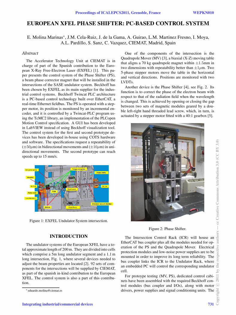
Figure 1: EXFEL Undulator System intersection.
INTRODUCTION
The undulator systems of the European XFEL have a to-tal approximate length of 200 m. They are divided into cellswhich comprise a 5m long undulator segment and a 1.1 mlong intersection, Fig. 1, where several devices needed toadjust the beam properties are located [2]. 92 sets of com-ponents for the intersections will be supplied by CIEMAT,as part of the spanish in-kind contribution to the EuropeanXFEL. The control system is also a part of this contribu-tion.
One of the components of the intersection is theQuadrupole Mover (MV) [3], a biaxial (X-Z) moving tablethat aligns a 70 kg quadrupole magnet within ±1.5mm intwo dimensions with repeatability better than ±1µm. Two5-phase stepper motors move the table in the horizontaland vertical directions. Positions are monitored with twoLVDTs.
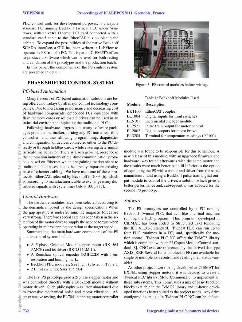
Another device is the Phase Shifter [4], see Fig. 2. Itsfunction is to correct the phase of the electron beam withrespect to that of the radiation field when the wavelengthis changed. This is achieved by opening or closing the gapbetween two sets of magnetic modules geared by a dou-ble left-right hand threaded lead screw, which, in turn, isactuated by a stepper motor fitted with a 40:1 gearbox [5].
Figure 2: Phase Shifter.
The Intersection Control Rack (ICR) will house anEtherCAT bus coupler plus all the modules needed for op-eration of the PS and the Quadrupole Mover. Electricalprotection modules and low-noise power supplies are to bemounted in order to improve its long term reliability. Thebus coupler links the ICR to the Undulator Rack, wherean embedded PC will control the corresponding undulatorcell.
For protoype testing (MV, PS), dedicated control cabi-nets have been assembled with the required Beckhoff con-trol modules (bus coupler and I/Os), along with motordrivers, power supplies and signal conditioning units. The
Proceedings of ICALEPCS2011, Grenoble, France WEPKN010
Integrating industrial/commercial devices 731 Cop
yrig
htc ○
2011
byth
ere
spec
tive
auth
ors—
ccC
reat
ive
Com
mon
sAtt
ribu
tion
3.0
(CC
BY
3.0)
PLC control unit, for development purposes, is always astandard PC running Beckhoff Twincat PLC under Win-dows, with an extra Ethernet PCI card connected with astandard cat-5 cable to the EtherCAT bus coupler in thecabinet. To expand the possibilities of the native BeckhoffSCADA interface, a GUI has been written in LabView tooperate the PS from the PC. This is part of CIEMAT’s effortto produce a software which can be used for both testingand validation of the prototypes and the production batch.
In this paper, the components of the PS control systemare presented in detail.
PHASE SHIFTER CONTROL SYSTEM
PC-based Automation
Many flavours of PC-based automation solutions are be-ing offered nowadays by all major control technology com-panies. Due to increasing performance and decreasing costof hardware components, embedded PCs equipped withflash memory cards or solid-state drives can be used in anindustrial environment replacing the traditional PLCs.
Following hardware progression, many software pack-ages populate the market, turning any PC into a real-timecontroller, and thus allowing programming, diagnosticsand configuration of devices connected either to the PC di-rectly or through fieldbus cards, while ensuring determinis-tic real-time behavior. There is also a growing presence inthe automation industry of real-time communication proto-cols based on Ethernet which are gaining market share totraditional field buses due to the already important existingbase of ethernet cabling. We have used one of these pro-tocols, EtherCAT, released by Beckhoff in 2003 [6], whichis, according to manufacturers, able to exchange many dis-tributed signals with cycle times below 100 µs [7].
Control HardwareThe hardware modules have been selected according to
the demands imposed by the design specifications Whenthe gap aperture is under 20 mm, the magnetic forces arevery strong. Therefore special care has been taken in the se-lection of the motor drive to supply the needed torque whenoperating in microstepping operation at the target speed.
Summarising, the main hardware components of the PSand its control system include:
• A 5-phase Oriental Motor stepper motor (RK 564AMCE) and its driver (RKD514LM-C).
• A Renishaw optical encoder (RGH22D) with 1µmresolution and homing mark.
• Beckhoff PLC modules, (see Fig. 3) , listed in Table 1.• 2 Limit switches, Saia T85 5E4
The first PS prototype used a 2-phase stepper motor andwas controlled directly with a Beckhoff module withoutmotor driver. Such philosophy was later abandoned dueto excessive mechanical noise and motor vibration. Af-ter extensive testing, the EL7041 stepping motor controller
Figure 3: PS control modules before wiring.
Table 1: Beckhoff Modules Used
Module Description
EK1100 EtherCAT couplerEL1004 Digital inputs for limit switchesEL5101 Incremental encoder moduleEL2521 Pulse train output for motor controlEL2002 Digital outputs for motor brakeEL3204 Terminal for temperature readings (PT100)
module was found to be responsible for this behaviour. Anew release of this module, with an upgraded firmware andhardware, was tested afterwards with the same motor andthe results were much better but still inferior to the optionof equipping the PS with a motor and driver from the samemanufacturer and using a Beckhoff pulse train digital out-put module to control the driver, a solution which gives abetter performance and, subsequently, was adopted for thesecond PS prototype.
Software
The PS prototypes are controlled by a PC runningBeckhoff Twincat PLC, that acts like a virtual machinerunning the PLC program. This program, developed atCIEMAT, has been coded in Structured Text followingthe IEC 61131-3 standard. Twincat PLC can run up tofour PLC runtimes in a PC, and, specifically for mo-tion control, Twincat PLC NC offers the TcMC2 librarywhich is compliant with the PLCopen Motion Control stan-dard [8]. CNC axes are referenced by the derived datatypeAXIS_REF. Several function blocks (FB) are available forsingle or multiple axis control and reading their status vari-ables.
As other projects were being developed at CIEMAT forEXFEL using stepper motors, it was decided to create aTwincat PLC library, MotorCommon.lib, to implement allthese subsystems. This library uses a mix of basic functionblocks available in the TcMC2 library and in-house devel-oped functions better suited to the project needs. Any driveconfigured as an axis in Twincat PLC NC can be defined
WEPKN010 Proceedings of ICALEPCS2011, Grenoble, France
732Cop
yrig
htc ○
2011
byth
ere
spec
tive
auth
ors—
ccC
reat
ive
Com
mon
sAtt
ribu
tion
3.0
(CC
BY
3.0)
Integrating industrial/commercial devices
as an instance of the MotorControlWTimedBrakeAutoPowfunction block. A wrapper (i.e. MoverMotor or Phase-ShifterMotor) adapts the FB to any motor characteristics.For example, the PS stepper motor comes equipped withan electromagnetic brake and the motor windings can beactivated or deactivated following an on/off signal. Dueto the incremental nature of the position feedback, the PSwrapper defines also a homing procedure that has to be car-ried out when the device is started up or after an error. Ev-ery motor operational parameter, such as brake delay time,deadband position, backslash compensation, timeout andmaximum operating temperature can also be configured.
Figure 4: Axis configuration in Twincat System Manager.
The Twincat System Manager (see Fig. 4) is the configu-ration tool for the EtherCAT system, the PLC program, theI/O modules and the mechanical axes. A motor, or moregenerically a drive, can be defined as a Computer Numeri-cal Control (CNC) axis and then linked to the correspond-ing modules. An axis has two basic elements, plus a thirdone: i) the actuator or drive, ii) the encoder or feedback,and iii) the controller or control policy. For instance, thePS axis is linked to both a pulse train output card (EL2521)and an incremental encoder card (EL5101). The controllercan also be chosen and configured. The PS uses a positionP control plus velocity PID with torque. The parametersfor this controller have been manually tuned.
Although Twincat PLC comes with its own visualizationtool, a classical SCADA GUI package, LabVIEW GUIs(see Fig. 5) have been developed in-house to take advantageof LabVIEW flexibility. The communication between Lab-VIEW and Twincat PLC has been achieved by using theBeckhoff TcADSdll.Dll library, which organises data ex-change between Windows programs and Twincat. On topof that, a series of functions have been created to controlthe PLC from our GUI: start or stop the PLC, read vari-ables and send data and commands. However this com-munication is asynchronous to the PLC cycle, forcing theLabview programm to constantly interrogate the TwinCATserver for changes in the status of signals. This could bea drawback for operation but does not pose any problemfor testing and measurement. The validation of the seriesproduction will also be done automatically by a LabVIEW
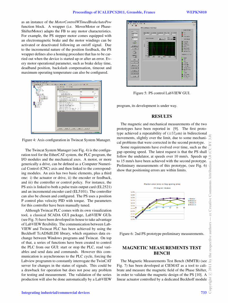
Figure 5: PS control LabVIEW GUI.
program, its development is under way.
RESULTS
The magnetic and mechanical measurements of the twoprototypes have been reported in [9]. The first proto-type achieved a repeatability of (±57µm) in bidirectionalmovements, slightly over the limit, due to some mechani-cal problems that were corrected in the second prototype.
Some requirements have evolved over time, such as thegap opening speed. The latest request is that the PS shallfollow the undulator, at speeds over 10 mm/s. Speeds upto 15 mm/s have been achieved with the second prototype.Preliminary measurements of this prototype, (see Fig. 6)show that positioning errors are within limits.
Figure 6: 2nd PS prototype preliminary measurements.
MAGNETIC MEASUREMENTS TESTBENCH
The Magnetic Measurements Test Bench (MMTB) (seeFig. 7) has been developed at CIEMAT as a tool to cali-brate and measure the magnetic field of the Phase Shifter,in order to validate the magnetic design of the PS [10]. Alinear actuator controlled by a dedicated Beckhoff module
Proceedings of ICALEPCS2011, Grenoble, France WEPKN010
Integrating industrial/commercial devices 733 Cop
yrig
htc ○
2011
byth
ere
spec
tive
auth
ors—
ccC
reat
ive
Com
mon
sAtt
ribu
tion
3.0
(CC
BY
3.0)

moves a coil inside the PS gap. This coil is connected toa fluxmeter which integrates the magnetic flux, that is thenread by a 24-bit ADC module to construct the
−→B field in-
tegral after post-processing. The PLC controls both axes(PS and MMTB) and records position, speed and magneticfield values for further analysis. The position is monitoredby an incremental rotational encoder. Its control softwarebeen written using the same libraries (PLC and LabVIEW)than the PS. Special care has been taken to synchronize thevalues that are written to a file by the PLC. Initially, af-ter data analysis, a delay of a few milliseconds was found,dependent of the speed, so that in the Field Integral ver-sus Position graph, the "in" cycle (when the coil is movedinside the PS) and the "out" cycle did not match. This isprobably caused by the way the PLC works, as it reads thevariables first and produces the timestamp at the momentof writing to the file.
Figure 7: Phase Shifter and MMTB.
CONCLUSIONS
The Accelerator Technology Unit at CIEMAT is incharge of the design, manufacturing and delivery of sev-eral components to be installed in the 92 intersections ofthe Undulators System of the European XFEL, in particu-lar, the Phase Shifter, the Quadrupole Mover and the Inter-section Control Rack. All the control hardware has beenimplemented using commercial devices. In addition wehave written a Beckhoff Twincat PLC library to encapsu-late all devices as CNC axes within the Beckhoff architec-ture. GUIs have been created, based on an in-house de-veloped LabVIEW library, able to communicate with thePLC runtime. As soon as the different prototypes have beenavailable for testing in our labs, the integration of the con-trol system has been quickly achieved. A fully automaticmeasurement procedure have been implemented. The firstprototype achieved a repeatability of (±57µm), over thelimit. The second prototype is now being tuned and thepreliminary measurements have been satisfactory.
ACKNOWLEDGEMENTS
This work is supported by the CIEMAT and the SpanishMinistry of Science and Innovation under SEI Resolutionof September 17th, 2009. The authors would like to ex-press their gratitude to our colleagues at E-XFEL, mainlyJ. Pflüger and S. Karabekyan, for their encouragement andsupport during this project.
REFERENCES
[1] The European X-Ray Free Electron Laser (E-XFEL), http://www.xfel.eu.
[2] J. Pflüger, “Undulator Systems and Photon Diagnostics forthe European XFEL Project”, FEL 2005 Stanford, Au-gust 2005, TUOC002, p.378-382, http://jacow.org/f05/PAPERS/TUOC002.PDF.
[3] J.Munilla et al., “Design, Manufacturing and Tests ofClosed-loop Quadrupole Mover Prototypes for EuropeanXFEL”. Proceedings of the 2nd International Particle Accel-erator Conference (IPAC), San Sebastian (Spain), Septem-ber 2011
[4] H.H. Lu, et al., “The permanent magnet phase shifter forthe European X-ray free electron laser”, Nuclear Instrumen-tation and Methods, part A (2009), doi:10.1016j.nima.
2009.03.217
[5] S.Sanz et al., “Evaluation of magnetic forces in permanentmagnets”. IEEE Transactions on Applied Superconductiv-ity, vol 2010, doi:10.1109/TASC.2009.2038933
[6] D.Jansen, H.Buttner “Real-Time Ethernet: the EtherCATsolution”. IET Computing Control Engineering, Feb 2004vol.15 issue 1http://www.iee.org/computingmagazine
[7] Technical Introduction and Overview, July 2005. EtherCATTechnology Group http://www.ethercat.org.
[8] PLCopen http://www.plcopen.org/.
[9] I. Moya et al., “Fabrication and testing of the first phaseshifter prototypes built by CIEMAT for the EuropeanXFEL”. Proceedings of the 2nd International Particle Accel-erator Conference (IPAC), San Sebastian (Spain), Septem-ber 2011
[10] S. Sanz et al., “Development of a Test Bench for the Mag-netic Measurements on the Phase Shifters for the EuropeanXFEL”, 22nd International Conference on Magnet Technol-ogy, Marseille (France), 2011
WEPKN010 Proceedings of ICALEPCS2011, Grenoble, France
734Cop
yrig
htc ○
2011
byth
ere
spec
tive
auth
ors—
ccC
reat
ive
Com
mon
sAtt
ribu
tion
3.0
(CC
BY
3.0)
Integrating industrial/commercial devices