etzgar conveyor · pdf fileetzgar conveyor company bdlr conveyor section –v12.05 ......
TRANSCRIPT

ETZGAR CONVEYOR COMPANY BDLR Conveyor Section –v12.05
4-1 © Metzgar Conveyor Co. 2012
Section 4 – Belt Driven Live Roller Conveyor Page Description 4-1 BDLR Conveyor Index 4-2 Steps to Assembling a Complete BDLR Conveyor 4-3 Elevation Examples 4-4 Power Conveyor Data Sheet 4-5 401 Belt Conveyor Specifications and Unit Model Number 4-6 430 Belt Conveyor Specifications and Unit Model Number 4-7 401 and 430 Bed Selection 4-8 Belt Lengths and 430 Accumulation Operation 4-9 401 Horsepower Selection 4-10 430 Horsepower Selection 4-11 401 and 430 Drive Size and Model Number 4-12 401 and 430 Drive Dimensions and End Pulley Assembly 4-13 401 and 430 Horizontal and Vertical Take-ups 4-14 435 Electronic Accumulating BDLR Elevation and Features 4-15 435 Belt Driven Conveyor Specifications and Unit Model Number 4-16 450 Series Tapered Roller Curves 4-17 450 Series Curve Tangents 4-18 450 Series 90° Spur/Merge 4-19 450 Series 45° Spur/Merge 4-20 460 Belt Conveyor Specifications and Unit Model Number 4-21 460 Bed Selection, Belt Length and End Pulley 4-22 Drive Horsepower vs. Load Chart 3” Roller Centers 4-23 Drive Horsepower vs. Load Chart 6” Roller Centers 4-24 460 Drive Model Number 4-25 Belt Driven Live Roller Conveyor Options 4-26 BDLR Replacement Parts 4-27 BDLR Replacement Parts Continued 4-28 BDLR Replacement Parts Continued
ETZGAR CONVEYOR COMPANY BDLR Conveyor Section –v12.05
4-2 © Metzgar Conveyor Co. 2012
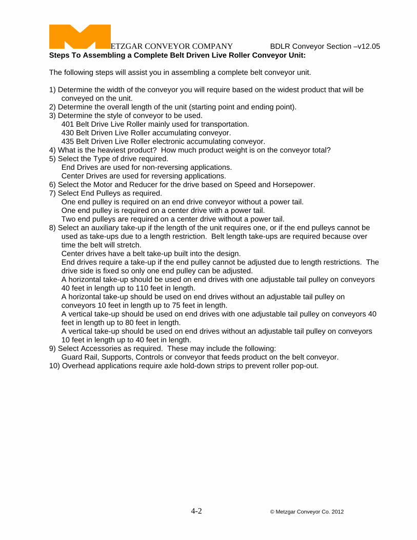
Steps To Assembling a Complete Belt Driven Live Roller Conveyor Unit: The following steps will assist you in assembling a complete belt conveyor unit. 1) Determine the width of the conveyor you will require based on the widest product that will be
conveyed on the unit. 2) Determine the overall length of the unit (starting point and ending point). 3) Determine the style of conveyor to be used. 401 Belt Drive Live Roller mainly used for transportation. 430 Belt Driven Live Roller accumulating conveyor. 435 Belt Driven Live Roller electronic accumulating conveyor. 4) What is the heaviest product? How much product weight is on the conveyor total? 5) Select the Type of drive required. End Drives are used for non-reversing applications. Center Drives are used for reversing applications. 6) Select the Motor and Reducer for the drive based on Speed and Horsepower. 7) Select End Pulleys as required.
One end pulley is required on an end drive conveyor without a power tail. One end pulley is required on a center drive with a power tail. Two end pulleys are required on a center drive without a power tail. 8) Select an auxiliary take-up if the length of the unit requires one, or if the end pulleys cannot be
used as take-ups due to a length restriction. Belt length take-ups are required because over time the belt will stretch.
Center drives have a belt take-up built into the design. End drives require a take-up if the end pulley cannot be adjusted due to length restrictions. The
drive side is fixed so only one end pulley can be adjusted. A horizontal take-up should be used on end drives with one adjustable tail pulley on conveyors
40 feet in length up to 110 feet in length. A horizontal take-up should be used on end drives without an adjustable tail pulley on conveyors 10 feet in length up to 75 feet in length. A vertical take-up should be used on end drives with one adjustable tail pulley on conveyors 40 feet in length up to 80 feet in length. A vertical take-up should be used on end drives without an adjustable tail pulley on conveyors 10 feet in length up to 40 feet in length.
9) Select Accessories as required. These may include the following: Guard Rail, Supports, Controls or conveyor that feeds product on the belt conveyor.
10) Overhead applications require axle hold-down strips to prevent roller pop-out.

ETZGAR CONVEYOR COMPANY BDLR Conveyor Section –v12.05
4-3 © Metzgar Conveyor Co. 2012
401/430 Belt Drive Live Roller Elevation Examples:

ETZGAR CONVEYOR COMPANY BDLR Conveyor Section –v12.05
4-4 © Metzgar Conveyor Co. 2012
Belt Conveyor Power Conveyor Data Sheet: Unit Model Number: Overall Unit Length: Speed of Unit: Component Part Number Description Drive
Motor Horsepower
Speed of Unit (FPM)
Bed Construction
Bottom Pans
Feeders
End Assembly
Take-ups
Connectors
Belt type and length
Accessories
Guard Rails
Trussing
Controls
Supports
Finish Metzgar Blue

ETZGAR CONVEYOR COMPANY BDLR Conveyor Section –v12.05
4-5 © Metzgar Conveyor Co. 2012
401 Belt Driven Live Roller Conveyor Specifications and Unit Model Number:
“A” Bed
Width
“B” Between
Frame
“C” Roller Width
Belt Width
12” 9 ½” 9 ¼” 6” 15” 12 ½” 12 ¼” 6” 18” 15 ½” 15 ¼” 6” 24” 21 ½” 21 ¼” 6” 30” 27 ½” 27 ¼” 12” 36” 33 ½” 33 ¼” 12” 42” 39 ½” 39 ¼” 12” 48” 45 ½” 45 ¼” 12”
Belt: 6” or 12” wide PVC Cover One Side x Slider Back with Cover Up. Frame: 10 gage x 6” deep formed steel channel with 1 ¼”” flange. Frames are welded together using 1 ½” x 1 ½” x 3/16” structural steel crossmembers. Carrier Rollers: Rollers are 1.9” diameter x 16 gage steel with ball bearings and 7/16”
hex axles. Axles are spring loaded for easy assembly or removal. Carrier rollers are available on 2.4”, 3”, 4”or 6” Centers.
Drive Pulleys: Standard Drive pulleys are 6” or 9” diameter crowned and lagged. Drive pulley shafts are1 3/16” dia, or 1 7/16” dia. End Pulleys and Take-up Pulleys: 4” diameter crowned with 1 3/16: dia. shaft.
Internal mounted bearings are standard. Drive Snubber Roller: Rollers are 2 ½” diameter 11 gage steel with ball bearings and
11/16” hex tube spanner and 7/16” diameter shaft. Belt return Idler Rollers: Rollers are 1.9” diameter x 16 gage steel with ball bearings and 7/16”
hex axles. Axles are spring loaded for easy assembly or removal. Belt Speed: 60 Feet Per Minute (FPM) is the most common. Other speeds and variable speed are available as options. 401 Belt Driven Conveyor Model Number: 401 – C - 18 - 3 - 25 - ¾
Conveyor Series Drive Type E= End C=Center Frame Bed Width Carrier Roller Centers(2.4”,3”,4”or6”) Overall Unit Length in Feet-Inches Motor Horsepower

ETZGAR CONVEYOR COMPANY BDLR Conveyor Section –v12.05
4-6 © Metzgar Conveyor Co. 2012
430 Belt Driven Live Roller Conveyor Specifications and Unit Model Number:
“A” Bed
Width
“B” Between
Frame
“C” Roller Width
Belt Width
12” 9 ½” 9” 6” 15” 12 ½” 12” 6” 18” 15 ½” 15” 6” 24” 21 ½” 21” 6” 30” 27 ½” 27” 12” 36” 33 ½” 33” 12” 42” 39 ½” 39” 12” 48” 45 ½” 45” 12”
Belt: 6” or 12” wide PVC Cover One Side x Slider Back with Cover Down. Frame: 10 gage x 6” deep formed steel channel with 1 ¼”” flange. Frames are welded together using 1 ½” x 1 ½” x 3/16” structural steel crossmembers. Frames have sloped slots for roll up accumulation on 3” or 4” roller centers. Carrier Rollers: Rollers are 1.9” diameter x 16 gage steel with ball bearings and 7/16”
hex axles. Axles are spring loaded for easy assembly or removal. Carrier rollers are available on 3” or 4” Centers.
Drive Pulleys: Standard Drive pulleys are 6” or 9” diameter crowned and lagged. Drive pulley shafts are 1 3/16” dia, or 1 7/16” dia. End Pulleys and Take-up Pulleys: 4” diameter crowned with 1 3/16: dia. shaft.
Internal mounted bearings are standard. Drive Snubber Roller: Rollers are 2 ½” diameter 11 gage steel with ball bearings and
11/16” hex tube spanner and 7/16” diameter shaft. Belt return Idler Rollers: Rollers are 1.9” diameter x 16 gage steel with ball bearings and 7/16”
hex axles. Axles are spring loaded for easy assembly or removal. Belt Speed: 60 Feet Per Minute (FPM) is the most common. Other speeds and variable speed are available as options. 430 Belt Driven Conveyor Model Number: 430 – C - 18 - 3 - 25 - ¾
Conveyor Series Drive Type E=End C=Center Frame Bed Width Carrier Roller Centers(3”or ,4”) Overall Unit Length in Feet-Inches Motor Horsepower

ETZGAR CONVEYOR COMPANY BDLR Conveyor Section –v12.05
4-7 © Metzgar Conveyor Co. 2012
Belt Driven Live Roller Conveyor Bed Section Part Numbers:
401 Bed Section Model Number: 401 - 15 - 3
Conveyor Series Frame Bed Width Roller Centers(2.4”, 3”, 4” or 6”)
430 Bed Section Model Number: 430 - 15 - 3
Conveyor Series Frame Bed Width Roller Centers( 3”or 4”) Standard Bed Length 2’-6”, 5’-0”, 7’-6” and 10’-0”. Center Drives are assembled on 7’-6” bed sections. Order Separately the Belt, Guard Rail and Supports.

ETZGAR CONVEYOR COMPANY BDLR Conveyor Section –v12.05
4-8 © Metzgar Conveyor Co. 2012
Conveyor Belt Selection Guide: Belt Length Chart Model Equipment Description Length of
Belt Req’d 409 9” End Drive 2’-6” 409 9” Center Drive 3’-6” 406 6” End Drive 2’-4” 406 6” Center Drive 3’-1” 401 401 End Pulley Assembly 1’-3” 401 Horizontal Take-up 2’-10” 401 Vertical Take-up 1’-4”
Determining the length of the Belt for a particular unit: 1) Take the length of all bed sections and multiply by two. 2) Add the belt lengths for each assembly required (See above Chart). Application Notes: The Temperature range on the standard belting listed above is 32° F to 150° F. Consult the factory for low or high temperature applications. 430 Series Accumulation Operation: The axles of the carrier rollers are mounted in a sintered bushing positioned in the sloped slots of the accumulator frame (figure 1). When forward motion of the product is stopped, the backward force of the belt causes the carrier rollers to travel up the sloped slots in the frame. As the carrier rollers roll up the slots, a floating effect is created, reducing the pressure to a minimum(figure 2). When the holding force is removed, the carrier rollers proceed to roll down the slots and resume driving the product with positive force. 430 Series accumulating conveyor is designed for one direction only (non-reversing).

ETZGAR CONVEYOR COMPANY BDLR Conveyor Section –v12.05
4-9 © Metzgar Conveyor Co. 2012
401 Horsepower Section: To Determine the Horsepower required on a 401 Series BDLR Unit: 1) Determine the maximum weight of product that will be on the unit at any time. 2) Divide the maximum weight by the unit length to get weight per foot 3) Use Table 1 below to determine the estimated horsepower required at 60 FPM. Table 1 – 401 Series Horsepower for Maximum Load in weight per foot.
Unit Width HP 20’ 30’ 40’ 50’ 60’ 70’ 80’ 90’ 100’ ½ 82 52 36 27 21 17 13 12 ¾ 134 84 61 48 40 31 27 23 20 ½ 79 49 33 24 18 14 11 ¾ 130 81 58 45 37 28 24 20 17
15
1 110 80 59 46 38 32 27 23 ½ 76 46 30 22 15 10 9 ¾ 126 78 55 42 34 25 21 17 14 1 107 77 57 44 36 30 25 22
18
1 ½ 132 104 85 71 61 53 47 ½ 70 40 24 16 10 ¾ 118 72 49 36 28 19 15 11 8 1 103 73 53 40 32 26 21 18
24
1 ½ 128 100 82 68 58 50 44 ½ 64 34 18 11 5 ¾ 110 66 43 30 22 13 9 1 98 68 49 36 28 22 17 14
30
1 ½ 126 97 79 65 55 46 40 ½ 59 28 12 6 ¾ 102 60 37 24 16 7 1 93 63 45 32 24 18 13 8
36
1 ½ 122 94 75 61 51 43 37 ½ 54 23 7 ¾ 97 55 32 19 11 1 88 58 40 27 19 13 8
42
1 ½ 117 89 70 56 46 38 32 ½ 49 18 ¾ 92 50 27 14 6 1 83 53 35 22 14 8
48
1 ½ 112 84 65 51 41 33 27
For Loads that are greater than listed in this table consult the factory. Tables are based on 60 Feet Per Minute with a 1.25 service factor.

ETZGAR CONVEYOR COMPANY BDLR Conveyor Section –v12.05
4-10 © Metzgar Conveyor Co. 2012
430 Horsepower Section: To Determine the Horsepower required on a 430 Series BDLR Unit: 1) Determine the maximum weight of product that will be on the unit at any time. 2) Divide the maximum weight by the unit length to get weight per foot 3) Use Table 2 below to determine the estimated horsepower required at 60 FPM. Table 2 – 430 Series Horsepower for Maximum Load in weight per foot.
Unit Width HP 20’ 30’ 40’ 50’ 60’ 70’ 80’ 90’ 100’ ½ 70 41 29 17 12 ¾ 109 70 52 35 30 22 18 14 ½ 66 37 25 14 ¾ 106 66 48 31 26 18 14 11
15
1 101 66 48 38 29 23 17 13 ½ 62 34 22 11 ¾ 102 62 44 28 23 14 12 1 97 62 44 35 25 19 13
18
1 ½ 68 54 44 37 30 ½ 59 30 18 7 ¾ 100 59 42 24 19 12 1 94 59 42 31 22 16 11
24
1 ½ 65 50 42 34 26 ½ 53 24 13 ¾ 94 53 36 18 13 1 88 53 36 25 16 11
30
1 ½ 59 44 36 28 20 ½ 47 18 ¾ 88 47 30 13 1 82 47 30 19 11
36
1 ½ 53 40 30 22 14 ½ 41 12 ¾ 82 41 24 7 1 76 41 24 12
42
1 ½ 47 34 24 16 8 ½ 35 6 ¾ 76 35 18 1 70 35 18 6
48
1 ½ 41 28 18 10
For Loads that are greater than listed in this table consult the factory. Tables are based on 60 Feet Per Minute with a 1.25 service factor. 430 series applications should not exceed 50 pounds per foot. Exceeding 50 pounds per foot will greatly increase line pressure.
ETZGAR CONVEYOR COMPANY BDLR Conveyor Section –v12.05
4-11 © Metzgar Conveyor Co. 2012
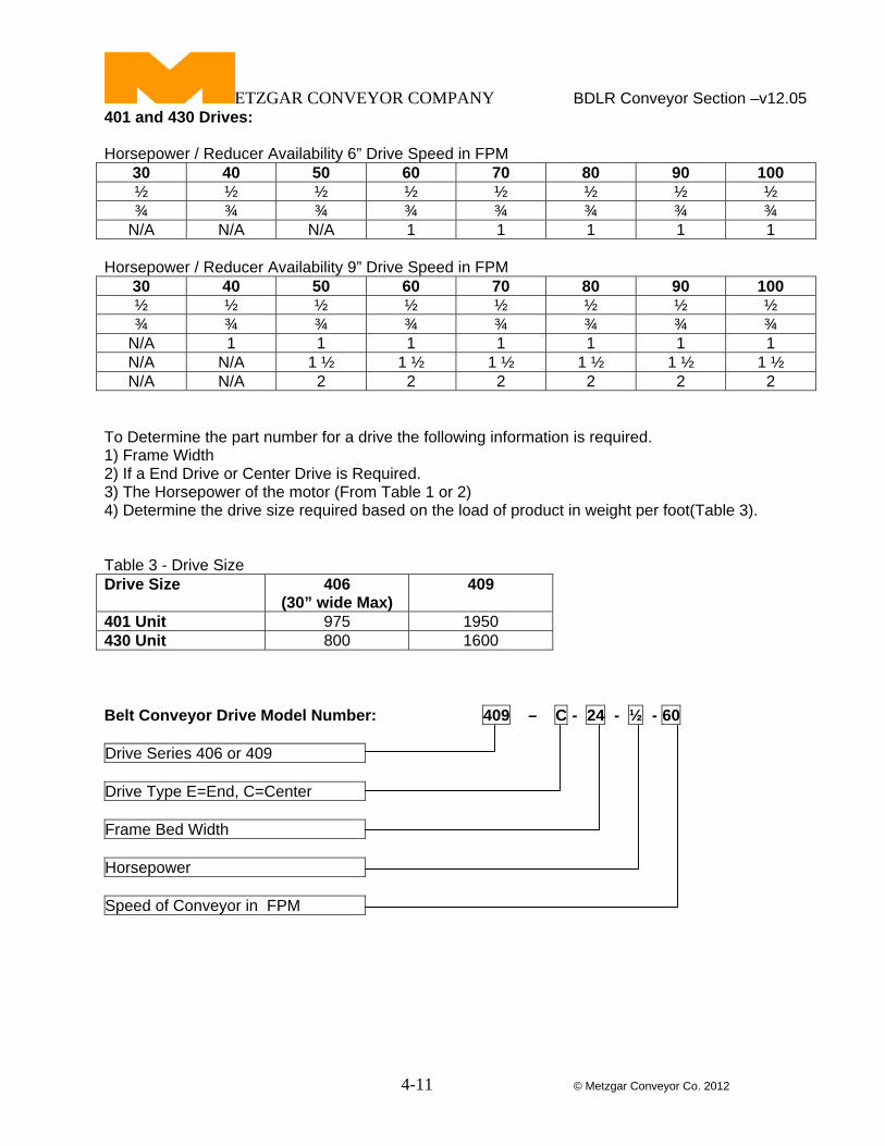
401 and 430 Drives: Horsepower / Reducer Availability 6” Drive Speed in FPM
30 40 50 60 70 80 90 100 ½ ½ ½ ½ ½ ½ ½ ½ ¾ ¾ ¾ ¾ ¾ ¾ ¾ ¾
N/A N/A N/A 1 1 1 1 1 Horsepower / Reducer Availability 9” Drive Speed in FPM
30 40 50 60 70 80 90 100 ½ ½ ½ ½ ½ ½ ½ ½ ¾ ¾ ¾ ¾ ¾ ¾ ¾ ¾
N/A 1 1 1 1 1 1 1 N/A N/A 1 ½ 1 ½ 1 ½ 1 ½ 1 ½ 1 ½ N/A N/A 2 2 2 2 2 2
To Determine the part number for a drive the following information is required. 1) Frame Width 2) If a End Drive or Center Drive is Required. 3) The Horsepower of the motor (From Table 1 or 2) 4) Determine the drive size required based on the load of product in weight per foot(Table 3). Table 3 - Drive Size Drive Size 406
(30” wide Max) 409
401 Unit 975 1950 430 Unit 800 1600 Belt Conveyor Drive Model Number: 409 – C - 24 - ½ - 60 Drive Series 406 or 409 Drive Type E=End, C=Center Frame Bed Width Horsepower Speed of Conveyor in FPM

ETZGAR CONVEYOR COMPANY
4-12 © Metzgar Conveyor Co. 2012
BDLR Conveyor Section –v12.05 Drive Dimensions and End Pulley Part Numbers : 401/430 End Drives Drive Pulley
“A” Dim.
6” Dia. 9 9” Dia. 12 401/430 Center Drives: Drive Pulley
“A” Dim.
“B” Dim.
“C” Dim.
6” Dia. 13” 7” 28” 9” Dia. 21 ½” 13” 32” 401/430 End Pulley Assembly: Pulley Diameter: 4 inch Bearings: Internal to Pulley Shaft Diameter: 1 3/16” One end pulley is required on an end drive conveyor. Two end pulleys are required on a center drive unit. End Pulley Model Number: 401EP - 24
Conveyor Series End Pulley Frame Bed Width

ETZGAR CONVEYOR COMPANY
4-13 © Metzgar Conveyor Co. 2012
BDLR Conveyor Section –v12.05 401/430 Belt Take-ups: Horizontal Take-up: A horizontal take-up should be used on end drives with one adjustable tail pulley on conveyors 40 feet in length up to 110 feet in length. A horizontal take-up should be used on end drives without an adjustable tail pulley on conveyors 10 feet in length up to 75 feet in length. Horizontal Take-up Model Number: 401 - HTU - 24
Conveyor Series Horizontal Take-up Frame Bed Width Standard unit includes a take-up frame assembly with snubber roller, two 4” diameter pulleys with 1 3/16” diameter shafts and guards. Vertical Take-up: A vertical take-up should be used on end drives with one adjustable tail pulley on conveyors 40 feet in length up to 80 feet in length. A vertical take-up should be used on end drives without an adjustable tail pulley on conveyors 10 feet in length up to 40 feet in length. Vertical Take-up Model Number: 401 - VTU - 24
Conveyor Series Vertical Take-up Frame Bed Width Standard unit includes a take-up frame assembly with two snubber rollers, one 4” diameter pulley with 1 3/16” diameter shafts and guards.

ETZGAR CONVEYOR COMPANY BDLR Conveyor Section –v12.05
4-14 © Metzgar Conveyor Co. 2012
435 Zero Pressure Electronic Accumulating BDLR Elevation Example and Features: Features: - Zero Pressure product accumulation. - Efficient full-length accumulation without gaps between products regardless of variations in product lengths. - End Pulley assemblies are integrated into the frame. - Systems Require 24vdc and 20 PSI compressed air - Electronic Sensors – no mechanical adjustments required. - Drives have a standard three phase motor. - Ability to slave drive a 450 Series V-Belt Driven Curve. - Standard unit has Pressure/drive rollers on 12” centers with electronic sensors on 24” centers. - Optional brake zones allow for positive stopping of rollers. Accumulation: 435 Series accumulation is accomplished using air pucks to raise the drive belt to contact the rollers for drive. Electronic sensors are used to sense the product and remove air from the puck, lowering the drive rollers. When two consecutive sensors are blocked the drive is removed from the upstream zone. Discharge: The discharge can be accomplished by two methods. 1) Singulation release, which the products are released one at a time with a gap between. (Shown in Example) 2) Slug release, which all the products are released creating a continuous flow of product.

ETZGAR CONVEYOR COMPANY BDLR Conveyor Section –v12.05
4-15 © Metzgar Conveyor Co. 2012
435 Zero Pressure Electronic Accumulating BDLR Specifications and Unit Model Number:
“A” Bed
Width
“B” Between
Frame 18” 15 ½” 24” 21 ½” 30” 27 ½” 36” 33 ½” 42” 39 ½” 48” 45 ½”
Belt: 4” PVC Cover One Side x Slider Back with Cover Down, v-guide molded to back side. Frame: 10 gage x 6 1/2” deep formed steel channel with 1 ¼”” flange. Frames are bolted together using formed steel crossmembers. Frames have hex slots for accumulation punched on 3” centers. Carrier Rollers: Rollers are 1.9” diameter x 16 gage steel with ball bearings and 7/16”
hex axles. Axles are spring loaded for easy assembly or removal. Carrier rollers are available on 3” or 6” Centers.
Drive Pulleys: Standard Drive pulley is 8” diameter with v-guide. Drive pulley shafts are 1 3/16” dia for 8” drive. End Pulleys and Take-up Pulleys: 4” diameter with v-guide. Drive Snubber Roller: Rollers are 2 ½” diameter with ball bearings. Belt return Idler Rollers: Rollers are 1.9” diameter x 16 gage steel with ball bearings and 7/16”
hex axles. Axles are spring loaded for easy assembly or removal. Belt Speed: 60 Feet Per Minute (FPM) is the most common. Other speeds and variable speed are available as options. 435 Belt Driven Conveyor Model Number: 435 – C - 18 - 3 - 25 - ¾
Conveyor Series Drive Type C=Center Overall Frame Bed Width Carrier Roller Centers(3”,6”) Overall Unit Length in Feet-Inches Motor Horsepower Optional 8” wide belt is available for heavy load applications. Order Separately: Brakes, Guard Rail, Supports and Controls.

ETZGAR CONVEYOR COMPANY BDLR Conveyor Section –v12.05
4-16 © Metzgar Conveyor Co. 2012
450 Series Tapered Roller Curves:
Maximum Drive per Roller is 13 pounds. Maximum Weight of product on curve is 250 pounds. 450 Curves are available in 18”, 24”, 30”, 36”and 42” OAW . Curve Model Number: 450C - 24 - 90
BDLR Series Number Overall Frame Width Degree of Curve (30°,45°,60°& 90°) 450 Series Tapered Roller Curve: Tapered Rollers: 1-5/8” Diameter on small end with 7/16” hex axle with ball bearings. Tapered Rollers have .042” of taper per inch of length to the large end. Roller ends are swaged over the bearings to provide a smooth, full length carrying surface. Roller axles are 7/16” hex stock spring loaded for easy removal and assembly. The top of the roller is 5/16” above the top flange of the frame. Frame: 10 gage formed channel 4-1/2” deep with 1-1/4” flanges. Axle holes are 7/16” hex. Crossmembers are formed 10 gage steel bolted to frames. Drive Belt: B-Section Endless V-Belt Motor/Drive: ½ Hp for 60 Feet Per Minute is standard. Finish: Standard finish for painted components is Metzgar Medium Blue or Vista Green Standard Curves Contain 20 Rollers in a 90 Degree Curve. 30° and 45° Curves include a 12” tangent section as standard. Order Separately: Guard Rail, Supports and Controls. Standard Speed is 60 FPM consult factory for other speeds.

ETZGAR CONVEYOR COMPANY BDLR Conveyor Section –v12.05
4-17 © Metzgar Conveyor Co. 2012
450 Series Curve Tangents:
Maximum Drive per Roller is 9 pounds with Tangent added. Maximum Weight of product on curve and Tangent is 250 pounds. 450 Curve Tangents are available in 18”, 24”, 30”, 36”and 42” OAW . Curve Model Number: 450S - 24 - 4
BDLR Series Number Overall Frame Width Length of Tangent in Feet (4’max.) 450 Series Straight Roller Curve Tangent: Straight Rollers: 1.9” Diameter x 16 gage galvanized tube. Roller ends are swaged over the bearings to provide a smooth, full length carrying surface. Roller axles are 7/16” hex stock spring loaded for easy removal and assembly. The top of the roller is 5/16” above the top flange of the frame. Frame: 10 gage formed channel 4-1/2” deep with 1-1/4” flanges. Axle holes are 7/16” hex. Crossmembers are formed 10 gage steel bolted to frames. Drive Belt: B-Section Endless V-Belt Motor/Drive: Included on Curve Finish: Standard finish for painted components is Metzgar Medium Blue or Vista Green

ETZGAR CONVEYOR COMPANY BDLR Conveyor Section –v12.05
4-18 © Metzgar Conveyor Co. 2012
450 Series 90 Degree Spur/ Merge:
OAW “A” “B” 18” 67 ¼” 52 24” 72 ¼” 59 ½ 30” 91 ¼” 73 ¼” 36” 103 ½” 83 ½” 42 115 ½” 94
Maximum Drive per Roller is 13 pounds. Maximum Weight of product on Spur / Merge is 250 pounds. 450 90° Spur / Merges are available in 18”, 24”, 30”, 36”and 42” OAW . Spur Model Number: 450-LRS - 24 - 90 - RH
BDLR Series Number Frame Width Degree of Curve Right Hand or Left Hand (RH or LH) 450 Series 90 Degree Spur / Merge: Tapered Rollers: 1-5/8” Diameter on small end with 7/16” hex axle with ball bearings. Tapered Rollers have .042” of taper per inch of length to the large end. Roller ends are swaged over the bearings to provide a smooth, full length carrying surface. Roller axles are 7/16” hex stock spring loaded for easy removal and assembly. The top of the roller is 5/16” above the top flange of the frame. Straight Rollers: 1.9” diameter x 16 gage galvanized tube with 7/16” hex axle with ball bearings. Roller ends are swaged over the bearings to provide a smooth, full length carrying surface. Roller grooves are cold formed in the roller shell. Roller axles are 7/16” hex stock spring loaded for easy removal and assembly Frame: 10 gage formed channel 4-1/2” deep with 1-1/4” flanges. Axle holes are 7/16” hex. Crossmembers are formed 10 gage steel bolted to frames. Drive Belt: B-Section Endless V-Belt Motor/Drive: ½ Hp for 60 Feet Per Minute is standard. Finish: Standard finish for painted components is Metzgar Medium Blue or Vista Green Order Separately:Guard Rail, Supports, Turning Wheel and Controls. Standard Speed is 60 FPM consult factory for other speeds.

ETZGAR CONVEYOR COMPANY BDLR Conveyor Section –v12.05
4-19 © Metzgar Conveyor Co. 2012
450 Series 45 Degree Spur/ Merge:
OAW “A” “B” 18” 27” 40 ½” 24” 29 ¼” 38 ¼” 30” 31 ¼” 44 ½” 36” 33 ½” 51 42 35 ½” 65 ½”
Maximum Drive per Roller is 13 pounds. Maximum Weight of product on Spur / Merge is 250 pounds. 450 45° Spur / Merges are available in 18”, 24”, 30”, 36”and 42” OAW . Spur Model Number: 450-LRS - 24 - 45 - RH
BDLR Series Number Frame Width Degree of Curve Right Hand or Left Hand (RH or LH) 450 Series 45 Degree Spur / Merge: Straight Rollers: 1.9” diameter x 16 gage galvanized tube with 7/16” hex axle with ball bearings. Roller ends are swaged over the bearings to provide a smooth, full length carrying surface. Roller grooves are cold formed in the roller shell. Roller axles are 7/16” hex stock spring loaded for easy removal and assembly Frame: 10 gage formed channel 4-1/2” deep with 1-1/4” flanges. Axle holes are 7/16” hex. Crossmembers are formed 10 gage steel bolted to frames Drive Belt: B-Section Endless V-Belt Motor/Drive: ½ Hp for 60 Feet Per Minute is standard. Finish: Standard finish for painted components is Metzgar Medium Blue or Vista Green Order Separately:Guard Rail, Supports, Turning Wheel and Controls. Standard Speed is 60 FPM consult factory for other speeds.

ETZGAR CONVEYOR COMPANY BDLR Conveyor Section –v12.05
4-20 © Metzgar Conveyor Co. 2012
460 Heavy Duty Belt Driven Live Roller Conveyor Specifications and Unit Model Number:
“A” Bed
Width
“B” Between
Frame
“C” Roller Width
42 ¼” 39” 38 ¾” 46 ¼” 43” 42 ¾” 50 ¼” 47” 15 ¼” 54 ¼” 51” 50 ¾” 58 ¼” 55” 54 ¾” 62 ¼” 59” 58 ¾” 66 ¼” 63” 62 ¾” 70 ¼” 67” 66 ¾” 74 ¼” 71” 70 ¾”
Belt: 18” wide PVC Cover One Side x Slip Back with Cover Up. Frame: 7 gage x 8” deep formed steel channel with 1 5/8” flange. Frames are welded together using 2” x 2” x 1/4” structural angle crossmembers. Frames are slotted for pop-out roller safety feature. Carrier Rollers: Rollers are 2 ½” diameter x 11 gage steel with ball bearings and 11/16”
hex axles. Axles are spring loaded for easy assembly or removal. Carrier rollers are available on 3”or 6” Centers. Roller capacity is 650 pounds each.
Drive Pulleys: Standard Drive pulleys come in 10” diameter crowned and lagged. Drive pulley shaft is 1 15/16” dia.
Standard Drive motor is located on the Left side looking with the direction of flow. End Pulleys and Take-up Pulleys: 6” diameter crowned with 1 7/16: dia. shaft.
External mounted bearings are standard. Drive Snubber Roller: Rollers are 2 ½” diameter 11 gage steel with ball bearings and
11/16” hex tube spanner and 7/16” diameter shaft. Belt return Idler Rollers: Rollers are 2 ½” diameter x 11 gage steel with ball bearings and 11/16”
hex axles. Axles are spring loaded for easy assembly or removal. Standard Speed: 30 Feet Per Minute (FPM). Other speeds and variable speed are available as options. 460 Belt Driven Conveyor Model Number: 460 – E - 50 - 3 - 25 - ¾
Conveyor Series Drive Type E= End C=Center Frame Bed Width Carrier Roller Centers(3” or 6”) Overall Unit Length in Feet-Inches Motor Horsepower

ETZGAR CONVEYOR COMPANY BDLR Conveyor Section –v12.05
4-21 © Metzgar Conveyor Co. 2012
460 Bed Selection, Belt Length and End Pulley
460 Bed Section Model Number: 460 - 50 - 3
Conveyor Series Frame Bed Width Roller Centers(2.4”, 3”, 4” or 6”) 460 Belt Length Chart Model Equipment Description Length of Belt Req’d 460 10” End Drive 2’-8” 460 6” Diameter End Pulley 2’-6”
Determining the length of the Belt for a particular unit: 1) Take the length of all bed sections and multiply by two. 2) Add the length of the end assembly and drive. 460 End Pulley Assembly Pulley Diameter: 6 inch Bearings: External with 6” travel of take-up Shaft Diameter: 1 7/16” End Pulley Model Number: 460EP - 50
Conveyor Series End Pulley Frame Bed Width

ETZGAR CONVEYOR COMPANY BDLR Conveyor Section –v12.05
4-22 © Metzgar Conveyor Co. 2012
460 Horsepower Section: To Determine the Horsepower required on a 460 Series BDLR Unit: 1) Determine the maximum weight of product that will be on the unit at any time. 2) Divide the maximum weight by the unit length to get weight per foot 3) Use Table 3 below to determine the estimated horsepower required at 40 FPM. Table 3 – 460 Series Horsepower for Maximum Load in weight per foot Rollers on 3” Centers.
Unit Width HP 20’ 30’ 40’ 50’ 60’ 70’ 80’ 90’ ¾ 119 35 22 1 179 94 52 26 9
1 ½ 319 187 122 82 56 37 23 12
42
2 428 260 176 126 92 68 51 37 ¾ 113 48 15 1 172 88 45 20
1 ½ 312 181 115 76 50 31 17
46
2 421 254 170 119 86 62 44 30 ¾ 107 42 9 1 166 81 39 14
1 ½ 306 175 109 70 43 25 11
50
2 415 247 164 113 80 56 38 24 ¾ 100 36 1 160 75 33
1 ½ 300 169 103 64 37 18
54
2 409 241 157 107 74 50 32 18 ¾ 94 29 1 153 69 26
1 ½ 293 162 96 57 31 12
58
2 402 235 151 101 67 43 25 11 ¾ 88 23 1 147 63 20
1 ½ 287 156 90 51 25
62
2 396 228 145 94 61 37 19 ¾ 82 17 1 141 56 14
1 ½ 281 150 84 45 18
66
2 390 222 139 88 55 31 13 ¾ 76 11 1 135 50
1 ½ 275 144 78 39 12
70
2 384 216 133 82 49 25 ¾ 69 1 129 44
1 ½ 269 137 72 32
74
2 378 210 126 76 42 19
For Loads that are greater than listed in this table consult the factory. Tables are based on 40 Feet Per Minute.

ETZGAR CONVEYOR COMPANY BDLR Conveyor Section –v12.05
4-23 © Metzgar Conveyor Co. 2012
460 Horsepower Section: To Determine the Horsepower required on a 460 Series BDLR Unit: 1) Determine the maximum weight of product that will be on the unit at any time. 2) Divide the maximum weight by the unit length to get weight per foot 3) Use Table 4 below to determine the estimated horsepower required at 40 FPM. Table 4 – 460 Series Horsepower for Maximum Load in weight per foot Rollers on 6” Centers.
Unit Width HP 20’ 30’ 40’ 50’ 60’ 70’ 80’ 90’ ¾ 147 82 50 31 18 8 1 207 122 80 54 37 25 16
1 ½ 347 215 150 110 84 65 51 40
42
2 456 288 204 154 120 97 79 65 ¾ 143 78 46 27 14 1 203 118 76 50 33 21 12
1 ½ 343 211 146 106 80 61 47 36
46
2 452 284 200 150 116 93 75 61 ¾ 140 75 42 23 10 1 199 114 72 45 30 18 9
1 ½ 339 208 142 103 76 58 44 33
50
2 448 280 197 146 113 89 71 57 ¾ 136 72 39 19 1 195 110 68 43 26 14
1 ½ 335 204 138 99 73 54 40 29
54
2 444 278 193 143 109 85 67 53 ¾ 132 67 35 15 1 191 107 64 39 22 10
1 ½ 331 200 134 95 69 50 36 25
58
2 440 273 189 139 105 81 63 49 ¾ 128 63 31 11 1 188 103 61 35 18 6
1 ½ 328 196 131 91 65 46 32 21
62
2 437 269 185 135 101 77 59 45 ¾ 124 60 27 8 1 184 99 57 32 15
1 ½ 324 193 127 88 61 42 28 17
66
2 433 265 181 131 98 74 56 42 ¾ 121 56 23 1 180 95 53 28 11
1 ½ 320 189 123 84 57 39 25 14
70
2 429 261 178 127 94 70 52 38 ¾ 117 52 20 1 176 92 49 24 7
1 ½ 316 185 119 80 54 35 21 10
74
2 425 258 174 124 90 66 48 34
For Loads that are greater than listed in this table consult the factory. Tables are based on 40 Feet Per Minute.

ETZGAR CONVEYOR COMPANY BDLR Conveyor Section –v12.05
4-24 © Metzgar Conveyor Co. 2012
460 Belt Driven Live Roller Drive Model Number: Horsepower / Reducer Availability 460 Drive Speed in FPM
30 35 40 45 50 55 60 ¾ ¾ ¾ ¾ ¾ ¾ ¾ ¾ ¾ ¾ ¾ ¾ ¾ ¾ 1 1 1 1 1 1 1
1 ½ 1 ½ 1 ½ 1 ½ 1 ½ 1 ½ 1 ½ 2 2 2 2 2 2 2
Belt Driven Conveyor Drive Model Number: 460 – E - 2418 - ¾ - 30 Drive Series Drive Type (see below) Frame Bed Width Horsepower Speed of Conveyor in FPM

ETZGAR CONVEYOR COMPANY BDLR Conveyor Section –v12.05
4-25 © Metzgar Conveyor Co. 2012
Belt Driven Live Roller Options: Frame Options: Butt Bolt Frame Connectors Special Widths to match an Existing Conveyor Special Degree Curves Special Paint Colors Powder Coated Frames Bright Zinc Plating on Frames Full Width End Covers Full Width End Cover Stops Roller Options: Special Roller Lengths Powder Coated Rollers Bright Zinc Plating on Rollers Semi Precision Roller Bearings ABEC-1 Precision Roller Bearings Drive Options: Single or Three Phase Motors Clutch/Brake Assemblies

ETZGAR CONVEYOR COMPANY BDLR Conveyor Section –v12.05
4-26 © Metzgar Conveyor Co. 2012
BDLR Replacement Parts: 6” Drive Pulleys (5” Diameter plus Lagging) Includes 1 3/16” Diameter Shaft Overall Width Face Width Pulley with 1 3/16” Bore
12” 7” 406-12Dpulley 15” 10” 406-15Dpulley 18” 13” 406-18Dpulley 24” 19” 406-24Dpulley 30” 25” 406-30Dpulley 36” 31” 406-36Dpulley 42” 37” 406-42Dpulley 48” 43” 406-48Dpulley
9” Drive Pulleys (8” Diameter plus Lagging) Includes 1 7/16” Diameter Shaft Overall Width Face Width Pulley with 1 7/16” Bore
12” 7” 409-12Dpulley 15” 10” 409-18Dpulley 18” 13” 409-18Dpulley 24” 19” 409-24Dpulley 30” 25” 409-30Dpulley 36” 31” 409-36Dpulley 42” 37” 409-42Dpulley 48” 43” 409-48Dpulley
4” Take-up End Pulley (4” Diameter with Internal Bearings) Includes 1 3/16” Diameter Shaft Overall Width Face Width Pulley with 1 3/16” Bore
12” 7” 401-12-419TUEpulley 15” 10” 401-15-419TUEpulley 18” 13” 401-18-419TUEpulley 24” 19” 401-24-419TUEpulley 30” 25” 401-30-419TUEpulley 36” 31” 401-36-419TUEpulley 42” 37” 401-42-419TUEpulley 48” 43” 401-48-419TUEpulley
401/430 Drive Snubber Roller Overall Width Snubber Rollers Steel
12 ” 401-12SRS 15” 401-15SRS 18” 401-18SRS 24” 401-24SRS 30” 401-30SRS 36” 401-36SRS 42” 401-42SRS 48” 401-48SRS
401 and 430 Return Rollers and 401 Carrier Rollers with 7/16” Hex Shaft (Return Roller Bracket ordered Separate) Overall Width Return Rollers Steel
12” 401-12RRS 15” 401-15RRS 18” 401-18RRS 24” 401-24RRS 30” 401-30RRS 36” 401-36RRS 42” 401-42RRS 48” 401-48RRS
430 Carrier Rollers with 7/16” Hex Shaft Overall Width Carrier Rollers Steel
12” 430-12CRS 15” 430-15CRS 18” 430-18CRS 24” 430-24CRS 30” 430-30CRS 36” 430-36CRS 42” 430-42CRS 48” 430-48CRS

ETZGAR CONVEYOR COMPANY BDLR Conveyor Section –v12.05
4-27 © Metzgar Conveyor Co. 2012
401/430 Misc Parts BDLR Return Carrier Bracket 401-RCA 430 Accumulator Sintered Bushing 430-SAB 435 Carrier Rollers with 7/16” Hex Shaft Overall Width Carrier Rollers Steel
18” 435-18RS 24” 435-24RS 30” 435-30RS 36” 435-36RS 42” 435-42RS 48” 435-48RS
435 Misc Parts Electronic Sensor Photoeye/Solenoid Valve 435-PESOL 435 Air Bladder/Puck 435-PUCK 435 4” Wide V-guide Belt x Length 435-Vbelt x __ft 450 Series Tapered Rollers:
Overall Width Tapered Steel With No Grooves 18 450-18-TRS-NG 24 450-24-TRS-NG 30 450-30-TRS-NG 36 450-36-TRS-NG 42 450-42-TRS-NG
450 Misc Parts 450 End Drive Shive with Molded Tire 450-DSMT 450 Pressure Shive D-8040 450-PS 450 Reducer Mounted Drive Shive 450-RMDS 450 Idler Shive ( All Sizes ) 450-IS 460 Rollers 2 ½” x 11 gage with 11/16 hex Axles Overall Width Snubber Rollers Steel
42 ¼” 460-42SRS 46 ¼” 460-46SRS 50 ¼” 460-50SRS 54 ¼” 460-54SRS 58 ¼” 460-58SRS 62 ¼” 460-62SRS 66 ¼” 460-66SRS 70 ¼” 460-70SRS 74 ¼” 460-74SRS
460 10” Drive Pulleys (10” Diameter plus Lagging) Includes 1 15/16” Diameter Shaft Overall Width Face Width Pulley with 1 15/16” Bore
42 ¼” 37” 460-42Dpulley 46 ¼” 41” 460-46Dpulley 50 ¼” 45” 460-50Dpulley 54 ¼” 49” 460-54Dpulley 58 ¼” 53” 460-58Dpulley 62 ¼” 57” 460-62Dpulley 66 ¼” 61” 460-66Dpulley 70 ¼” 65” 460-70Dpulley 74 ¼” 69” 460-74Dpulley
460 6” End Pulleys Includes 1 7/16” Diameter Shaft Overall Width Face Width Pulley with 1 7/16” Bore
42 ¼” 37” 460-42TUEpulley 46 ¼” 41” 460-46TUEpulley 50 ¼” 45” 460-50TUEpulley 54 ¼” 49” 460-54TUEpulley 58 ¼” 53” 460-58TUEpulley 62 ¼” 57” 460-62TUEpulley 66 ¼” 61” 460-66TUEpulley 70 ¼” 65” 460-70TUEpulley 74 ¼” 69” 460-74TUEpulley

ETZGAR CONVEYOR COMPANY BDLR Conveyor Section –v12.05
4-28 © Metzgar Conveyor Co. 2012
Bearings ID of Bearing Part Number
1 3/16” 406-4hole19 1 7/16” 409-4hole23
1 15/16” 460-4hole31 1 7/16” 460-ETU23
Chain Guards
Drive Part Number 406 Plastic 406-PCG 409 Plastic 409-PCG 460-Steel 460-SCG
Chain Parts: 50B12T to 50B35T Standard Sprockets for #50 Chain
50-Chain Feet of #50 Roller Chain 60B11T to 60B36T Standard Sprockets for #60 Chain
60-Chain Feet of #60 Roller Chain 80B12T to 80B30T Standard Sprockets for #80 Chain
80-Chain Feet of #80 Roller Chain Touch-Up Paint
MB-SPaint Spray Can of Metzgar Blue Touch-up Paint MB-1gCPaint One Gallon Can of Metzgar Blue Touch-up Paint
VG-SPaint Spray Can of Vista Green Touch-up Paint VG-1gCPaint One Gallon Can of Vista Green Touch-up Paint