etzgar conveyor company - conveyor · pdf fileetzgar conveyor company line shaft conveyor...
TRANSCRIPT
ETZGAR CONVEYOR COMPANY Line Shaft Conveyor Section – v12.05
2-1 © Metzgar Conveyor Co. 2012
Section 2 – Line Shaft Powered Conveyor Page Description 2-1 Line Shaft Index 2-2 Basic Components 2-3 Introduction 2-4 Application Data 2-5 438 Series Specifications (1-3/8” Diameter Rollers) 2-6 440 Series Specifications (1.9” Diameter Rollers) 2-7 438 and 440 Horsepower Chart 2-8 438 and 440 Drive Packages 2-9 438 and 440 Curves 2-10 438 and 440 30-Degree Spurs 2-11 438 and 440 45-Degree Merge 2-12 438 and 440 90-Degree Belt Transfer 2-13 440 Roller Switch 2-14 438 and 440 Gate 2-15 438 and 440 Accessories 2-16 443 Series Specifications (2-1/2” Diameter Rollers, Mattress Style) 2-17 443 Horsepower Chart and Drive Packages 2-18 443 Curves 2-19 443 90-Degree Transfer 2-20 445 Series Specifications (2-1/2” Diameter Rollers) 2-21 445 Horsepower Chart and Drive Packages 2-22 Line Shaft Frame and Roller Options 2-23 438/440 Series Replacement Parts 2-24 438/440 and 443 Series Replacement Parts 2-25 445 and Misc. Lineshaft Series Replacement Parts
ETZGAR CONVEYOR COMPANY Line Shaft Conveyor Section – v12.05
2-2 © Metzgar Conveyor Co. 2012
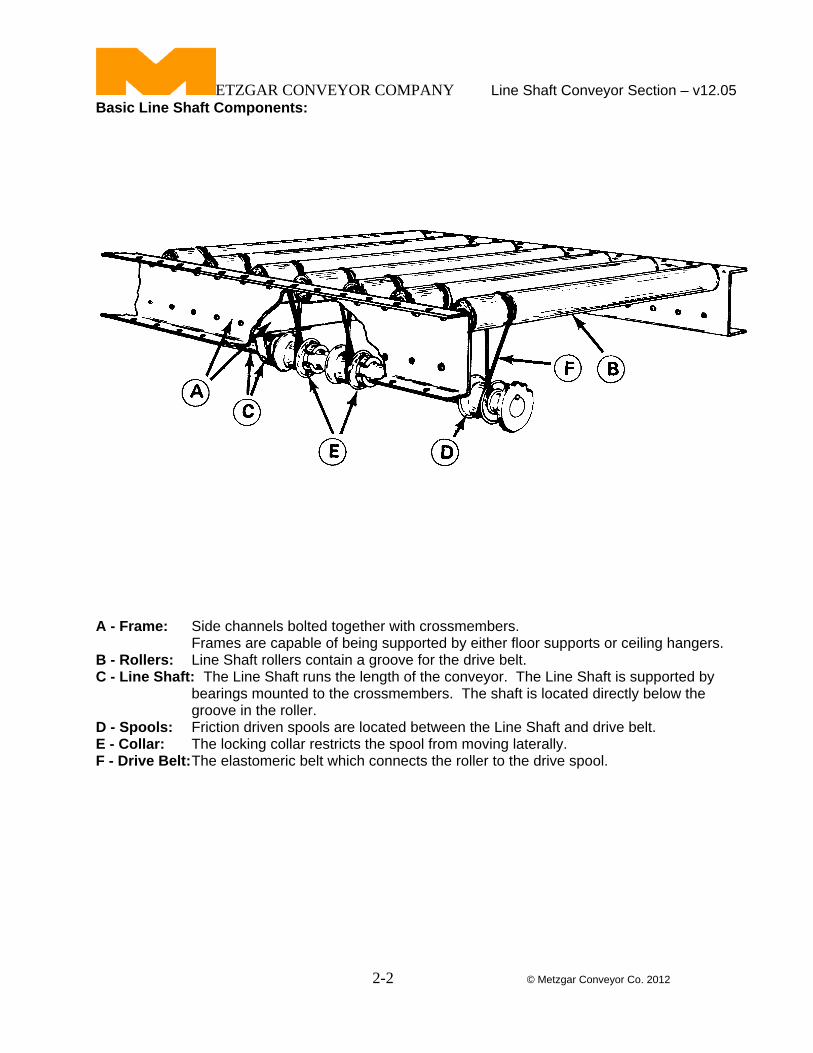
Basic Line Shaft Components:
A - Frame: Side channels bolted together with crossmembers. Frames are capable of being supported by either floor supports or ceiling hangers. B - Rollers: Line Shaft rollers contain a groove for the drive belt. C - Line Shaft: The Line Shaft runs the length of the conveyor. The Line Shaft is supported by
bearings mounted to the crossmembers. The shaft is located directly below the groove in the roller.
D - Spools: Friction driven spools are located between the Line Shaft and drive belt. E - Collar: The locking collar restricts the spool from moving laterally. F - Drive Belt: The elastomeric belt which connects the roller to the drive spool.
ETZGAR CONVEYOR COMPANY Line Shaft Conveyor Section – v12.05
2-3 © Metzgar Conveyor Co. 2012
Introduction:
The Metzgar “Line Shaft Conveyor” is a live roller conveyor that is suitable for light to medium service of product loads up to 40 pounds per roller. Please consult the factory for heavier loads. This conveyor design is a substantial improvement over conventional live roller conveyors which use either belt or chain drives. We power rollers individually, allowing an almost unlimited variety of hardware and system applications. Line Shaft conveyor utilizes a drive shaft, which runs the length of the conveyor. Torque created in the “slip fit” pulleys from the rotating shaft is used to power each roller individually. The pulleys, or drive spools are held in place by “positioning collars” that assist the rollers individual drive capabilities. This is important when using the conveyor in “transportation”, “minimum pressure accumulation” and “zero pressure accumulation” operating modes. Power is transmitted to each roller from the spool by a urethane composition belt.
One significant advantage of this type of live roller conveyor is the ability to direct the shaft around curves, as a power source for several devices such as spurs and transfers. The reduction of drive components makes it economical and very attractive to the customer. Advantages of using Line Shaft Conveyor: There is plenty of drive to move the product, however if a foreign object becomes caught between the rollers, each roller, drive spool and belt will operate as a safety slip clutch. A full-length safety guard is provided around the rotating shaft. Rollers can be assembled in sections to rotate in opposite directions, to achieve bi-directional travel at the same time on one unit. This conveyor can be used for minimum pressure accumulation because the rollers do not usually rotate under a stopped package. The design allows accumulation with significantly less pressure than conventionally driven live roller conveyors. The design also allows for zero pressure accumulation with absolutely no pressure or contact between products being accumulated. The product can be released in “singulation” or “slug” modes. The unique drive system eliminates pressure rollers and flat belt surfaces that create dirt-grime gathering areas. Conveyor rollers touch only the product they convey. Metzgar Line Shaft Conveyor with special surface finishes, meets actual Class100 clean room cleanliness requirements. Line Shaft conveyor is much quieter than conventional live roller conveyors. There are fewer moving parts to make noise. The elastomeric drive belts hold the rollers firmly under tension, eliminating a major source of rattling in roller conveyors. In addition to performing functions of conventional live roller conveyors, the Line Shaft can be easily modified to perform a variety of special functions, formerly requiring expensive designs. The fact that straight sections, curves, spurs, transfers, etc. can be driven off a single motor; in some instances an entire system; means a considerable savings in the number of drives and electrical controls required, which reduces installation and energy consumption costs. To assist in maintaining control of transported items it is possible to skew individual rollers in order to position packages against a side guide.
ETZGAR CONVEYOR COMPANY Line Shaft Conveyor Section – v12.05
2-4 © Metzgar Conveyor Co. 2012
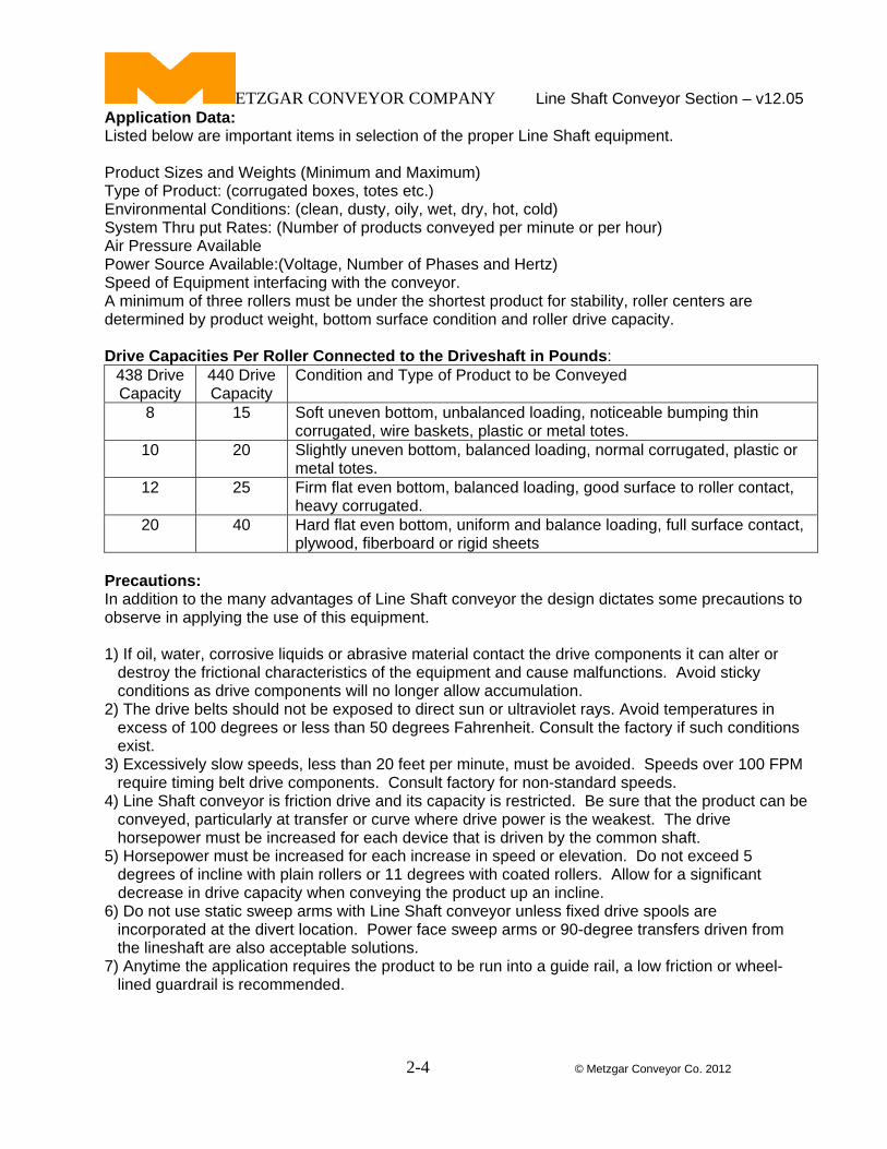
Application Data: Listed below are important items in selection of the proper Line Shaft equipment. Product Sizes and Weights (Minimum and Maximum) Type of Product: (corrugated boxes, totes etc.) Environmental Conditions: (clean, dusty, oily, wet, dry, hot, cold) System Thru put Rates: (Number of products conveyed per minute or per hour) Air Pressure Available Power Source Available:(Voltage, Number of Phases and Hertz) Speed of Equipment interfacing with the conveyor. A minimum of three rollers must be under the shortest product for stability, roller centers are determined by product weight, bottom surface condition and roller drive capacity. Drive Capacities Per Roller Connected to the Driveshaft in Pounds:
438 Drive Capacity
440 Drive Capacity
Condition and Type of Product to be Conveyed
8 15 Soft uneven bottom, unbalanced loading, noticeable bumping thin corrugated, wire baskets, plastic or metal totes.
10 20 Slightly uneven bottom, balanced loading, normal corrugated, plastic or metal totes.
12 25 Firm flat even bottom, balanced loading, good surface to roller contact, heavy corrugated.
20 40 Hard flat even bottom, uniform and balance loading, full surface contact, plywood, fiberboard or rigid sheets
Precautions: In addition to the many advantages of Line Shaft conveyor the design dictates some precautions to observe in applying the use of this equipment. 1) If oil, water, corrosive liquids or abrasive material contact the drive components it can alter or destroy the frictional characteristics of the equipment and cause malfunctions. Avoid sticky conditions as drive components will no longer allow accumulation. 2) The drive belts should not be exposed to direct sun or ultraviolet rays. Avoid temperatures in excess of 100 degrees or less than 50 degrees Fahrenheit. Consult the factory if such conditions exist. 3) Excessively slow speeds, less than 20 feet per minute, must be avoided. Speeds over 100 FPM require timing belt drive components. Consult factory for non-standard speeds. 4) Line Shaft conveyor is friction drive and its capacity is restricted. Be sure that the product can be conveyed, particularly at transfer or curve where drive power is the weakest. The drive horsepower must be increased for each device that is driven by the common shaft. 5) Horsepower must be increased for each increase in speed or elevation. Do not exceed 5 degrees of incline with plain rollers or 11 degrees with coated rollers. Allow for a significant decrease in drive capacity when conveying the product up an incline. 6) Do not use static sweep arms with Line Shaft conveyor unless fixed drive spools are incorporated at the divert location. Power face sweep arms or 90-degree transfers driven from the lineshaft are also acceptable solutions. 7) Anytime the application requires the product to be run into a guide rail, a low friction or wheel- lined guardrail is recommended.
ETZGAR CONVEYOR COMPANY Line Shaft Conveyor Section – v12.05
2-5 © Metzgar Conveyor Co. 2012
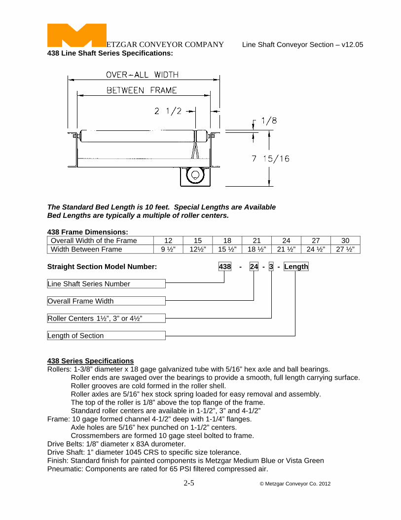
438 Line Shaft Series Specifications:
The Standard Bed Length is 10 feet. Special Lengths are Available Bed Lengths are typically a multiple of roller centers. 438 Frame Dimensions: Overall Width of the Frame 12 15 18 21 24 27 30 Width Between Frame 9 ½” 12½” 15 ½” 18 ½” 21 ½” 24 ½” 27 ½”
Straight Section Model Number: 438 - 24 - 3 - Length
Line Shaft Series Number Overall Frame Width Roller Centers 1½”, 3” or 4½” Length of Section 438 Series Specifications Rollers: 1-3/8” diameter x 18 gage galvanized tube with 5/16” hex axle and ball bearings. Roller ends are swaged over the bearings to provide a smooth, full length carrying surface. Roller grooves are cold formed in the roller shell. Roller axles are 5/16” hex stock spring loaded for easy removal and assembly. The top of the roller is 1/8” above the top flange of the frame. Standard roller centers are available in 1-1/2”, 3” and 4-1/2” Frame: 10 gage formed channel 4-1/2” deep with 1-1/4” flanges. Axle holes are 5/16” hex punched on 1-1/2” centers. Crossmembers are formed 10 gage steel bolted to frame. Drive Belts: 1/8” diameter x 83A durometer. Drive Shaft: 1” diameter 1045 CRS to specific size tolerance. Finish: Standard finish for painted components is Metzgar Medium Blue or Vista Green Pneumatic: Components are rated for 65 PSI filtered compressed air.
ETZGAR CONVEYOR COMPANY Line Shaft Conveyor Section – v12.05
2-6 © Metzgar Conveyor Co. 2012
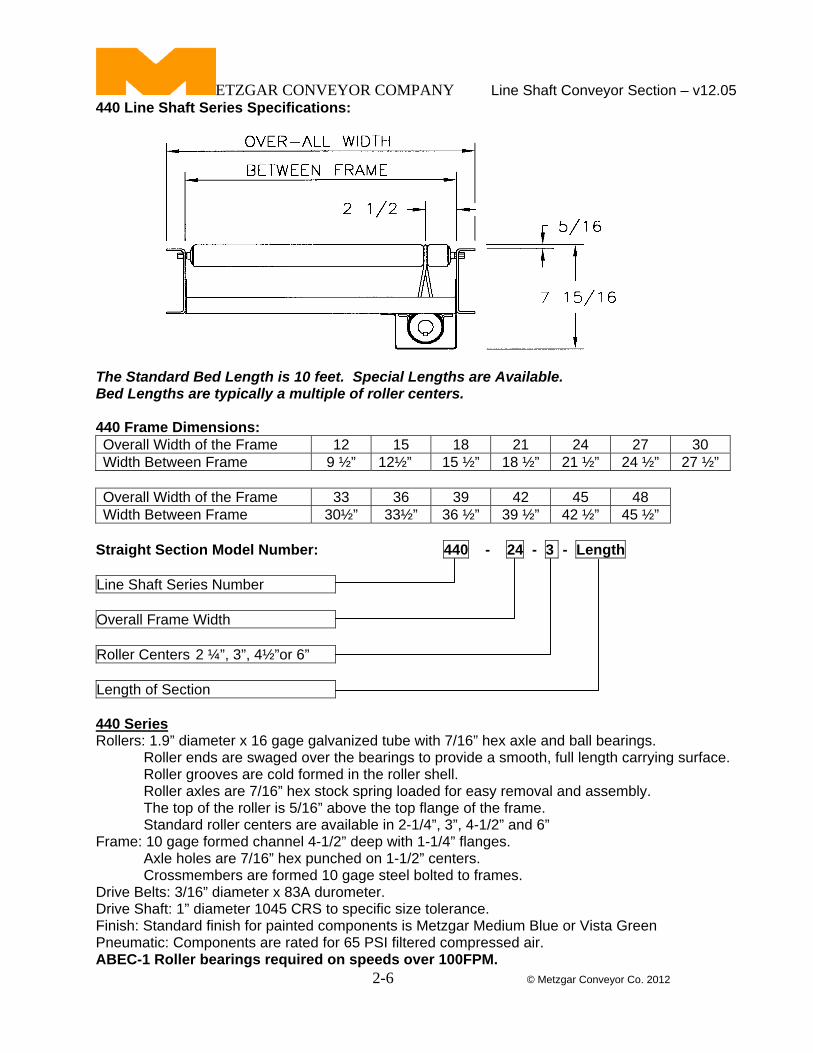
440 Line Shaft Series Specifications:
The Standard Bed Length is 10 feet. Special Lengths are Available. Bed Lengths are typically a multiple of roller centers. 440 Frame Dimensions: Overall Width of the Frame 12 15 18 21 24 27 30 Width Between Frame 9 ½” 12½” 15 ½” 18 ½” 21 ½” 24 ½” 27 ½”
Overall Width of the Frame 33 36 39 42 45 48 Width Between Frame 30½” 33½” 36 ½” 39 ½” 42 ½” 45 ½”
Straight Section Model Number: 440 - 24 - 3 - Length
Line Shaft Series Number Overall Frame Width Roller Centers 2 ¼”, 3”, 4½”or 6” Length of Section 440 Series Rollers: 1.9” diameter x 16 gage galvanized tube with 7/16” hex axle and ball bearings. Roller ends are swaged over the bearings to provide a smooth, full length carrying surface. Roller grooves are cold formed in the roller shell. Roller axles are 7/16” hex stock spring loaded for easy removal and assembly. The top of the roller is 5/16” above the top flange of the frame. Standard roller centers are available in 2-1/4”, 3”, 4-1/2” and 6” Frame: 10 gage formed channel 4-1/2” deep with 1-1/4” flanges. Axle holes are 7/16” hex punched on 1-1/2” centers. Crossmembers are formed 10 gage steel bolted to frames. Drive Belts: 3/16” diameter x 83A durometer. Drive Shaft: 1” diameter 1045 CRS to specific size tolerance. Finish: Standard finish for painted components is Metzgar Medium Blue or Vista Green Pneumatic: Components are rated for 65 PSI filtered compressed air. ABEC-1 Roller bearings required on speeds over 100FPM.
ETZGAR CONVEYOR COMPANY Line Shaft Conveyor Section – v12.05
2-7 © Metzgar Conveyor Co. 2012
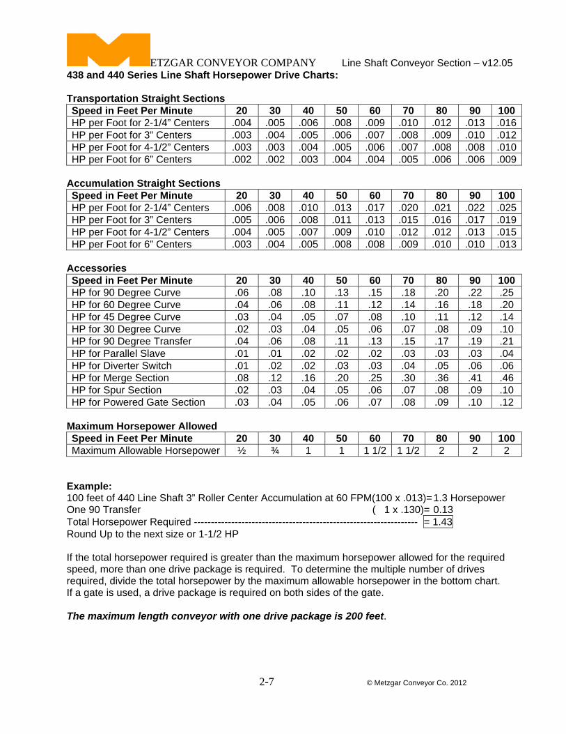
438 and 440 Series Line Shaft Horsepower Drive Charts: Transportation Straight Sections Speed in Feet Per Minute 20 30 40 50 60 70 80 90 100 HP per Foot for 2-1/4” Centers .004 .005 .006 .008 .009 .010 .012 .013 .016HP per Foot for 3” Centers .003 .004 .005 .006 .007 .008 .009 .010 .012HP per Foot for 4-1/2” Centers .003 .003 .004 .005 .006 .007 .008 .008 .010HP per Foot for 6” Centers .002 .002 .003 .004 .004 .005 .006 .006 .009
Accumulation Straight Sections Speed in Feet Per Minute 20 30 40 50 60 70 80 90 100 HP per Foot for 2-1/4” Centers .006 .008 .010 .013 .017 .020 .021 .022 .025HP per Foot for 3” Centers .005 .006 .008 .011 .013 .015 .016 .017 .019HP per Foot for 4-1/2” Centers .004 .005 .007 .009 .010 .012 .012 .013 .015HP per Foot for 6” Centers .003 .004 .005 .008 .008 .009 .010 .010 .013
Accessories Speed in Feet Per Minute 20 30 40 50 60 70 80 90 100 HP for 90 Degree Curve .06 .08 .10 .13 .15 .18 .20 .22 .25 HP for 60 Degree Curve .04 .06 .08 .11 .12 .14 .16 .18 .20 HP for 45 Degree Curve .03 .04 .05 .07 .08 .10 .11 .12 .14 HP for 30 Degree Curve .02 .03 .04 .05 .06 .07 .08 .09 .10 HP for 90 Degree Transfer .04 .06 .08 .11 .13 .15 .17 .19 .21 HP for Parallel Slave .01 .01 .02 .02 .02 .03 .03 .03 .04 HP for Diverter Switch .01 .02 .02 .03 .03 .04 .05 .06 .06 HP for Merge Section .08 .12 .16 .20 .25 .30 .36 .41 .46 HP for Spur Section .02 .03 .04 .05 .06 .07 .08 .09 .10 HP for Powered Gate Section .03 .04 .05 .06 .07 .08 .09 .10 .12
Maximum Horsepower Allowed Speed in Feet Per Minute 20 30 40 50 60 70 80 90 100 Maximum Allowable Horsepower ½ ¾ 1 1 1 1/2 1 1/2 2 2 2
Example: 100 feet of 440 Line Shaft 3” Roller Center Accumulation at 60 FPM(100 x .013)= 1.3 Horsepower One 90 Transfer ( 1 x .130)= 0.13 Total Horsepower Required ------------------------------------------------------------------ = 1.43 Round Up to the next size or 1-1/2 HP If the total horsepower required is greater than the maximum horsepower allowed for the required speed, more than one drive package is required. To determine the multiple number of drives required, divide the total horsepower by the maximum allowable horsepower in the bottom chart. If a gate is used, a drive package is required on both sides of the gate. The maximum length conveyor with one drive package is 200 feet.
ETZGAR CONVEYOR COMPANY Line Shaft Conveyor Section – v12.05
2-8 © Metzgar Conveyor Co. 2012
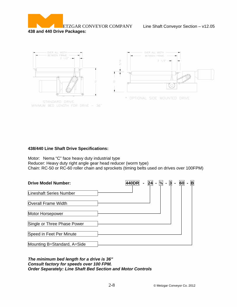
438 and 440 Drive Packages:
438/440 Line Shaft Drive Specifications: Motor: Nema “C” face heavy duty industrial type Reducer: Heavy duty right angle gear head reducer (worm type) Chain: RC-50 or RC-60 roller chain and sprockets (timing belts used on drives over 100FPM) Drive Model Number: 440DR - 24 - ¾ - 3 - 60 - B
Lineshaft Series Number Overall Frame Width Motor Horsepower Single or Three Phase Power Speed in Feet Per Minute Mounting B=Standard, A=Side The minimum bed length for a drive is 36” Consult factory for speeds over 100 FPM. Order Separately: Line Shaft Bed Section and Motor Controls
ETZGAR CONVEYOR COMPANY Line Shaft Conveyor Section – v12.05
2-9 © Metzgar Conveyor Co. 2012
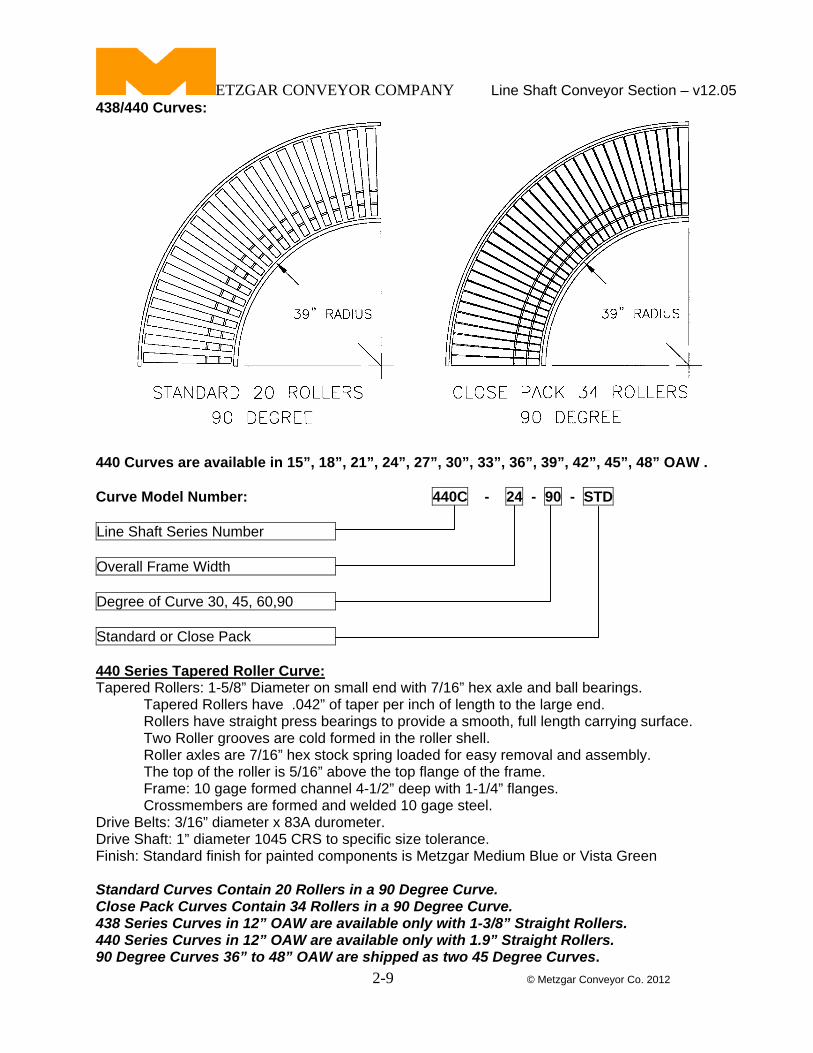
438/440 Curves:
440 Curves are available in 15”, 18”, 21”, 24”, 27”, 30”, 33”, 36”, 39”, 42”, 45”, 48” OAW . Curve Model Number: 440C - 24 - 90 - STD
Line Shaft Series Number Overall Frame Width Degree of Curve 30, 45, 60,90 Standard or Close Pack 440 Series Tapered Roller Curve: Tapered Rollers: 1-5/8” Diameter on small end with 7/16” hex axle and ball bearings. Tapered Rollers have .042” of taper per inch of length to the large end. Rollers have straight press bearings to provide a smooth, full length carrying surface. Two Roller grooves are cold formed in the roller shell. Roller axles are 7/16” hex stock spring loaded for easy removal and assembly. The top of the roller is 5/16” above the top flange of the frame. Frame: 10 gage formed channel 4-1/2” deep with 1-1/4” flanges. Crossmembers are formed and welded 10 gage steel. Drive Belts: 3/16” diameter x 83A durometer. Drive Shaft: 1” diameter 1045 CRS to specific size tolerance. Finish: Standard finish for painted components is Metzgar Medium Blue or Vista Green Standard Curves Contain 20 Rollers in a 90 Degree Curve. Close Pack Curves Contain 34 Rollers in a 90 Degree Curve. 438 Series Curves in 12” OAW are available only with 1-3/8” Straight Rollers. 440 Series Curves in 12” OAW are available only with 1.9” Straight Rollers. 90 Degree Curves 36” to 48” OAW are shipped as two 45 Degree Curves.
ETZGAR CONVEYOR COMPANY Line Shaft Conveyor Section – v12.05
2-10 © Metzgar Conveyor Co. 2012
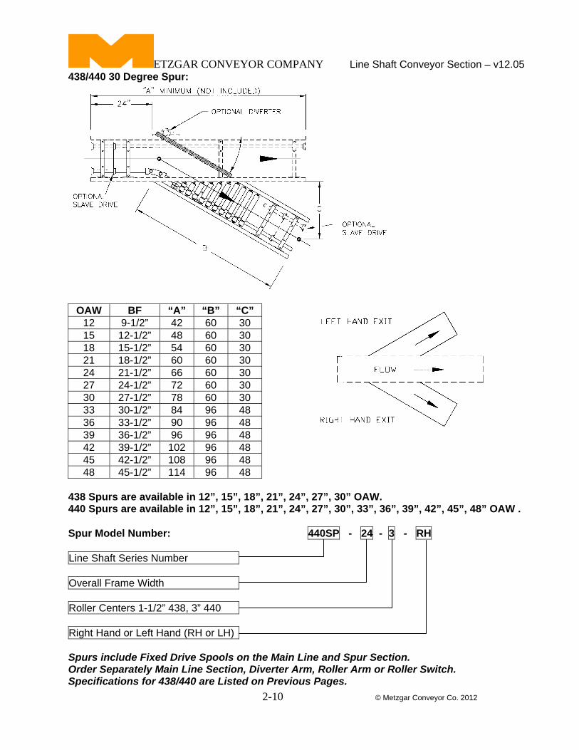
438/440 30 Degree Spur:
OAW BF “A” “B” “C” 12 9-1/2” 42 60 30 15 12-1/2” 48 60 30 18 15-1/2” 54 60 30 21 18-1/2” 60 60 30 24 21-1/2” 66 60 30 27 24-1/2” 72 60 30 30 27-1/2” 78 60 30 33 30-1/2” 84 96 48 36 33-1/2” 90 96 48 39 36-1/2” 96 96 48 42 39-1/2” 102 96 48 45 42-1/2” 108 96 48 48 45-1/2” 114 96 48
438 Spurs are available in 12”, 15”, 18”, 21”, 24”, 27”, 30” OAW. 440 Spurs are available in 12”, 15”, 18”, 21”, 24”, 27”, 30”, 33”, 36”, 39”, 42”, 45”, 48” OAW . Spur Model Number: 440SP - 24 - 3 - RH
Line Shaft Series Number Overall Frame Width Roller Centers 1-1/2” 438, 3” 440 Right Hand or Left Hand (RH or LH) Spurs include Fixed Drive Spools on the Main Line and Spur Section. Order Separately Main Line Section, Diverter Arm, Roller Arm or Roller Switch. Specifications for 438/440 are Listed on Previous Pages.
ETZGAR CONVEYOR COMPANY Line Shaft Conveyor Section – v12.05
2-11 © Metzgar Conveyor Co. 2012
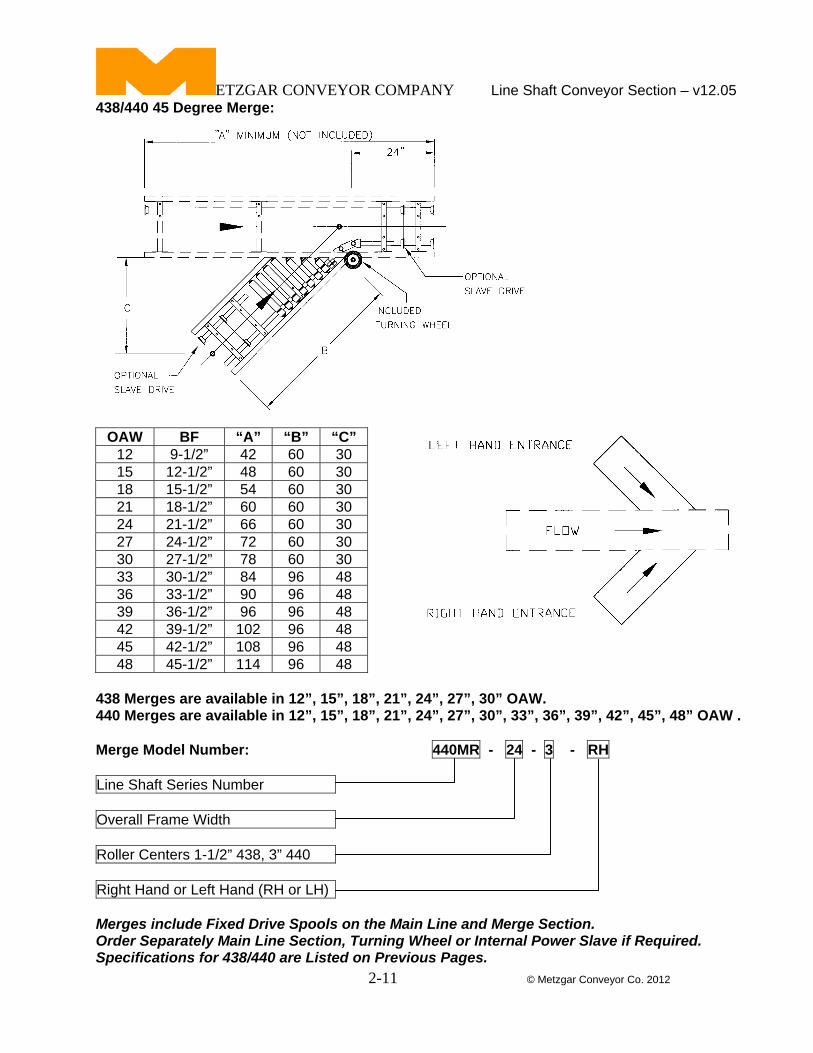
438/440 45 Degree Merge:
OAW BF “A” “B” “C” 12 9-1/2” 42 60 30 15 12-1/2” 48 60 30 18 15-1/2” 54 60 30 21 18-1/2” 60 60 30 24 21-1/2” 66 60 30 27 24-1/2” 72 60 30 30 27-1/2” 78 60 30 33 30-1/2” 84 96 48 36 33-1/2” 90 96 48 39 36-1/2” 96 96 48 42 39-1/2” 102 96 48 45 42-1/2” 108 96 48 48 45-1/2” 114 96 48
438 Merges are available in 12”, 15”, 18”, 21”, 24”, 27”, 30” OAW. 440 Merges are available in 12”, 15”, 18”, 21”, 24”, 27”, 30”, 33”, 36”, 39”, 42”, 45”, 48” OAW . Merge Model Number: 440MR - 24 - 3 - RH
Line Shaft Series Number Overall Frame Width Roller Centers 1-1/2” 438, 3” 440 Right Hand or Left Hand (RH or LH) Merges include Fixed Drive Spools on the Main Line and Merge Section. Order Separately Main Line Section, Turning Wheel or Internal Power Slave if Required. Specifications for 438/440 are Listed on Previous Pages.
ETZGAR CONVEYOR COMPANY Line Shaft Conveyor Section – v12.05
2-12 © Metzgar Conveyor Co. 2012
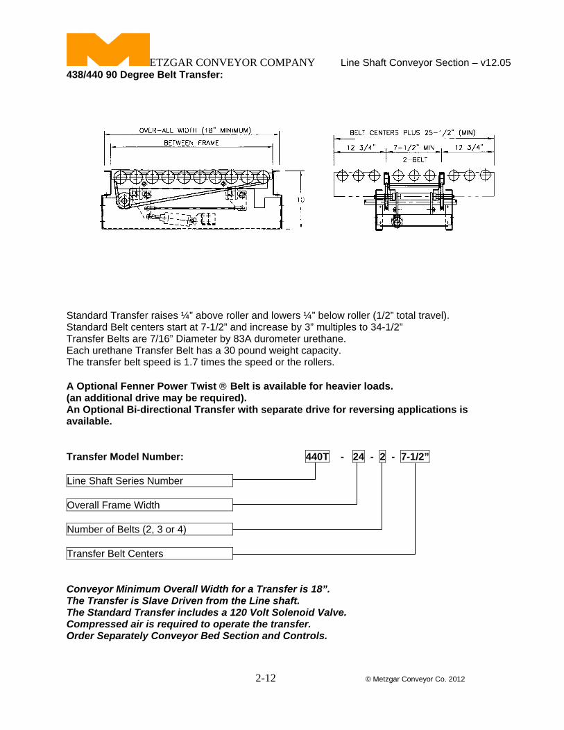
tandard Transfer raises ¼” above roller and lowers ¼” below r er ( 2” tota travel).
Optional Fenner Power Twist ® Belt is available for heavier loads.
ransfer Model Number: 440T - 24 - 2 - 7-1/2”
438/440 90 Degree Belt Transfer:
S oll 1/ l Standard Belt centers start at 7-1/2” and increase by 3” multiples to 34-1/2” Transfer Belts are 7/16” Diameter by 83A durometer urethane. Each urethane Transfer Belt has a 30 pound weight capacity. The transfer belt speed is 1.7 times the speed or the rollers. A(an additional drive may be required). An Optional Bi-directional Transfer with separate drive for reversing applications is available. T
Line Shaft Series Number Overall Frame Width Number of Belts (2, 3 or 4) Transfer Belt Centers Conveyor Minimum Overall Width for a Transfer is 18”.
id Valve.
ls.
The Transfer is Slave Driven from the Line shaft. The Standard Transfer includes a 120 Volt SolenoCompressed air is required to operate the transfer. Order Separately Conveyor Bed Section and Contro
ETZGAR CONVEYOR COMPANY Line Shaft Conveyor Section – v12.05
2-13 © Metzgar Conveyor Co. 2012
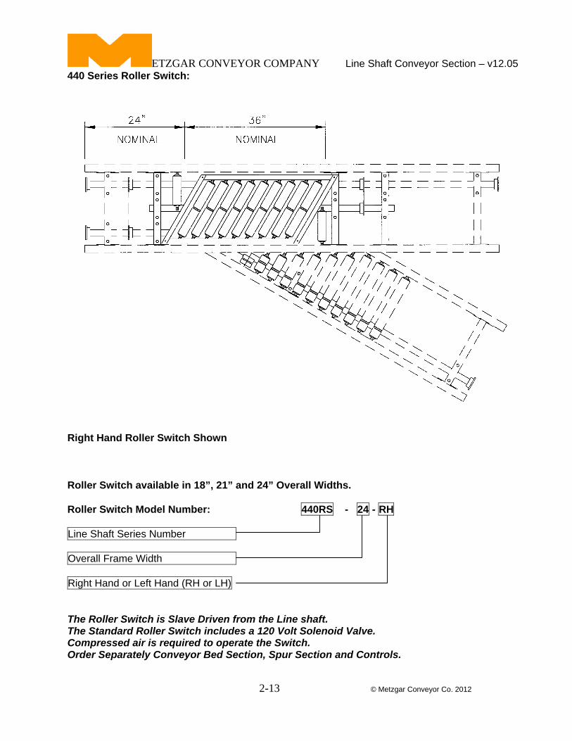
440 Series Roller Switch:
Right Hand Roller Switch Shown Roller Switch available in 18”, 21” and 24” Overall Widths. Roller Switch Model Number: 440RS - 24 - RH
Line Shaft Series Number Overall Frame Width Right Hand or Left Hand (RH or LH) The Roller Switch is Slave Driven from the Line shaft. The Standard Roller Switch includes a 120 Volt Solenoid Valve. Compressed air is required to operate the Switch. Order Separately Conveyor Bed Section, Spur Section and Controls.
ETZGAR CONVEYOR COMPANY Line Shaft Conveyor Section – v12.05
2-14 © Metzgar Conveyor Co. 2012
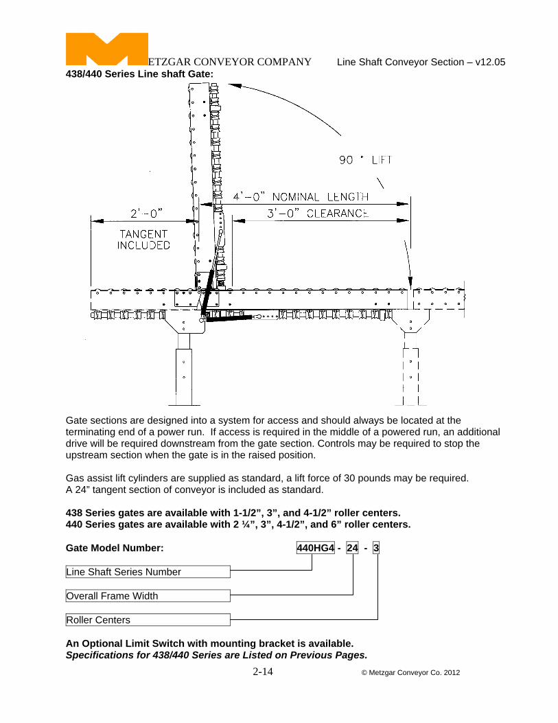
438/440 Series Line shaft Gate:
Gate sections are designed into a system for access and should always be located at the terminating end of a power run. If access is required in the middle of a powered run, an additional drive will be required downstream from the gate section. Controls may be required to stop the upstream section when the gate is in the raised position. Gas assist lift cylinders are supplied as standard, a lift force of 30 pounds may be required. A 24” tangent section of conveyor is included as standard. 438 Series gates are available with 1-1/2”, 3”, and 4-1/2” roller centers. 440 Series gates are available with 2 ¼”, 3”, 4-1/2”, and 6” roller centers. Gate Model Number: 440HG4 - 24 - 3
Line Shaft Series Number Overall Frame Width Roller Centers An Optional Limit Switch with mounting bracket is available. Specifications for 438/440 Series are Listed on Previous Pages.
ETZGAR CONVEYOR COMPANY Line Shaft Conveyor Section – v12.05
2-15 © Metzgar Conveyor Co. 2012
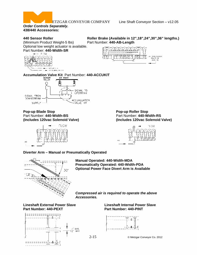
Order Controls Separately. 438/440 Accessories: 440 Sensor Roller Roller Brake (Available in 12”,18”,24”,30”,36” lengths.) (Minimum Product Weight-5 lbs) Part Number: 440-AB-Length Optional low weight actuator is available. Part Number: 440-Width-SR
Accumulation Valve Kit Part Number: 440-ACCUKIT Pop-up Blade Stop Pop-up Roller Stop Part Number: 440-Width-BS Part Number: 440-Width-RS (Includes 120vac Solenoid Valve) (Includes 120vac Solenoid Valve)
Diverter Arm – Manual or Pneumatically Operated Manual Operated: 440-Width-MDA Pneumatically Operated: 440-Width-PDA Optional Power Face Divert Arm is Available Compressed air is required to operate the above Accessories.
Lineshaft External Power Slave Lineshaft Internal Power Slave Part Number: 440-PEXT Part Number: 440-PINT
ETZGAR CONVEYOR COMPANY Line Shaft Conveyor Section – v12.05
2-16 © Metzgar Conveyor Co. 2012
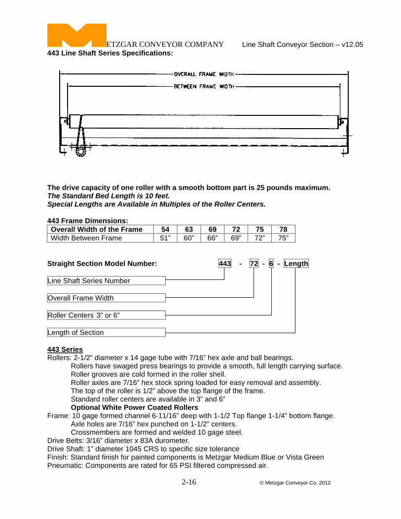
443 Line Shaft Series Specifications:
The drive capacity of one roller with a smooth bottom part is 25 pounds maximum. The Standard Bed Length is 10 feet. Special Lengths are Available in Multiples of the Roller Centers. 443 Frame Dimensions: Overall Width of the Frame 54 63 69 72 75 78 Width Between Frame 51” 60” 66” 69” 72” 75”
Straight Section Model Number: 443 - 72 - 6 - Length
Line Shaft Series Number Overall Frame Width Roller Centers 3” or 6” Length of Section 443 Series Rollers: 2-1/2” diameter x 14 gage tube with 7/16” hex axle and ball bearings. Rollers have swaged press bearings to provide a smooth, full length carrying surface. Roller grooves are cold formed in the roller shell. Roller axles are 7/16” hex stock spring loaded for easy removal and assembly. The top of the roller is 1/2” above the top flange of the frame. Standard roller centers are available in 3” and 6” Optional White Power Coated Rollers Frame: 10 gage formed channel 6-11/16” deep with 1-1/2 Top flange 1-1/4” bottom flange. Axle holes are 7/16” hex punched on 1-1/2” centers. Crossmembers are formed and welded 10 gage steel. Drive Belts: 3/16” diameter x 83A durometer. Drive Shaft: 1” diameter 1045 CRS to specific size tolerance Finish: Standard finish for painted components is Metzgar Medium Blue or Vista Green Pneumatic: Components are rated for 65 PSI filtered compressed air.
ETZGAR CONVEYOR COMPANY Line Shaft Conveyor Section – v12.05
2-17 © Metzgar Conveyor Co. 2012
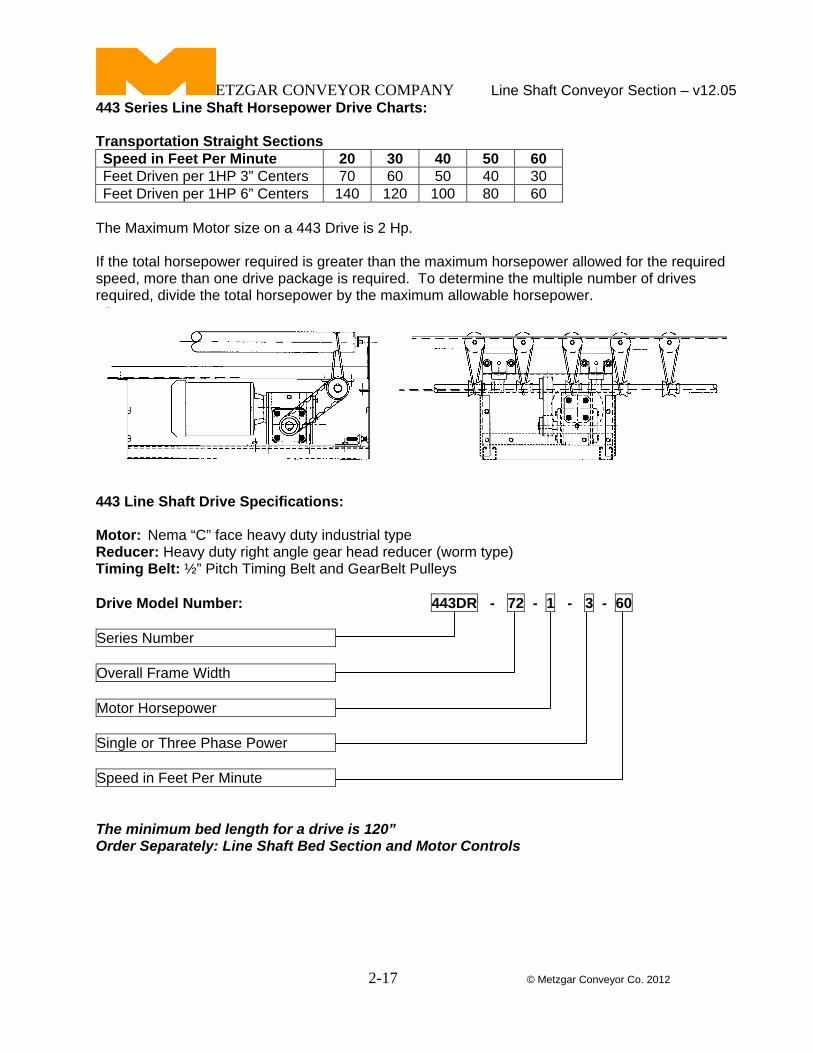
443 Series Line Shaft Horsepower Drive Charts: Transportation Straight Sections Speed in Feet Per Minute 20 30 40 50 60 Feet Driven per 1HP 3” Centers 70 60 50 40 30 Feet Driven per 1HP 6” Centers 140 120 100 80 60
The Maximum Motor size on a 443 Drive is 2 Hp. If the total horsepower required is greater than the maximum horsepower allowed for the required speed, more than one drive package is required. To determine the multiple number of drives required, divide the total horsepower by the maximum allowable horsepower.
443 Line Shaft Drive Specifications: Motor: Nema “C” face heavy duty industrial type Reducer: Heavy duty right angle gear head reducer (worm type) Timing Belt: ½” Pitch Timing Belt and GearBelt Pulleys Drive Model Number: 443DR - 72 - 1 - 3 - 60
Series Number Overall Frame Width Motor Horsepower Single or Three Phase Power Speed in Feet Per Minute The minimum bed length for a drive is 120” Order Separately: Line Shaft Bed Section and Motor Controls
ETZGAR CONVEYOR COMPANY Line Shaft Conveyor Section – v12.05
2-18 © Metzgar Conveyor Co. 2012
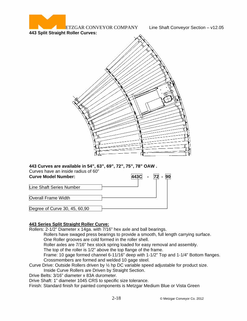
443 Split Straight Roller Curves: 443 Curves are available in 54”, 63”, 69”, 72”, 75”, 78” OAW . Curves have an inside radius of 60” Curve Model Number: 443C - 72 - 90
Line Shaft Series Number Overall Frame Width Degree of Curve 30, 45, 60,90 443 Series Split Straight Roller Curve: Rollers: 2-1/2” Diameter x 14ga. with 7/16” hex axle and ball bearings. Rollers have swaged press bearings to provide a smooth, full length carrying surface. One Roller grooves are cold formed in the roller shell. Roller axles are 7/16” hex stock spring loaded for easy removal and assembly. The top of the roller is 1/2” above the top flange of the frame. Frame: 10 gage formed channel 6-11/16” deep with 1-1/2” Top and 1-1/4” Bottom flanges. Crossmembers are formed and welded 10 gage steel. Curve Drive: Outside Rollers driven by ½ hp DC variable speed adjustable for product size. Inside Curve Rollers are Driven by Straight Section. Drive Belts: 3/16” diameter x 83A durometer. Drive Shaft: 1” diameter 1045 CRS to specific size tolerance. Finish: Standard finish for painted components is Metzgar Medium Blue or Vista Green
ETZGAR CONVEYOR COMPANY Line Shaft Conveyor Section – v12.05
2-19 © Metzgar Conveyor Co. 2012
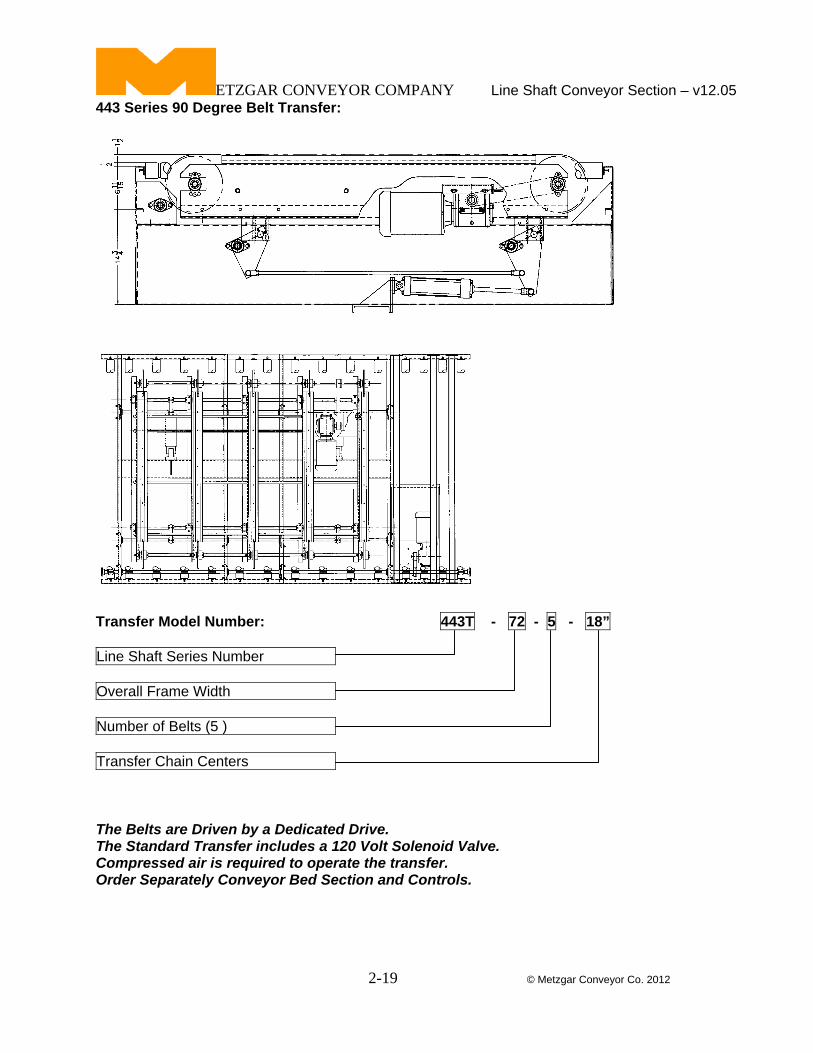
443 Series 90 Degree Belt Transfer:
Standard Belt centers are 18” Each Transfer Chain has a ???? pound weight capacity. Transfer Model Number: 443T - 72 - 5 - 18”
Line Shaft Series Number Overall Frame Width Number of Belts (5 ) Transfer Chain Centers The Belts are Driven by a Dedicated Drive. The Standard Transfer includes a 120 Volt Solenoid Valve. Compressed air is required to operate the transfer. Order Separately Conveyor Bed Section and Controls.
ETZGAR CONVEYOR COMPANY Line Shaft Conveyor Section – v12.05
2-20 © Metzgar Conveyor Co. 2012
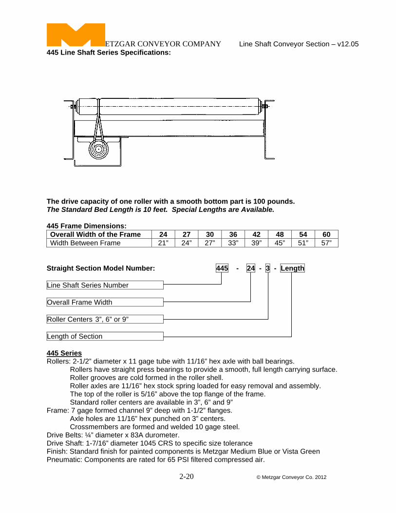
445 Line Shaft Series Specifications:
The drive capacity of one roller with a smooth bottom part is 100 pounds. The Standard Bed Length is 10 feet. Special Lengths are Available. 445 Frame Dimensions: Overall Width of the Frame 24 27 30 36 42 48 54 60 Width Between Frame 21” 24” 27” 33” 39” 45” 51” 57”
Straight Section Model Number: 445 - 24 - 3 - Length
Line Shaft Series Number Overall Frame Width Roller Centers 3”, 6” or 9” Length of Section 445 Series Rollers: 2-1/2” diameter x 11 gage tube with 11/16” hex axle with ball bearings. Rollers have straight press bearings to provide a smooth, full length carrying surface. Roller grooves are cold formed in the roller shell. Roller axles are 11/16” hex stock spring loaded for easy removal and assembly. The top of the roller is 5/16” above the top flange of the frame. Standard roller centers are available in 3”, 6” and 9” Frame: 7 gage formed channel 9” deep with 1-1/2” flanges. Axle holes are 11/16” hex punched on 3” centers. Crossmembers are formed and welded 10 gage steel. Drive Belts: ¼” diameter x 83A durometer. Drive Shaft: 1-7/16” diameter 1045 CRS to specific size tolerance Finish: Standard finish for painted components is Metzgar Medium Blue or Vista Green Pneumatic: Components are rated for 65 PSI filtered compressed air.
ETZGAR CONVEYOR COMPANY Line Shaft Conveyor Section – v12.05
2-21 © Metzgar Conveyor Co. 2012
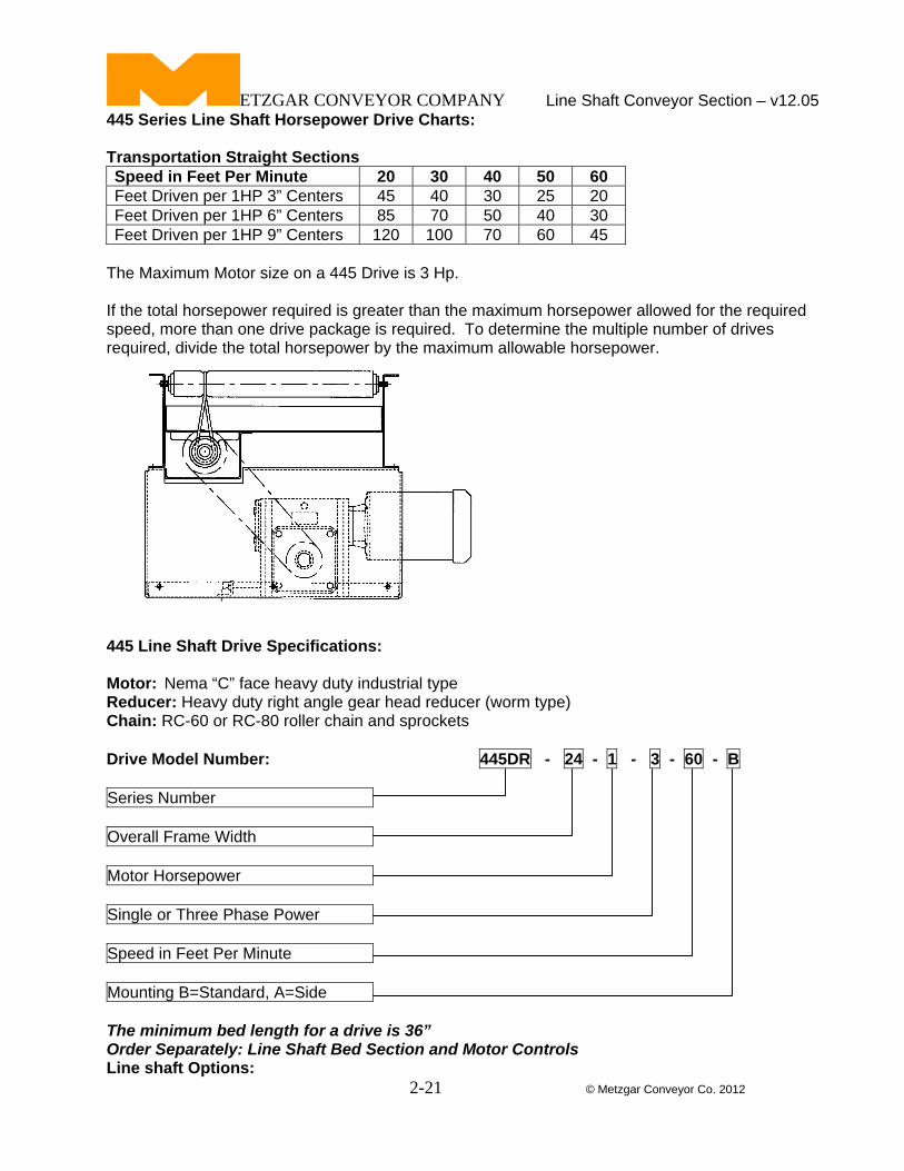
445 Series Line Shaft Horsepower Drive Charts: Transportation Straight Sections Speed in Feet Per Minute 20 30 40 50 60 Feet Driven per 1HP 3” Centers 45 40 30 25 20 Feet Driven per 1HP 6” Centers 85 70 50 40 30 Feet Driven per 1HP 9” Centers 120 100 70 60 45
The Maximum Motor size on a 445 Drive is 3 Hp. If the total horsepower required is greater than the maximum horsepower allowed for the required speed, more than one drive package is required. To determine the multiple number of drives required, divide the total horsepower by the maximum allowable horsepower.
445 Line Shaft Drive Specifications: Motor: Nema “C” face heavy duty industrial type Reducer: Heavy duty right angle gear head reducer (worm type) Chain: RC-60 or RC-80 roller chain and sprockets Drive Model Number: 445DR - 24 - 1 - 3 - 60 - B
Series Number Overall Frame Width Motor Horsepower Single or Three Phase Power Speed in Feet Per Minute Mounting B=Standard, A=Side The minimum bed length for a drive is 36” Order Separately: Line Shaft Bed Section and Motor Controls Line shaft Options:
ETZGAR CONVEYOR COMPANY Line Shaft Conveyor Section – v12.05
2-22 © Metzgar Conveyor Co. 2012
Frame Options: Butt Bolt Frame Connectors 9” Deep Frames Special Widths to match an Existing Conveyor Special Degree Curves Special Paint Colors Powder Coated Frames Bright Zinc Plating on Frames Fixed Drive Spools for Positive Drive Spare Drive Belts assembled on shaft Universal Joint Couplings Drive Timing Belt Components Power Slave Timing Belt Components Taper Lock Sprocket Hubs Full Width End Covers Full Width End Cover Stops Perforated Line shaft Guard Roller Options: Special Roller Lengths Plastisol Coating on Rollers Urethane Coating on Rollers Powder Coated Rollers Bright Zinc Plating on Rollers Semi Precision Roller Bearings ABEC-1 Precision Roller Bearings
ETZGAR CONVEYOR COMPANY Line Shaft Conveyor Section – v12.05
2-23 © Metzgar Conveyor Co. 2012
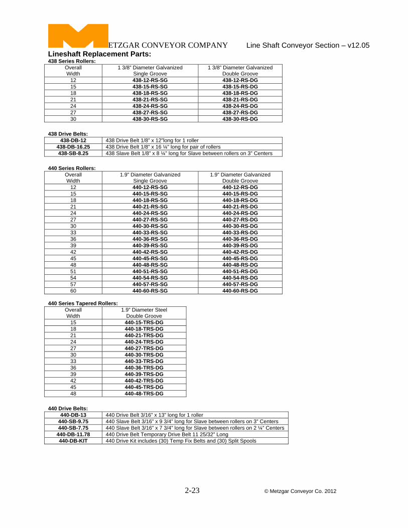
Lineshaft Replacement Parts: 438 Series Rollers:
Overall Width
1 3/8” Diameter Galvanized Single Groove
1 3/8” Diameter Galvanized Double Groove
12 438-12-RS-SG 438-12-RS-DG 15 438-15-RS-SG 438-15-RS-DG 18 438-18-RS-SG 438-18-RS-DG 21 438-21-RS-SG 438-21-RS-DG 24 438-24-RS-SG 438-24-RS-DG 27 438-27-RS-SG 438-27-RS-DG 30 438-30-RS-SG 438-30-RS-DG
438 Drive Belts:
438-DB-12 438 Drive Belt 1/8” x 12”long for 1 roller 438-DB-16.25 438 Drive Belt 1/8” x 16 ¼” long for pair of rollers 438-SB-8.25 438 Slave Belt 1/8” x 8 ¼” long for Slave between rollers on 3” Centers
440 Series Rollers:
Overall Width
1.9” Diameter Galvanized Single Groove
1.9” Diameter Galvanized Double Groove
12 440-12-RS-SG 440-12-RS-DG 15 440-15-RS-SG 440-15-RS-DG 18 440-18-RS-SG 440-18-RS-DG 21 440-21-RS-SG 440-21-RS-DG 24 440-24-RS-SG 440-24-RS-DG 27 440-27-RS-SG 440-27-RS-DG 30 440-30-RS-SG 440-30-RS-DG 33 440-33-RS-SG 440-33-RS-DG 36 440-36-RS-SG 440-36-RS-DG 39 440-39-RS-SG 440-39-RS-DG 42 440-42-RS-SG 440-42-RS-DG 45 440-45-RS-SG 440-45-RS-DG 48 440-48-RS-SG 440-48-RS-DG 51 440-51-RS-SG 440-51-RS-DG 54 440-54-RS-SG 440-54-RS-DG 57 440-57-RS-SG 440-57-RS-DG 60 440-60-RS-SG 440-60-RS-DG
440 Series Tapered Rollers:
Overall Width
1.9” Diameter Steel Double Groove
15 440-15-TRS-DG 18 440-18-TRS-DG 21 440-21-TRS-DG 24 440-24-TRS-DG 27 440-27-TRS-DG 30 440-30-TRS-DG 33 440-33-TRS-DG 36 440-36-TRS-DG 39 440-39-TRS-DG 42 440-42-TRS-DG 45 440-45-TRS-DG 48 440-48-TRS-DG
440 Drive Belts:
440-DB-13 440 Drive Belt 3/16” x 13” long for 1 roller 440-SB-9.75 440 Slave Belt 3/16” x 9 3/4” long for Slave between rollers on 3” Centers 440-SB-7.75 440 Slave Belt 3/16” x 7 3/4” long for Slave between rollers on 2 ¼” Centers
440-DB-11.78 440 Drive Belt Temporary Drive Belt 11 25/32” Long 440-DB-KIT 440 Drive Kit includes (30) Temp Fix Belts and (30) Split Spools
ETZGAR CONVEYOR COMPANY Line Shaft Conveyor Section – v12.05
2-24 © Metzgar Conveyor Co. 2012
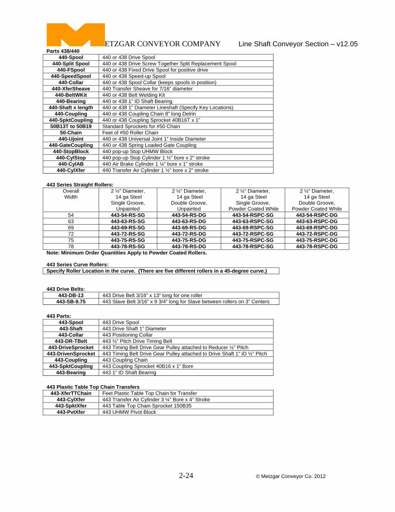
Parts 438/440 440-Spool 440 or 438 Drive Spool
440-Split Spool 440 or 438 Drive Screw Together Split Replacement Spool 440-FSpool 440 or 438 Fixed Drive Spool for positive drive
440-SpeedSpool 440 or 438 Speed-up Spool 440-Collar 440 or 438 Spool Collar (keeps spools in position)
440-XferSheave 440 Transfer Sheave for 7/16” diameter 440-BeltWKit 440 or 438 Belt Welding Kit 440-Bearing 440 or 438 1” ID Shaft Bearing
440-Shaft x length 440 or 438 1” Diameter Lineshaft (Specify Key Locations) 440-Coupling 440 or 438 Coupling Chain 8” long Delrin
440-SpktCoupling 440 or 438 Coupling Sprocket 40B16T x 1” 50B13T to 50B19 Standard Sprockets for #50 Chain
50-Chain Feet of #50 Roller Chain 440-Ujoint 440 or 438 Universal Joint 1” Inside Diameter
440-GateCoupling 440 or 438 Spring Loaded Gate Coupling 440-StopBlock 440 pop-up Stop UHMW Block
440-CylStop 440 pop-up Stop Cylinder 1 ½” bore x 2” stroke 440-CylAB 440 Air Brake Cylinder 1 ¼” bore x 1” stroke 440-CylXfer 440 Transfer Air Cylinder 1 ½” bore x 2” stroke
443 Series Straight Rollers:
Overall Width
2 ½” Diameter, 14 ga Steel
Single Groove, Unpainted
2 ½” Diameter, 14 ga Steel
Double Groove, Unpainted
2 ½” Diameter, 14 ga Steel
Single Groove, Powder Coated White
2 ½” Diameter, 14 ga Steel
Double Groove, Powder Coated White
54 443-54-RS-SG 443-54-RS-DG 443-54-RSPC-SG 443-54-RSPC-DG 63 443-63-RS-SG 443-63-RS-DG 443-63-RSPC-SG 443-63-RSPC-DG 69 443-69-RS-SG 443-69-RS-DG 443-69-RSPC-SG 443-69-RSPC-DG 72 443-72-RS-SG 443-72-RS-DG 443-72-RSPC-SG 443-72-RSPC-DG 75 443-75-RS-SG 443-75-RS-DG 443-75-RSPC-SG 443-75-RSPC-DG 78 443-78-RS-SG 443-78-RS-DG 443-78-RSPC-SG 443-78-RSPC-DG
Note: Minimum Order Quantities Apply to Powder Coated Rollers. 443 Series Curve Rollers: Specify Roller Location in the curve. (There are five different rollers in a 45-degree curve.) 443 Drive Belts:
443-DB-13 443 Drive Belt 3/16” x 13“ long for one roller 443-SB-9.75 443 Slave Belt 3/16” x 9 3/4” long for Slave between rollers on 3” Centers
443 Parts:
443-Spool 443 Drive Spool 443-Shaft 443 Drive Shaft 1” Diameter 443-Collar 443 Positioning Collar
443-DR-TBelt 443 ½” Pitch Drive Timing Belt 443-DriveSprocket 443 Timing Belt Drive Gear Pulley attached to Reducer ½” Pitch
443-DrivenSprocket 443 Timing Belt Drive Gear Pulley attached to Drive Shaft 1” ID ½” Pitch 443-Coupling 443 Coupling Chain
443-SpktCoupling 443 Coupling Sprocket 40B16 x 1” Bore 443-Bearing 443 1” ID Shaft Bearing
443 Plastic Table Top Chain Transfers
443-XferTTChain Feet Plastic Table Top Chain for Transfer 443-CylXfer 443 Transfer Air Cylinder 3 ¼” Bore x 4” Stroke
443-SpktXfer 443 Table Top Chain Sprocket 150B35 443-PvtXfer 443 UHMW Pivot Block
ETZGAR CONVEYOR COMPANY Line Shaft Conveyor Section – v12.05
2-25 © Metzgar Conveyor Co. 2012
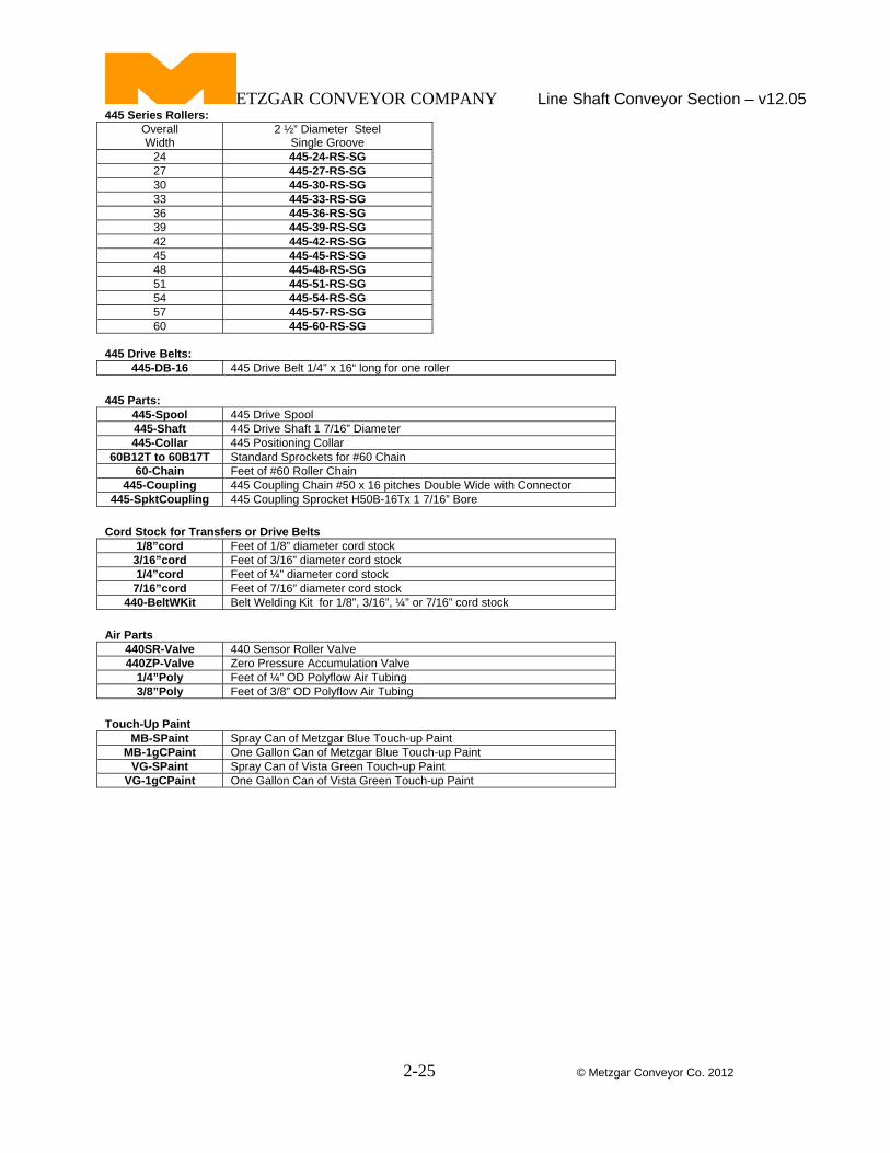
445 Series Rollers: Overall Width
2 ½” Diameter Steel Single Groove
24 445-24-RS-SG 27 445-27-RS-SG 30 445-30-RS-SG 33 445-33-RS-SG 36 445-36-RS-SG 39 445-39-RS-SG 42 445-42-RS-SG 45 445-45-RS-SG 48 445-48-RS-SG 51 445-51-RS-SG 54 445-54-RS-SG 57 445-57-RS-SG 60 445-60-RS-SG
445 Drive Belts:
445-DB-16 445 Drive Belt 1/4” x 16“ long for one roller 445 Parts:
445-Spool 445 Drive Spool 445-Shaft 445 Drive Shaft 1 7/16” Diameter 445-Collar 445 Positioning Collar
60B12T to 60B17T Standard Sprockets for #60 Chain 60-Chain Feet of #60 Roller Chain
445-Coupling 445 Coupling Chain #50 x 16 pitches Double Wide with Connector 445-SpktCoupling 445 Coupling Sprocket H50B-16Tx 1 7/16” Bore
Cord Stock for Transfers or Drive Belts
1/8”cord Feet of 1/8” diameter cord stock 3/16”cord Feet of 3/16” diameter cord stock 1/4”cord Feet of ¼” diameter cord stock
7/16”cord Feet of 7/16” diameter cord stock 440-BeltWKit Belt Welding Kit for 1/8”, 3/16”, ¼” or 7/16” cord stock
Air Parts
440SR-Valve 440 Sensor Roller Valve 440ZP-Valve Zero Pressure Accumulation Valve
1/4”Poly Feet of ¼” OD Polyflow Air Tubing 3/8”Poly Feet of 3/8” OD Polyflow Air Tubing
Touch-Up Paint
MB-SPaint Spray Can of Metzgar Blue Touch-up Paint MB-1gCPaint One Gallon Can of Metzgar Blue Touch-up Paint
VG-SPaint Spray Can of Vista Green Touch-up Paint VG-1gCPaint One Gallon Can of Vista Green Touch-up Paint
ETZGAR CONVEYOR COMPANY Line Shaft Conveyor Section – v12.05
2-26 © Metzgar Conveyor Co. 2012
Notes: