equipment selection and sizing for sprinkler and drip...
TRANSCRIPT

Equipment Selection and Sizing for Sprinkler and Drip Irrigation
Howard Neibling and Jo Ann Robbins University of Idaho
Figure 1. (left) Portable impact sprinkler with 5/8-inch diameter garden hose supply; (right) buried supply line with pop-up gear-drive heads. Both have about 40-foot wetted radius. Types of sprinklers Two general types of sprinklers used in lawns, gardens, and pastures are impact or gear-drive sprinklers which produce moving streams of water (Figure 1), and spray nozzles (Figure 2), with water discharge at all points in the wetted pattern at all times. Impact or gear-drive sprinklers can accommodate only full or part circle application patterns. Since each sprinkler covers a large area (typically 40 foot head-to-head spacing), they are used on pastures and larger lawn areas. They may be used in a solid set configuration, where sufficient nozzles are installed to cover all parts of the desired area with surface or buried mainline and laterals, or in a set-move configuration where lateral lines are operated and then moved on 12 or 24-hour intervals. Solid set systems cost more to install, but have a low labor requirement and may be automated. Set-move system equipment and installation costs less per acre, but has higher recurring operating labor requirements and cannot be completely automated.
Figure 2. Pop-up half-circle spray heads. Head-to-head spacing is 10 feet.

Specialized spray nozzles have been designed for full and part circle, square pattern, or rectangular strips. Because typical head-to-head spacing is less than 15 feet, these nozzles are well suited to small or odd-shaped areas. Both types of sprinklers can be mounted in surface or pop-up configurations. In general, water application rates are higher for spray nozzles (several inches per hour) than for impact or gear drive (about 0.2 - 0.4 inch per hour). Because the water application rate from spray heads is high, they should be operated for a relatively short period of time during each irrigation event to supply the desired depth of water. For example, if the application rate is 4 inches per hour and the desired irrigation is 1 inch, an irrigation time of 1 inch/(4 inches per hour) gives an irrigation time of 1/4 hour, or 15 minutes. Irrigation time for a gear-drive or impact sprinkler would be much longer. For a 1-inch irrigation at 0.25 inches per hour, the irrigation time would be 4 hours. Because of the large difference in application rate, these two types of sprinklers should not be mixed on one zone. Matching application rate to soil intake rate: One of the most common difficulties with lawn sprinkler systems is that water is applied at a rate higher than the soil can absorb it. The result is that water intended for one spot does not move into the soil at that point, but flows to a lower area and contributes excess water at that point, resulting in dry and wet spots. Yellow wet spots indicate that nitrogen has been leached below the plant roots and is no longer available for plant use. Water infiltration rate (the rate that water will move into the soil) starts out high at the beginning of irrigation and drops off to a nearly constant rate that can be sustained for a long period of time (Figure 3).
Figure 3. Typical reduction in soil infiltration rate with time from field measurements on a Dundee sandy loam. (Source: Kechrid, M.S. Shape and Compaction Effects on Furrow Irrigation Performance. M.S. Thesis. Department of Agricultural Engineering, University of Missouri-Columbia 1991.) Sprinkler equipment in pastures: Both above-ground and buried lateral systems can be used for irrigating pastures. The lowest-cost, highest labor requirement system is the portable big gun system shown in Figure 4. Spacing between sets is usually “head-to-head” to achieve proper sprinkler overlap and reasonable application uniformity. This means that location of the gun in
Time Since Initiation of Water Application, minutes

future sets will be at the edge of the wetted pattern of the current set. Set spacings can vary from 50 feet to over 100 feet depending on gun pressure, orifice diameter, and unit design. Proper mainline and supply hose size is critical to assure adequate pressure at the gun.
Figure 4. (left) Portable “big gun” sprinkler for pasture use (available from Farmore Irrigation, Jerome); (right) water supply risers in pasture. Risers outside the fence or in the fence line are less likely to be damaged by livestock or machinery traffic. Minimum hose size for proper operation is 1.5 inch. Note the poor pattern from this sprinkler, which is supplied with a ¾ inch diameter garden hose. Solid-set systems with above-ground main and laterals are shown in Figure 5 for aluminum equipment commonly used in agricultural fields, and for a polyethylene pipe main and lateral system. The aluminum system is readily available, and many times used equipment can be purchased. However, damage from animal traffic and from scratching of risers can be a significant problem. The arrangement shown in the right half of Figure 5 nearly eliminates these problems. The white PVC pipe around the riser tends to protect it from trampling and the shorter riser height prevents scratching.
Figure 5. (left) Solid-set sprinkler lines for irrigation of horse pasture; (right) Semi-permanent solid-set sprinkler heads connected by plastic tubing with laterals connected to mainline by quick-couple connectors.

Equipment shown in Figures 6 and 7 uses impact sprinklers for water distribution. A newer sprinkler design shown in Figure 8 uses another method of rotating the spray pattern. The orange shield shown in sprinklers along the fence in Figure 8 can be quickly attached, and turns a full-circle sprinkler into a half-circle sprinkler by intercepting and re-directing the spray for 1/2 of the sprinkler rotation. This arrangement works well along roads or property lines to prevent spray into areas that need to remain dry. The pattern of the sprinkler jet is more compact than that of a standard impact sprinkler and tends to be affected less by wind.
Figure 6. (left) Solid-set sprinklers with buried main and submains. Sprinklers on protected risers with discharge of 50 gpm each. (right) Solid-set sprinklers with buried main and submains, “big guns” with 175 foot spacing, and 100 gpm discharge per gun.
Figure 7. (left) Post-mounted impact sprinklers to irrigate a line of trees; (right) drip tubing loop around dripline to augment sprinkler. The solid-set big guns shown in Figure 6 are securely mounted in concrete-filled PVC pipes and supplied by buried mainline. The system on the left features both fence-mounted and pasture locations for the big guns. The system is controlled by a manual valve shown in the fence line. System pressure is about 70 psi (pounds per square inch) and the nozzles are significantly smaller than those shown in the right half of the figure. The system shown on the right has large guns that cover about a 175 foot wetted diameter (therefore, about a 175 foot spacing between risers). This system is automatically controlled by an electronic timer. In all big gun systems,

adequate pressure is essential for success. If sprinkler manufacturer pressure requirements cannot be met, either a booster pump should be added or another type of system installed. Trees and foundation plantings: Two arrangements for watering trees are shown in Figure 8. The fence-mounted set of impact sprinklers shown on the left is controlled by an electronic timer and is a good arrangement for using pressurized canal water containing some small debris. These sprinklers have sufficient nozzle size to pass the debris not removed by the main system screen. The drip tubing with emitters shown on the right is a more efficient method of applying water, but requires very clean, or well-filtered water to avoid plugging of the drip emitters.
Figure 8. (left) Nelson R2000 “windfighter” nozzle; (right) Nelson R2000 sprinklers in a solid-set arrangement with buried main and submains and risers protected by PVC pipe. Drip irrigation, either with in-line emitters as shown in Figure 9 (left) or drip tubing with punch-in emitters (Figure 9 right), is an effective method for applying water in small areas without spray drift onto the home or other structures. However, canal water must be well filtered to avoid emitter plugging. Well or municipal water can be used successfully with drip irrigation with little or no filtration.
Figure 9. (left) In-line drip emitters on adjacent lines to water a flower bed; (right) irrigation of rose bush using drip tubing with punch-in emitter. Note tensiometer soil moisture sensing device.
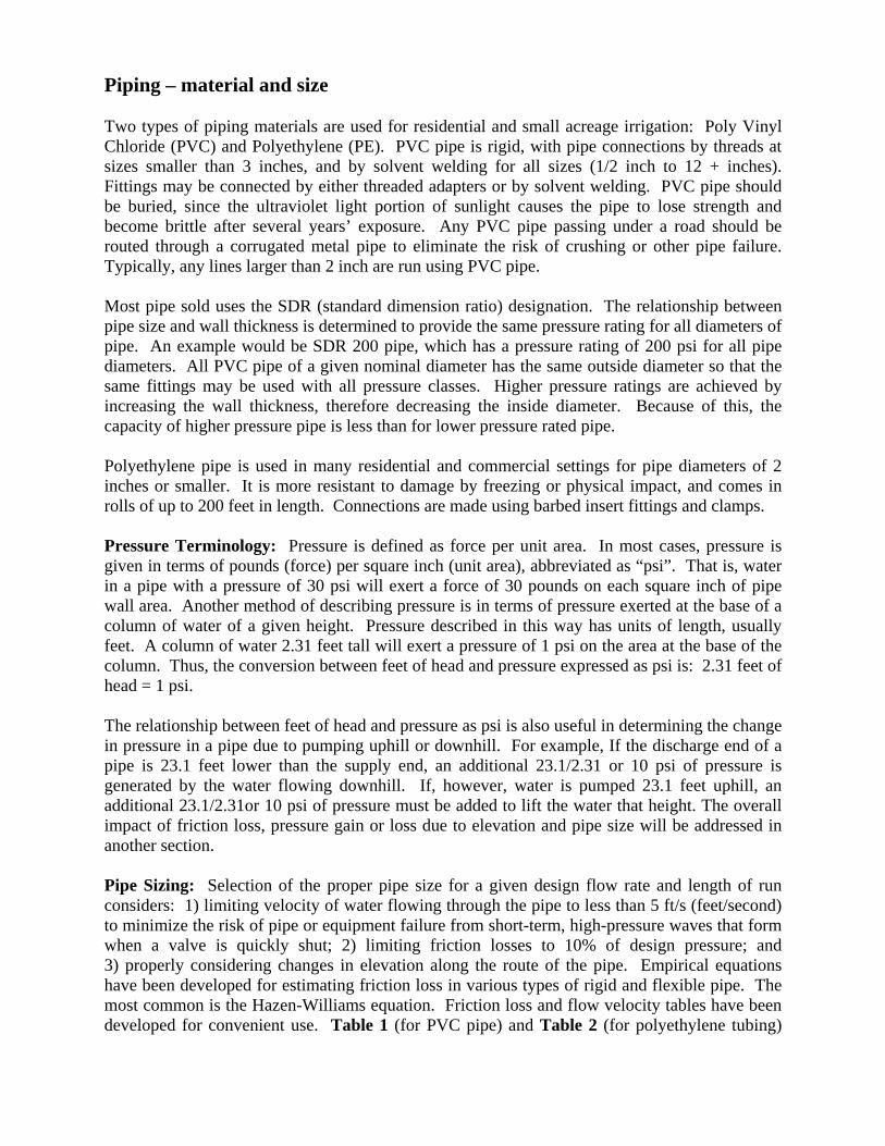
Piping – material and size Two types of piping materials are used for residential and small acreage irrigation: Poly Vinyl Chloride (PVC) and Polyethylene (PE). PVC pipe is rigid, with pipe connections by threads at sizes smaller than 3 inches, and by solvent welding for all sizes (1/2 inch to 12 + inches). Fittings may be connected by either threaded adapters or by solvent welding. PVC pipe should be buried, since the ultraviolet light portion of sunlight causes the pipe to lose strength and become brittle after several years’ exposure. Any PVC pipe passing under a road should be routed through a corrugated metal pipe to eliminate the risk of crushing or other pipe failure. Typically, any lines larger than 2 inch are run using PVC pipe. Most pipe sold uses the SDR (standard dimension ratio) designation. The relationship between pipe size and wall thickness is determined to provide the same pressure rating for all diameters of pipe. An example would be SDR 200 pipe, which has a pressure rating of 200 psi for all pipe diameters. All PVC pipe of a given nominal diameter has the same outside diameter so that the same fittings may be used with all pressure classes. Higher pressure ratings are achieved by increasing the wall thickness, therefore decreasing the inside diameter. Because of this, the capacity of higher pressure pipe is less than for lower pressure rated pipe. Polyethylene pipe is used in many residential and commercial settings for pipe diameters of 2 inches or smaller. It is more resistant to damage by freezing or physical impact, and comes in rolls of up to 200 feet in length. Connections are made using barbed insert fittings and clamps. Pressure Terminology: Pressure is defined as force per unit area. In most cases, pressure is given in terms of pounds (force) per square inch (unit area), abbreviated as “psi”. That is, water in a pipe with a pressure of 30 psi will exert a force of 30 pounds on each square inch of pipe wall area. Another method of describing pressure is in terms of pressure exerted at the base of a column of water of a given height. Pressure described in this way has units of length, usually feet. A column of water 2.31 feet tall will exert a pressure of 1 psi on the area at the base of the column. Thus, the conversion between feet of head and pressure expressed as psi is: 2.31 feet of head = 1 psi. The relationship between feet of head and pressure as psi is also useful in determining the change in pressure in a pipe due to pumping uphill or downhill. For example, If the discharge end of a pipe is 23.1 feet lower than the supply end, an additional 23.1/2.31 or 10 psi of pressure is generated by the water flowing downhill. If, however, water is pumped 23.1 feet uphill, an additional 23.1/2.31or 10 psi of pressure must be added to lift the water that height. The overall impact of friction loss, pressure gain or loss due to elevation and pipe size will be addressed in another section. Pipe Sizing: Selection of the proper pipe size for a given design flow rate and length of run considers: 1) limiting velocity of water flowing through the pipe to less than 5 ft/s (feet/second) to minimize the risk of pipe or equipment failure from short-term, high-pressure waves that form when a valve is quickly shut; 2) limiting friction losses to 10% of design pressure; and 3) properly considering changes in elevation along the route of the pipe. Empirical equations have been developed for estimating friction loss in various types of rigid and flexible pipe. The most common is the Hazen-Williams equation. Friction loss and flow velocity tables have been developed for convenient use. Table 1 (for PVC pipe) and Table 2 (for polyethylene tubing)

give friction loss in psi per 100 feet of length for sizes typically used on sites of 15 acres or less. Blank table cells represent conditions where water velocity through the pipe exceeds 5 ft/s.
Two methods of determining pipe size are used. The first is the maximum velocity approach, which selects pipe size to limit velocity in any segment to less than 5 ft/s. The second, which provides better uniformity, is the friction factor approach. This method limits friction loss in any segment to a pre-determined value. The general approach for pipe sizing would be to: Step 1) determine the piping path from the pump to the most distant (or highest) sprinkler; Step 2) determine pipe length and flow in each segment of that path, with flow based on sprinkler flow rate and the number of sprinklers running at one time; Step 3) determine the “friction factor” as
L
pPFf
where, (equation 1)
Ff = friction factor (no units) P = system pressure at farthest or highest sprinkler psi
P = percent variation in pressure between source and most distant (or critical) sprinkler head expressed as a decimal (e.g. 10% = 0.10). This should be no more than 10%.
L = length in hundreds of feet over which the allowable pressure loss is measured
Step 4) from a friction loss table, select pipe sizes that are equal or less than that factor for each segment of the critical flow path; Step 5) check to see that velocity is < 5 ft/s in all segments. Example #1: The allowable pressure drop from the pump to the most distant sprinkler is 10% (0.10 as a decimal). Pressure at the pump is 50 psi, and the combined length of mainline (140 feet) and lateral (160 feet) is 300 feet. Flow from the mainline supplies 2 moveable laterals at one time. The moveable laterals each supply 4 sprinklers with flow rates of 5 gpm. What size pipe should be used in the mainline? Step 1: piping path to the critical sprinkler is 300 feet (given in this case) Step 2: each lateral is 160 feet long and has a flow at the supply end of 4*5 gpm or 20 gpm. The mainline is given as 140 feet with a flow of 2*20 gpm or 40 gpm.
Step 3: The friction factor is: L
pPFf
. Since L must be expressed in hundreds of feet we
divide 300 feet by 100 to get 3.0 hundred feet.
ftpsifeethundred
psiFf 100/67.10.3
1.050
Step 4: From Table 1, the smallest pipe size with friction loss less than 1.67 psi/100 ft for a 40 gpm flow is 2 inch which has a friction loss of 0.95 psi/100 ft. Pipe sizing and friction loss in the lateral will be discussed next. Step 5: In Table 1, cells with velocity > 5 ft/s have been left blank so the velocity is not excessive.
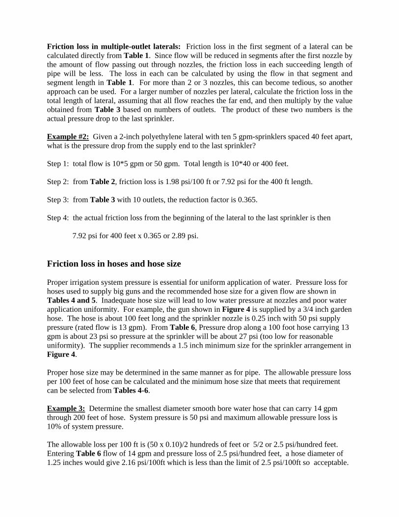
Friction loss in multiple-outlet laterals: Friction loss in the first segment of a lateral can be calculated directly from Table 1. Since flow will be reduced in segments after the first nozzle by the amount of flow passing out through nozzles, the friction loss in each succeeding length of pipe will be less. The loss in each can be calculated by using the flow in that segment and segment length in Table 1. For more than 2 or 3 nozzles, this can become tedious, so another approach can be used. For a larger number of nozzles per lateral, calculate the friction loss in the total length of lateral, assuming that all flow reaches the far end, and then multiply by the value obtained from Table 3 based on numbers of outlets. The product of these two numbers is the actual pressure drop to the last sprinkler. Example #2: Given a 2-inch polyethylene lateral with ten 5 gpm-sprinklers spaced 40 feet apart, what is the pressure drop from the supply end to the last sprinkler? Step 1: total flow is 10*5 gpm or 50 gpm. Total length is 10*40 or 400 feet. Step 2: from Table 2, friction loss is 1.98 psi/100 ft or 7.92 psi for the 400 ft length. Step 3: from Table 3 with 10 outlets, the reduction factor is 0.365. Step 4: the actual friction loss from the beginning of the lateral to the last sprinkler is then 7.92 psi for 400 feet x 0.365 or 2.89 psi. Friction loss in hoses and hose size Proper irrigation system pressure is essential for uniform application of water. Pressure loss for hoses used to supply big guns and the recommended hose size for a given flow are shown in Tables 4 and 5. Inadequate hose size will lead to low water pressure at nozzles and poor water application uniformity. For example, the gun shown in Figure 4 is supplied by a 3/4 inch garden hose. The hose is about 100 feet long and the sprinkler nozzle is 0.25 inch with 50 psi supply pressure (rated flow is 13 gpm). From Table 6, Pressure drop along a 100 foot hose carrying 13 gpm is about 23 psi so pressure at the sprinkler will be about 27 psi (too low for reasonable uniformity). The supplier recommends a 1.5 inch minimum size for the sprinkler arrangement in Figure 4. Proper hose size may be determined in the same manner as for pipe. The allowable pressure loss per 100 feet of hose can be calculated and the minimum hose size that meets that requirement can be selected from Tables 4-6. Example 3: Determine the smallest diameter smooth bore water hose that can carry 14 gpm through 200 feet of hose. System pressure is 50 psi and maximum allowable pressure loss is 10% of system pressure. The allowable loss per 100 ft is (50 x 0.10)/2 hundreds of feet or 5/2 or 2.5 psi/hundred feet. Entering Table 6 flow of 14 gpm and pressure loss of 2.5 psi/hundred feet, a hose diameter of 1.25 inches would give 2.16 psi/100ft which is less than the limit of 2.5 psi/100ft so acceptable.

Nozzle Discharge rate Handline wheel line, solid-set: Gross application rate (water applied assuming no evaporation or other losses) from standard brass nozzles spaced 40 feet apart on a line and a 40 foot spacing between lines is given in Table 7. Values for 40 spacing on a line and 50 foot line spacing are given in Table 8. Moveable big guns (Figure 4): Sprinkler discharge and wetted diameter are given for the Senninger 7025 series sprinkler in Table 9. The nozzle size designations are given as 64th of an inch values and also as decimal equivalent. For example, a #16 nozzle is 16/64 or ¼ inch diameter. For other nozzle sizes approximate flow may be determined as:
HDQ 25.19 where: (equation 2) Q = nozzle flow in gpm D = nozzle diameter, inches H = pressure at nozzle expressed as feet of head (e.g. expressed as psi x 2.31) For example, flow from a ¼ inch nozzle at 50 psi would be:
Q = 19.5 x (0.25)(0.25) 31.250x Q = 19.5 x 0.0625 x 10.75 Q = 13.1 gpm Given nozzle discharge, gross application rate for sprinklers arranged on a rectangular grid may then be determined as:
SL
TxQDepthgross
)()(
604.1 where: (equation 3)
Q = flow from one nozzle, gpm T = run time in minutes L = spacing between sprinklers on a line, feet S = spacing between lines, feet
Net sprinkler application rate The net application rate (water than can be used to meet plant needs) is then:
AE
DepthDepth gross
net where: (equation 4)
netDepth = depth of water applied that is usable by plants (total applied – losses), inches

grossDepth = total depth of water applied, inches (from Tables 7 or 8, or the above
equation)
AE = application efficiency, expressed as a decimal (typical value is 70%, expressed as 0.70)
Example 4: What is the net application depth for sprinklers using 1/8 inch (0.125 inch) brass nozzles with 40 foot spacing between nozzles on a line and 50 foot spacing between lines? System pressure is 60 psi, the system is run for 2 hours, and application efficiency is 70%. From Table 8, gross application rate is 0.17 inch/hour. For 2 hours this would be 0.17 inch/hour x 2 hours or 0.34 inches. The net depth would be the gross depth x application efficiency or:
netDepth = 0.34 inches x 0.70, or 0.24 inches.
This can also be determined by calculation as:
HDQ 25.19 , Q = 19.5 x (0.125) x (0.125) x 31.260x , Q = 3.6 gpm
SL
TxQDepthgross
)()(
604.1 , 5040
min1206.3604.1
grossDepth , grossDepth = 0.35 inches
AEDepthDepth grossnet , 70.035.0 inchesDepthnet , netDepth = 0.24 inches
This approach can also be used to determine net application for solid set or moveable big gun systems. In equation 4, Q will be the flow for one big gun, in gpm. Typically the spacing (both L and S in the equation above) is equal to ½ of the wetted diameter unless specified differently by the manufacturer. Pump installations On a subdivision scale, a pumping plant installation similar to that shown in Figure 10 may be used. To adequately meet variation in system demand without pressure variation, a multiple-pump system with a variable frequency drive is the best choice. The system shown in Figure 10 will deliver 10 - 450 gpm at a constant pressure. It has 3 pumps, one of which is equipped with a variable frequency drive. The system is electronically controlled so that if additional flow is needed and one or more pumps are delivering water at full capacity, another pump is turned on to meet the demand. A properly designed system of this type is the best, although more expensive alternative for this type of application.

. Figure 10. (left) Head gate, inlet screening and pump house for multiple-pump subdivision irrigation system. Capacity = 10 to 450 gpm; (right) pump sump and outlet for a two-user pumping system. Capacity = 20 to 40 gpm For one to 3 or 4 users with water from a lateral, the pump arrangement shown in Figure 10 may be used. Flow from the lateral is metered through a head gate and then passes into a standpipe from which it is pumped for use. Table 10 may be used to determine pump size. For other situations, pump size may be calculated using the following procedure: Pump sizing uses the formula:
pE
HQHp
3960
where: (equation 5)
Hp = horsepower to be supplied by motor Q = flow in gallons per minute (gpm) H = total dynamic head in feet 3960 = constant to give horsepower with this set of Q and H units Ep = pump efficiency expressed as %/100 (e.g. 85% would be used as 0.85)
Total dynamic head may be determined as H = (pressure at design point/2.31) + elevation rise between pump and design point + friction loss between pump and design point + intake lift (ft/2.31) + intake and outlet fitting losses (typically 5 psi). Typically, electric-drive pumps for small acreages come in standard motor sizes such as 1, 1.5, 2, 3, and 5 hp. Example 5: Determine the pump size required to pressurize a flow of 30 gpm to supply a single big gun that is located a maximum of 300 feet away. At the most distant set, the land surface is 15 feet higher than at the pump. The water flows through 200 feet of buried class 200 PVC mainline and 100 feet of 1.5 inch hose. Desired pressure at the sprinkler is 50 psi. Lift from the intake water level to the pump centerline is 5 feet and intake and outlet fitting losses are assumed to be 5 psi. Assume a pump efficiency of 80%. Start at the most distant point and work back to the pump.
1) Friction loss in the hose is 3.64 psi/100 ft from Table 6.

2) Friction loss in the mainline is 0.56 psi/100 ft or 1.12 psi for the 200 ft mainline from Table 1.
3) Pressure required when pumping water uphill 15 feet is 15ft/2.31 ft per psi, or 6.5 psi. 4) Pressure required to lift water from the source to the pump centerline is 5 ft/2.31 or 2.2
psi. 5) The pump must generate 2.2 psi (suction lift) + 5 psi (intake and outlet fitting loss) + 6.5
psi (pumping uphill) + 1.1 psi (mainline loss) + 3.64 psi (hose loss) + 50 psi (desired pressure at the last nozzle location). The pump must generate 68.44 psi at a flow of 30 gpm.
6) In many cases, the 68.44 psi required is expressed as a total dynamic head in feet. Convert 68.44 psi to 158 feet of head by multiplying by 2.31 ft head/1 psi.
7) This information may be taken to a pump sales store and the correct pump and motor size selected, or motor horsepower may be calculated directly using equation 5.
pE
HQHp
3960
80.03960
15830
Hp Hp=1.49 horsepower.
In this case, a 1.5 horsepower pump could be selected if the pump design allowed it to supply the desired flow and pressure. This is the minimum size required. In some cases, the next larger size should be selected. The larger size may be required to provide a pump that can easily meet the requirements and give some spare capacity to accommodate pump wear (and loss of efficiency) and increase in friction loss due to increased pipe and hose roughness over time. Table 1. Friction loss in PVC Class 200 IPS plastic pipe, psi/100 ft of length.
Friction loss as psi / 100 feet of pipe length Flow gpm 0.75 1.0 1.25 1.5 2.0 2.5 3.0
5 1.19 0.36 0.12 0.06 0.02 0.01 10 4.31 1.30 0.42 0.22 0.07 0.03 0.01 15 2.77 0.89 0.46 0.16 0.06 0.03 20 1.51 0.78 0.26 0.10 0.04 25 2.29 1.18 0.40 0.16 0.07 30 1.66 0.56 0.22 0.09 40 0.95 0.38 0.14 60 0.80 0.31 70 1.06 0.41 80 1.36 0.52 90 0.65 100 0.79 120 1.11 140
Note: Flow velocity exceeds 5 ft/s for cells with no listed friction loss.

Table 2. Friction loss in Polyethylene (PE) SDR pressure-rated Tube, psi/100 ft of length. (Adapted from the Hunter Technical Companion Guide, Hunter Industries)
Nominal Diameter inches
1/2 3/4 1 1.25 1.5 2 2.5 3 4 6
Inside Diameter inches
0.622 0.824 1.049 1.380 1.610 2.067 2.469 3.068 4.026 6.065
Max. Flow, gpm (5 ft/s limit) 4 8 14 22 30 50 70 110 190 450
Flow, gpm Friction loss, psi/100 ft
1 0.49 0.12 0.04 0.01 0 0 2 1.76 0.45 0.14 0.04 0.02 0.01 3 3.73 0.95 0.29 0.08 0.04 0.01 0 4 6.35 1.62 0.50 0.13 0.06 0.02 0.01 5 2.44 0.76 0.20 0.09 0.03 0.01 0 10 2.73 0.72 0.34 0.10 0.04 0.01 0 15 1.53 0.72 0.22 0.09 0.03 0.01 20 2.59 1.22 0.36 0.15 0.05 0.01 25 1.83 0.55 0.23 0.08 0.02 30 2.59 0.77 0.32 0.11 0.03 0 40 1.31 0.55 0.15 0.05 0.01 50 1.98 0.83 0.29 0.08 0.01 60 1.17 0.41 0.11 0.01 80 0.69 0.18 0.03 100 1.05 0.28 0.04 150 0.59 0.08 200 1.01 0.14 250 0.21 300 0.29 350 0.39 400 0.50 450 0.62

Table 3. Adjusted friction factor for multiple outlets on a lateral (adapted from IA pg 595) Number of sprinkler
heads on lateral Friction factor, F
(for m=1.9) Number of sprinkler
heads on lateral, cont. Friction factor, F
(for m=1.9) 1 1 14 0.358 2 0.512 16 0.357 3 0.434 18 0.355 4 0.405 20 0.354 5 0.390 22 0.353 6 0.381 24 0.352 7 0.375 26 0.351 8 0.370 28 0.351 9 0.367 30 0.350 10 0.365 32 0.350 12 0.361 34 0.350
Table 4. Friction loss in flexible irrigation hose used on traveling gun type sprinkler systems (From: USDA-NRCS National Engineering Handbook, Ch6, Part 652) Nominal hose diameter, inches Flow 2.5 3 3.5 4 4.5 5 Gpm Friction loss, psi/100 feet of hose length 100 1.6 0.7 0.3 150 3.4 1.4 0.8 200 5.6 2.5 1.4 0.6 250 3.6 1.6 0.9 300 5.1 1.8 1.2 0.6 400 2.3 1.5 1.3 500 3.5 2.1 2.0 600 2.9 2.7 1.1 700 3.6 3.1 1.7 800 4.6 2.7 900 3.4 1000 4.2 Table 5. Guidelines for sizing traveling gun type sprinkler hoses. (From: USDA-NRCS National Engineering Handbook, Ch6, Part 652) Flow range, gpm Hose diameter, inches 50 to 150 2.5 150 to 250 3.0 200 to 350 3.5 250 to 500 4.0 500 to 700 4.5 > 700 5.0

Table 6. Friction loss in smooth-bore water hose (Adapted from Watkins, J.A. 1987. Turf Irrigation Manual. Telsco Industries, 5th printing. 363 pp.). Units are psi/100 ft Flow Nominal Hose diameter, inches gpm 1/2 5/8 3/4 1 1.25 1.5 2 3 4 1 1.41 0.477 0.196 0.048 0.016 0.007 0.002 2 5.09 1.72 0.707 0.175 0.059 0.024 0.006 3 10.77 3.64 1.5 0.369 0.125 0.051 0.013 4 18.34 6.19 2.55 0.629 0.212 0.087 0.022 5 27.71 9.36 3.85 0.951 0.321 0.132 0.033 6 38.83 13.11 5.40 1.33 0.450 0.185 0.046 7 51.64 17.44 7.18 1.77 0.598 0.246 0.061 8 66.12 22.32 9.19 2.27 0.766 0.315 0.078 9 82.21 27.76 11.43 2.82 0.952 0.392 0.097 10 99.91 33.73 13.89 3.43 1.16 0.477 0.118 12 47.27 19.47 4.80 1.62 0.668 0.165 14 62.87 25.89 6.39 2.16 0.888 0.219 16 33.15 8.18 2.76 1.14 0.280 18 41.22 10.17 3.43 1.41 0.349 20 50.09 12.35 4.17 1.72 0.424 22 14.74 4.98 2.05 0.506 24 17.31 5.85 2.41 0.594 26 20.07 6.78 2.79 0.689 28 23.02 7.77 3.2 0.790 30 26.16 8.83 3.64 0.897 32 29.48 9.95 4.10 1.01 34 32.97 11.13 4.59 1.13 36 36.65 12.38 5.10 1.26 38 13.68 5.63 1.39 40 15.04 6.19 1.53 0.212 50 22.73 9.36 2.31 0.321 60 13.11 3.23 0.450 0.111 70 17.44 4.30 0.598 0.148 80 22.33 5.51 0.766 0.189 90 6.85 0.952 0.235 100 8.32 1.16 0.285 120 11.66 1.62 0.400 140 15.51 2.16 0.532 160 2.76 0.681 180 3.43 0.847 200 4.17 1.03 250 6.30 1.56 300 8.83 2.18 350 2.90 400 3.71 450 4.61 500 5.61 550 6.69

Table 7. Average gross application rate in inches/hour for 40 x 40 foot nozzle spacing.
Nozzle Diameter, inches Pressure, psi 7/64 1/8 9/64 5/32 11/64 3/16 13/64 7/32 30 0.12 0.15 0.19 0.24 0.29 0.34 0.40 0.46 32 0.12 0.16 0.20 0.24 0.29 0.35 0.41 0.48 34 0.12 0.16 0.20 0.25 0.30 0.36 0.42 0.49 36 0.13 0.17 0.21 0.26 0.31 0.37 0.44 0.51 38 0.13 0.17 0.21 0.27 0.32 0.38 0.45 0.52 40 0.13 0.17 0.22 0.27 0.33 0.39 0.46 0.53 42 0.14 0.18 0.23 0.28 0.34 0.40 0.47 0.55 44 0.14 0.18 0.23 0.29 0.35 0.41 0.48 0.56 46 0.14 0.19 0.24 0.29 0.35 0.42 0.49 0.57 48 0.15 0.19 0.24 0.30 0.36 0.43 0.50 0.58 50 0.15 0.19 0.25 0.30 0.37 0.44 0.51 0.60 52 0.15 0.20 0.25 0.31 0.38 0.45 0.52 0.61 54 0.15 0.20 0.26 0.32 0.38 0.46 0.53 0.62 56 0.16 0.21 0.26 0.32 0.39 0.46 0.54 0.63 58 0.16 0.21 0.27 0.33 0.40 0.47 0.55 0.64 60 0.16 0.21 0.27 0.33 0.40 0.48 0.56 0.65 62 0.17 0.22 0.27 0.34 0.41 0.49 0.57 0.66 64 0.17 0.22 0.28 0.34 0.42 0.50 0.58 0.67 66 0.17 0.22 0.28 0.35 0.42 0.50 0.59 0.69 68 0.17 0.23 0.29 0.35 0.43 0.51 0.60 0.70 70 0.18 0.23 0.29 0.36 0.44 0.52 0.61 0.71

Table 8. Average gross application rate in inches/hour for 40 x 50 foot nozzle spacing.
Nozzle Diameter, inches Pressure, psi 7/64 1/8 9/64 5/32 11/64 3/16 13/64 7/32 30 0.09 0.12 0.15 0.19 0.23 0.27 0.32 0.37 32 0.10 0.12 0.16 0.19 0.24 0.28 0.33 0.38 34 0.10 0.13 0.16 0.2 0.24 0.29 0.34 0.39 36 0.10 0.13 0.17 0.21 0.25 0.30 0.35 0.40 38 0.10 0.14 0.17 0.21 0.26 0.31 0.36 0.42 40 0.11 0.14 0.18 0.22 0.26 0.31 0.37 0.43 42 0.11 0.14 0.18 0.22 0.27 0.32 0.38 0.44 44 0.11 0.15 0.18 0.23 0.28 0.33 0.39 0.45 46 0.11 0.15 0.19 0.23 0.28 0.34 0.39 0.46 48 0.12 0.15 0.19 0.24 0.29 0.34 0.40 0.47 50 0.12 0.16 0.20 0.24 0.29 0.35 0.41 0.48 52 0.12 0.16 0.20 0.25 0.30 0.36 0.42 0.49 54 0.12 0.16 0.20 0.25 0.31 0.36 0.43 0.50 56 0.13 0.16 0.21 0.26 0.31 0.37 0.44 0.51 58 0.13 0.17 0.21 0.26 0.32 0.38 0.44 0.51 60 0.13 0.17 0.22 0.27 0.32 0.38 0.45 0.52 62 0.13 0.17 0.22 0.27 0.33 0.39 0.46 0.53 64 0.13 0.18 0.22 0.28 0.33 0.40 0.47 0.54 66 0.14 0.18 0.23 0.28 0.34 0.40 0.47 0.55 68 0.14 0.18 0.23 0.28 0.34 0.41 0.48 0.56 70 0.14 0.18 0.23 0.29 0.35 0.41 0.49 0.56 Table 9. Nozzle discharge and wetted diameter for nozzle sizes used on Senninger model 7025 impact sprinklers (portable big gun applications).
Nozzle diameter #14 #16 #18 #20 #22 #24 7/32” ¼” 9/32” 5/16” 11/32” 3/8”
0.219” 0.25” 0.281” 0.313” 0.344” 0.375” Nozzle Flow
gpm 9.97 13 16.3 20 24.1 28.4
Wetted diameter
Feet 120 128 135 141 145 148

Table 10. Determination of pump size.
Motor horsepower1
System pressure
Flow, gpm 40 50 60 70 80
5 0.2 0.2 0.3 0.3 0.3
10 0.4 0.4 0.5 0.6 0.7
15 0.5 0.6 0.8 0.9 1.0
20 0.7 0.9 1.0 1.2 1.3
25 0.9 1.1 1.3 1.5 1.6
30 1.1 1.3 1.5 1.7 2.0
40 1.4 1.7 2.0 2.3 2.6
50 1.8 2.2 2.5 2.9 3.3
1 Assumes pump efficiency = 80%, intake lift & friction loss = 10 feet, fitting loss = 5 feet, and mainline friction loss = 5% of design pressure.