engineering services for the next generation nuclear … documents/general...911119 revision 0...
TRANSCRIPT

911119Revision 0
Engineering Services for the Next Generation Nuclear Plant (NGNP) with Hydrogen Production
NGNP IHX and Secondary Heat Transport Loop Alternatives Study
Prepared by General Atomics For the Battelle Energy Alliance, LLC
Subcontract No. 00060845 Uniform Filing Code UFC:8201.3.1.2
GA Project 30283
RELEASED2008/04/23

NGNP IHX and Secondary Heat Transport Loop Alternatives Study 911119/0
iii
LIST OF CONTRIBUTORS
Name Organization
John Bolin General Atomics
Dave Carosella General Atomics
Dale Pfremmer General Atomics
John Saurwein General Atomics
Brian Thurgood BVPA Engineering
Claire Sims Rolls-Royce
John Garibaldi URS-Washington Division
William McTigue URS-Washington Division
Ryoma Kato Toshiba
Shigeki Maruyama Toshiba
Takanari Inatomi Toshiba
Yuko Kitajima Toshiba
Won Jae Lee KAERI
NGNP IHX and Secondary Heat Transport Loop Alternatives Study 911119/0
iv
LIST OF EFFECTIVE PAGES
Page Number Page Count Revision
Cover page 1 0 ii through xix 18 0 1 through 126 126 0 Appendix A 25 0 Back page 1 0
Total Pages 171
NGNP IHX and Secondary Heat Transport Loop Alternatives Study 911119/0
v
EXECUTIVE SUMMARY
The NGNP design concept proposed by the GA team during the NGNP preconceptual design phase [PCDSR 2007] comprised a single 600-MW(t) prismatic-block modular helium reactor (MHR) with two primary coolant loops for transport of the high-temperature helium exiting the reactor core to a direct Brayton cycle power conversion system (PCS) and to an intermediate heat exchanger (IHX). An integrated PCS design in which all of the PCS components are housed in a single pressure vessel was proposed to maximize cycle efficiency, and therefore superior plant economics. The IHX was sized to transfer a nominal 65-MW(t) of heat energy to a secondary heat transport loop, which transports the heat energy to both an SI-based hydrogen production process and an HTE-based hydrogen production process. The GA team recommended that a direct combined power conversion cycle also be developed as an alternative to the integrated PCS design to reduce the programmatic risk associated with development and qualification of the integrated PCS design. The combined cycle concept included a gas turbine topping cycle combined with a conventional steam cycle. The GA team believes that the direct Brayton cycle design concept is the best option to demonstrate highly efficient production of electricity and hydrogen, which is the primary mission of the NGNP as defined in the Energy Policy Act of 2005 (EPACT50). The GA team also believes that the alternate direct combined cycle concept would also provide superior plant economics with respect to electricity production and is additionally attractive from the standpoint of providing the NGNP with the capability to produce steam for potential process steam applications.
Based on input from potential MHR end-users that the primary near-term interest in MHR technology is in the area of process steam/heat applications, the Idaho National Laboratory (INL) has imposed requirements for conceptual design of the NGNP that reflect an envisioned process steam/heat mission. One of these requirements is that the NGNP PCS must be capable of producing steam. A second requirement is that the NGNP shall have an indirect power conversion cycle1, which is based on the premise that an indirect cycle is more suitable to the emphasis on the NGNP as a nuclear heat source. These NGNP requirements preclude the design concepts advanced by the GA team in [PCDSR 2007]. Consequently, the heat transport system configurations presented in this report represent a first-look by the GA team at indirect power conversion concepts and do not directly benefit from the work performed during the preconceptual design phase.
1 In an indirect cycle, the power conversion equipment is in a secondary loop that is separated from the primary coolant loop by a heat exchanger.
NGNP IHX and Secondary Heat Transport Loop Alternatives Study 911119/0
vi
Given the requirement that the NGNP must have an indirect PCS (i.e., the power conversion equipment must not be in the primary coolant loop), the viability of the NGNP schedule is very much dependent on the NGNP Project’s ability to procure by 2018 a suitable IHX capable of operating at a very high temperature (900°C - 950°C) in an impure helium environment. The design and material options for such an IHX are limited, thus the IHX represents a major risk for the NGNP Project. The primary focus of the current study was to assess the viability of the limited IHX design and material options. The approach taken in doing this was to (1) evaluate heat transport system (HTS) configuration alternatives, (2) select two HTS alternatives and define operating conditions for these alternatives, and (3) evaluate the IHX options within the context of the selected HTS configurations. Steps 1 and 2 were necessary because, as discussed above, the NGNP designs recommended by GA during preconceptual design each featured a direct-cycle PCS. Step 3 included an evaluation of whether each HTS alternative would be compatible with a two-stage IHX design, with the first stage being a high-temperature replaceable module and the second stage being a lower-temperature module having an expected lifetime of 60 years.
Based on the results of the preliminary design studies [PCDSR 2007], it is assumed that the reactor power level is 600 MW(t), that 65 MW(t) is transferred to the hydrogen production plants, and that the remainder of the thermal energy is transferred to the PCS. There are essentially two questions that need to be addressed when considering HTS alternatives for the NGNP. The first is whether the heat from the reactor should be transferred to the hydrogen plant(s) and the power conversion system in series through the same primary coolant loop(s) or through parallel primary coolant loops (to be referred to herein as the “H2 loop” and the “PCS loop”). The second question pertains to whether there should be a single or multiple PCS loops. The decision with respect to the first question is not obvious in that there are advantages and disadvantages associated with the two arrangements. Consequently GA selected one HTS configuration having a serial arrangement (Figure 1) and one configuration having a parallel arrangement (Figure 2) for detailed evaluation in this study.

NGNP IHX and Secondary Heat Transport Loop Alternatives Study 911119/0
vii
Power to the Grid
Condensate and Boiler
Feed Pumps
Generator
540 C
Turbine
200 C
410 C
750 C
300 C
Feedwater Heater(s)
815 CMIX
900 C
600 MW t
Two StageInterm ediate
Heat Exchanger612 MWt
481 C
Process Heat from Hydrogen
Plant
Steam Generator558 MWt
Main Condenser
Primary Helium
Circulator(12 MW t)
Reactor
490 C
Process Heat to Hydrogen
Plant (65 MWt)
Secondary Helium
Circulator(11 MW t)
875 C
312 C
Figure 1 Serial HTS Configuration (Configuration I)
Generator
540 C
Power to the Grid
300 C
700 C
200 C
900 C
480 C
Steam Generator558 MWt
875 C
Small (65 MWt)Intermediate
Heat Exchanger
490 C
900 CReactor
Intermediate Heat Exchanger
547 MWt
600 MWt
410 C
To/FromHydrogen Plant
Feedwater Heater(s)Primary Helium
Circulator for Hydrogen Plant Process Heat
Secondary Helium
Circulator(11 MWt)
308 C
Condensate and Boiler
Feed Pumps
Turbine
Main Condenser
Primary Helium
Circulator(12 MWt)
490 C
900 C
Figure 2. Parallel Primary Loop Configuration (Configuration II)
NGNP IHX and Secondary Heat Transport Loop Alternatives Study 911119/0
viii
In accordance with the INL requirements for the NGNP, the reactor must be designed not to preclude a core outlet helium temperature of 950°C. However, the GA team recommends that the reactor outlet helium temperature be limited to 900°C, except perhaps for occasional operation at 950°C for the purpose of short-term, higher-temperature testing of the hydrogen production processes. This temperature is more realistic given that 950°C is on the fringe of the useful temperature range of the candidate materials for the IHX, and it is consistent with GA’s recommendations during preconceptual design. The reactor core inlet temperature would be 490°C when the core outlet helium temperature is either 900°C or 950°C. Thus, both core-average and peak fuel temperatures would benefit (i.e., be lower) from the lower core outlet helium temperature.
Heat Transport System Alternatives
As previously mentioned, there are advantages and disadvantages for both of the basic heat transport configurations (e.g., serial HTS configuration and parallel primary loop configuration). The more important of these are as noted below.
Serial HTS Configuration (Figure 1) More flexible from the standpoint of being able to vary the respective loads for the hydrogen
plant (or other process heat application) and the PCS Better suited (than the parallel primary loop configuration) for inclusion or testing of a
prototypic gas turbine PCS in the secondary loop Less complicated and might entail lower capital costs Provides for a better demonstration of a full-size IHX such as would likely be used in a
commercial process heat generation plant Requires a larger IHX operating at higher temperatures than in the parallel primary loop
configuration; thus there is more risk associated with the IHX. (However, this risk can be mitigated somewhat with the two-stage IHX approach.)
More helium pumping power is needed – requires a larger helium circulator
Parallel Primary Loop Configuration (Figure 2) The steam generator doesn’t require a helium inlet temperature near 900°C, so 700°C was
specified to provide for a relatively large temperature drop across the PCS-loop IHX. The relatively large log mean temperature difference (LMTD) for the IHX greatly reduces the risk associated with the IHX - Allows option of using proven heat exchanger technology (i.e., shell and tube type IHX) - Less stringent conditions for compact IHX (meaning longer operating lifetime with less
risk of unacceptable performance) - Reduces capital cost
NGNP IHX and Secondary Heat Transport Loop Alternatives Study 911119/0
ix
Provides greater flexibility to test and demonstrate different process heat technologies and missions in the hydrogen loop without impacting operation of the PCS - Testing of different IHX types such as ceramic heat exchangers - Testing of different heat transport fluids in the secondary loop
Although both configurations have advantages and disadvantages, GA prefers the parallel primary loop configuration for the following reasons:
More prototypic of a commercial process steam/electricity cogeneration plant Provides flexibility to test/demonstrate process heat applications and technology without
impacting operation of the PCS Less risk
- Less severe conditions for IHX - Allows potential use of tube and shell IHX - Helium circular size reduced - Longer IHX lifetimes and lower IHX cost
Accomplishes primary objectives of NGNP - Demonstrates sustained operation of reactor with a high reactor outlet helium
temperature- H2-side IHX demonstrates modular compact IHX - Establishes basis for design certification of a prototypic process steam/electricity co-
generation plant
However, the optimum HTS configuration for the NGNP will depend on the ultimate mission of the NGNP and the technology applications that are ultimately selected to be demonstrated in the NGNP. Selection of one of the two basic indirect cycle configurations evaluated in this study is not warranted at this stage of NGNP design given the current uncertainty in the mission of the NGNP and in the availability of the technology (e.g., helium circulator, IHX, isolation valve, etc.) needed for the NGNP.
IHX Material Alternatives
With respect to material selection for the IHX for indirect cycle VHTRs, this topic has been extensively studied since the early 1970’s and has recently been the subject of much attention by the NGNP Project and by Heatric (the Heatric Division of Meggitt LTD in the U.K). There is clearly a consensus that alloy 617 and Haynes 230 are the most suitable candidates based on their having the appropriate combination of mechanical, physical, and corrosion resistant properties, with alloy 617 having an edge primarily due to its superior creep resistance at high temperatures. Hastelloy XR, which was developed in Japan as a Hastelloy X variant with improved corrosion resistance in the VHTR environment, and which was used as the material of

NGNP IHX and Secondary Heat Transport Loop Alternatives Study 911119/0
x
construction for the IHX in the HTTR, would also be a candidate if the Japanese data base for this material were to become available to the NGNP Project or to the ASME. The NGNP Project has an ongoing materials R&D program focused on alloy 617 and, to a lesser extent, Haynes 230. Additionally, Heatric has an ongoing alloy 617 development program and has already demonstrated the capability to make diffusion-bonded alloy 617 joints that meet ASME strength requirements for the parent metal. Heatric has also fabricated a demonstration diffusion-bonded alloy 617 compact heat exchanger core with a leakage rate that meets Heatric’s requirements for diffusion bonded heat exchangers.
There are, however, two potential concerns with respect to the use of alloy 617 for a VHTR IHX. The first is that alloy 617, as well as most other commercially available wrought alloys, have been found in extensive testing performed in the 1970’s and 1980’s to have poor resistance to corrosion in impure helium at VHTR temperatures. Specifically, the chromium-rich surface scale that forms on alloy 617 after exposure at 800°C to 900°C in an impure helium environment was found to provide little or no protection against carbon ingress in tests performed in simulated reactor helium; consequently, the alloy experienced significant carburization in these tests. Such carburization could result in long-term deterioration of the mechanical properties of the alloy during reactor service. The second concern is that alloy 617 contains about 12.5% cobalt and that potential spallation of cobalt that becomes trapped in the surface scale that forms during high-temperature exposure to impure helium could result in cobalt particulates being entrained in the primary coolant. Activation of these particulates in the reactor core could result in an unacceptably high level of radioactivity in the primary coolant circuit.
These concerns about alloy 617 caused GA to conduct an extensive high-temperature materials development program in the late 1970’s and early 1980’s to develop a low-cobalt alloy having improved corrosion resistance relative to alloy 617 and other commercially available wrought alloys. Ten cobalt-free experimental alloys were developed and all of them were determined to be more carburization resistant than alloy 617. Three of these alloys also had higher tensile properties at 900°C than alloy 617. However, this development program was terminated after around 1983 and none of these alloys were further developed for commercial use.
IHX Alternatives
The leading candidate design for the NGNP IHX is the printed-circuit type heat exchanger (PCHE) being developed by the Heatric Division of Meggitt LTD in the U.K (Heatric). The PCHE consists of metal plates on the surface of which millimeter-size semicircular channels are chemically etched. These etched plates are diffusion bonded together to form the core of the heat exchanger. The primary advantage of a PCHE over a tube and shell heat exchanger is that its higher thermal density allows the heat exchanger to be much smaller for the same heat transfer duty. The disadvantages of the PCHE relative to a tube and shell heat exchanger are
NGNP IHX and Secondary Heat Transport Loop Alternatives Study 911119/0
xi
that it is susceptible to high thermal stresses during transients, it cannot be inspected or repaired in-situ, and there is no ASME design basis. Furthermore, large PCHE heat exchangers have yet to be demonstrated in a VHTR environment; so although the Heatric PCHE technology looks promising for NGNP, the state of current development of large compact heat exchangers for use in a VHTR environment is such that obtaining a suitable compact heat exchanger by 2018 represents a considerable risk for the NGNP Project. Consequently, a tube and shell design such as the helical-coil heat exchanger currently being used in the HTTR in Japan should continue to be considered as a backup IHX design for the NGNP.
In this study, Toshiba evaluated both helical-coil heat exchangers and compact PCHE for the HTS configurations shown in Figures 1 and 2. Heat transfer calculations were performed for the helical-coil heat exchangers using the same code (HEATSUP) as was used to design the HTTR IHX.
With respect to helical-coil heat exchangers for the serial HTS configuration, it was determined that two-stage heat exchangers would be needed because of the high temperature and small LMTD, and that a minimum of three sets of “hot-stage IHX” and “cold-stage IHX” would be needed (in three parallel loops) due to manufacturing limitations. The three hot-stage IHXs and three cold-stage IHXs would have a combined heat transfer duty of 215 MWt and 385 MWt, respectively. If compact heat exchangers are used for the serial HTS configuration, a single two-stage IHX in a single primary loop would be sufficient, with the hot-stage IHX and cold-stage IHX having heat transfer duties of 215 MWt and 385 MWt, respectively. Based on the PCHE sizing methodology used by Toshiba, the hot-stage IHX and cold-stage IHX would be contained in separate vessels.
With respect to helical-coil heat exchangers for the parallel primary loop configuration, one “small IHX” would be needed for the hydrogen loop and a minimum of three “PCS-side IHXs” would be needed for the PCS loop, again due to manufacturing limitations. If a compact heat exchanger is used, a small 65-MWt IHX would be needed for the hydrogen loop and a single 535-MWt PCS-side IHX would suffice for the PCS loop.
Alloy 617 was selected as the heat exchange surface material for both the helical-coil and PCHEs, and the most severe primary stresses were calculated using ASME Section III, Division 1 – NH rules and compared with allowable temperature and time-dependent stress intensity values for alloy 617 developed by ORNL. Lifetimes for the various heat exchangers were estimated based on the calculated primary stresses and the allowable stress intensities. For the helical-coil IHX, a lifetime of 60 years was estimated for the PCS-side IHX and the cold-stage IHX. A lifetime of 10 years was estimated for the small IHX and the hot-stage IHX. For the PCHEs, a lifetime of 60 years was estimated for the cold-stage IHX and a lifetime of 20 years
NGNP IHX and Secondary Heat Transport Loop Alternatives Study 911119/0
xii
was estimated for the hot-stage IHX, the small IHX, and the PCS-side IHX. However, Toshiba concluded that the lifetimes of these three PCHE could be increased from 20 years to 60 years by reducing the absolute pressure from 7 MPa to 5 MPa.
Overall, Toshiba concluded that the parallel primary loop configuration is superior to the serial HTS configuration from the standpoint of IHX cost and lifetime for both helical-coil IHXs and PCHEs.
Helium Circulator Technology
As a separate, but related, study within the IHX and HTS alternatives study, Rolls-Royce assessed the current state of helium circulator technology with respect to the anticipated circulator requirements for NGNP (as defined by GA). It was concluded that the technology required to produce high-temperature helium circulators is well understood and relatively readily available for circulators of up to about 5 MWe. This includes circulators featuring the preferred bearing option, AMBs. The most credible vendor identified for production of high-temperature helium circulators is Howden (UK). Howden is a well-established company with a history of design and supply of gas circulators to several types of gas-cooled reactors, including helium-cooled reactors. Howden can design and supply circulators with AMBs.
In order to achieve a TRL of at least 8 by 2018, the essential technology development areas for an AMB-based circulator are:
Performance testing of developed journal and thrust AMB systems against project requirements. This would include consideration of weight support, control and speed capability, redundancy and fault conditions, and would interface with balance requirements.
Sub-scale testing of catcher bearings under representative conditions, considering the specified life requirement of 20 operations (to advance the state-of-the-art, research and development into improved catcher bearing materials is also needed).
Testing of electrical insulation (for both motors and AMBs), in a representative helium environment, given the required voltages.
Prototype demonstration in an operational environment (essential).
Additionally, testing of the physical limitations of the power supply insulation with regard to preventing significant dielectric issues would be required for a circulator of about 10 MWe or greater power.
As circulator power is increased, the development funding required, the testing requirements, and the manufacturing expenses of the circulator also increase. The relationship between cost
NGNP IHX and Secondary Heat Transport Loop Alternatives Study 911119/0
xiii
and size will not be linear; rather, development costs are expected to increase rapidly as machine size approaches 10 MWe. Considering the start-up date of 2018 and the need to achieve a technology readiness level (TRL) of at least 8 by this date, the largest circulator power that should be considered for NGNP is about 15 MWe. Circulator development risks should be mitigated by implementation of an early test program designed to check feasible limits of circulator operation. Further, optimization of the circulator design as a whole should be the subject of a more detailed design study. An expert organization, such as a circulator vendor, should be engaged by the NGNP Project at an early date to develop a circulator design and a demonstration/qualification program for the design.
Review of NRC Guidance and Regulations Potentially Applicable to NGNP
As a second separate, but related, study within the IHX and HTS alternatives study, URS Washington Division (URS-WD) performed a review of NRC regulations and associated regulatory guidance documents and then prepared a report identifying requirements and guidance that they consider to be potentially applicable to a prismatic NGNP. Title 10 of the Code of Federal Regulations (10CFR) is the governing set of regulations for licensing domestic nuclear reactors, including Class 103 licenses and certifications for commercial reactors. Therefore, this study is based on a systematic review of 10CFR criteria, to identify those of interest to the design alternatives under consideration.
The review focused on the NGNP reactor pressure vessel, cross vessel, IHX, and HTS, and the functions performed by these structures, systems, and components (SSCs). However, many of the principles and criteria are applicable to the entire NGNP design. This is critical since NRC regulations (including 10CFR50/52, 10CFR100, and 10CFR20) are based upon assuring the radiological protection of the general public as well as plant workers, successfully achieved by implementing the "defense-in-depth" (DiD) principle.
Current NRC regulations for power reactors are focused on light-water reactor (LWR) designs. Also, 10CFR50.43(e) must be addressed. This will be a complex undertaking, and if the NGNP is not a prototype plant, compliance against 10CFR50.43(e)1, as a minimum will be required. Otherwise, if the NGNP is considered to be a prototype plant, then compliance with 10CFR50.43(e)2, which states that the NRC may impose additional requirements on the prototype plant to protect the public and plant staff during the testing period, will be required. Therefore, the review also highlighted criteria and potential issues whose resolution may influence ongoing rulemaking and standards development efforts in support of NGNP licensing (e.g., risk-informed and performance based rulemaking via 10CFR53).

NGNP IHX and Secondary Heat Transport Loop Alternatives Study 911119/0
xiv
TABLE OF CONTENTS
ACRONYMS AND ABBREVIATIONS .................................................................................... xviii1. INTRODUCTION............................................................................................................ 11.1 Purpose and Scope........................................................................................................... 11.2 Background ....................................................................................................................... 21.2.1 GA Team HTS Configuration for NGNP Preconceptual Design........................................ 21.2.2 Heat Transport System Requirements.............................................................................. 32. HEAT TRANSPORT SYSTEM (HTS) ALTERNATIVES ............................................... 62.1 Evaluation of HTS Alternatives and Recommended Options............................................ 62.1.1 Serial HTS Configuration .................................................................................................. 62.1.2 Parallel Primary Loop Configuration ................................................................................. 92.1.3 HTS Operation and Control............................................................................................. 122.1.4 Impact of HTS Configuration on Reactor Building Design Cost ...................................... 132.1.5 Comparison of HTS Configurations ................................................................................ 222.2 Helium Circulator Technology Assessment..................................................................... 232.2.1 Circulator Requirements for NGNP................................................................................. 252.2.2 Helium Circulator Vendor Assessment ........................................................................... 252.2.3 Evaluation of Helium Circulator Technology ................................................................... 282.3 Isolation Valves ...............................................................................................................322.3.1 Requirements for NGNP ................................................................................................. 322.3.2 Evaluation of Technology Readiness.............................................................................. 322.3.3 Technology Development Required for NGNP ............................................................... 333. IHX MATERIAL ALTERNATIVES ............................................................................... 343.1 Material Options .............................................................................................................. 343.2 ASME Code Issues ......................................................................................................... 373.3 Conclusions and Recommendations............................................................................... 373.4 Ion Beam Coating/Mixing Process .................................................................................. 384. IHX ALTERNATIVES................................................................................................... 404.1 Status of IHX Technology ............................................................................................... 404.2 Design Requirements...................................................................................................... 424.2.1 Material Strength Requirements ..................................................................................... 424.2.2 Other IHX Requirements................................................................................................. 434.3 Helical-coil IHX................................................................................................................ 444.3.1 IHX Design ...................................................................................................................... 444.3.2 Material Selection............................................................................................................ 574.3.3 Maintainability and Replaceability ................................................................................... 594.3.4 Technology Development Required for 2018 NGNP Startup.......................................... 604.4 Compact-Type IHX.......................................................................................................... 614.4.1 Basic Design of Printed Circuit Heat Exchanger (PCHE)................................................ 614.4.2 IHX for Parallel Primary Loop Configuration ................................................................... 664.4.3 IHX for Serial HTS Configuration .................................................................................... 714.4.4 Thermal Insulation........................................................................................................... 734.4.5 IHX Performance............................................................................................................. 744.4.6 Material Selection............................................................................................................ 764.4.7 Feasibility of Two-Stage Design...................................................................................... 804.4.8 Maintainability and Replaceability ................................................................................... 80

NGNP IHX and Secondary Heat Transport Loop Alternatives Study 911119/0
xv
4.4.9 Technology Development ............................................................................................... 814.5 Technical Issues ............................................................................................................. 824.5.1 Material Issues ................................................................................................................824.5.2 Structural Issues ............................................................................................................. 824.5.3 System Issues................................................................................................................. 834.5.4 PCHE Sizing ................................................................................................................... 844.6 Conclusions..................................................................................................................... 894.6.1 Helical-Coil IHX ...............................................................................................................894.6.2 Compact-Type IHX.......................................................................................................... 905. NRC REGULATIONS AND GUIDANCE POTENTIALLY APPLICABLE TO NGNP ..915.1 Defense-in-Depth ............................................................................................................ 925.1.1 NRC DiD Policy............................................................................................................... 925.1.2 IAEA DiD Principle .......................................................................................................... 925.1.3 Current NRC DiD Regulatory Guidance.......................................................................... 935.1.4 Other Applicable Industry DiD Guidance ........................................................................ 955.2 NRC Regulations and Guidance Potentially Applicable to NGNP................................... 995.2.1 Source Term ................................................................................................................. 1015.2.2 Reactor Coolant Pressure Boundary ............................................................................ 1015.2.3 Material Considerations ................................................................................................ 1035.2.4 Protection Against Natural Phenomena and Other External Hazards........................... 1045.2.5 Internal Hazards – Combustible and Toxic Gases........................................................ 1055.2.6 Internal Hazards - High and Moderate Energy Line Break............................................ 1065.2.7 Internal Hazards – Flooding .......................................................................................... 1075.2.8 Internal Hazards - Internally Generated Missiles .......................................................... 1075.2.9 Accessibility for Inspection and Testing ........................................................................ 1085.2.10 Reactor Building Considerations for Vessel and HTS Loop Design.............................. 1095.2.11 Instrumentation and Control (I&C) ................................................................................ 1105.2.12 Pre-service and In-service Testing................................................................................ 1125.2.13 Pre-service and In-service Inspection ........................................................................... 1135.2.14 Considerations for ALARA, Contamination Control and Radwaste Minimization.......... 1145.3 Identification of Key Issues ........................................................................................... 1176. CONCLUSIONS AND RECOMMENDATIONS ......................................................... 1196.1 HTS Alternatives ........................................................................................................... 1196.2 IHX Material Alternatives............................................................................................... 1206.3 IHX Design Alternatives ................................................................................................ 1216.4 Helium Circulator Technology ....................................................................................... 1227. REFERENCES........................................................................................................... 124APPENDIX A KAERI REPORT NHDD-HKA-08-TL-CA-002 COATING AND ION BEAM MIXING ................................................................................................................................... A-1

NGNP IHX and Secondary Heat Transport Loop Alternatives Study 911119/0
xvi
LIST OF FIGURES
Figure 2-1. Serial HTS Configuration (Configuration I) ................................................................ 7Figure 2-2. Parallel Primary Loop Configuration........................................................................ 10Figure 2-3. Parallel primary loop configuration with two PCS loops (SGs outside of
RB) ......................................................................................................................... 16Figure 2-4. Parallel primary loop configuration with two PCS loops (SGs in RB) ...................... 17Figure 2-5. Parallel primary loop configuration with four PCS loops (SGs in RB)...................... 18Figure 2-6. Elevation View - Parallel primary loop configuration with four PCS loops ............... 19Figure 2-7. Serial Configuration with One 600-MWt two-stage IHX........................................... 20Figure 2-8. Simplified Sketch of a Typical Submerged Gas Circulator ...................................... 24Figure 2-9. Diagram of High Temperature Isolation Valve......................................................... 33Figure 4-1. Sketch of PCS-Side IHX.......................................................................................... 48Figure 4-2. Sketch of Small IHX.................................................................................................. 49Figure 4-3. Sketch of Hot-Stage IHX ........................................................................................ 54Figure 4-4. Sketch of Cold-Stage IHX........................................................................................ 55Figure 4-5. Outline drawing of lower connection pipe................................................................ 56Figure 4-6. Flow Channel Size................................................................................................... 62Figure 4-7. Zigzag flow path ...................................................................................................... 63Figure 4-8. Sketch of PCS-side IHX .......................................................................................... 68Figure 4-9. Sketch of small compact IHX................................................................................... 70Figure 4-10. Illustration of piping thermal insulation installation ................................................ 74Figure 4-11. Zigzag Flow Path in HeatricR PCHE ...................................................................... 84Figure 4-12. Heat Transfer in Inlet Region of a Pipe or Duct ..................................................... 85Figure 4-13. Loss Coefficients for Pipe and Duct Entrance Regions......................................... 86Figure 4-14. True Counterflow HeatricR PCHE .......................................................................... 87Figure 4-15. HeatricR “Z” Flow Module Design .......................................................................... 88
LIST OF TABLES
Table 2-1. Key Characteristics of RB Design Alternatives........................................................ 14Table 2-2. Heat Exchanger and Vessel Sizes Assumed for RB Layout Alternatives................. 15Table 2-3. Summary of Relative Capital Costs for RB Layout Alternatives .............................. 21Table 2-4. Scoping Parameters for NGNP Primary-Loop Helium Circulators............................ 26Table 2-5. Howden Responses to Questions on Circulator Availability for NGNP..................... 27Table 3-1. ASME Section VIII Div 1 - Allowable Stresses ......................................................... 35Table 4-1. IHX Operating Conditions for Potential NGNP HTS Configurations ......................... 40Table 4-2. Values of St for Alloy 617.......................................................................................... 43Table 4-3. PCS Side IHX Design Conditions ............................................................................. 45Table 4-4. HEATSUP Results for PCS-side IHX ....................................................................... 46Table 4-5. HEATSUP Results for Small IHX.............................................................................. 47Table 4-6. Hot-stage and Cold-stage IHX Design Conditions.................................................... 51Table 4-7. HEATSUP Results for Hot-Stage IHX ...................................................................... 52Table 4-8. HEATSUP Results for Cold-Stage IHX..................................................................... 53Table 4-9. Structural Specifications for PCS-side IHX............................................................... 58Table 4-10. PCS-side and Small Compact IHX Design Conditions ........................................... 67

NGNP IHX and Secondary Heat Transport Loop Alternatives Study 911119/0
xvii
Table 4-11. Hot-Stage and Cold-Stage Compact IHX Design Conditions ................................. 72Table 4-12. Calculated Pressure Drop for Compact IHXs ......................................................... 75Table 4-13. Calculated Heat Loss of Compact IHX ................................................................... 76Table 4-14. Hot-stage IHX Material Selection............................................................................ 77Table 4-15. Time-dependent Allowable Stress for Alloy 617 ..................................................... 80Table 4-16. Results if Compact IHX Sizing Using the Zigzag Heat Transfer
Correlation.............................................................................................................. 89
NGNP IHX and Secondary Heat Transport Loop Alternatives Study 911119/0
xviii
ACRONYMS AND ABBREVIATIONS
AGR Advanced Gas Reactor
ALARA As Low as Reasonably Achievable
AMB Active Magnetic Bearings
ASME American Society of Meachnical Engineers
AVR Arbeitsgemeinschaft Versuchsreaktor
BPVC Boiler and Pressure Vessal Code
CFD Computational Fluid Dynamics
DCC Depressurized Conduction Cooldown
DBA Design Bases Accident
DDN Design Data Need
DiD Defense in Depth
DOE Department of Energy
EMB Electro-Magnetic Bearing
EPACT05 Energy Policy Act of 2005
ESF Engineered Safety Features
FSV Fort St. Vrain
GA General Atomics
GT-MHR Gas Turbine Modular Helium Reactor
HTE High-Temperature Electrolysis
HTGR High Temperature Gas Reactor
HTS Heat Transport System
HVAC Heating, Ventilation, and Air Conditioning
I&C Instrumentation and Control
IAEA International Atomic Energy Agency
IHX Intermediate Heat Exchanger
INL Idaho National Laboratory
ISI In-service Inspection
JAEA Japan Atomic Energy Agency
KAERI Korean Atomic Energy Research Institute
LB Licensing Basis
LBB Leak-Before-Break
LMTD Log Mean Temperature Difference

NGNP IHX and Secondary Heat Transport Loop Alternatives Study 911119/0
xix
ACRONYMS AND ABBREVIATIONS (Cont.)
MHR Modular Helium Reactor
N/A Not Applicable
NGNP Next Generation Nuclear Plant
NRC Nuclear Regulatory Commission
O&M Operation and Maintenance
ORNL Oak Ridge National Laboratory
PBMR Pebble Bed Modular Reactor
PCD Preconceptual Design
PCDSR Preconceptual Design Studies Report
PCHE Printed Circuit Heat Exchanger
PCS Power Conversion System
PHTS Primary Heat Transport System
PMR Prismatic Block Modular Reactor
PRA Probabilistic Risk Assessment
PWR Pressurized Water Reactor
QA Quality Assurance
RB Reactor Building
RCCS Reserve Core Cooling System
RCPB Reactor Coolant Pressure Boundary
RPS Reactor Protection System
RPV Reactor Pressure Vessel
SC-MHR Steam Cycle – Modular Helium Reactor
SCS Shutdown Cooling System
SHTS Secondary Heat Transport System
SI Sulfur – Iodine
TIG Tungsten Inert Gas
TRL Technology Readiness Level
UK United Kingdom
VHTR Very High Temperature Reactor
NGNP IHX and Secondary Heat Transport Loop Alternatives Study 911119/0
1
1. INTRODUCTION
1.1 Purpose and Scope
This report documents the results of a study on heat transport system (HTS) and intermediate heat exchanger (IHX) alternatives. The study included three subtasks: (1) heat transport system alternatives, (2) IHX material alternatives, and (3) IHX design alternatives. These subtasks are discussed in Sections 2, 3, and 4, respectively.
Given the requirement that the NGNP must have an indirect PCS (i.e., the power conversion equipment must not be in the primary coolant loop), the viability of the NGNP schedule is very much dependent on the NGNP Project’s ability to procure a suitable IHX by 2018 capable of operating at a very high temperature (900°C - 950°C) in an impure helium environment. Given the current relatively immature state of IHX technology, the design and material options for such an IHX are limited, and the IHX clearly represents a major risk for the NGNP Project. The primary focus of this study was to assess the viability of the limited IHX design options. The approach taken in doing this was to (1) evaluate HTS configurations alternatives, (2) select two HTS alternatives and define the operating conditions for these alternatives, and (3) evaluate the IHX options within the context of the selected HTS configuration. Step 3 included an evaluation of whether each HTS alternative would be compatible with a two-stage IHX design, with the first stage being a high-temperature replaceable module and the second stage being a lower-temperature module having an expected lifetime of 60 years.
This HTS and IHX alternatives study also included two important sub-studies. One sub-study performed by Rolls-Royce assessed the current state of helium circulator technology with respect to the anticipated circulator requirements for NGNP (as defined by GA). The second sub-study was performed by URS Washington Division. This sub-study included a review of NRC regulations (most of which are specifically applicable to light water reactors) to identify regulations that could potentially apply to NGNP and which should therefore be considered in designing and licensing the NGNP. These sub-studies are summarized in Sections 5 and 6, respectively.
This IHX and HTS alternatives study as defined in the Conceptual Design Studies Work Plan [Work Plan 2007] was also to include a qualitative assessment of the effect of reactor outlet helium temperature and reactor power level on the risks associated with the IHX and HTS; however, this scope was expanded into a separate task that addressed the relationship between key reactor parameters and program cost and schedule risk. The results of that task are presented in [Richards 2008].
NGNP IHX and Secondary Heat Transport Loop Alternatives Study 911119/0
2
1.2 Background
1.2.1 GA Team HTS Configuration for NGNP Preconceptual Design
The NGNP design concept proposed by the GA team during the NGNP preconceptual design phase [PCDSR 2007] comprised a single 600-MW(t) prismatic-block modular helium reactor (MHR) with two primary coolant loops for transport of the high-temperature helium exiting the reactor core to a direct Brayton cycle power conversion system (PCS) and to an intermediate heat exchanger (IHX). An integrated PCS design in which all of the PCS components are housed in a single pressure vessel was proposed to maximize cycle efficiency, and therefore superior plant economics. The IHX was sized to transfer a nominal 65-MWt of heat energy to a secondary heat transport loop, which transports the heat energy to both an SI-based hydrogen production process and an HTE-based hydrogen production process. The GA team recommended that a direct combined power conversion cycle also be developed as an alternative to the integrated PCS design to reduce the programmatic risk associated with development and qualification of the integrated PCS design. The combined cycle concept included a gas turbine topping cycle combined with a conventional steam cycle. The GA team believes that the direct Brayton cycle design concept is the best option to demonstrate highly efficient production of electricity and hydrogen, which is the primary mission of the NGNP as defined in the Energy Policy Act of 2005 (EPACT50). The GA team also believes that the alternate direct combined cycle concept would also provide superior plant economics with respect to electricity production and is additionally attractive from the standpoint of providing the NGNP with the capability to produce steam for potential process steam applications.
Based on input from potential MHR end-users that the primary near-term interest in MHR technology is in the area of process steam/heat applications, the Idaho National Laboratory (INL) has imposed requirements for conceptual design of the NGNP that reflect an envisioned process steam/heat mission. One of these requirements is that the NGNP PCS must be capable of producing steam. A second requirement is that the NGNP shall have an indirect power conversion cycle2, which is based on the premise that an indirect cycle is more suitable to the emphasis on the NGNP as a nuclear heat source. These NGNP requirements preclude the design concepts advanced by the GA team in [PCDSR 2007]. Consequently, the heat transport system configurations presented in this report represent a first-look by the GA team at indirect power conversion concepts and do not directly benefit from the work performed during the preconceptual design phase.
2 In an indirect cycle, the power conversion equipment is in a secondary loop that is separated from the primary coolant loop by a heat exchanger.
NGNP IHX and Secondary Heat Transport Loop Alternatives Study 911119/0
3
1.2.2 Heat Transport System Requirements
A preliminary set of functional and design requirements for the NGNP primary and secondary heat transport systems were defined by the GA team during NGNP pre-conceptual design [SRM 2007]. These requirements, with some modifications to reflect the requirement specified in [NGNP 2007] that the NGNP utilize an indirect PCS, are reproduced below to provide a context for the NGNP heat transport system options presented in Section 3.
1.2.2.1 Primary Heat Transport System (PHTS)
System Function
The PHTS is located within the reactor primary coolant pressure boundary and has the principal function of transporting thermal energy released in the reactor core to the intermediate heat exchanger (IHX) for transfer to the secondary heat transport system (SHTS). The system also provides an alternate means (in addition to the SCS) for removing reactor decay heat whenever the reactor is shutdown or is being refueled.
System Requirements
The PHTS shall include one or more IHX(s) that is (are) sized for efficient transfer of the required heat load of reactor thermal power output to the secondary heat transport system.
An electric-motor-driven helium circulator shall be used to circulate the primary coolant around the system. The helium circulator shall be supported on magnetic bearings.
The PHTS shall be designed to operate continuously, as required to provide the heat input needs of the hydrogen production plant, or to supply the required thermal energy for other process heat applications.
The PHTS shall be designed such that operation of the reactor with a core outlet helium temperature up to 950oC is not precluded. The system shall be capable of transporting helium primary coolant from the reactor core outlet plenum to the IHX, and from the IHX to the reactor core inlet plenum.
The design lifetime of the IHX shall be 60 years. If material limitations and/or operating conditions preclude an IHX design lifetime of 60 years, the PHTS shall be designed for periodic replacement of the IHX.
NGNP IHX and Secondary Heat Transport Loop Alternatives Study 911119/0
4
The system shall include instrumentation to continuously monitor system performance and to detect component malfunctions.
Design features shall be included in the PHTS that permit in-service inspection (e.g., leak testing) of the IHX during refueling outages.
The IHX and the helium circulator shall be removable from the Vessel System as necessary to perform maintenance, repair, or replacement.
1.2.2.2 Secondary Heat Transport System (SHTS)
System Functions
The SHTS may consist of one or more loops. The function of the SHTS is to transport heat that has been transferred from the primary coolant by the IHX to the power conversion system (PCS) or to the process heat exchanger(s) in the hydrogen production system. The SHTS could also transfer this heat to other process-heat application systems as might be added to the NGNP.
System Requirements
The process heat transferred from the primary coolant shall be transported by an appropriate secondary coolant piping system installed between the IHX and the hydrogen production facility or between the IHX and the PCS.
A circulator installed on the cold leg side of the transport system piping shall provide the motive power to move the secondary coolant between the IHX and the hydrogen production facility and/or the PCS. The circulator will utilize magnetic bearings to eliminate any possible contamination of the secondary coolant due to equipment lubricants.
Isolation valves shall be installed in the process heat transport lines to prevent off-normal conditions in the hydrogen production system from influencing or damaging either the heat exchanger or the transfer lines.
The SHTS shall use helium as the working fluid.
A helium purification system similar to that designed for the primary coolant helium shall be provided to maintain the purity of the secondary coolant helium. This purification system shall

NGNP IHX and Secondary Heat Transport Loop Alternatives Study 911119/0
5
be installed in the Reactor Service Building adjacent to the primary coolant purification system to minimize duplication of services required by the systems.
The SHTS shall be designed such that any event that might occur within the hydrogen production facility will have no affect on the operation of the nuclear portion of the plant, and vice versa.
The SHTS shall deliver the process heat at the temperature and pressure conditions required by the hydrogen production process.
Heat losses to the environment associated with transfer of heat from the reactor to the hydrogen production system shall be limited to less than 1%.
Leakage of the helium used to transport the heat shall be less than 10% per year. Radionuclide release associated with working fluid leakage shall be within the occupational and public dose limits specified in 10CFR20.
NGNP IHX and Secondary Heat Transport Loop Alternatives Study 911119/0
6
2. HEAT TRANSPORT SYSTEM (HTS) ALTERNATIVES
This section presents the results of the HTS alternatives subtask. The primary purpose of this subtask was to define HTS configurations and operating conditions to provide a context for evaluation of IHX design alternatives. A further objective was to provide a context for a preliminary assessment of helium circular and isolation valve requirements for NGNP. This is an important objective because the requirement that the NGNP utilize an indirect power conversion cycle imposes stringent demands on helium circulator and isolation valve technology. The availability of these components also represents a substantial risk to NGNP startup by 2018, so it is important for the NGNP Project to recognize and address potential constraints associated with circulator and isolation valve technology at an early date.
The topics covered below include: Evaluation of HTS alternatives Impact of HTS on Reactor Building design and cost Recommended HTS configurations and operating conditions HTS operation and control Helium circulator requirements Isolation valve requirements and current state of technology
2.1 Evaluation of HTS Alternatives and Recommended Options
Based on the results of the preliminary design studies [PCDSR 2007], it is assumed that the reactor power level is 600 MWt, that 65 MWt is transferred to the hydrogen production plants, and that the remainder of the thermal energy is transferred to the PCS. There are two basic questions that need to be addressed when considering HTS alternatives for the NGNP. The first is whether the heat from the reactor should be transferred to the hydrogen plant(s) and the PCS in series through the same primary coolant loop(s) or through parallel primary coolant loops (to be referred to herein as the “H2 loop” and the “PCS loop”). The second question pertains to whether there should be a single PCS loop or multiple PCS loops. The decision with respect to the first question is not obvious in that there are advantages and disadvantages associated with the two arrangements. Consequently GA selected one HTS configuration having a serial arrangement and one configuration having a parallel arrangement for evaluation in this study. The evaluation of each of these options is presented in this section.
2.1.1 Serial HTS Configuration
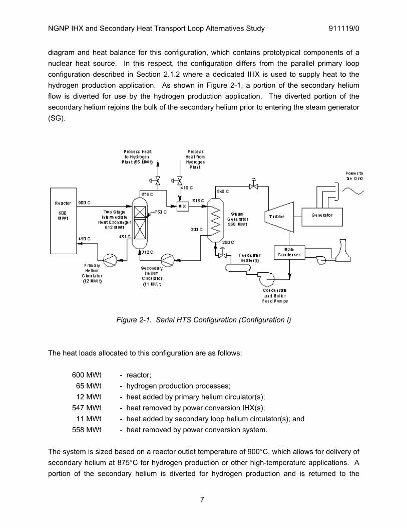
The serial HTS configuration uses a two-stage IHX to transfer heat from the primary coolant to a secondary loop that transports heat to the hydrogen production application or other high-temperature process heat application, and to the PCS. Figure 2-1 provides a schematic
NGNP IHX and Secondary Heat Transport Loop Alternatives Study 911119/0
7
diagram and heat balance for this configuration, which contains prototypical components of a nuclear heat source. In this respect, the configuration differs from the parallel primary loop configuration described in Section 2.1.2 where a dedicated IHX is used to supply heat to the hydrogen production application. As shown in Figure 2-1, a portion of the secondary helium flow is diverted for use by the hydrogen production application. The diverted portion of the secondary helium rejoins the bulk of the secondary helium prior to entering the steam generator (SG).
Figure 2-1. Serial HTS Configuration (Configuration I)
The heat loads allocated to this configuration are as follows:
600 MWt - reactor; 65 MWt - hydrogen production processes; 12 MWt - heat added by primary helium circulator(s); 547 MWt - heat removed by power conversion IHX(s); 11 MWt - heat added by secondary loop helium circulator(s); and 558 MWt - heat removed by power conversion system.
The system is sized based on a reactor outlet temperature of 900°C, which allows for delivery of secondary helium at 875°C for hydrogen production or other high-temperature applications. A portion of the secondary helium is diverted for hydrogen production and is returned to the
NGNP IHX and Secondary Heat Transport Loop Alternatives Study 911119/0
8
secondary loop at 410°C. The diverted secondary helium can supply a wide range of heat loads but is assumed to supply 65 MWt for hydrogen production. After mixing with the colder helium returning from the hydrogen production process, the secondary helium drops to about 815°C and continues to the SG of the PCS (or to some other more efficient PCS). If this HTS is operating with a reactor outlet helium temperature of 950°C, it can deliver secondary helium at 925°C for hydrogen production. After removing 65 MWt of heat for hydrogen production, the secondary helium continues on at 860°C to the SG. If only 5 MWt of heat at 925°C is removed for hydrogen production instead of 65 MWt, the secondary helium entering the SG would be 920°C, which would make SG design more difficult.
The two-stage IHX is designed to have a high-temperature stage and a low-temperature stage such that the low temperature stage can have an operating lifetime of 60 years. The 25°C temperature difference between the reactor outlet temperature and secondary helium exit temperature in the high-temperature IHX stage produces a relatively small LMTD and a large heat transfer surface area. The primary helium temperature exiting the high-temperature stage IHX could be either 800°C or 750°C, which would allow use of alloy 800H for the low-temperature stage. If the exit temperature of the high-temperature stage is 750°C, the LMTD for this stage is 46°C and the LMTD for the low-temperature stage is 117°C. The low LMTD and required heat duty of the high-temperature stage results in this IHX being larger than the low-temperature-stage IHX. If the exit temperature is raised to 800°C, the LMTD is 40°C for the high-temperature stage and 105°C for the low-temperature stage. The reduced heat duty for the high-temperature stage and increased heat duty for the low-temperature stage causes the high-temperature stage to be smaller in height and surface area compared to the low-temperature stage.
Both the compact PCHE and helical-coil (shell and tube) heat exchanger designs have been considered for the two-stage IHX as discussed in Section 4. The compact PCHE designs are much smaller than the shell and tube designs. As a result, pressure drops in the PCHE designs tend to be larger than in the shell and tube designs. The dominant factor in determining the number of primary loops and two-stage IHXs is the size of the IHXs. Pressure drop and circulator size are contributing factors in recommending two primary loops if a PCHE design is used for both IHX stages. The circulator size for a two-loop all-PCHE design is 5.5 MWe, which has predictable technical and schedule risk. Alternate two-stage IHX configurations in which either both stages are shell and tube designs, or only the low-temperature stage is a shell and tube design, will have lower pressure drops which require lower circulator power. As discussed in Section 4, the large size of the shell and tube designs would require a minimum of three primary loops.
NGNP IHX and Secondary Heat Transport Loop Alternatives Study 911119/0
9
In this HTS configuration, the helium inlet temperature to the PCS increases if the hydrogen production application heat load is reduced. If the hydrogen production application heat load is reduced to zero, the helium temperature into the PCS would be 875°C with the reactor outlet temperature at 900°C. (There would be no reason to operate the reactor with an outlet temperature of 950°C if no secondary helium is being diverted to hydrogen production.) With a helium inlet temperature of 875°C, the PCS could easily be a high efficiency gas turbine, gas turbine combined cycle, or sub-critical, super-critical or ultra-super-critical steam cycle. The SGs shown in Fig. 2-1 and sized to remove 558 MWt with an inlet temperature of 815°C are capable of removing 623 MWt with an inlet temperature of 875°C and a slight increase in feedwater temperature from 200°C to 204°C.
The inlet temperature to the SG could be as high as 920°C if only 5 MWt of heat at 925°C is being used for hydrogen production. One solution to reduce the technical challenges imposed by this temperature on SG design is to add a low-temperature bypass to reduce the inlet temperature to the SG. One or more bypass lines could be added to divert a portion of the low-temperature helium exiting the secondary helium circulator back into the high-temperature helium before it enters the SG. This diverted secondary helium flow would increase the mass flow rate through the PCS and the secondary helium circulator, which would increase the power requirement for the circulator.
2.1.2 Parallel Primary Loop Configuration
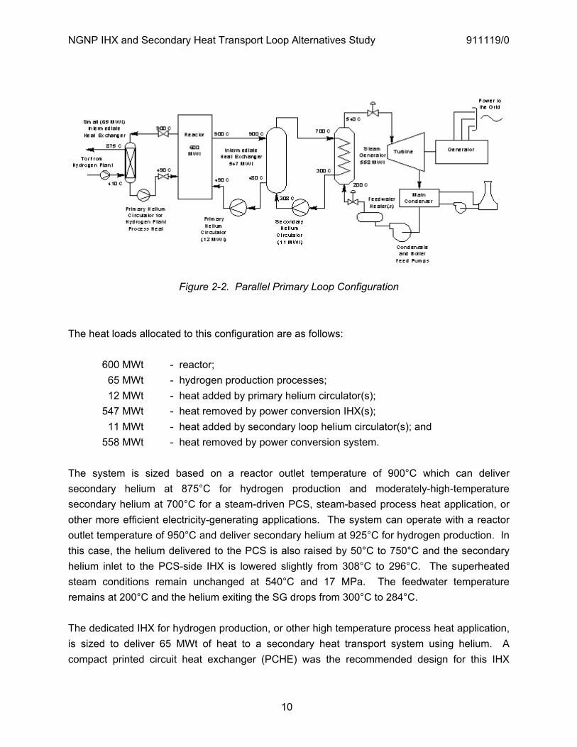
The parallel process heat and power conversion loop configuration separates the process heat function from the power conversion function by having a dedicated IHX to provide process heat to the hydrogen production application (H2-side IHX) or to other high-temperature process heat applications. In parallel, one or more power conversion loops provide high-temperature heat to the PCS via a PCS-side IHX. This configuration is shown in Figure 2-2.
NGNP IHX and Secondary Heat Transport Loop Alternatives Study 911119/0
10
Figure 2-2. Parallel Primary Loop Configuration
The heat loads allocated to this configuration are as follows:
600 MWt - reactor; 65 MWt - hydrogen production processes; 12 MWt - heat added by primary helium circulator(s); 547 MWt - heat removed by power conversion IHX(s); 11 MWt - heat added by secondary loop helium circulator(s); and 558 MWt - heat removed by power conversion system.
The system is sized based on a reactor outlet temperature of 900°C which can deliver secondary helium at 875°C for hydrogen production and moderately-high-temperature secondary helium at 700°C for a steam-driven PCS, steam-based process heat application, or other more efficient electricity-generating applications. The system can operate with a reactor outlet temperature of 950°C and deliver secondary helium at 925°C for hydrogen production. In this case, the helium delivered to the PCS is also raised by 50°C to 750°C and the secondary helium inlet to the PCS-side IHX is lowered slightly from 308°C to 296°C. The superheated steam conditions remain unchanged at 540°C and 17 MPa. The feedwater temperature remains at 200°C and the helium exiting the SG drops from 300°C to 284°C.
The dedicated IHX for hydrogen production, or other high temperature process heat application, is sized to deliver 65 MWt of heat to a secondary heat transport system using helium. A compact printed circuit heat exchanger (PCHE) was the recommended design for this IHX

NGNP IHX and Secondary Heat Transport Loop Alternatives Study 911119/0
11
during the pre-conceptual design (PCD) phase [PCDSR 2007] and remains the recommended design choice. In order to reduce the heat exchanger size, the log mean temperature difference (LMTD) of the H2-side IHX was increased from 25°C to 44°C. This increase in LMTD was achieved by increasing the temperature difference between the cold secondary and primary helium from 25°C to 70°C. The core inlet helium temperature was also reduced from 590°C to 490°C so that the secondary helium temperature entering the H2-side IHX is reduced from 565°C in the PCD design to 410°C.
The LMTD of the PCS-side IHX was selected to be as large as reasonable in order to minimize its size, thereby minimizing its cost. By lowering the IHX secondary helium exit temperature to 700°C and the IHX secondary helium inlet temperature to 308°C, the LMTD is about 186°C, which is over four times larger than the LMTD of the H2-side IHX. As a result of the large LMTD, the heat transfer surface area of the PCS-side IHX is only 20% larger than the surface area of the H2-side IHX assuming both of these IHXs are PCHEs. The large LMTD also reduces the temperature conditions imposed on the PCS-side IHX. The maximum mean metal temperature for the PCS-side IHX is 800°C when the reactor outlet temperature is 900°C. For the H2-side IHX, the maximum mean metal temperature is 888°C when the reactor outlet temperature is 900°C. Both maximum mean metal temperatures increase by 50°C when the reactor outlet temperature is raised to 950°C.
An alternate design choice for the PCS-side IHX discussed in Section 4 is the shell and tube design. The compact PCHE designs are much smaller than the shell and tube designs. As a result, pressure drops in the PCHE designs tend to be larger than the shell and tube designs. The dominant factor in determining the number of PCS loops depends on the PCS-side IHX design selection. For a shell and tube design, IHX size is the dominant factor and will likely result in a HTS configuration having two or three primary PCS loops. For a compact PCHE design, circulator power is the dominant factor. If technical and schedule risk are to be minimized, a PCHE-based HTS design having two PCS loops would limit the required helium circulator size to about 4.3 MWe, which would limit the technical risk associated with the circular. A PCHE-based HTS design with a single PCS loop would require a circulator twice as large (8.6 MWe).
In the operating mode when the H2-side IHX is not needed and has been isolated, it is highly desirable to generate as much power as possible with the PCS. In order for the SG to transfer 623 MWt of thermal energy to the PCS in the form of steam at 540°C and 17 MPa, the PCS-side IHX primary helium inlet temperature would have to be raised to 950°C, the secondary helium inlet temperature lowered to 286°C and the secondary helium outlet temperature raised to 725°C. With these temperature changes, the required steam conditions can be maintained if the SG feedwater temperature is lowered to 177°C. This lower feedwater temperature could be
NGNP IHX and Secondary Heat Transport Loop Alternatives Study 911119/0
12
factored into the design but would have a negative impact on thermal efficiency. The alternate operating mode when the H2-side IHX is isolated would be to reduce reactor power to 535 MWt and maintain the same PCS-side helium, steam, and feedwater conditions as when 65 MWt is being transferred to hydrogen production via the H2-side IHX. In this configuration, the SG would be sized for a heat transfer duty of 558 MWt.
An alternate approach is to size the PCS-side IHX and the SG to remove full reactor power when the reactor outlet temperature is 900°C. This approach results in a slightly larger IHX and SG. When 65 MWt of heat is being used for hydrogen production, the secondary helium exit temperature from the PCS-side IHX must be increased from 700°C to 731°C and the inlet temperature must be reduced from 308°C to 298°C to remove 547 MWt. The effect on the SG is that the feedwater temperature must be increased to 216°C. Superheat at the bimetallic weld decreases from 28°C to 23°C. If the reactor outlet temperature needs to be raised to 950°C, the secondary helium exit temperature from the PCS-side IHX must increase to 780°C and the secondary helium inlet temperature must be reduced to 288°C for the PCS-side IHX to transfer 547 MWt to the secondary loop. The effect on the SG is an increase in feedwater temperature to 217°C. However, under these conditions, superheat at the bimetallic weld is only 3.6°C, which is not sufficient to protect the bimetallic weld from frequent “wetting” events; consequently, this would not be a desirable mode of operation.
2.1.3 HTS Operation and Control
Conceptual descriptions of the reactor protection and control systems for the HTS configurations discussed in Sections 2.1.1 and 2.1.2 and for an additional HTS configuration in which the SG is located in the primary loop were developed as part of a companion NGNP conceptual design study of SG alternatives and are reported in [Labar 2008]. An overall conclusion of that work is that plant control and protection systems can be developed for each of the HTS configurations described in Sections 2.1.1 and 2.1.2 and that the design of these systems can be based on earlier MHR and HTGR control/protection concepts. The key concerns to be addressed are secondary loops incorporated in the reactor heat removal processes, development of dual-production control features, and selecting the most beneficial operational and safety features from the many possible options.
It was further concluded that at the current level of design detail, there is no clear preference for either one of these HTS configurations over the other based on a projection of the necessary control and protection design efforts. The design basis events for the reactor protection system (RPS) and the investment protection system are the same for the two configurations. Consequently, the “safety-related” logic for reactor trip and parallel “non-safety” actions for plant protection are also the same. However, one relatively minor difference is that the number of
NGNP IHX and Secondary Heat Transport Loop Alternatives Study 911119/0
13
potential secondary or process loop radiation pathway counts for the two configurations are different (i.e., four for the serial HTS configuration and six for the parallel primary loop configuration, assuming two PCS loops for both configurations).
2.1.4 Impact of HTS Configuration on Reactor Building Design Cost
2.1.4.1 Reactor Building Layout Options
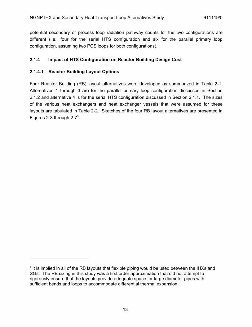
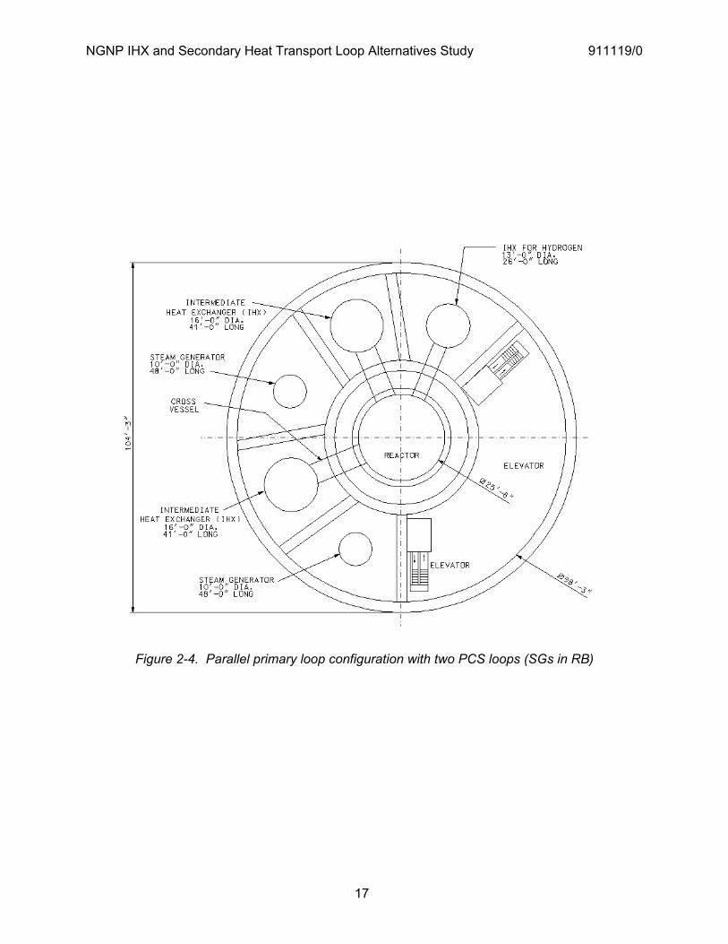
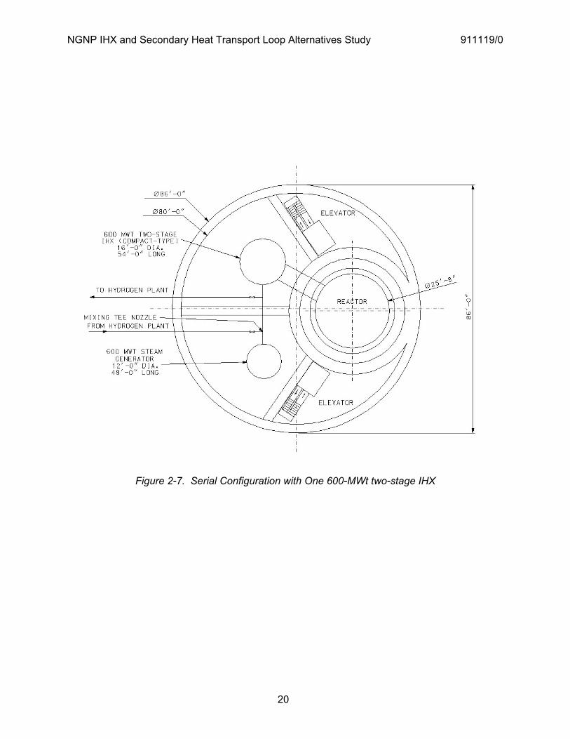
Four Reactor Building (RB) layout alternatives were developed as summarized in Table 2-1. Alternatives 1 through 3 are for the parallel primary loop configuration discussed in Section 2.1.2 and alternative 4 is for the serial HTS configuration discussed in Section 2.1.1. The sizes of the various heat exchangers and heat exchanger vessels that were assumed for these layouts are tabulated in Table 2-2. Sketches of the four RB layout alternatives are presented in Figures 2-3 through 2-73.
3 It is implied in all of the RB layouts that flexible piping would be used between the IHXs and SGs. The RB sizing in this study was a first order approximation that did not attempt to rigorously ensure that the layouts provide adequate space for large diameter pipes with sufficient bends and loops to accommodate differential thermal expansion.
NGNP IHX and Secondary Heat Transport Loop Alternatives Study 911119/0
14
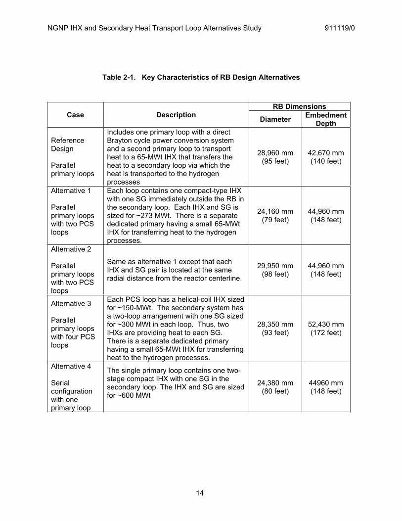
Table 2-1. Key Characteristics of RB Design Alternatives
RB Dimensions Case Description Diameter Embedment
Depth
ReferenceDesign
Parallelprimary loops
Includes one primary loop with a direct Brayton cycle power conversion system and a second primary loop to transport heat to a 65-MWt IHX that transfers the heat to a secondary loop via which the heat is transported to the hydrogen processes
28,960 mm (95 feet)
42,670 mm (140 feet)
Alternative 1
Parallelprimary loops with two PCS loops
Each loop contains one compact-type IHX with one SG immediately outside the RB in the secondary loop. Each IHX and SG is sized for ~273 MWt. There is a separate dedicated primary having a small 65-MWt IHX for transferring heat to the hydrogen processes.
24,160 mm (79 feet)
44,960 mm (148 feet)
Alternative 2
Parallelprimary loops with two PCS loops
Same as alternative 1 except that each IHX and SG pair is located at the same radial distance from the reactor centerline.
29,950 mm (98 feet)
44,960 mm (148 feet)
Alternative 3
Parallelprimary loops with four PCS loops
Each PCS loop has a helical-coil IHX sized for ~150-MWt. The secondary system has a two-loop arrangement with one SG sized for ~300 MWt in each loop. Thus, two IHXs are providing heat to each SG. There is a separate dedicated primary having a small 65-MWt IHX for transferring heat to the hydrogen processes.
28,350 mm (93 feet)
52,430 mm (172 feet)
Alternative 4
Serialconfiguration with one primary loop
The single primary loop contains one two-stage compact IHX with one SG in the secondary loop. The IHX and SG are sized for ~600 MWt
24,380 mm (80 feet)
44960 mm (148 feet)
NGNP IHX and Secondary Heat Transport Loop Alternatives Study 911119/0
15
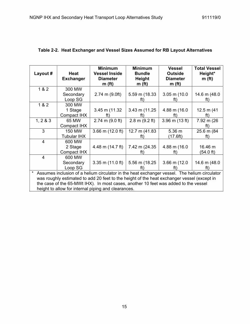
Table 2-2. Heat Exchanger and Vessel Sizes Assumed for RB Layout Alternatives
Layout # HeatExchanger
MinimumVessel Inside
Diameterm (ft)
MinimumBundleHeightm (ft)
VesselOutside
Diameterm (ft)
Total Vessel Height*m (ft)
1 & 2 300 MW SecondaryLoop SG
2.74 m (9.0ft) 5.59 m (18.33 ft)
3.05 m (10.0 ft)
14.6 m (48.0 ft)
1 & 2 300 MW 1 Stage
Compact IHX 3.45 m (11.32
ft)3.43 m (11.25
ft)4.88 m (16.0
ft)12.5 m (41
ft)1, 2 & 3 65 MW
Compact IHX 2.74 m (9.0 ft) 2.8 m (9.2 ft) 3.96 m (13 ft) 7.92 m (26
ft)3 150 MW
Tubular IHX 3.66 m (12.0 ft) 12.7 m (41.83
ft)5.36 m (17.6ft)
25.6 m (84 ft)
4 600 MW 2 Stage
Compact IHX 4.48 m (14.7 ft) 7.42 m (24.35
ft)4.88 m (16.0
ft)16.46 m (54.0 ft)
4 600 MW SecondaryLoop SG
3.35 m (11.0 ft) 5.56 m (18.25 ft)
3.66 m (12.0 ft)
14.6 m (48.0 ft)
* Assumes inclusion of a helium circulator in the heat exchanger vessel. The helium circulator was roughly estimated to add 20 feet to the height of the heat exchanger vessel (except in the case of the 65-MWt IHX). In most cases, another 10 feet was added to the vessel height to allow for internal piping and clearances.
NGNP IHX and Secondary Heat Transport Loop Alternatives Study 911119/0
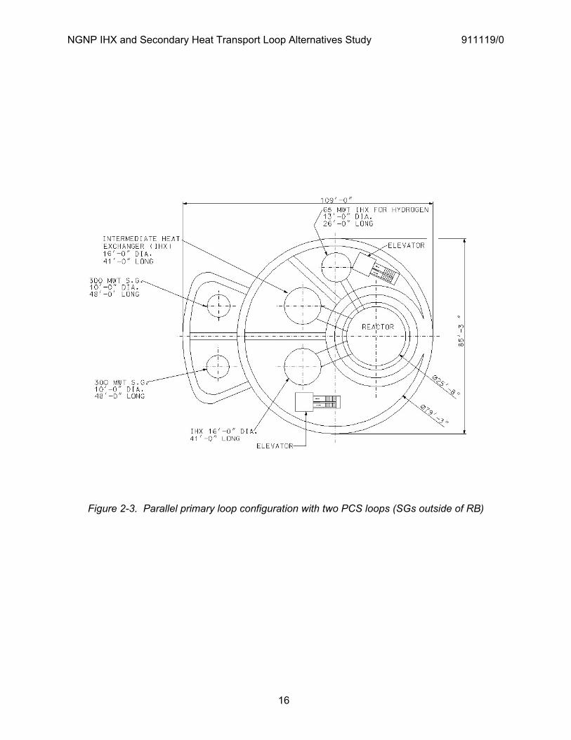
16
Figure 2-3. Parallel primary loop configuration with two PCS loops (SGs outside of RB)
NGNP IHX and Secondary Heat Transport Loop Alternatives Study 911119/0
17
Figure 2-4. Parallel primary loop configuration with two PCS loops (SGs in RB)

NGNP IHX and Secondary Heat Transport Loop Alternatives Study 911119/0
18
Figure 2-5. Parallel primary loop configuration with four PCS loops (SGs in RB)

NGNP IHX and Secondary Heat Transport Loop Alternatives Study 911119/0
19
Figure 2-6. Elevation View - Parallel primary loop configuration with four PCS loops
NGNP IHX and Secondary Heat Transport Loop Alternatives Study 911119/0
20
Figure 2-7. Serial Configuration with One 600-MWt two-stage IHX

NGNP IHX and Secondary Heat Transport Loop Alternatives Study 911119/0
21
2.1.4.2 Reactor Building Cost
The relative cost of each of the RB layouts shown in Figure 2-3 through 2-7 was evaluated with respect to the NGNP pre-conceptual RB design presented by the GA team in [PCDSR 2007]. The relative costs were estimated based on the following assumptions.
All constructions costs are 2007 dollars The “Greenfield” site is based in INL – Idaho The footprint for the NGNP Reactor Building prototype was used to scale capital costs for the alternative design building and concrete silo configurations All mechanical, architectural, electrical and steel liner costs are extrapolated costs based on the total volume of the below grade structure Capital costs reflect building costs only and exclude MHR plant equipment. Site-work includes lava rock excavation up to depths of 172’-00” Capital cost productivity for nuclear safety class 1 construction is reflected in all costs Limitations on ease of constructability of the concrete silos increases as the silo depth increases Physical constraints and increase costs are anticipated as the depth of the silo escalates Structural costs for the building decrease as the footprint of the above ground structure decreases due to reduction in the diameter of the concrete silo’s footprint The indirect costs account for construction services, home office engineering and services, field office engineering and services, owner’s cost Excludes initial core costs
Table 2-3 summarizes the relative capital costs of the different RB layout alternatives.
Table 2-3. Summary of Relative Capital Costs for RB Layout Alternatives
Scope of Work Prototype ($M)
Layout 1 Layout 2 Layout 3 Layout 4
Site-work 8.6 -11% 7% 13% -27% Concrete 38.9 -13% -2% -0.5% -19% Structural Steel 10.1 0% 0% 0% -27% Mechanical Systems 2.2 0% 0% 0% -27% Lighting 0.4 0.0% 0.0% 0.0% -26% Steel Liner 13.0 -8% 5% 9% -27% Total Direct Costs 73.2 -9% 0.6% 3% -23% Indirect Costs 181.2 -10% 1% -5% -28% Total 254.4 -10% 1% 3% -23%
NGNP IHX and Secondary Heat Transport Loop Alternatives Study 911119/0
22
In comparing the cost of the four layout alternatives that were considered, layout # 4 (serial HTS configuration with one primary loop) is the most economical, which is not surprising given that this layout benefits from having a single two-stage IHX.4 Consequently, this layout requires a smaller RB diameter, which results in less site work and less structural steel and concrete works. Layout #3 is the least economical with respect to RB capital cost. This layout also requires more site work than any of the other alternatives because of the deeper RB embedment depth required to accommodate the large helical-coil IHXs assumed for this alternative.
2.1.5 Comparison of HTS Configurations
There are advantages and disadvantages for both of the basic heat transport configurations described in Sections 2.1.1 and 2.1.2. The more important of these are as follows.
Serial HTS Configuration (Section 2.1.1) More flexible from the standpoint of being able to vary the respective loads for the hydrogen
plant (or other process heat application) and the PCS Better suited (than the parallel primary loop configuration) for inclusion or testing of a
prototypic gas turbine PCS in a secondary loop Less complicated and might entail lower capital costs Provides for a better demonstration of a full-size IHX such as would likely be used in a
commercial process heat generation plant Requires a larger IHX operating at higher temperatures than in the parallel primary loop
configuration; thus there is more risk associated with the IHX. (However, this risk can be mitigated somewhat with the two-stage IHX approach.)
More helium pumping power is needed – requires a larger helium circulator
Parallel Primary Loop Configuration (Section 2.1.2)
The steam generator does not need a high inlet helium temperature so the secondary loop hot-leg temperature can be set at 700°C to give a large IHX LMTD. The large LMTD
4 The compact IHX PCHE modules were sized using GA’s zigzag heat transfer correlation described in section 5.5.4. Further, the alternative assumed a two-stage IHX approach having high-temperature and low-temperature modules stacked together within one vessel, as opposed to the separate hot-stage and cold-stage IHX designs conceptualized by Toshiba and shown in Section 5.4.
NGNP IHX and Secondary Heat Transport Loop Alternatives Study 911119/0
23
sufficiently reduces the size of the IHX to make tube and shell heat exchangers feasible. The large LMTD reduces the size and cost of a compact-type heat exchanger and reduces mean IHX metal temperatures. However, the large LMTD will also increase thermal stresses, which could be a potential concern.
Allows demonstration of reactor operation with high helium outlet temperature without imposing overly severe demands on the IHX
Provides flexibility to test and demonstrate process heat technology and applications in the H2-side loop without impacting operation of the PCS
The secondary loop on the PCS side is prototypic of a commercial process steam/electricity cogeneration plant (same steam cycle as the 350-MWt SC-MHR)
Requires less helium pumping power, which reduces helium circulator cost and technology risk
2.2 Helium Circulator Technology Assessment
The IHX and HTS alternatives study included a sub-study performed by Rolls-Royce to assess the current state of helium circulator technology with respect to the anticipated circulator requirements for NGNP. This sub-study is of particular importance because the requirement that the NGNP utilize an indirect power conversion cycle potentially imposes stringent demands on helium circulator technology as well as on IHX technology. The availability of helium circulators that meet NGNP requirements could pose a risk to NGNP startup by 2018, so it is important for the NGNP Project to recognize and address any potential constraints associated with circulator technology at an early date. One possible impact on NGNP design imposed by helium circulator size limitations is with respect to the number of HTS loops that may be required. Key portions of the report prepared by Rolls-Royce [Rolls-Royce 2008] for the helium circulator technology assessment are summarized below.
Figure 2-8 shows a typical modern gas circulator design. All the rotating parts are submerged in the operating fluid. This means that there are no rotating gas seals, which would be potential gas leakage sites, would require cooling, might limit shaft speed, would need maintenance, and would be potential reliability concerns. The circulator is effectively separated into two zones. The impeller end is in the loop and is at the circulating working fluid temperature. Since this is too hot for standard electrical systems, the motor is in a separate cavity, which contains the working fluid at much lower temperature. The motor cavity requires cooling to remove the heat generated in normal operation and to remove any heat that is conducted from the primary circuit end of the machine. This heat is often removed using a water cooling loop. The motor itself is cooled by forced convection of the gas around the motor space and through a water heat exchanger. The motor cavity is separated from the impeller end by a non-contact seal to minimize gas mixing between the motor space and the operating end, and a thermal barrier.
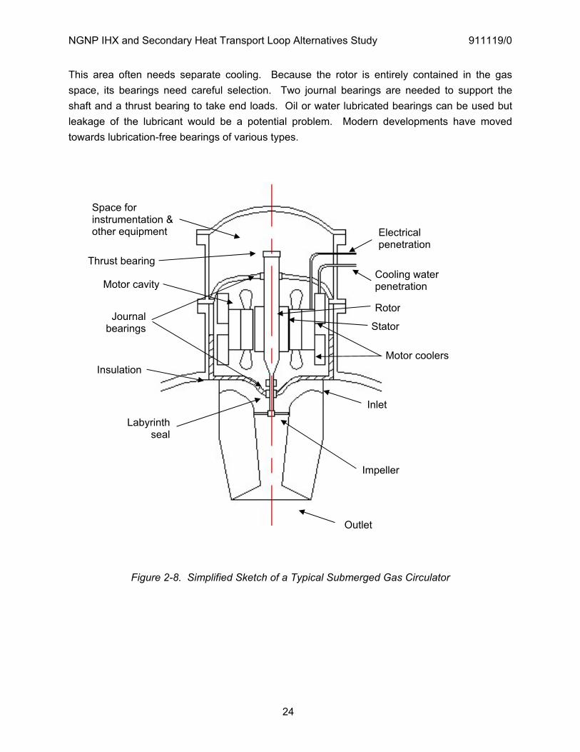
NGNP IHX and Secondary Heat Transport Loop Alternatives Study 911119/0
24
This area often needs separate cooling. Because the rotor is entirely contained in the gas space, its bearings need careful selection. Two journal bearings are needed to support the shaft and a thrust bearing to take end loads. Oil or water lubricated bearings can be used but leakage of the lubricant would be a potential problem. Modern developments have moved towards lubrication-free bearings of various types.
Figure 2-8. Simplified Sketch of a Typical Submerged Gas Circulator
Impeller
Outlet
Inlet
Labyrinthseal
Journalbearings
Thrust bearing
Electricalpenetration
Cooling waterpenetration
Stator
Motor coolers
Rotor
Space for instrumentation & other equipment
Motor cavity
Insulation
NGNP IHX and Secondary Heat Transport Loop Alternatives Study 911119/0
25
2.2.1 Circulator Requirements for NGNP
Table 2-4 summarizes helium circulator scoping parameters that GA defined for the purposes of the study. These parameters were used to produce a preliminary specification for discussion with potential helium circulator vendors. The possible loop options outlined in Table 2-4 are consistent with those defined in Sections 2.1.1 and 2.1.2, and in Section 3 of the companion SG alternatives study report [Labar 2008]. These configurations assume two power conversion loops, but the design chosen at a later stage of the project could feature one, two, or even three power conversion loops. Hence, the study focused on the issues associated with the higher-power, higher-flow-rate circulators that would be required for a plant design featuring one power conversion loop.
A required efficiency has not been defined for the helium circulators, however this is still an important factor, as helium circulator efficiency is likely to have an appreciable impact on overall plant efficiency. It will be important for the NGNP prototype to demonstrate efficient power production.
2.2.2 Helium Circulator Vendor Assessment
Six potential helium circulator vendors were contacted regarding their capability to design and produce high-temperature helium circulators. Sources used to identify potential vendors included internet searches, literature searches, expert recommendations, and the INL report “Conceptual Design for a High Temperature Gas Loop Test Facility” [INL 2006]. The vendors contacted were Howden (UK), Barber-Nichols, RIX Industries, Air Technologies, Shanghai Blower Works Co., and Sundyne Corporation. These vendors were asked initially whether they would be interested in discussion on providing high-temperature helium circulators for GA in support of NGNP. Four of these companies expressed an interest in further discussion and were sent basic details of the expected operating conditions and estimates of the range in mass flow rate and circulator power to be considered (up to 15 MWe).
From the responses received, Howden is considered to be the most credible vendor for design and production of helium circulators meeting the requirements of Table 2-4. Howden stated: “In summary we have the capability and expertise to design and supply a wide range of submerged gas circulators utilizing active magnetic bearings and fully submerged high speed electric drives, in combination with a range of aerodynamically efficient impellers and diffusers with high running and tip speeds suitable for helium coolant.” Howden’s full response to the preliminary specification provided by Rolls-Royce is included in [Rolls-Royce 2008].
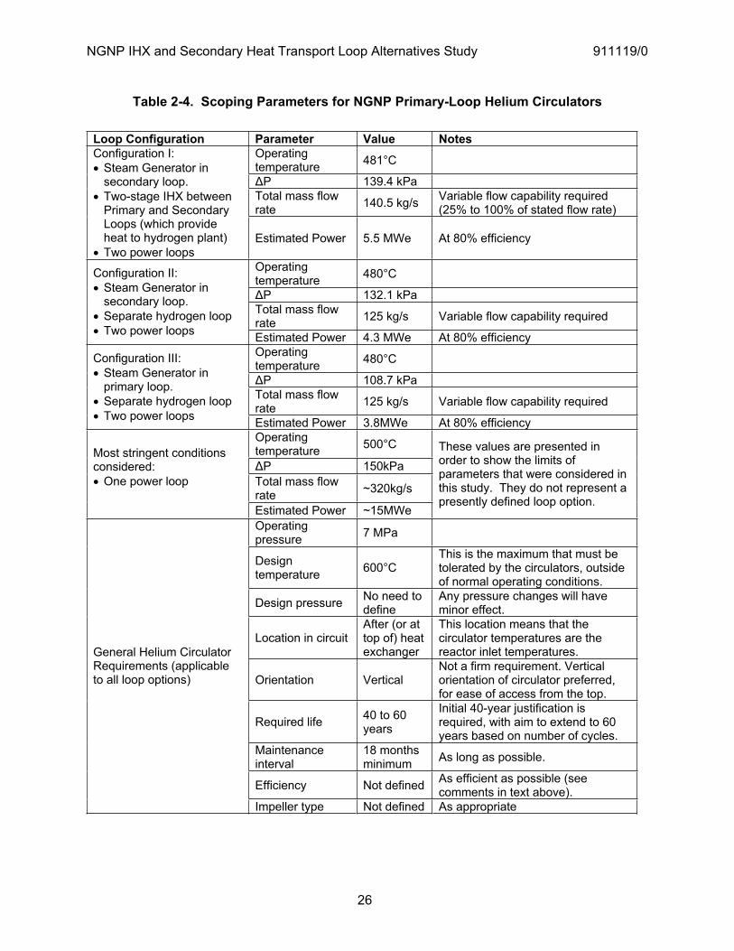
NGNP IHX and Secondary Heat Transport Loop Alternatives Study 911119/0
26
Table 2-4. Scoping Parameters for NGNP Primary-Loop Helium Circulators
Loop Configuration Parameter Value Notes Operating temperature 481°C
P 139.4 kPa Total mass flow rate 140.5 kg/s Variable flow capability required
(25% to 100% of stated flow rate)
Configuration I: Steam Generator in secondary loop.
Two-stage IHX between Primary and Secondary Loops (which provide heat to hydrogen plant)
Two power loops Estimated Power 5.5 MWe At 80% efficiency
Operating temperature 480°C
P 132.1 kPa Total mass flow rate 125 kg/s Variable flow capability required
Configuration II: Steam Generator in secondary loop.
Separate hydrogen loop Two power loops Estimated Power 4.3 MWe At 80% efficiency
Operating temperature 480°C
P 108.7 kPa Total mass flow rate 125 kg/s Variable flow capability required
Configuration III: Steam Generator in primary loop.
Separate hydrogen loop Two power loops Estimated Power 3.8MWe At 80% efficiency
Operating temperature 500°C
P 150kPa Total mass flow rate ~320kg/s
Most stringent conditions considered: One power loop
Estimated Power ~15MWe
These values are presented in order to show the limits of parameters that were considered in this study. They do not represent a presently defined loop option.
Operating pressure 7 MPa
Design temperature 600°C
This is the maximum that must be tolerated by the circulators, outside of normal operating conditions.
Design pressure No need to define
Any pressure changes will have minor effect.
Location in circuit After (or at top of) heat exchanger
This location means that the circulator temperatures are the reactor inlet temperatures.
Orientation Vertical Not a firm requirement. Vertical orientation of circulator preferred, for ease of access from the top.
Required life 40 to 60 years
Initial 40-year justification is required, with aim to extend to 60 years based on number of cycles.
Maintenance interval
18 months minimum As long as possible.
Efficiency Not defined As efficient as possible (see comments in text above).
General Helium Circulator Requirements (applicable to all loop options)
Impeller type Not defined As appropriate
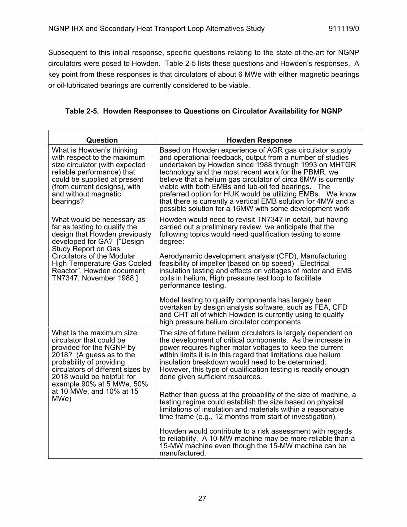
NGNP IHX and Secondary Heat Transport Loop Alternatives Study 911119/0
27
Subsequent to this initial response, specific questions relating to the state-of-the-art for NGNP circulators were posed to Howden. Table 2-5 lists these questions and Howden’s responses. A key point from these responses is that circulators of about 6 MWe with either magnetic bearings or oil-lubricated bearings are currently considered to be viable.
Table 2-5. Howden Responses to Questions on Circulator Availability for NGNP
Question Howden Response What is Howden’s thinking with respect to the maximum size circulator (with expected reliable performance) that could be supplied at present (from current designs), with and without magnetic bearings?
Based on Howden experience of AGR gas circulator supply and operational feedback, output from a number of studies undertaken by Howden since 1988 through 1993 on MHTGR technology and the most recent work for the PBMR, we believe that a helium gas circulator of circa 6MW is currently viable with both EMBs and lub-oil fed bearings. The preferred option for HUK would be utilizing EMBs. We know that there is currently a vertical EMB solution for 4MW and a possible solution for a 16MW with some development work
What would be necessary as far as testing to qualify the design that Howden previously developed for GA? [“Design Study Report on Gas Circulators of the Modular High Temperature Gas Cooled Reactor”, Howden document TN7347, November 1988.]
Howden would need to revisit TN7347 in detail, but having carried out a preliminary review, we anticipate that the following topics would need qualification testing to some degree:
Aerodynamic development analysis (CFD), Manufacturing feasibility of impeller (based on tip speed) Electrical insulation testing and effects on voltages of motor and EMB coils in helium, High pressure test loop to facilitate performance testing.
Model testing to qualify components has largely been overtaken by design analysis software, such as FEA, CFD and CHT all of which Howden is currently using to qualify high pressure helium circulator components
What is the maximum size circulator that could be provided for the NGNP by 2018? (A guess as to the probability of providing circulators of different sizes by 2018 would be helpful; for example 90% at 5 MWe, 50% at 10 MWe, and 10% at 15 MWe)
The size of future helium circulators is largely dependent on the development of critical components. As the increase in power requires higher motor voltages to keep the current within limits it is in this regard that limitations due helium insulation breakdown would need to be determined. However, this type of qualification testing is readily enough done given sufficient resources.
Rather than guess at the probability of the size of machine, a testing regime could establish the size based on physical limitations of insulation and materials within a reasonable time frame (e.g., 12 months from start of investigation).
Howden would contribute to a risk assessment with regards to reliability. A 10-MW machine may be more reliable than a 15-MW machine even though the 15-MW machine can be manufactured.

NGNP IHX and Secondary Heat Transport Loop Alternatives Study 911119/0
28
2.2.3 Evaluation of Helium Circulator Technology
2.2.3.1 Technology Development Needs
This section summarizes the key circulator technology development areas required for NGNP start-up by 2018. It excludes the general design development work that will be required, which is discussed in detail for the key components in [Rolls-Royce 2008].
Circulator size is the variable that is likely to have the biggest impact on the amount of technology development required. The largest circulator size that should be considered for NGNP is about 15 MWe. This view is backed by the input from Howden included in Table 2-5.
For a circulator of about 5 MWe, the key technology development areas are:
Performance testing of developed journal and thrust active magnetic bearing (AMB) systems against project requirements (essential). This would include consideration of weight support, control and speed capability, redundancy and fault conditions, and would interface with balance requirements.
Sub-scale testing of catcher bearings under representative conditions, considering the specified life requirement of 20 operations (essential). To advance the state-of-the-art, research and development into improved catcher bearing materials is also needed.
Testing of electrical insulation (for both motors and AMBs), in a representative helium environment, given the required voltages.
Development of gas bearings (optional, and less likely to be taken forward than AMBs) - Component testing for weight-bearing capability - Component testing for stiffness suitability, especially with regard to maintaining tip
clearances - Component testing for start-up and low speed requirements - Component testing for unbalance load capability - Research and testing of coatings against life requirements.
Prototype demonstration in an operational environment (essential).
For a circulator of about 10 MWe or greater power, an additional technology development area is testing of the physical limitations of the power supply insulation with regard to preventing significant dielectric losses (essential).
The development areas listed for circulators of about 5 MWe will require more extensive development and testing as circulator size increases because the weight, control, and imbalance loads become more significant; the AMB windings will require higher supply voltages,
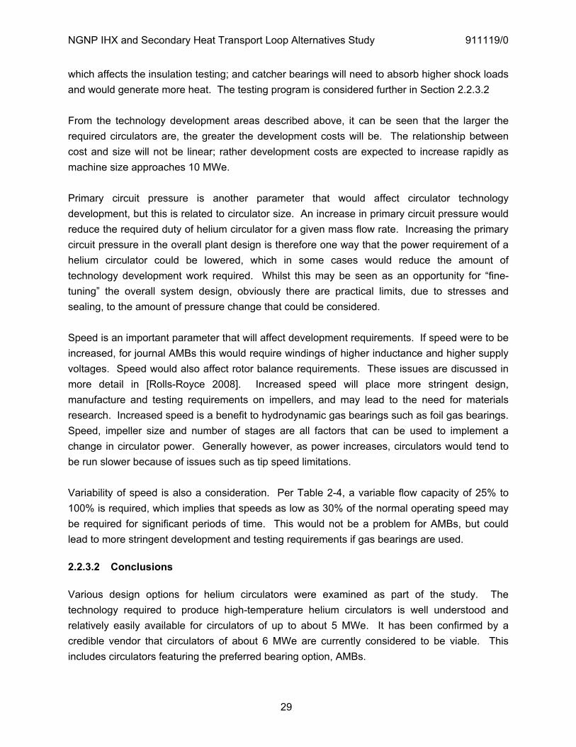
NGNP IHX and Secondary Heat Transport Loop Alternatives Study 911119/0
29
which affects the insulation testing; and catcher bearings will need to absorb higher shock loads and would generate more heat. The testing program is considered further in Section 2.2.3.2
From the technology development areas described above, it can be seen that the larger the required circulators are, the greater the development costs will be. The relationship between cost and size will not be linear; rather development costs are expected to increase rapidly as machine size approaches 10 MWe.
Primary circuit pressure is another parameter that would affect circulator technology development, but this is related to circulator size. An increase in primary circuit pressure would reduce the required duty of helium circulator for a given mass flow rate. Increasing the primary circuit pressure in the overall plant design is therefore one way that the power requirement of a helium circulator could be lowered, which in some cases would reduce the amount of technology development work required. Whilst this may be seen as an opportunity for “fine-tuning” the overall system design, obviously there are practical limits, due to stresses and sealing, to the amount of pressure change that could be considered.
Speed is an important parameter that will affect development requirements. If speed were to be increased, for journal AMBs this would require windings of higher inductance and higher supply voltages. Speed would also affect rotor balance requirements. These issues are discussed in more detail in [Rolls-Royce 2008]. Increased speed will place more stringent design, manufacture and testing requirements on impellers, and may lead to the need for materials research. Increased speed is a benefit to hydrodynamic gas bearings such as foil gas bearings. Speed, impeller size and number of stages are all factors that can be used to implement a change in circulator power. Generally however, as power increases, circulators would tend to be run slower because of issues such as tip speed limitations.
Variability of speed is also a consideration. Per Table 2-4, a variable flow capacity of 25% to 100% is required, which implies that speeds as low as 30% of the normal operating speed may be required for significant periods of time. This would not be a problem for AMBs, but could lead to more stringent development and testing requirements if gas bearings are used.
2.2.3.2 Conclusions
Various design options for helium circulators were examined as part of the study. The technology required to produce high-temperature helium circulators is well understood and relatively easily available for circulators of up to about 5 MWe. It has been confirmed by a credible vendor that circulators of about 6 MWe are currently considered to be viable. This includes circulators featuring the preferred bearing option, AMBs.

NGNP IHX and Secondary Heat Transport Loop Alternatives Study 911119/0
30
As circulator power is increased, the development funding required, the testing requirements, and the manufacturing expenses of the circulator also increase. The relationship between cost and size will not be linear; rather development costs are expected to increase rapidly as machine size approaches 10 MWe. Considering the start-up date of 2018 and the need to achieve a technology readiness level (TRL) of at least 8 by this date, the largest circulator power that should be considered for NGNP is about 15 MWe. Circulator development risks should be mitigated by implementation of an early test program designed to check feasible limits of circulator operation. Further, optimization of the circulator design as a whole should be the subject of a more detailed design study. An expert organization, such as a circulator vendor, should be engaged by the NGNP Project at an early date to develop a circulator design and a demonstration/qualification program for the design.
Bearings are the main area identified for technology development in support of NGNP. AMBs are the lubrication-free, low-maintenance bearing option that is most likely to be taken forward for NGNP. The operating speeds and loads required for the AMB system will determine the level of development and testing work required. Performance testing of developed journal and thrust AMB systems against project requirements is essential. This would include consideration of weight support, control and speed capability, redundancy and fault conditions, and would interface with balance requirements. Sub-scale testing of catcher bearings under representative conditions, considering the specified life requirement of 20 operations, is required. In order to advance the state-of-the-art, research and development into improved catcher bearing materials is also needed.
Gas bearings are an alternative lubrication-free, low-maintenance option, which appear to be feasible, for both journal and thrust applications. These have the benefit of passive operation, (unlike AMBS). There is extensive positive previous experience of gas bearings for small machines running in both air and helium, typically for machines of around 100 kW. There is little experience at the required scale. However, scoping calculations indicate that the load-bearing capability of gas bearings significantly exceeds the loads supported in typical current applications. Low speed operation would require further investigation for gas bearings, since these become less effective as speed decreases.
Traditional bearing types, lubricated by oil or water, are the most mature technology, but they are not recommended for further development in support of NGNP. This is due to past leakage problems. Although such problems may be overcome by development of sealing technology, there would still be difficulty in justifying such designs from a safety perspective, when lubricant-free designs are available.

NGNP IHX and Secondary Heat Transport Loop Alternatives Study 911119/0
31
There are many factors that affect the selection of impeller type. In general, radial or mixed flow impellers are cheaper and more robust. However, a greater efficiency is achievable with axial impellers, which also have other advantages. If axial impellers are selected, potential areas for further development are suitable creep-resistant materials for the specific application and tip sealing development.
On balance, an induction motor is likely to be preferable to a permanent magnet motor for this application. Both motor-types are mature technologies, but various development areas have been identified that relate to the design for the specific application required. The design of the interface between the motor cavity and the primary circuit is an important area for consideration. It is suggested that a pressurized, cooled labyrinth seal is used at this interface. Pressurization of the labyrinth seal would prevent primary helium contamination of the motor cavity, as well as ingress of any motor cavity contaminants into the primary circuit. A high-level design concept is provided in [Rolls-Royce 2008] for a pressurized and cooled labyrinth seal.
The potential development areas mentioned above for axial impellers, motors and the motor cavity are all desirable, but generally do not pose a threat to the 2018 start-up date. In order to achieve a TRL of at least 8 by 2018, the essential technology development areas for an AMB-based circulator are:
Performance testing of developed journal and thrust AMB systems against project requirements. This would include consideration of weight support, control and speed capability, redundancy and fault conditions, and would interface with balance requirements.
Sub-scale testing of catcher bearings under representative conditions, considering the specified life requirement of 20 operations (to advance the state-of-the-art, research and development into improved catcher bearing materials is also needed).
Testing of electrical insulation (for both motors and AMBs), in a representative helium environment, given the required voltages.
Prototype demonstration in an operational environment (essential).
Additionally, testing of the physical limitations of the power supply insulation, with regard to preventing significant dielectric issues, would be required for a circulator of about 10 MWe or greater power.
The most credible vendor that can currently be identified for production of high-temperature helium circulators is Howden (UK). Howden is a well-established company with a history of design and supply of gas circulators to several types of gas-cooled reactor, including helium-cooled reactors. Howden can design and supply circulators with AMBs.

NGNP IHX and Secondary Heat Transport Loop Alternatives Study 911119/0
32
2.3 Isolation Valves
2.3.1 Requirements for NGNP
Parallel hot leg and cold leg piping is used to transfer secondary helium from the IHX to the hydrogen production plants and to the PCS. The piping between the IHX and process heat exchangers of either the SI-based or HTE-based hydrogen production demonstration plants is assumed to run 90-m in length. The parallel pipe configuration is a simpler design compared to a concentric pipe configuration and can more easily accommodate the design features necessary to address thermal expansion.
The secondary heat transport loop between the IHX and hydrogen production plants will likely have three isolation valves on each hot and cold leg. Two of the valves would be located near the IHX and one or more valves would be located hear the process heat exchangers. Isolation valves are useful in preventing the propagation of events in either the NGNP reactor or hydrogen production plant from affecting the other. Isolation valves are also necessary to allow maintenance to be performed on the secondary heat transport loop. Double isolation valves on the hot leg and cold leg sides of the IHX allow these isolation valves to be part of the primary coolant pressure boundary and part of the containment building boundary.
2.3.2 Evaluation of Technology Readiness
As part of JAEA’s plan to demonstrate hydrogen production with the High Temperature Engineering Test Reactor (HTTR), a high-temperature isolation valve (HTIV) must be installed in the secondary helium hot gas duct, which penetrates the reactor containment vessel. Development of the HTIV is underway. The technical issues are as follows: (1) prevention of the valve seating from thermal deformation, (2) development of a new material for the valve seat surface, and (3) selection of a valve seat structure having a high sealing performance. An angle valve with an inner thermal insulator was selected as shown in Figure 2-9. A new valve seat material, with sufficient hardness and wear resistance over 900°C, was developed on the Stellite alloy that is used for valves at around 500°C. The rod body and seat were made of Hastelloy X and the seat had a coating metal of Stellite No. 6 and 30 wt% Cr3C2. The casing of the valve was made of carbon steel with internal glass wool insulation which limited the temperature to 350°C. A component test of the valve seat indicates that a flat type valve seat can maintain the face roughness of the valve seat within allowable limits during operation. A ½ scale model of the HTIV was fabricated to confirm seal performance and structural integrity. The helium leak rate was confirmed to be less than the target value [Nishihara 2004].
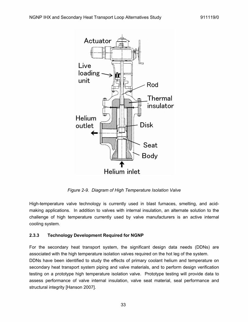
NGNP IHX and Secondary Heat Transport Loop Alternatives Study 911119/0
33
Figure 2-9. Diagram of High Temperature Isolation Valve
High-temperature valve technology is currently used in blast furnaces, smelting, and acid-making applications. In addition to valves with internal insulation, an alternate solution to the challenge of high temperature currently used by valve manufacturers is an active internal cooling system.
2.3.3 Technology Development Required for NGNP
For the secondary heat transport system, the significant design data needs (DDNs) are associated with the high temperature isolation valves required on the hot leg of the system. DDNs have been identified to study the effects of primary coolant helium and temperature on secondary heat transport system piping and valve materials, and to perform design verification testing on a prototype high temperature isolation valve. Prototype testing will provide data to assess performance of valve internal insulation, valve seat material, seal performance and structural integrity [Hanson 2007].

NGNP IHX and Secondary Heat Transport Loop Alternatives Study 911119/0
34
3. IHX MATERIAL ALTERNATIVES
3.1 Material Options
For the IHX to function at elevated temperatures in a VHTR, the pressure in the primary and secondary coolant loops are essentially balanced so that the pressure difference across the heat transfer tubing (or plates) in the IHX is essentially zero during normal operation. This allows relatively thin-walled tubing to be used and the wall thickness of the tubing is sized to give the IHX the ability to withstand the short-term loads due to the pressure differential resulting from the accidental depressurization of one loop. The use of thin-walled tubing (or plates) allows temperature differentials across tube walls to be minimized, thus minimizing creep-fatigue effects due to the temperature differentials. Despite these design features, the design of an IHX for operation at temperatures up to 950°C is very challenging, particularly with respect to materials selection. The material considerations that are important to the IHX are essentially the same as those that are pertinent to steam generators (e.g., tensile, creep-rupture, and creep-fatigue properties; long-term effects of interaction with impurities in the helium; and thermal aging and embrittlement), but many of the property changes and environmental effects are accelerated because of the much higher operating temperatures. Additionally, the candidate materials will need to be readily available in the product forms most compatible with manufacture of heat exchangers (e.g., plate, sheet, and tubing).
Table 6 of the NGNP Materials R&D Program Plan [MRDPP 2005] provides a list of potential candidate materials for the IHX and other NGNP high-temperature components; however, only a few of these are actually considered to be viable due a lack of materials property data or ASME code acceptance. Based on creep resistance above 850°C, the leading candidate alloys for the NGNP IHX are alloy 617 and Haynes 230. However, Hastelloy XR, which was developed by the Japanese for use in the HTTR IHX, is another possibility. During the Generation IV Nuclear Energy Systems Program, alloy 800H was also evaluated as a potential material for the NGNP IHX and a significant amount of data up to 1000°C was collected. The data showed that there was some creep strength at these high temperatures, but the slope of the curve in this higher temperature regime is very steep and not very predictable. The overall conclusion of this evaluation was that alloy 800H is not a viable candidate material for the NGNP IHX and only two materials should be considered - alloy 617 and Haynes 230. The properties of both are similar. At the lower temperatures, Haynes 230 has an edge, but at the higher temperatures alloy 617 is a slightly better material. In addition, alloy 617 has been used in a wider of range of section thicknesses than Haynes 230. In the past, there were a number of problems resulting from the welding of alloy 617, including stress induced cracking in the weld heat affected zone and in cold worked areas; however, these problems were resolved by using a post-weld heat treatment.

NGNP IHX and Secondary Heat Transport Loop Alternatives Study 911119/0
35
Currently, neither alloy 617 nor Haynes 230 is approved for use in Section III Class 1, 2 and 3 or in the high temperature NH section of the ASME Code. They are both approved up to 982°C in Section VIII Div 1. Table 3-1 provides the maximum allowable stresses from ASME Section II Part D Table 1 for alloy 617, Haynes 230, and alloy 800H at the design temperatures of 900°C and 950°C. Even for alloy 617 and Haynes 230, the allowable stress levels for Section VIII Div 1 are quite low at 900°C and 950°C.
Table 3-1. ASME Section VIII Div 1 - Allowable Stresses
ASME Product Specs Allowable Stress 900°C
Allowable Stress 950°C
SB 168 Plate Alloy 617 1.8 ksi 1.1 ksi
SB 564 Forging Alloy 617 1.8 ksi 1.1 ksi
SB 435 Plate Alloy 230 1.5 ksi 0.7 ksi
SB 564 Forging Alloy 230 1.5 ksi 0.7 ksi
SB 409 Plate Alloy 800H* 0.86 ksi Not permitted
SB 564 Forging Alloy 800H* 0.86 ksi Not permitted *All product forms have a 2.6 ksi maximum allowable stress at 760°C in ASME Section III Part NH
.
Another important consideration in selecting a material for a VHTR IHX is that one aspect of materials behavior over which temperature has a strong influence is the interaction of the material with impurities in the helium. At 950°C, the combination of impurities present in the primary helium coolant will tend to be more reducing and carburizing than at lower temperatures. As reported in [Johnson 1983], experimental evaluations of materials behavior in VHTR-type environments performed in the 1970’s and early 1980’s indicated that carburization rates become very high for commercially available wrought alloys such as alloy 800H, alloy 617, and Hastelloy X at temperatures above about 700°C. This is undesirable because carburization causes embrittlement of many wrought alloys, including alloy 800H and alloy 617. Carburization also has the potential to affect other key properties such as creep, rupture, fatigue, and creep-fatigue.

NGNP IHX and Secondary Heat Transport Loop Alternatives Study 911119/0
36
Since its inception, the NGNP R&D Program has concentrated on alloy 617 because it is the most mature with respect to data availability, has superior creep resistance at the high end of the anticipated NGNP temperature range (950°C), and is considered to be the closest to gaining ASME code approval in Section III. In particular, much work on alloy 617 was performed in Germany following termination of US interest in nuclear applications of this alloy in the late 1980’s. As part of the Gen IV Program, there has been an effort at ORNL to compile the available international data on alloy 617 for the Gen IV material handbook [Ren, 2005]. A second effort with respect to alloy 617 at ORNL has been to refine the standard specification for alloy 617 to obtain a more uniform product for use in VHTRs. This effort resulted in a recommended refined chemical composition specification for alloy 617 for VHTR materials testing. According to [MRDPP 2005], the NGNP R&D Program also plans to include testing of Haynes 230 and Hastelloy XR, but acknowledges that given the multiplicity of alloys, joining conditions, and creep-fatigue test conditions, it will be necessary to eventually make a down selection to limit the testing to a reasonably manageable effort. [Wright 2006b] discusses the results from a program to study the microstructure and mechanical properties of alloy 617 and Haynes 230 aged in air at temperatures up to 1000°C. These aging effects tests were carried out on two commercial heats of alloy 617 and one heat of Haynes 230.
There are, however, two potential concerns with respect to the use of alloy 617 in VHTR heat exchangers. The first, as noted above, is that alloy 617, as well as most other commercially available wrought alloys, have been found in extensive testing performed in the 1970’s and 1980’s to have poor resistance to corrosion in impure helium at VHTR temperatures [Johnson 1983]. Specifically, the Cr-rich surface scale that forms on alloy 617 after exposure at 800°C to 900°C in an impure helium environment was found to provide little or no protection against carbon ingress in tests performed in simulated reactor helium; consequently, the alloy experienced significant carburization in these tests.
The second concern is that alloy 617 contains about 12.5% cobalt and that potential spallation of cobalt that becomes trapped in the surface scale that forms during high-temperature exposure to impure helium could result in cobalt particulates being entrained in the primary coolant. Activation of such particulates in the reactor core could result in very high radiation levels in the primary circuit. These two concerns prompted GA to conduct a high-temperature materials development program in the late 1970’s and early 1980’s to develop a low-cobalt alloy having improved corrosion resistance relative to alloy 617 and other commercially available wrought alloys [Johnson 1982]. Ten cobalt-free experimental alloys were developed, and all of them were determined to be more carburization resistant than alloy 617. Three of these alloys also had higher tensile properties at 900°C than alloy 617. This development program was terminated soon after these results were reported and apparently none of these alloys were further developed for commercial use.
NGNP IHX and Secondary Heat Transport Loop Alternatives Study 911119/0
37
Given the improvements in alloy 617 manufacturing since the 1970’s and the likelihood that the coolant chemistry will be different in NGNP than in early HTGRs, it is difficult to assess the extent to which carburization of alloy 617 or other candidate IHX materials may represent a potential problem for the NGNP. However, it is clear that it is essential that the environmental effects testing planned in the NGNP materials R&D program be conducted to resolve this potential concern.
3.2 ASME Code Issues
In the NGNP IHX designs, the IHX vessel is the primary pressure retaining member and is maintained at temperature cool enough to minimize creep effects. The internal heat transfer portion of the IHX, which is exposed to the full reactor outlet temperature, is the boundary between the primary and secondary loops and therefore has a pressure boundary function even though it is not exposed to the difference between the system operating pressure and atmospheric pressure except during a potential primary or secondary loop depressurization event. Since the heat transfer portion of the IHX is not part of the external pressure boundary and because secondary loop designs will likely include an isolation valve to isolate the secondary loop from the primary loop in the event of a failure of the IHX, one could question the need for ASME Section III code rules to cover the IHX. However, there is little question that codification in ASME Section VIII will, as a minimum, be necessary. This is desirable for achieving a reliable design that protects the reactor from possible ingress of water or chemicals from the secondary circuit and protects the secondary loop from radionuclide contamination from the primary circuit, and it will likely be essential to obtain NRC approval. There is also a precedent in that the tubes of tube and shell heat exchangers are designed as a pressure boundary in accordance with Section VIII of the ASME code.
Accordingly, a task was planned within the NGNP Materials R&D Program to determine how and where within the ASME codes and standards the IHX and isolation valves should be addressed. In order to answer this question, there are many questions that need to be addressed to determine how the function of these components within a particular plant design affects plant operation, safety, and economic risk. Clearly, a substantial amount of data will have to be developed in order to develop a nuclear code case. As noted above, one of the primary reasons for selection of alloy 617 as the leading material candidate for the NGNP IHX is that it is the material considered to be the closest to gaining ASME code approval in Section III.
3.3 Conclusions and Recommendations
For the same reasons that the NGNP Project has adopted alloy 617 as the leading candidate for the NGNP IHX, GA selected this material as its choice for the IHX in [PCDSR 2007]. This

NGNP IHX and Secondary Heat Transport Loop Alternatives Study 911119/0
38
material appears to be a better choice than the other leading candidate, Haynes 230, because of its greater high temperature creep resistance and greater stress allowables above 850°C. However, GA recommended in both [PCDSR 2007] and herein that the reactor outlet temperature be limited to a temperature less than 950°C (i.e., 850°C – 900°C) because 950°C is at the fringe of the useful range of the viable metal material options. Consequently, the risk associated with the performance and operational lifetime of the IHX at 950°C would be very high. With the two-stage IHX concept, the larger second stage, which would operate at a lower temperature, might be made of Haynes 230. Alloy 800H might also be a candidate for the second stage IHX. Indeed, GA specified the inlet temperature of the second-stage IHX to be 750°C in the parallel primary loop configuration described in Section 2.1.2 to keep the temperature within the temperature limit for which alloy 800H is approved for use in Section III of the ASME code. However, this temperature constraint on the low-temperature IHX is not practical because it is not consistent with the concept that the high-temperature IHX should be a smaller IHX that would be periodically replaced while the low-temperature IHX should be a larger IHX capable of operating for the lifetime of the plant (assumed to be 60 years).
Operating the NGNP at a moderately lower reactor outlet temperature, as proposed herein would increase the relative attractiveness of Haynes 230 vs. alloy 617. A further consideration that enhances the attractiveness of Haynes 230 relative to alloy 617 is its much lower cobalt content (about 5% vs. 12.5% for alloy 617). A primary principle of reactor design has been to avoid inclusion of high cobalt materials in the primary circuit given the potential for cobalt activation, which would lead to higher radiation levels in the primary coolant with the attendant potential for higher worker doses. While it is by no means clear that there is a significant potential for cobalt to be eroded from the IHX and entrained in the primary coolant, this is not certain.
With respect to cobalt content, Hastelloy XR with essentially no cobalt would be an even better choice, and this was in fact a primary reason for selection of the material as the material of construction for the HTTR IHX. It is particularly interesting to note that the Japanese evaluated other alloys, including Alloy 617 prior to the development of Hastelloy XR. Given that the HTTR represents the most recent actual application of resources for the design, materials, and fabrication of an IHX for the VHTR, the material selected for the HTTR IHX should be given serious consideration in the event that the Japanese data base for this material were to be made available to the NGNP Project or to the ASME.
3.4 Ion Beam Coating/Mixing Process
KAERI has developed a metallic surface modification process that has potential applications in the NGNP. In the process developed at KAERI, a SiC film is deposited on the surface of
NGNP IHX and Secondary Heat Transport Loop Alternatives Study 911119/0
39
Hastelloy X and is fastened to the metal substrate by ion beam bombardment. The mixing of the SiC film and substrate metal that results from the ion beam bombardment (I.e., “ion beam mixing”) keeps the SiC film from peeling off the substrate metal before the interfacial reaction that bonds the SiC coating to the Hastelloy X is completed during heat treatment of the SiC coated substrate. Once this reaction takes place, new phases are developed at the interface between the SiC film and substrate material.
This surface modification technology was developed by KAERI primarily for application to the process heat exchanger needed to connect the intermediate loop of a nuclear heat source to the SI process. This process heat exchanger is exposed to a highly corrosive environment at elevated temperatures. The ion beam coating/mixing process increases the corrosion resistance and performance of Hastelloy X without decreasing the manufacturing capabilities of this material. The ion beam coating/mixing process could also be used to increase the corrosion resistance of metallic connections and sensors in corrosive environments within the SI process. The possibility of using this process to reduce the permeability of the IHX to tritium should also be considered.
A KAERI report that provides a detailed description of the ion beam coating/mixing process is provided in Appendix A.
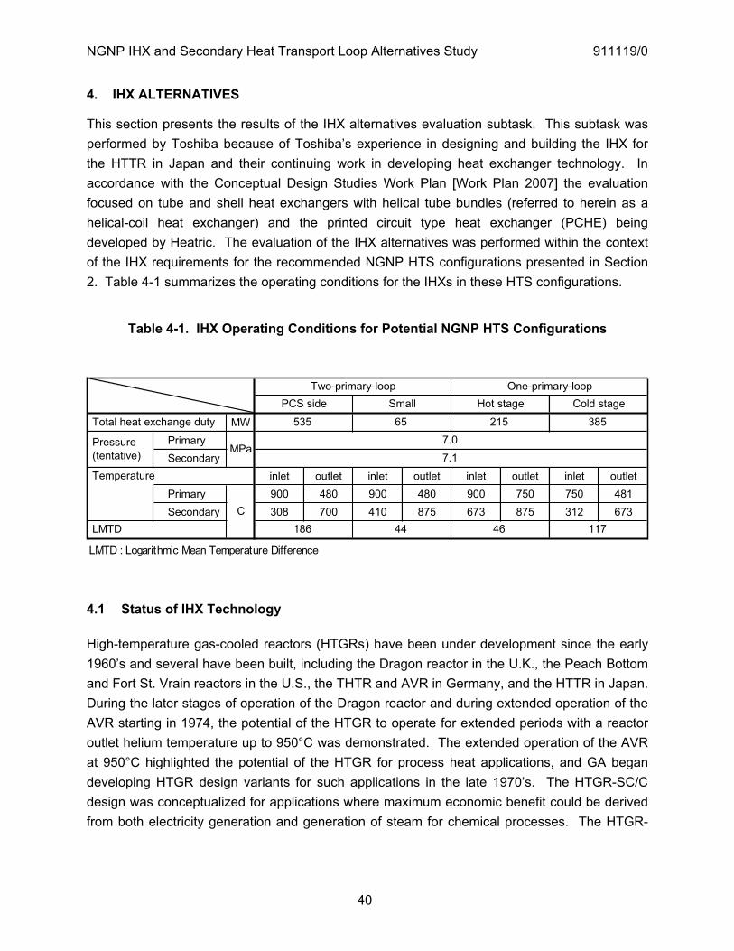
NGNP IHX and Secondary Heat Transport Loop Alternatives Study 911119/0
40
4. IHX ALTERNATIVES
This section presents the results of the IHX alternatives evaluation subtask. This subtask was performed by Toshiba because of Toshiba’s experience in designing and building the IHX for the HTTR in Japan and their continuing work in developing heat exchanger technology. In accordance with the Conceptual Design Studies Work Plan [Work Plan 2007] the evaluation focused on tube and shell heat exchangers with helical tube bundles (referred to herein as a helical-coil heat exchanger) and the printed circuit type heat exchanger (PCHE) being developed by Heatric. The evaluation of the IHX alternatives was performed within the context of the IHX requirements for the recommended NGNP HTS configurations presented in Section 2. Table 4-1 summarizes the operating conditions for the IHXs in these HTS configurations.
Table 4-1. IHX Operating Conditions for Potential NGNP HTS Configurations
MW Primary Secondary
inlet outlet inlet outlet inlet outlet inlet outlet Primary 900 480 900 480 900 750 750 481 Secondary 308 700 410 875 673 875 312 673
Two-primary-loop One-primary-loopPCS side Small Hot stage Cold stage
385 Total heat exchange duty 535 65 215
Pressure (tentative) MPa
7.07.1
Temperature
C LMTD 186 44 46 117
4.1 Status of IHX Technology
High-temperature gas-cooled reactors (HTGRs) have been under development since the early 1960’s and several have been built, including the Dragon reactor in the U.K., the Peach Bottom and Fort St. Vrain reactors in the U.S., the THTR and AVR in Germany, and the HTTR in Japan. During the later stages of operation of the Dragon reactor and during extended operation of the AVR starting in 1974, the potential of the HTGR to operate for extended periods with a reactor outlet helium temperature up to 950°C was demonstrated. The extended operation of the AVR at 950°C highlighted the potential of the HTGR for process heat applications, and GA began developing HTGR design variants for such applications in the late 1970’s. The HTGR-SC/C design was conceptualized for applications where maximum economic benefit could be derived from both electricity generation and generation of steam for chemical processes. The HTGR-
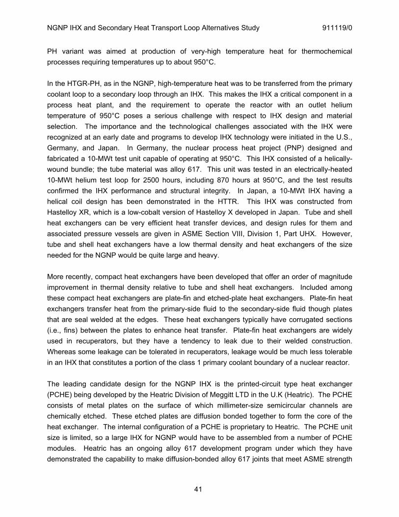
NGNP IHX and Secondary Heat Transport Loop Alternatives Study 911119/0
41
PH variant was aimed at production of very-high temperature heat for thermochemical processes requiring temperatures up to about 950°C.
In the HTGR-PH, as in the NGNP, high-temperature heat was to be transferred from the primary coolant loop to a secondary loop through an IHX. This makes the IHX a critical component in a process heat plant, and the requirement to operate the reactor with an outlet helium temperature of 950°C poses a serious challenge with respect to IHX design and material selection. The importance and the technological challenges associated with the IHX were recognized at an early date and programs to develop IHX technology were initiated in the U.S., Germany, and Japan. In Germany, the nuclear process heat project (PNP) designed and fabricated a 10-MWt test unit capable of operating at 950°C. This IHX consisted of a helically-wound bundle; the tube material was alloy 617. This unit was tested in an electrically-heated 10-MWt helium test loop for 2500 hours, including 870 hours at 950°C, and the test results confirmed the IHX performance and structural integrity. In Japan, a 10-MWt IHX having a helical coil design has been demonstrated in the HTTR. This IHX was constructed from Hastelloy XR, which is a low-cobalt version of Hastelloy X developed in Japan. Tube and shell heat exchangers can be very efficient heat transfer devices, and design rules for them and associated pressure vessels are given in ASME Section VIII, Division 1, Part UHX. However, tube and shell heat exchangers have a low thermal density and heat exchangers of the size needed for the NGNP would be quite large and heavy.
More recently, compact heat exchangers have been developed that offer an order of magnitude improvement in thermal density relative to tube and shell heat exchangers. Included among these compact heat exchangers are plate-fin and etched-plate heat exchangers. Plate-fin heat exchangers transfer heat from the primary-side fluid to the secondary-side fluid though plates that are seal welded at the edges. These heat exchangers typically have corrugated sections (i.e., fins) between the plates to enhance heat transfer. Plate-fin heat exchangers are widely used in recuperators, but they have a tendency to leak due to their welded construction. Whereas some leakage can be tolerated in recuperators, leakage would be much less tolerable in an IHX that constitutes a portion of the class 1 primary coolant boundary of a nuclear reactor.
The leading candidate design for the NGNP IHX is the printed-circuit type heat exchanger (PCHE) being developed by the Heatric Division of Meggitt LTD in the U.K (Heatric). The PCHE consists of metal plates on the surface of which millimeter-size semicircular channels are chemically etched. These etched plates are diffusion bonded together to form the core of the heat exchanger. The internal configuration of a PCHE is proprietary to Heatric. The PCHE unit size is limited, so a large IHX for NGNP would have to be assembled from a number of PCHE modules. Heatric has an ongoing alloy 617 development program under which they have demonstrated the capability to make diffusion-bonded alloy 617 joints that meet ASME strength
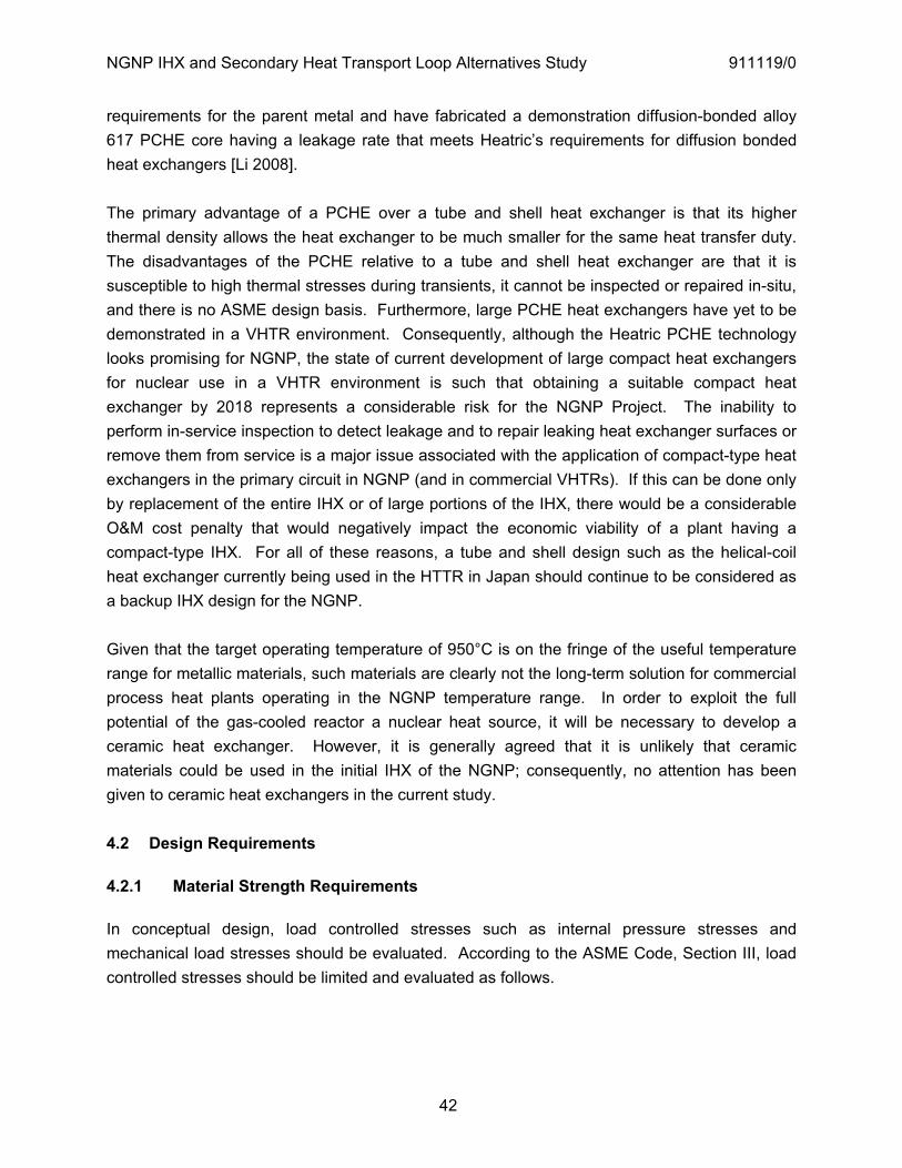
NGNP IHX and Secondary Heat Transport Loop Alternatives Study 911119/0
42
requirements for the parent metal and have fabricated a demonstration diffusion-bonded alloy 617 PCHE core having a leakage rate that meets Heatric’s requirements for diffusion bonded heat exchangers [Li 2008].
The primary advantage of a PCHE over a tube and shell heat exchanger is that its higher thermal density allows the heat exchanger to be much smaller for the same heat transfer duty. The disadvantages of the PCHE relative to a tube and shell heat exchanger are that it is susceptible to high thermal stresses during transients, it cannot be inspected or repaired in-situ, and there is no ASME design basis. Furthermore, large PCHE heat exchangers have yet to be demonstrated in a VHTR environment. Consequently, although the Heatric PCHE technology looks promising for NGNP, the state of current development of large compact heat exchangers for nuclear use in a VHTR environment is such that obtaining a suitable compact heat exchanger by 2018 represents a considerable risk for the NGNP Project. The inability to perform in-service inspection to detect leakage and to repair leaking heat exchanger surfaces or remove them from service is a major issue associated with the application of compact-type heat exchangers in the primary circuit in NGNP (and in commercial VHTRs). If this can be done only by replacement of the entire IHX or of large portions of the IHX, there would be a considerable O&M cost penalty that would negatively impact the economic viability of a plant having a compact-type IHX. For all of these reasons, a tube and shell design such as the helical-coil heat exchanger currently being used in the HTTR in Japan should continue to be considered as a backup IHX design for the NGNP.
Given that the target operating temperature of 950°C is on the fringe of the useful temperature range for metallic materials, such materials are clearly not the long-term solution for commercial process heat plants operating in the NGNP temperature range. In order to exploit the full potential of the gas-cooled reactor a nuclear heat source, it will be necessary to develop a ceramic heat exchanger. However, it is generally agreed that it is unlikely that ceramic materials could be used in the initial IHX of the NGNP; consequently, no attention has been given to ceramic heat exchangers in the current study.
4.2 Design Requirements
4.2.1 Material Strength Requirements
In conceptual design, load controlled stresses such as internal pressure stresses and mechanical load stresses should be evaluated. According to the ASME Code, Section III, load controlled stresses should be limited and evaluated as follows.
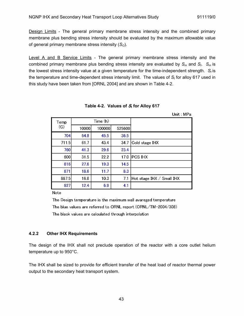
NGNP IHX and Secondary Heat Transport Loop Alternatives Study 911119/0
43
Design Limits - The general primary membrane stress intensity and the combined primary membrane plus bending stress intensity should be evaluated by the maximum allowable value of general primary membrane stress intensity (SO).
Level A and B Service Limits - The general primary membrane stress intensity and the combined primary membrane plus bending stress intensity are evaluated by Sm and St. Sm isthe lowest stress intensity value at a given temperature for the time-independent strength. St isthe temperature and time-dependent stress intensity limit. The values of St for alloy 617 used in this study have been taken from [ORNL 2004] and are shown in Table 4-2.
Table 4-2. Values of St for Alloy 617
4.2.2 Other IHX Requirements
The design of the IHX shall not preclude operation of the reactor with a core outlet helium temperature up to 950°C.
The IHX shall be sized to provide for efficient transfer of the heat load of reactor thermal power output to the secondary heat transport system.

NGNP IHX and Secondary Heat Transport Loop Alternatives Study 911119/0
44
The design lifetime of the IHX shall be 60 years. If material limitations and/or operating conditions preclude an IHX design lifetime of 60 years, the PHTS shall be designed for periodic replacement of the IHX.
Design features shall be included in the PHTS that permit in-service inspection of the IHX during refueling outages.
The IHX shall be removable from the Vessel System as necessary to perform maintenance, repair, or replacement.
4.3 Helical-coil IHX
4.3.1 IHX Design
4.3.1.1 Parallel Primary Loop Configuration
Table 4-3 provides the design conditions for the two helical-coil IHXs in the parallel primary loop configuration presented in Section 2.1.2. The IHX that transfers heat to the PCS is hereafter called the PCS-side IHX, and the 65-MWt IHX that transfers heat to the hydrogen production processes is called the small IHX. It will be necessary to have three PCS-side IHX (and consequently three parallel PCS-side primary loops) due to manufacturing limitations associated with the large size of these heat exchangers. The heat transfer duty for each PCS-side IHX would be 178 MWt.
Table 4-4 and Table 4-5 summarize the results of the design study for the PCS-side IHX and the small IHX, respectively. The tube bundle was sized using the HEATSUP code, which was developed and used for design of the HTTR IHX.
For both the PCS-side IHX and the small IHX, case-4 in Table 4-4 and Table 4-5, respectively, were selected based on manufacturing considerations (i.e., limitation of height of tube bundle) and to keep the helium flow velocity in the center pipe about the same as in the HTTR IHX (~30 m/s) to prevent abnormal flow induced vibration. Figure 4-1 and Figure 4-2 illustrate the conceptual designs of the PCS-side IHX and the small IHX. Unlike the helical-coil IHX design presented in [PCDSR, 2007], these designs do not include a helium circulator as an integral part of the IHX. The estimated weight of the PCS-side IHX is 700 tons with the estimated weights of the vessel and internals being 450 tons and 250 tons, respectively. The estimated weight of the small IHX is 550 tons with the estimated weights of the vessel and internals being 350 tons and 200 tons, respectively.
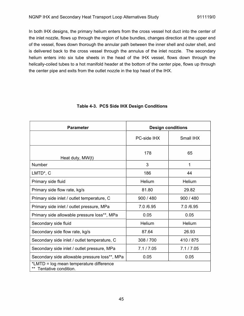
NGNP IHX and Secondary Heat Transport Loop Alternatives Study 911119/0
45
In both IHX designs, the primary helium enters from the cross vessel hot duct into the center of the inlet nozzle, flows up through the region of tube bundles, changes direction at the upper end of the vessel, flows down thorough the annular path between the inner shell and outer shell, and is delivered back to the cross vessel through the annulus of the inlet nozzle. The secondary helium enters into six tube sheets in the head of the IHX vessel, flows down through the helically-coiled tubes to a hot manifold header at the bottom of the center pipe, flows up through the center pipe and exits from the outlet nozzle in the top head of the IHX.
Table 4-3. PCS Side IHX Design Conditions
Parameter Design conditions
PC-side IHX Small IHX
Heat duty, MW(t) 178 65
Number 3 1
LMTD*, C 186 44
Primary side fluid Helium Helium
Primary side flow rate, kg/s 81.80 29.82
Primary side inlet / outlet temperature, C 900 / 480 900 / 480
Primary side inlet / outlet pressure, MPa 7.0 /6.95 7.0 /6.95
Primary side allowable pressure loss**, MPa 0.05 0.05
Secondary side fluid Helium Helium
Secondary side flow rate, kg/s 87.64 26.93
Secondary side inlet / outlet temperature, C 308 / 700 410 / 875
Secondary side inlet / outlet pressure, MPa 7.1 / 7.05 7.1 / 7.05
Secondary side allowable pressure loss**, MPa 0.05 0.05 *LMTD = log mean temperature difference ** Tentative condition.

NGNP IHX and Secondary Heat Transport Loop Alternatives Study 911119/0
46
Table 4-4. HEATSUP Results for PCS-side IHX
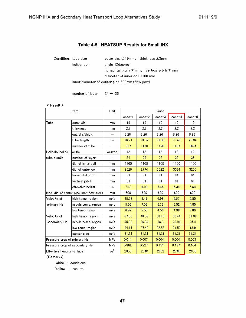
NGNP IHX and Secondary Heat Transport Loop Alternatives Study 911119/0
47
Table 4-5. HEATSUP Results for Small IHX
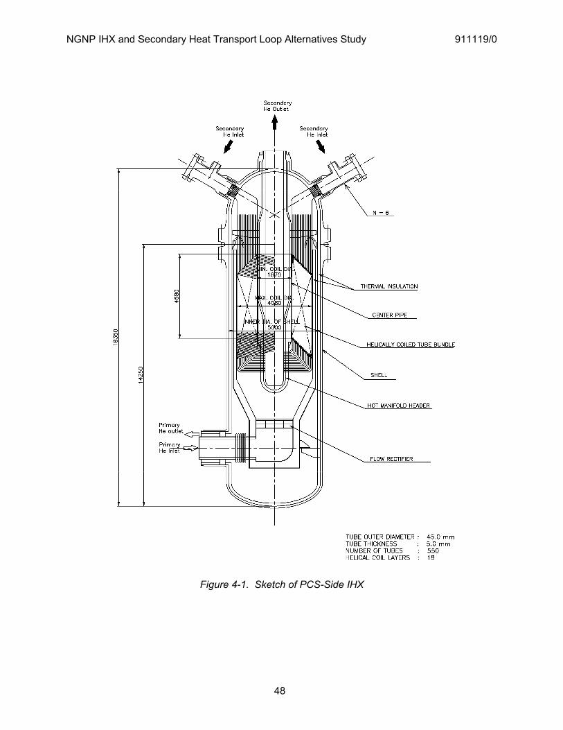
NGNP IHX and Secondary Heat Transport Loop Alternatives Study 911119/0
48
Figure 4-1. Sketch of PCS-Side IHX
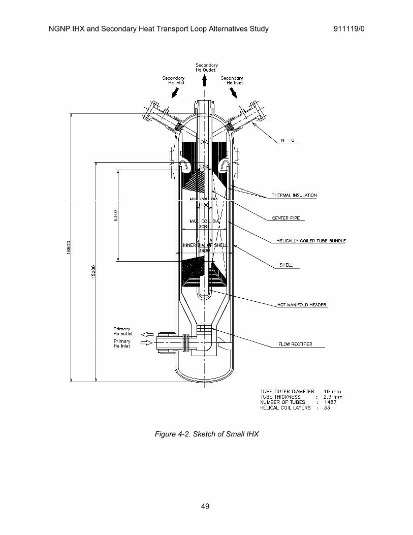
NGNP IHX and Secondary Heat Transport Loop Alternatives Study 911119/0
49
Figure 4-2. Sketch of Small IHX
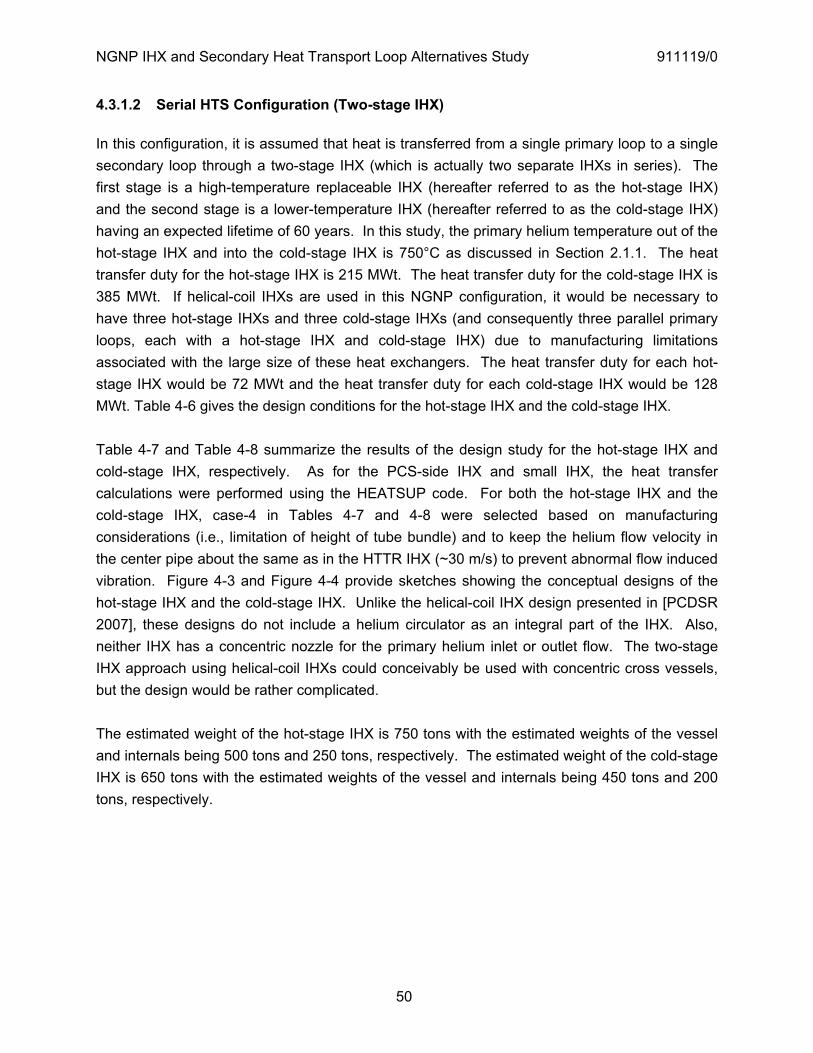
NGNP IHX and Secondary Heat Transport Loop Alternatives Study 911119/0
50
4.3.1.2 Serial HTS Configuration (Two-stage IHX)
In this configuration, it is assumed that heat is transferred from a single primary loop to a single secondary loop through a two-stage IHX (which is actually two separate IHXs in series). The first stage is a high-temperature replaceable IHX (hereafter referred to as the hot-stage IHX) and the second stage is a lower-temperature IHX (hereafter referred to as the cold-stage IHX) having an expected lifetime of 60 years. In this study, the primary helium temperature out of the hot-stage IHX and into the cold-stage IHX is 750°C as discussed in Section 2.1.1. The heat transfer duty for the hot-stage IHX is 215 MWt. The heat transfer duty for the cold-stage IHX is 385 MWt. If helical-coil IHXs are used in this NGNP configuration, it would be necessary to have three hot-stage IHXs and three cold-stage IHXs (and consequently three parallel primary loops, each with a hot-stage IHX and cold-stage IHX) due to manufacturing limitations associated with the large size of these heat exchangers. The heat transfer duty for each hot-stage IHX would be 72 MWt and the heat transfer duty for each cold-stage IHX would be 128 MWt. Table 4-6 gives the design conditions for the hot-stage IHX and the cold-stage IHX.
Table 4-7 and Table 4-8 summarize the results of the design study for the hot-stage IHX and cold-stage IHX, respectively. As for the PCS-side IHX and small IHX, the heat transfer calculations were performed using the HEATSUP code. For both the hot-stage IHX and the cold-stage IHX, case-4 in Tables 4-7 and 4-8 were selected based on manufacturing considerations (i.e., limitation of height of tube bundle) and to keep the helium flow velocity in the center pipe about the same as in the HTTR IHX (~30 m/s) to prevent abnormal flow induced vibration. Figure 4-3 and Figure 4-4 provide sketches showing the conceptual designs of the hot-stage IHX and the cold-stage IHX. Unlike the helical-coil IHX design presented in [PCDSR 2007], these designs do not include a helium circulator as an integral part of the IHX. Also, neither IHX has a concentric nozzle for the primary helium inlet or outlet flow. The two-stage IHX approach using helical-coil IHXs could conceivably be used with concentric cross vessels, but the design would be rather complicated.
The estimated weight of the hot-stage IHX is 750 tons with the estimated weights of the vessel and internals being 500 tons and 250 tons, respectively. The estimated weight of the cold-stage IHX is 650 tons with the estimated weights of the vessel and internals being 450 tons and 200 tons, respectively.

NGNP IHX and Secondary Heat Transport Loop Alternatives Study 911119/0
51
Table 4-6. Hot-stage and Cold-stage IHX Design Conditions
Parameter Design conditions
Hot-stage IHX Cold-stage IHX
Heat duty, MW(t) 72 128
Number 3 3
LMTD*, C 46 117
Primary side fluid Helium Helium
Primary side flow rate, kg/s 91.96 91.96
Primary side inlet / outlet temperature, C 900 / 750 750 / 481
Primary side inlet / outlet pressure, MPa 7.0 /6.95 7.0 /6.95
Primary side allowable pressure loss**, MPa 0.05 0.05
Secondary side fluid Helium Helium
Secondary side flow rate, kg/s 68.44 68.44
Secondary side inlet / outlet temperature, C 673 / 875 312 / 673
Secondary side inlet / outlet pressure, MPa 7.1 / 7.05 7.1 / 7.05 Secondary side allowable pressure loss**, MPa 0.05 0.05
* LMTD = log mean temperature difference. ** Tentative condition.
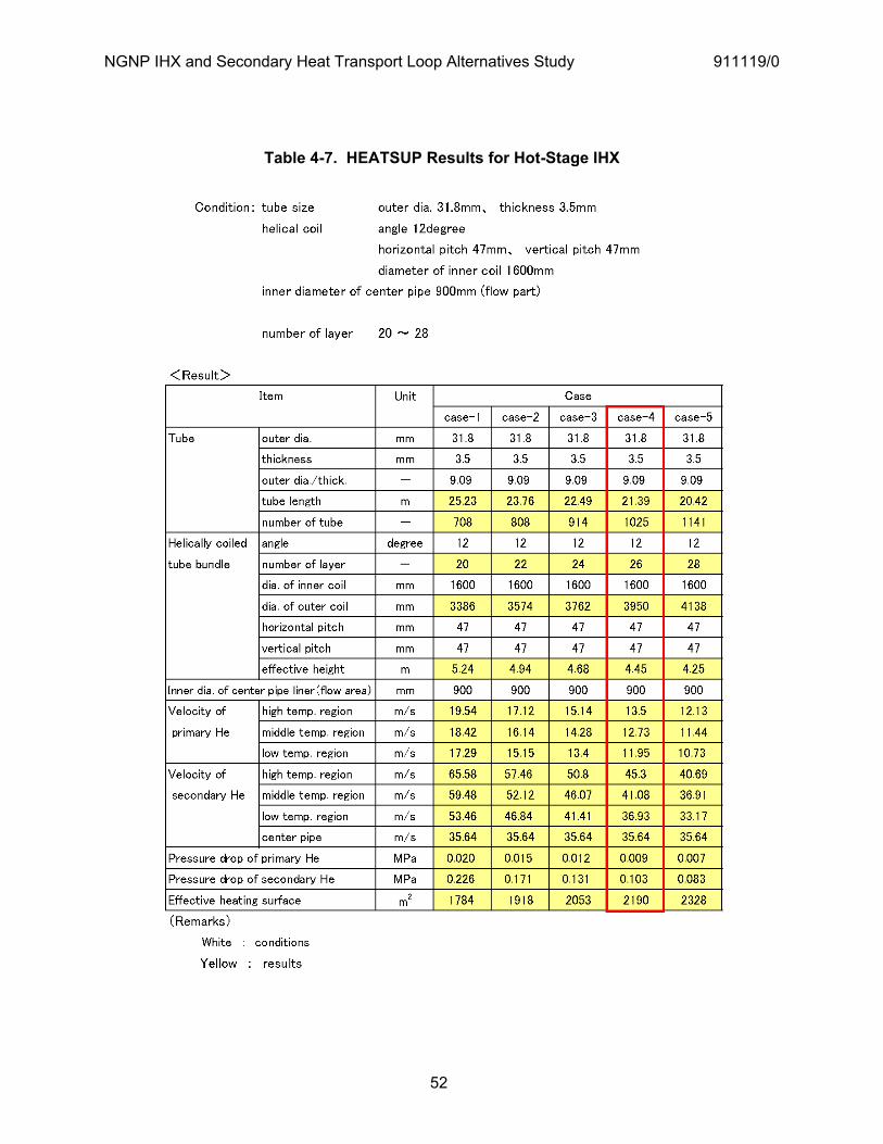
NGNP IHX and Secondary Heat Transport Loop Alternatives Study 911119/0
52
Table 4-7. HEATSUP Results for Hot-Stage IHX
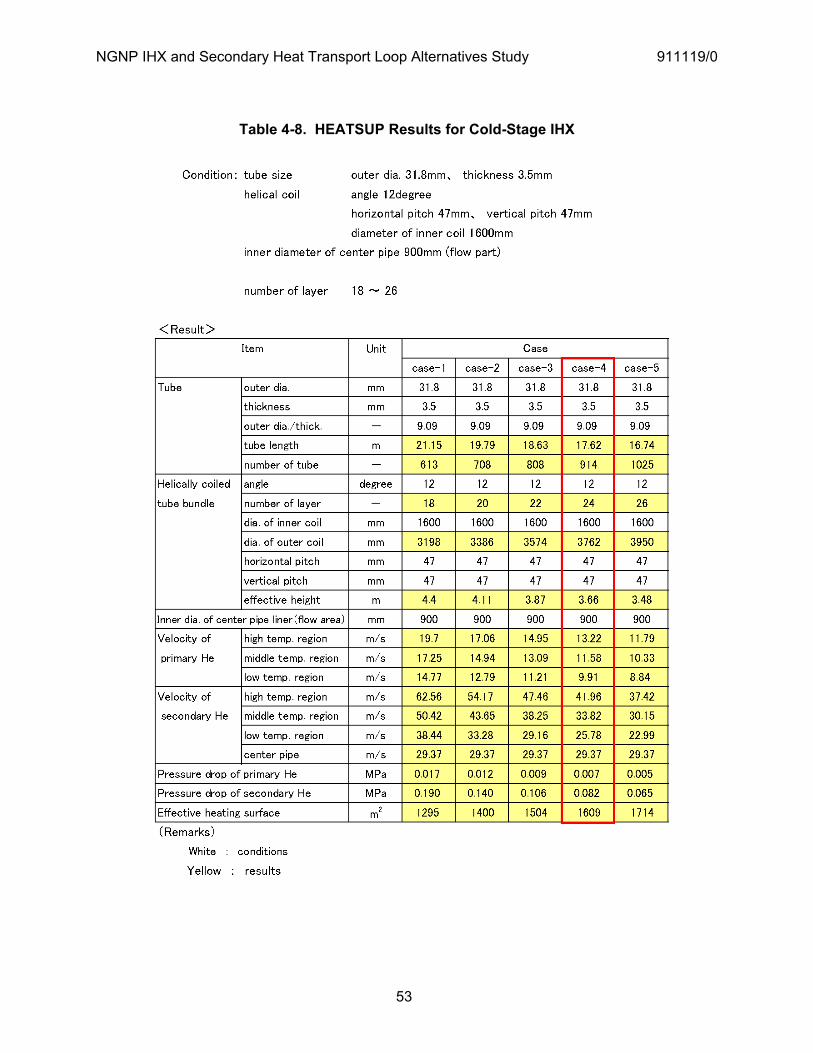
NGNP IHX and Secondary Heat Transport Loop Alternatives Study 911119/0
53
Table 4-8. HEATSUP Results for Cold-Stage IHX

NGNP IHX and Secondary Heat Transport Loop Alternatives Study 911119/0
54
Figure 4-3. Sketch of Hot-Stage IHX
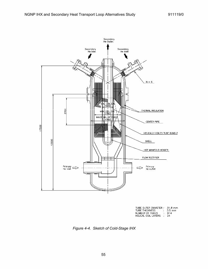
NGNP IHX and Secondary Heat Transport Loop Alternatives Study 911119/0
55
Figure 4-4. Sketch of Cold-Stage IHX
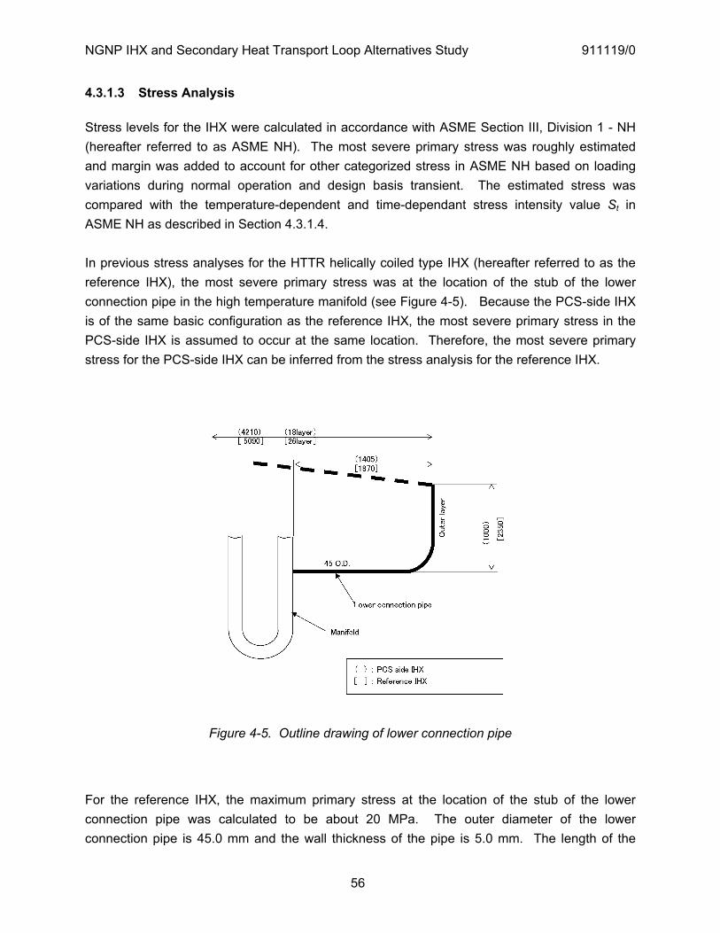
NGNP IHX and Secondary Heat Transport Loop Alternatives Study 911119/0
56
4.3.1.3 Stress Analysis
Stress levels for the IHX were calculated in accordance with ASME Section III, Division 1 - NH (hereafter referred to as ASME NH). The most severe primary stress was roughly estimated and margin was added to account for other categorized stress in ASME NH based on loading variations during normal operation and design basis transient. The estimated stress was compared with the temperature-dependent and time-dependant stress intensity value St in ASME NH as described in Section 4.3.1.4.
In previous stress analyses for the HTTR helically coiled type IHX (hereafter referred to as the reference IHX), the most severe primary stress was at the location of the stub of the lower connection pipe in the high temperature manifold (see Figure 4-5). Because the PCS-side IHX is of the same basic configuration as the reference IHX, the most severe primary stress in the PCS-side IHX is assumed to occur at the same location. Therefore, the most severe primary stress for the PCS-side IHX can be inferred from the stress analysis for the reference IHX.
Figure 4-5. Outline drawing of lower connection pipe
For the reference IHX, the maximum primary stress at the location of the stub of the lower connection pipe was calculated to be about 20 MPa. The outer diameter of the lower connection pipe is 45.0 mm and the wall thickness of the pipe is 5.0 mm. The length of the

NGNP IHX and Secondary Heat Transport Loop Alternatives Study 911119/0
57
lower connection pipe is 4220 mm. The primary stress is mainly dependent on the weight of the lower connection pipe, and because the outer diameter and wall thickness of this pipe in the PCS-side IHX is the same as in the reference IHX, the maximum primary stress for the PCS-side IHX was estimated from the length of the pipes in the two IHXs (see Figure 4-5).
Estimated stress of PCS-side IHX = 20MPa x (2405/4220)2 = 6.5 MPa
Because this value was roughly estimated as the primary stress without detailed analysis, the estimated stress was increased by a factor of 1.5 to add margin for other categorized stresses from loading variations during normal operation and design basis transients. This results in an estimated maximum primary stress of 10 MPa. Consequently, the stress allowable, St, of the material used for the PCS-side IHX should be more than 10 MPa based on the maximum anticipated stress level during normal operation and design basis transients.
4.3.1.4 Structural Specifications
Table 4-9 provides the structural specifications developed for the PCS-side IHX. The same set of structural specifications were developed for the small IHX, the hot-stage IHX, and the cold-stage IHX.
4.3.2 Material Selection
4.3.2.1 Recommended Material
In accordance with the maximum primary stress (10 MPa) calculated for the PCS-side IHX in Section 4.3.1.3, the allowable stress intensity, St, corresponding to 800°C and 60 years must be greater than 10 MPa. Per Table 4-2, the value of St corresponding to 800°C and 60 years for alloy 617 is 17.0 MPA; consequently, alloy 617 is an acceptable material (and is recommended) for the high-temperature internals in the PCS-side IHX.
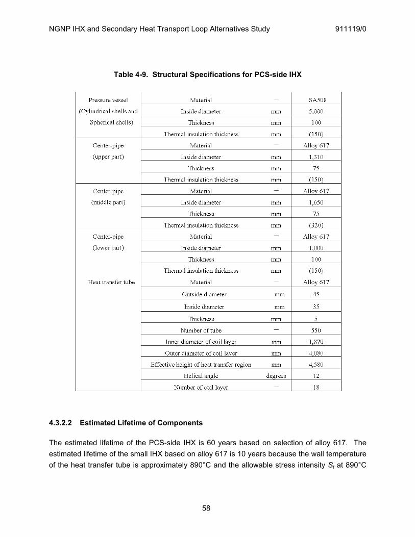
NGNP IHX and Secondary Heat Transport Loop Alternatives Study 911119/0
58
Table 4-9. Structural Specifications for PCS-side IHX
4.3.2.2 Estimated Lifetime of Components
The estimated lifetime of the PCS-side IHX is 60 years based on selection of alloy 617. The estimated lifetime of the small IHX based on alloy 617 is 10 years because the wall temperature of the heat transfer tube is approximately 890°C and the allowable stress intensity St at 890°C
NGNP IHX and Secondary Heat Transport Loop Alternatives Study 911119/0
59
for 10 MPa is limited to 10 years. Consequently, the tube bundle in the small IHX will need to be replaced every 10 years
The estimated lifetime of the tube bundle in the cold-stage IHX is 60 years and the estimated lifetime of the tube bundle in the hot-stage IHX is 10 years. The longer lifetime of the tube bundle in the cold-stage IHX is primarily due to the lower primary-side helium inlet temperature (750°C vs. 900°C in the hot-stage IHX).
4.3.3 Maintainability and Replaceability
4.3.3.1 Tube Plugging
If leakage is detected in a heat transfer tube, the failed heat transfer tube can be closed off by plugging both ends of the tube using the following procedure.
1) A flange is installed on the top end of the center pipe so that the plugging equipment can be inserted into the high temperature manifold from the flange opening at the top end of the center pipe.
2) In the inlet side of the secondary helium gas nozzle, a blank flange is installed on the end of the secondary inlet header so that plugging equipment can be inserted into the heat transfer tube from the opening of the secondary inlet header.
3) The flange of the center pipe and the blank flange of the secondary inlet header are opened and the plugging equipment is inserted from these openings to set plugs into both the inlet and outlet ends of the failed heat transfer tube.
4.3.3.2 Replacement of Tube Bundle
The capability to plug leaking heat transfer tubes in the helical-coil heat exchanger makes it relatively unlikely that tube bundle replacement will be necessary in the PCS-side IHX or the cold-stage IHX, both of which have an estimated lifetime that is equal to the lifetime of the plant (60 years). However, replacement of the tube bundle in the small-IHX and hot-stage IHX is anticipated. Consequently, in the helical-coil IHX design, the heat transfer tube bundle is integrated with the center pipe that is connected to the top head so that the heat transfer tube bundle can be pulled out of the IHX vessel and replaced.
4.3.3.3 In-service Inspection Requirements and Ability to Detect Failures
Required in-service inspections (ISI) can be performed to detect heat transfer tube failure. This is accomplished by installing a flange on the end of the secondary inlet header to allow insertion of an eddy current test (ECT) probe into openings in the heat transfer tubes. The inspection procedure and ETC equipment would be the same as is currently being used for the HTTR IHX.

NGNP IHX and Secondary Heat Transport Loop Alternatives Study 911119/0
60
During development of the ISI equipment for the HTTR IHX, a mock-up test was carried out to verify the performance and detection capability of the equipment. Therefore, if ISI equipment equivalent to that used in the HTTR is used for NGNP, it can be reasonably expected that ISI of heat transfer tubes can be effectively conducted in NGNP. However, confirmatory testing of the specific ECT equipment for an NGNP IHX should be executed.
The ISI necessary for helical-coil type IHX are as follows.
ISI of welded parts in pressure boundary of vessel (UT) ISI of support lug of vessel (MT or PT) ISI of heat transfer tubes (ECT) ISI of high temperature header in welded part of inner pipe (ECT) ISI of general part in welded part of inner pipe (VT by fiber scope through guide tube) ISI of bimetallic weld in upper part of center pipe (RT) ISI of bimetallic weld in low temperature header (UT)
4.3.4 Technology Development Required for 2018 NGNP Startup
Helical coil fabrication techniques were developed for the HTTR IHX for Hastelloy XR tubing having an outer diameter of 31.8 mm and a wall thickness of 3.5 mm. However, because the material (alloy 617) and dimensions (45 mm outer diameter and 5.0 mm wall thickness) of the tubing to be used for the NGNP IHX is different from the tubing used for the HTTR IHX, it will be necessary to develop a coil rolling machine for fabricating the helical coils for the NGNP IHX.
A number of verification tests will be required for the NGNP IHX. These include:
Verification test for rolling fabrication of helical coils Testing to confirm absence of flow induced vibration in the upper and lower connection piping and in the helical coil Verification test of uniform flow by rectifier in a simulated small scale model
The following design verification will also be necessary.
Investigation of structure of support for lower connection pipe which enables to lower load for high temperature manifold Investigation of sliding support structure for IHX Investigation of manufacturing possibility of fabrication large forged material of alloy 617 Investigation of detail arrangement of upper connection pipe and lower connection pipe

NGNP IHX and Secondary Heat Transport Loop Alternatives Study 911119/0
61
4.4 Compact-Type IHX
4.4.1 Basic Design of Printed Circuit Heat Exchanger (PCHE)
It is assumed that the internals of an NGNP compact-type IHX will be of the same basic design as the Heatric modular printed-circuit heat exchanger (PCHE). The PCHE is significantly smaller in size than a standard shell and tube heat exchanger due to the effective use of the heat transfer area, and it can withstand relatively high temperature and pressure with alloy 617. In this study, PCHE modules for NGNP compact-type IHXs were sized using the simple heat transfer analysis and simple stress analysis approach described in [INL 2005], which is summarized below.
Helium Characteristics
The correlations used at GA that closely approximate the data given in [Bolin 2007] are as follows. For thermal conductivity, , the correlations in metric units are given by:
[W/m-K] = 3.32 x 10⁻³ (T [K])0.674
For dynamic viscosity, , the metric correlation is:
[kg/m-s] = 4.24 x 10⁻⁷ (T [K])0.674
Specific heat capacity, cp, for helium is constant at 5.20 [kJ/kg-K].
The density, , of a pure helium coolant is determined by the ideal gas law as shown below in metric units.
KT0792PaPkg/m3
These properties are calculated for the mean temperature between inlet and outlet of PCHE module.
Simple Heat Transfer Analysis
The flow channel size is defined as shown in Figure 4-6. First, the mean flow velocity through the flow channel, u is calculated as:

NGNP IHX and Secondary Heat Transport Loop Alternatives Study 911119/0
62
Amu ,
where A is the total flow area, m is the mass flow rate at the design condition, and is the density at mean temperature between the inlet and outlet of each side of the IHX.
Figure 4-6. Flow Channel Size
The Reynolds number, Re and the Prandtl number, Pr is
eudRe
and
pcPr ,
where ed is the hydraulic dimension, is the thermal conductivity, is the dynamic viscosity,
and pc is the specific heat capacity. These values of these properties correspond to the mean
temperature between the inlet and outlet of each side of the IHX and are assumed to be constant over the length of the module.
For turbulent flow, the heat transfer coefficients are calculated using the Dittus-Boelter correlation, with a leading coefficient of 0.021 for gases and 0.023 for liquids. The Nusselt number, Nu is given by:
4.08.0 PrRe021.0Nu .
dPf
tptf Secondary
Flow Channel
Primary Flow Channel

NGNP IHX and Secondary Heat Transport Loop Alternatives Study 911119/0
63
For laminar flow, the heat transfer coefficients are calculated using the Kay’s correlation for fully developed flow with constant heating rate. The Nusselt number, Nu is given by:
5.08.0 PrRe022.0Nu .
The above equations are applicable for fully developed flow. However, the flow in the PCHE zigzag flow path is likely never fully developed. It is more probable that the flow is more like the flow in the entrance region of a duct or pipe. The use of a correlation that is based on fully developed flow greatly under predicts both the heat transfer coefficient and the pressure drop. As discussed in Section 4.5.4, General Atomics uses a “zigzag” method to predict the size of compact IHXs based on the Heatric PCHE design. The Nusselt number for the “zigzag correlation” is given by
3766.0
PrRe
78.1
edx
Nu ,
where x is the flow length as shown in Figure 4-7.
Figure 4-7. Zigzag flow path
The heat transfer coefficient, h is
edNu
h .
The overall heat transfer coefficient, U , is given by:

NGNP IHX and Secondary Heat Transport Loop Alternatives Study 911119/0
64
21
1211h
dth
Um
p ,
where 1h is the heat transfer coefficient between the primary coolant and the plate, 2h is the
secondary coolant and plate, pt is the thickness of each layer, m is the thermal conductivity of
plate which are calculated by the means shown above.
The effectiveness of PCHE module, is calculated as
cinhinp
houthinhp
TTcmTTcm
min
,
where the subscripts h and c refer to the hot (primary) and cold (secondary) sides of the PCHE module, the subscripts in and out refer to the inlet and outlet ends of the PCHE module, and the subscript min refers to the minimum value for the hot and cold sides.
The required heat transfer area, thA is calculated as
TU
TTcmA cinhinpth
min ,
where T is the log-mean temperature difference.
The heat transfer coefficient h is usually expressed, in compact surface terminology, in terms of the dimensionless, j , or Colburn, factor by
3231 Pr
PrReStNuj ,
where St is the Stanton number,
pcmhSt .
Alternatively, in terms of the hydraulic diameter and flow length,

NGNP IHX and Secondary Heat Transport Loop Alternatives Study 911119/0
65
NLd
j e 32Pr4
,
TTTN oi ,
where L is the flow length and N = NTU (Number of Thermal Units).
The effective heat transfer length per module is the value of long one in the primary and secondary sides such as
che LLL ,max .
Simple Stress Analysis
For primary side flow channel where the external pressure exceeds the internal pressure, the limiting ratio is
ioD
iD
i
o
PPPd
rr
22,
where r is the radius, d is the channel diameter, P is the pressure, and the subscripts i and o refer to the inner and outer surfaces, respectively. For the PCHE module,
po tr
and
2dri ,
where pt is the plate thickness. Therefore, the plate thickness, pt can be approximated as
hcD
hDp PP
Pdt22
,
where the subscripts i and o are replaced into h and c, respectively.
For secondary side flow channel where the internal pressure exceeds the external pressure, the plate thickness, pt is

NGNP IHX and Secondary Heat Transport Loop Alternatives Study 911119/0
66
chD
cDp PP
Pdt22
.
The minimum wall thickness between channels, ft can be approximated as
1P
Pt
D
ff ,
where D is the allowable stress and P is the differential pressure between the hot and cold
sides.
The pitch between channels, fP can be approximated as
Df
PdP 1 .
The flow channel dimensions such as d , ft , fP , and pt are determined to satisfy the above restrictions.
4.4.2 IHX for Parallel Primary Loop Configuration
Table 4-10 provides the design conditions for the two compact IHXs in the parallel primary loop configuration described in Section 2.1.2. The IHX that transfers heat to the PCS is hereafter called the PCS-side IHX, and the 65-MWt IHX that transfers heat to the hydrogen production processes is hereafter called the small IHX. Because of the relatively small size of the compact IHX (relative to the helical-coil IHX discussed in Section 4.3), a single compact PCS-side IHX having a heat transfer duty of 535 MW is feasible for this HTS configuration.
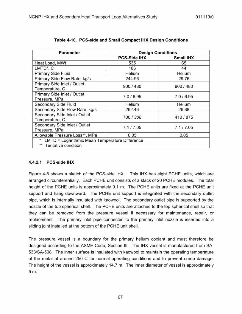
NGNP IHX and Secondary Heat Transport Loop Alternatives Study 911119/0
67
Table 4-10. PCS-side and Small Compact IHX Design Conditions
Parameter Design Conditions PCS-Side IHX Small IHX
Heat Load, MWt 535 65 LMTD*, C 186 44 Primary Side Fluid Helium Helium Primary Side Flow Rate, kg/s 244.96 29.76 Primary Side Inlet / Outlet Temperature, C 900 / 480 900 / 480
Primary Side Inlet / Outlet Pressure, MPa 7.0 / 6.95 7.0 / 6.95
Secondary Side Fluid Helium Helium Secondary Side Flow Rate, kg/s 262.46 26.88 Secondary Side Inlet / Outlet Temperature, C 700 / 308 410 / 875
Secondary Side Inlet / Outlet Pressure, MPa 7.1 / 7.05 7.1 / 7.05
Allowable Pressure Loss**, MPa 0.05 0.05 * LMTD = Logarithmic Mean Temperature Difference ** Tentative condition
4.4.2.1 PCS-side IHX
Figure 4-8 shows a sketch of the PCS-side IHX. This IHX has eight PCHE units, which are arranged circumferentially. Each PCHE unit consists of a stack of 20 PCHE modules. The total height of the PCHE units is approximately 9.1 m. The PCHE units are fixed at the PCHE unit support and hang downward. The PCHE unit support is integrated with the secondary outlet pipe, which is internally insulated with kaowool. The secondary outlet pipe is supported by the nozzle of the top spherical shell. The PCHE units are attached to the top spherical shell so that they can be removed from the pressure vessel if necessary for maintenance, repair, or replacement. The primary inlet pipe connected to the primary inlet nozzle is inserted into a sliding joint installed at the bottom of the PCHE unit shell.
The pressure vessel is a boundary for the primary helium coolant and must therefore be designed according to the ASME Code, Section III. The IHX vessel is manufactured from SA-533/SA-508. The inner surface is insulated with kaowool to maintain the operating temperature of the metal at around 250°C for normal operating conditions and to prevent creep damage. The height of the vessel is approximately 14.7 m. The inner diameter of vessel is approximately 5 m.
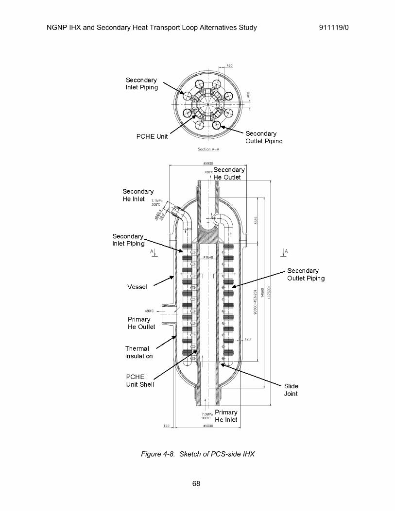
NGNP IHX and Secondary Heat Transport Loop Alternatives Study 911119/0
68
Figure 4-8. Sketch of PCS-side IHX

NGNP IHX and Secondary Heat Transport Loop Alternatives Study 911119/0
69
The primary coolant at 900°C and 7.0 MPa is transported into the PCHE unit shell and goes through the PCHE units to the pressure vessel. Heat is transferred from the primary coolant to the secondary coolant and the temperature of the primary coolant is reduced to 480°C. The primary coolant exits the IHX through the primary outlet nozzle and returns to the reactor vessel via the outer annular flow path of the concentric cross vessel.
On the secondary side of the IHX, the secondary coolant at 308°C and 7.1 MPa flows into the inside of the IHX through the four inlet nozzles installed at the top spherical shell, goes through the secondary inlet piping, and is transported up to the inlet plenum attached to the side of PCHE units. The secondary coolant is heated up to 700°C through the PCHE units, goes out the outlet plenum, and goes upward in the outlet piping, which is insulated internally. The heated secondary coolant is collected in the secondary outlet header and is transported through the secondary loop piping to the steam generator.
Because the thermal expansion between the secondary inlet piping and the PCHE units is different, a thermal expansion absorber is assembled in the secondary inlet piping.
4.4.2.2 Small IHX
Figure 4-9 shows a sketch of the small IHX. The configuration of the small IHX is somewhat different than that of the PCS-side IHX. This IHX has six PCHE units, which are arranged circumferentially. Each PCHE unit consists of a stack of 6 PCHE modules. The total height of the PCHE units is approximately 2.7 m. The PCHE units are attached to the top spherical shell so that they can be removed from the pressure vessel if necessary for maintenance, repair, or replacement.
The pressure vessel is a boundary for the primary helium coolant and must therefore be designed according to the ASME Code, Section III. The IHX vessel is manufactured from SA-533/SA-508. The inner surface is insulated with kaowool to maintain the operating temperature of the metal at around 250°C for normal operating conditions and to prevent creep damage. The height of the vessel is approximately 14.7 m. The inner diameter of vessel is approximately 4 m. In the design shown in Figure 4-10, there is space available in the lower part of the vessel for a helium circulator and the following description assumes inclusion of the circulator.

NGNP IHX and Secondary Heat Transport Loop Alternatives Study 911119/0
70
Figure 4-9. Sketch of small compact IHX
NGNP IHX and Secondary Heat Transport Loop Alternatives Study 911119/0
71
The primary coolant flows through the RV – IHX hot duct and upward into the bottom of the PCHE unit shell. Within the IHX vessel, the hot duct bends and inserts into a sliding joint at the bottom of the PCHE unit shell. The primary coolant at 900°C and 7.0 MPa flows upward through the PCHE units. Heat is transferred from the primary coolant to the secondary HTS helium in the PCHE units. The temperature of the primary coolant drops to 480°C and the coolant descends downward in the IHX and is carried to the helium circulator. The primary coolant is pressurized by the helium circulator, goes upward between the pressure vessel and shroud, and is transported through the annulus between the hot duct and cross-vessel to the RPV.
On the secondary side, the secondary HTS helium enters at 410°C and 7.1 MPa, flows into the inside of the IHX through the 6 inlet nozzles installed at the top spherical shell, goes through the piping, and is transported up to the plenum of the PCHE units. The helium flows through the PCHE unit where it heats up to 875°C, goes through the internally insulated piping, collects in the secondary outlet header, and is transported to the hydrogen production plants by the secondary HTS circulator. Kaowool is used as the thermal insulation for the piping. The wall temperature of the IHX piping and secondary piping is essentially equalized by the thickness of thermal insulation; consequently, a thermal expansion absorber is not needed in the secondary inlet piping.
4.4.3 IHX for Serial HTS Configuration
In this configuration, it is assumed that heat is transferred from the single primary loop to the single secondary loop through a two-stage IHX (which is actually two separate IHX in series). The first stage is a high-temperature replaceable IHX (hereafter referred to as the hot-stage IHX) and the second stage is a lower-temperature IHX (hereafter referred to as the cold-stage IHX) having an expected lifetime of 60 years. In this study, the boundary of the primary helium temperature between the hot-stage IHX and cold-stage IHX is 750°C as discussed in Section 2.1.1. The heat transfer duty for the hot-stage IHX is 215 MWt. The heat transfer duty for the cold-stage IHX is 385 MWt. Table 4-11 provides the design conditions for the hot-stage compact IHX and cold-stage compact IHX in the serial HTS configuration.
4.4.3.1 Hot stage IHX
The conceptual design of the hot-stage IHX is essentially the same as that of the PCS-side IHX shown in Figure 4-8. This IHX has eight PCHE units, which are arranged circumferentially. Each PCHE unit consists of a stack of 24 PCHE modules. The total height of the PCHE units is approximately 10.9 m. The height of the vessel is approximately 16.5 m. The inner diameter of the vessel is about 5m.
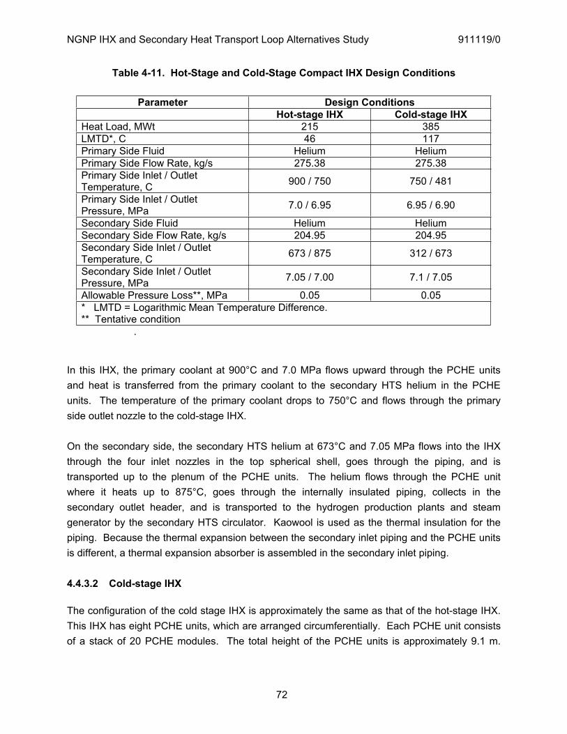
NGNP IHX and Secondary Heat Transport Loop Alternatives Study 911119/0
72
Table 4-11. Hot-Stage and Cold-Stage Compact IHX Design Conditions
Parameter Design Conditions Hot-stage IHX Cold-stage IHX
Heat Load, MWt 215 385 LMTD*, C 46 117 Primary Side Fluid Helium Helium Primary Side Flow Rate, kg/s 275.38 275.38 Primary Side Inlet / Outlet Temperature, C 900 / 750 750 / 481
Primary Side Inlet / Outlet Pressure, MPa 7.0 / 6.95 6.95 / 6.90
Secondary Side Fluid Helium Helium Secondary Side Flow Rate, kg/s 204.95 204.95 Secondary Side Inlet / Outlet Temperature, C 673 / 875 312 / 673
Secondary Side Inlet / Outlet Pressure, MPa 7.05 / 7.00 7.1 / 7.05
Allowable Pressure Loss**, MPa 0.05 0.05 * LMTD = Logarithmic Mean Temperature Difference. ** Tentative condition
.
In this IHX, the primary coolant at 900°C and 7.0 MPa flows upward through the PCHE units and heat is transferred from the primary coolant to the secondary HTS helium in the PCHE units. The temperature of the primary coolant drops to 750°C and flows through the primary side outlet nozzle to the cold-stage IHX.
On the secondary side, the secondary HTS helium at 673°C and 7.05 MPa flows into the IHX through the four inlet nozzles in the top spherical shell, goes through the piping, and is transported up to the plenum of the PCHE units. The helium flows through the PCHE unit where it heats up to 875°C, goes through the internally insulated piping, collects in the secondary outlet header, and is transported to the hydrogen production plants and steam generator by the secondary HTS circulator. Kaowool is used as the thermal insulation for the piping. Because the thermal expansion between the secondary inlet piping and the PCHE units is different, a thermal expansion absorber is assembled in the secondary inlet piping.
4.4.3.2 Cold-stage IHX
The configuration of the cold stage IHX is approximately the same as that of the hot-stage IHX. This IHX has eight PCHE units, which are arranged circumferentially. Each PCHE unit consists of a stack of 20 PCHE modules. The total height of the PCHE units is approximately 9.1 m.

NGNP IHX and Secondary Heat Transport Loop Alternatives Study 911119/0
73
The height of the vessel is approximately 14.7 m. The inner diameter of the vessel is about 5m.
The primary coolant enters the IHX at 750°C and 6.95 MPa, is transported to the PCHE unit shell, and flows through the PCHE units to the pressure vessel. The primary helium drops to 481°C and flows through the primary side outlet nozzle and is returned to the reactor vessel.
On the secondary side, the secondary HTS helium at 312°C and 7.1 MPa flows into the IHX through the four inlet nozzles in the top spherical shell, goes through the secondary inlet piping, and is transported up to the plenum attached to the sides of the PCHE units. The helium flows through the PCHE unit where it heats up to 673°C, goes through the internally insulated piping, collects in the secondary outlet header, and is transported to the hot stage IHX. Because the thermal expansion between the secondary inlet piping and the PCHE units is different, a thermal expansion absorber is assembled in the secondary inlet piping.
4.4.4 Thermal Insulation
Kaowool is tentatively selected as the thermal insulation based on the following criteria:
Low thermal conductivity in helium at high temperature High recoverability from compression state Little deterioration with age Low gas release
The Kaowool will be installed inside of the piping and fixed with the liner as shown in Figure 4-10.

NGNP IHX and Secondary Heat Transport Loop Alternatives Study 911119/0
74
Liner Partition Liner Support
Detail B Detail C
PipeThermal Insulation
Liner
Section A-A
Figure 4-10. Illustration of piping thermal insulation installation
4.4.5 IHX Performance
4.4.5.1 Pressure Loss
The pressure loss on the primary and secondary sides of the IHX is roughly estimated as follows. On the primary side, the pressure drop through the PCHE modules was calculated from the inlet nozzle to the outlet nozzle. On the secondary side, the pressure drop was calculated from the secondary inlet nozzle to the secondary outlet header, both of which are mounted to the top spherical shell of the IHX.
The equation for the pressure loss is:
2P
2vdL
ii
e
,
where P is the pressure loss (Pa), is the coefficient of pipe friction, L is the flow channel length (m), d is the equivalent diameter of the flow channel (m), is the loss coefficient, is the helium density (kg/m3), and v is the helium velocity (m/s).
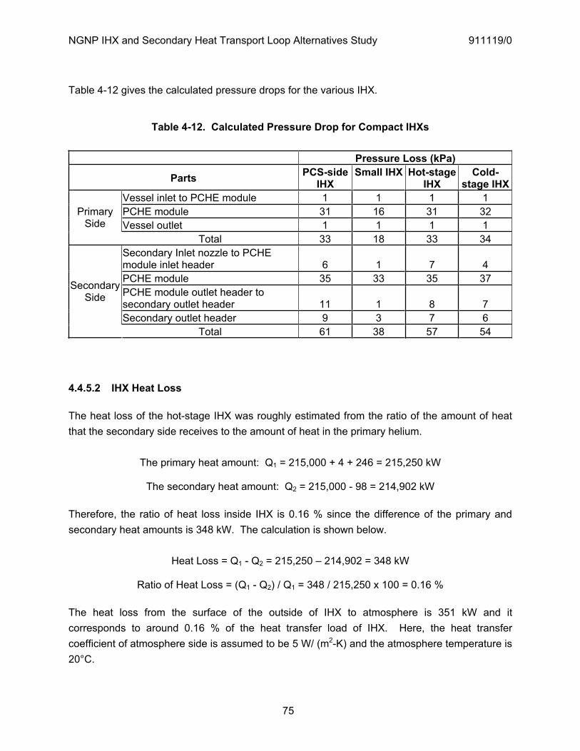
NGNP IHX and Secondary Heat Transport Loop Alternatives Study 911119/0
75
Table 4-12 gives the calculated pressure drops for the various IHX.
Table 4-12. Calculated Pressure Drop for Compact IHXs
Pressure Loss (kPa)
Parts PCS-sideIHX
Small IHX Hot-stage IHX
Cold-stage IHX
Vessel inlet to PCHE module 1 1 1 1 PCHE module 31 16 31 32 Vessel outlet 1 1 1 1
PrimarySide
Total 33 18 33 34 Secondary Inlet nozzle to PCHE module inlet header 6 1 7 4 PCHE module 35 33 35 37 PCHE module outlet header to secondary outlet header 11 1 8 7 Secondary outlet header 9 3 7 6
SecondarySide
Total 61 38 57 54
4.4.5.2 IHX Heat Loss
The heat loss of the hot-stage IHX was roughly estimated from the ratio of the amount of heat that the secondary side receives to the amount of heat in the primary helium.
The primary heat amount: Q1 = 215,000 + 4 + 246 = 215,250 kW
The secondary heat amount: Q2 = 215,000 - 98 = 214,902 kW
Therefore, the ratio of heat loss inside IHX is 0.16 % since the difference of the primary and secondary heat amounts is 348 kW. The calculation is shown below.
Heat Loss = Q1 - Q2 = 215,250 – 214,902 = 348 kW
Ratio of Heat Loss = (Q1 - Q2) / Q1 = 348 / 215,250 x 100 = 0.16 %
The heat loss from the surface of the outside of IHX to atmosphere is 351 kW and it corresponds to around 0.16 % of the heat transfer load of IHX. Here, the heat transfer coefficient of atmosphere side is assumed to be 5 W/ (m2-K) and the atmosphere temperature is 20°C.
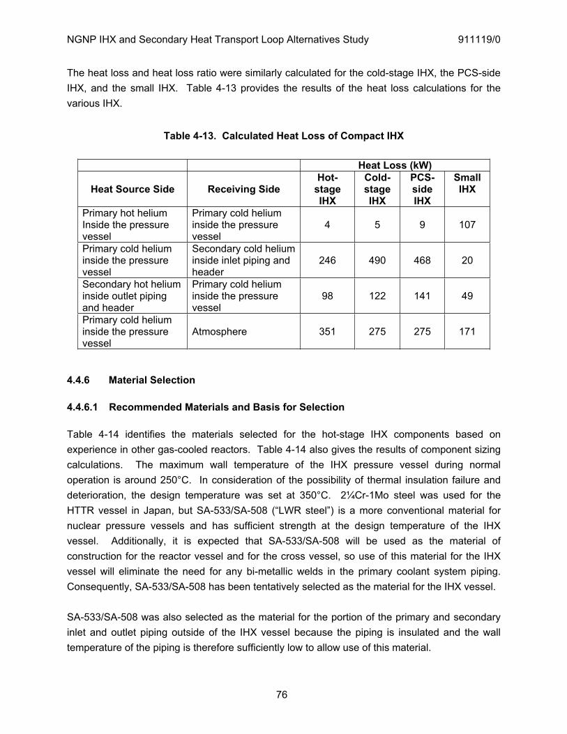
NGNP IHX and Secondary Heat Transport Loop Alternatives Study 911119/0
76
The heat loss and heat loss ratio were similarly calculated for the cold-stage IHX, the PCS-side IHX, and the small IHX. Table 4-13 provides the results of the heat loss calculations for the various IHX.
Table 4-13. Calculated Heat Loss of Compact IHX
Heat Loss (kW)
Heat Source Side Receiving Side Hot-
stageIHX
Cold-stageIHX
PCS-sideIHX
SmallIHX
Primary hot helium Inside the pressure vessel
Primary cold helium inside the pressure vessel
4 5 9 107
Primary cold helium inside the pressure vessel
Secondary cold heliuminside inlet piping and header
246 490 468 20
Secondary hot helium inside outlet piping and header
Primary cold helium inside the pressure vessel
98 122 141 49
Primary cold helium inside the pressure vessel
Atmosphere 351 275 275 171
4.4.6 Material Selection
4.4.6.1 Recommended Materials and Basis for Selection
Table 4-14 identifies the materials selected for the hot-stage IHX components based on experience in other gas-cooled reactors. Table 4-14 also gives the results of component sizing calculations. The maximum wall temperature of the IHX pressure vessel during normal operation is around 250°C. In consideration of the possibility of thermal insulation failure and deterioration, the design temperature was set at 350°C. 2¼Cr-1Mo steel was used for the HTTR vessel in Japan, but SA-533/SA-508 (“LWR steel”) is a more conventional material for nuclear pressure vessels and has sufficient strength at the design temperature of the IHX vessel. Additionally, it is expected that SA-533/SA-508 will be used as the material of construction for the reactor vessel and for the cross vessel, so use of this material for the IHX vessel will eliminate the need for any bi-metallic welds in the primary coolant system piping. Consequently, SA-533/SA-508 has been tentatively selected as the material for the IHX vessel.
SA-533/SA-508 was also selected as the material for the portion of the primary and secondary inlet and outlet piping outside of the IHX vessel because the piping is insulated and the wall temperature of the piping is therefore sufficiently low to allow use of this material.
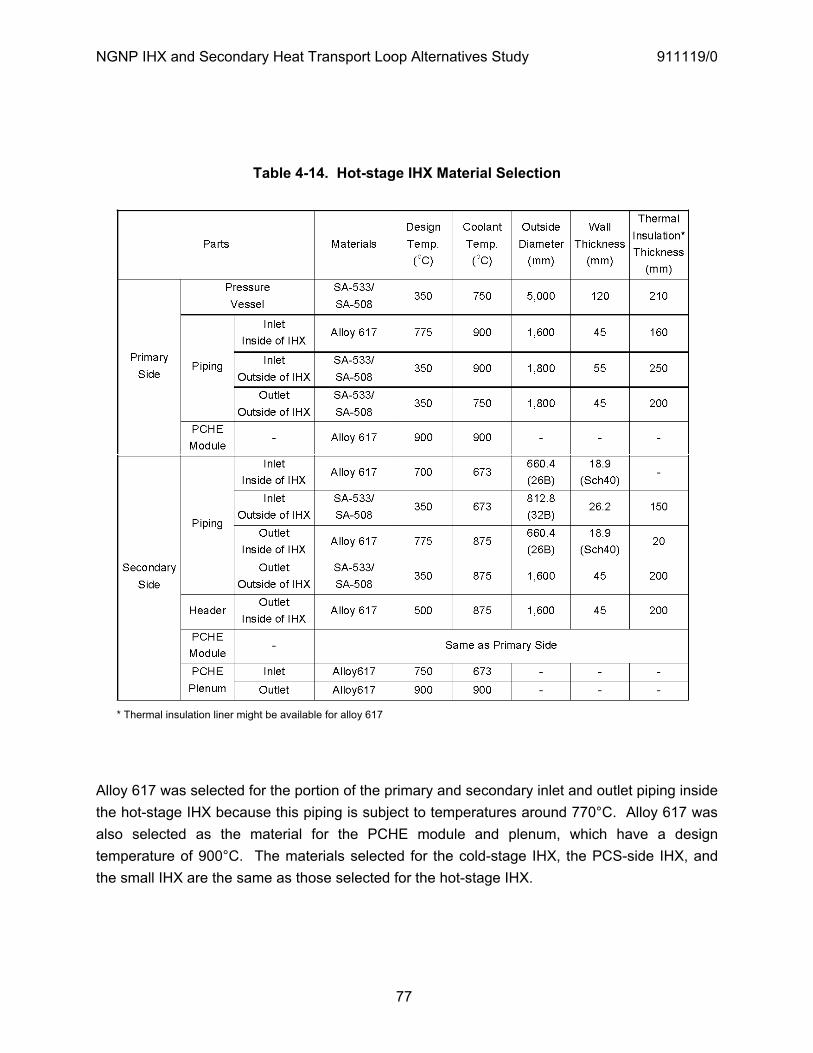
NGNP IHX and Secondary Heat Transport Loop Alternatives Study 911119/0
77
Table 4-14. Hot-stage IHX Material Selection
* Thermal insulation liner might be available for alloy 617
Alloy 617 was selected for the portion of the primary and secondary inlet and outlet piping inside the hot-stage IHX because this piping is subject to temperatures around 770°C. Alloy 617 was also selected as the material for the PCHE module and plenum, which have a design temperature of 900°C. The materials selected for the cold-stage IHX, the PCS-side IHX, and the small IHX are the same as those selected for the hot-stage IHX.

NGNP IHX and Secondary Heat Transport Loop Alternatives Study 911119/0
78
4.4.6.2 Estimated Lifetime of Components
Each type of stress for a flow channel of a PCHE module was calculated based on the equations in Section 4.4.1.
(1) Maximum tangential stress, t :
For the primary side where the external pressure exceeds the internal pressure,
iot
it
i
o
PPP
rr
21
1 ,
where po tr , 2dri , MPa71PPi , MPa1.72PPo .
Therefore,
121
11
22 PPP
dt
t
tp , and
12
222
1122
1 dtPPPdt
p
pt .
For the secondary side where the internal pressure exceeds the external pressure,
oit
ot
i
o
PPP
rr
22
2 ,
where po tr , 2dri , MPa71PPi , MPa1.72PPo .
Therefore,
212
22
22 PPP
dt
t
tp , and
12
222
2212
2 dtPPPdt
p
pt .
The maximum calculated primary side tangential stress was 8 N/mm2 and the maximum calculated secondary side tangential stress was 7 N/mm2.

NGNP IHX and Secondary Heat Transport Loop Alternatives Study 911119/0
79
(2) Stress in terms of the wall thickness between channels, w :
1PP
tw
ff , and
PtP
f
fw 1 ,
where MPa1.012 PPP . The maximum calculated stress w was 1 N/mm2.
(3) Stress in terms of pitch-to-diameter ratio, p :
p
f PdP
1 , and
1dPP
fp ,
where MPa1.012 PPP . The maximum calculated stress p was 1 N/mm2.
The stress can be evaluated using the time-dependent allowable stress, St, for alloy 617 given in [ORNL 2004] for the maximum metal temperature of the PCHE module. The time-dependent allowable stress, St, at 750°C, 875°C, and 900°C is interpolated as shown in Table 4-15.
As described above, the maximum calculated stress for the PCHE module was 8 N/mm2. For the hot-stage IHX, the PCS-side IHX, and the small IHX, the lifetime of the PCHE module at 900°C is approximately 20 years because the allowable stress is 9.2 N/mm2 at 100,000 hours and 6.1 N/mm2 at 525,600 hours. For the maximum secondary temperature of the hot-stage IHX (875°C), the stress is 7 N/mm2 and the lifetime was estimated to be 60 years. For the cold-stage IHX, the lifetime of PCHE module at 750°C is above 60 years.
In order to archive the 60 years lifetime at 900°C, it is necessary to reduce the absolute pressure to 5 MPa.
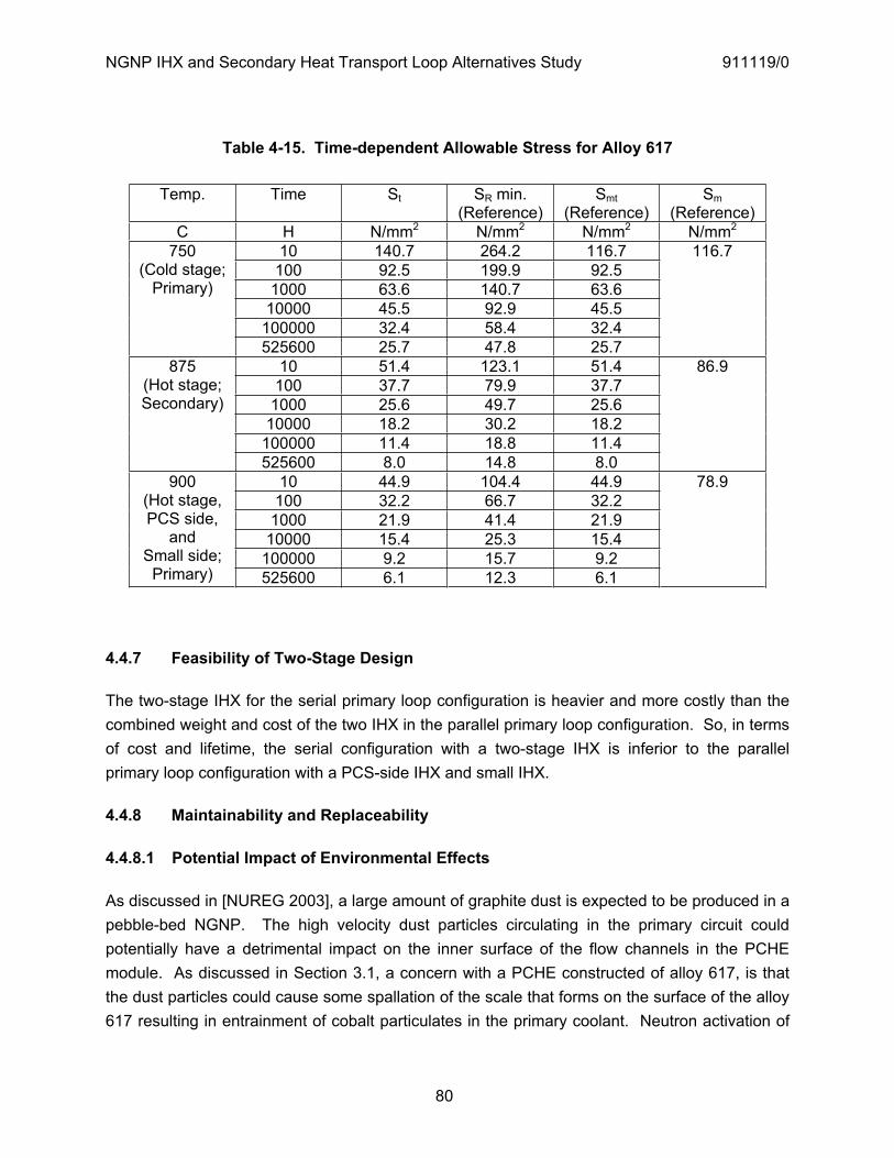
NGNP IHX and Secondary Heat Transport Loop Alternatives Study 911119/0
80
Table 4-15. Time-dependent Allowable Stress for Alloy 617
Temp. Time St SR min. (Reference)
Smt(Reference)
Sm(Reference)
C H N/mm2 N/mm2 N/mm2 N/mm2
10 140.7 264.2 116.7 100 92.5 199.9 92.5
1000 63.6 140.7 63.6 10000 45.5 92.9 45.5
100000 32.4 58.4 32.4
750(Cold stage;
Primary)
525600 25.7 47.8 25.7
116.7
10 51.4 123.1 51.4 100 37.7 79.9 37.7
1000 25.6 49.7 25.6 10000 18.2 30.2 18.2
100000 11.4 18.8 11.4
875(Hot stage; Secondary)
525600 8.0 14.8 8.0
86.9
10 44.9 104.4 44.9 100 32.2 66.7 32.2
1000 21.9 41.4 21.9 10000 15.4 25.3 15.4
100000 9.2 15.7 9.2
900(Hot stage, PCS side,
andSmall side;
Primary) 525600 6.1 12.3 6.1
78.9
4.4.7 Feasibility of Two-Stage Design
The two-stage IHX for the serial primary loop configuration is heavier and more costly than the combined weight and cost of the two IHX in the parallel primary loop configuration. So, in terms of cost and lifetime, the serial configuration with a two-stage IHX is inferior to the parallel primary loop configuration with a PCS-side IHX and small IHX.
4.4.8 Maintainability and Replaceability
4.4.8.1 Potential Impact of Environmental Effects
As discussed in [NUREG 2003], a large amount of graphite dust is expected to be produced in a pebble-bed NGNP. The high velocity dust particles circulating in the primary circuit could potentially have a detrimental impact on the inner surface of the flow channels in the PCHE module. As discussed in Section 3.1, a concern with a PCHE constructed of alloy 617, is that the dust particles could cause some spallation of the scale that forms on the surface of the alloy 617 resulting in entrainment of cobalt particulates in the primary coolant. Neutron activation of

NGNP IHX and Secondary Heat Transport Loop Alternatives Study 911119/0
81
cobalt in the reactor could result in high circulating activity in the primary coolant. Also, the dust particles could potentially cause blockage of the flow channels in the PCHE. However, as discussed in [Hanson 2008], the relatively small amount of circulating dust in a prismatic NGNP poses little hazard to the IHX.
4.4.8.2 In-service Inspection and Ability to Detect Failures
It will likely not be possible to perform in-service inspection (ISI) of PCHEs. Consequently, it would be necessary to continuously monitor the pressure difference between the primary and secondary side of the PCHE.
4.4.8.3 Consequence of Material Failure During Plant Operation
In the event that failure of a PCHE module is detected by monitoring the pressure difference between the primary side and secondary side during plant operation, replacement of the entire PCHE unit will be necessary because it will not be possible to identify the damaged module. In the Toshiba IHX designs, the PCHE units are attached to the top spherical shell of the IHX vessel and can be removed from the vessel.
4.4.9 Technology Development
4.4.9.1 PCHE Module
The PCHE module is used in industrial heat exchangers, but has not been used in nuclear plants. Also, PCHE modules have yet to be built and operated at the service temperatures envisioned for the NGNP IHX. The conventional material for the PCHE module is austenitic stainless steel, but for the NGNP IHX, the application of a higher temperature material such as alloy 617, will be necessary.
In order to extend the PCHE to the service conditions of the NGNP, extensive verification testing will be needed to confirm the design and performance of the PCHE. This testing will include confirmation of:
The PCHE core strength; especially the bonded layer strength, fatigue strength, and corrosion-erosion resistance
Conformance of the design to ASME code and NRC requirements The PCHE core temperature distribution The thermal hydraulic characteristics as a whole IHX

NGNP IHX and Secondary Heat Transport Loop Alternatives Study 911119/0
82
Confirmation of the PCHE core strength. The PCHE core is fabricated by diffusion bonding multiple layers of thin plates. It is necessary to confirm the strength of this diffusion bonded joints. The flow channel etched chemically has corners that are subject to stress concentration. Therefore, it will also be necessary to confirm fatigue strength. In addition, the corrosion-erosion resistance of alloy 617 in an impure helium environment must be confirmed.
Confirmation of conformance to ASME code and NRC requirements. As discussed in Section 3.2, it is assumed that design rules for the PCHE will be codified in either ASME Section III or Section VIII. Once such rules are established, it will be necessary to confirm that the NGNP PCHE design can satisfy these design rules. It will also be necessary to confirm that the in-service performance of the PCHE core can be monitored per NRC requirements.
Confirmation of the PCHE core temperature distribution. For application of the PCHE module to the NGNP IHX, the calculated temperature distribution inside the module must be confirmed by testing.
Confirmation of the thermal hydraulic characteristics as a whole IHX. It is necessary to confirm the flow and temperature distribution of the entire IHX by testing and analysis.
4.4.9.2 Other Components
A slide joint is used to facilitate maintenance and replacement of the PCHE units in the IHX. It is necessary to evaluate the leak rate from the slide joint.
In the compact-type IHX, the PCHE units hang down from the top shell. The large temperature differences can cause deformation of the PCHE modules. The radial support between the vessel and the PCHE unit must be developed. Seismic loads must also be considered in the design.
4.5 Technical Issues
4.5.1 Material Issues
The high-temperature material alternatives for the IHX internals and the issues associated with material selection are discussed in Section 3.1.
4.5.2 Structural Issues
The installation method of the thermal insulation into the small pipe needs to be established Design of the IHX – cross vessel interface
NGNP IHX and Secondary Heat Transport Loop Alternatives Study 911119/0
83
Whether a helium circulator should be installed at the bottom of the IHX vessel. The maintenance needs to be fully considered by a mock-up about the working space,
fabrication methods, and so on The feasibility of the secondary piping and the PCHE unit support need to be confirmed by
structural analysis The lifecycle of IHX is 60 years. The pressure vessel is designed around 250°C to prevent
creep damage, but the internals need to be confirmed It is not possible to perform ISI of the PCHE module as required by ASME Code, Section XI,
Division 2. The PCHE module perhaps should not be part of the primary coolant pressure boundary. In this case, the primary coolant pressure boundary might be considered to extend to the isolation valves in the secondary heat transport system.
The compact type IHX should be monitored for leakage and it would be desirable to test it for insipient failures. However, this cannot be done for the PCHE
The pressure loss of PCHE module is estimated, but the exact value needs to be confirmed by testing
Detailed structural analysis is needed to confirm the IHX designs developed in this study. In particular, the temperature difference between the inlet and outlet of the PCHE module is large and analysis of thermal stresses and distortion are needed
A slide joint is used to enable the maintenance and replacement of the PCHE units. It is necessary to evaluate the leak rate from a slide joint
There is not sufficient data to judge the environmental effect of impure helium on alloy 617. It might be necessary to consider corrosion and erosion in estimating the design lifetime of PCHE modules.
The PCHE module is fabricated by diffusion bonding of many plates. The flow channel has the two corners on the bonding surface. Therefore, fatigue might be lifetime limiting.
4.5.3 System Issues
The IHX will have to be able to withstand pressure transients in either the primary or the secondary HTS. The most frequent anticipated pressure transient would be a loss of the primary cooling system and equalization of the primary system pressure. Accidents would include primary system or secondary system depressurizations, which involve reactor trip, IHX circulation trip, and secondary circulator trip. The secondary HTS will have isolation valves, and the plant instrumentation and control system must include features (such as automatic shutdown of the primary and secondary HTS circulators) that provide protection against propagation of an upset condition in either the reactor or the hydrogen production plant to the other plant.
The secondary loop pressure is assumed to be around 7 MPa. However, it is not clear that it should be higher than the primary system pressure. With the secondary pressure only

NGNP IHX and Secondary Heat Transport Loop Alternatives Study 911119/0
84
slightly higher than the primary, one would have limited means of detecting a leak in the IHX. If the secondary pressure is slightly lower than the primary, then a leak could be detected by radioactivity in the secondary coolant. Having a low pressure in the secondary heat transfer system might also be beneficial from the standpoint of the hydrogen production process heat exchanger.
4.5.4 PCHE Sizing
The Heatric PCHE consists of multi zigzag flow channels of the type shown In Figure 4-11. Various methods of calculating the heat transfer coefficients and pressure drops have been proposed. Hejzlar [Hejzlar 2004] has investigated two different calculation methods for PCHE heat exchangers. These two methods are a zigzag channel method and a sine wave method. INL has proposed using the Dittus-Boleter equation for turbulent flow and a similar equation for laminar flow [INL 2005]. Both of the equations recommended by INL are based on fully developed flow. The flow in the PCHE zigzag flow path is never fully developed. It is probably more like the flow in the entrance region of a duct or pipe. Thus, using a correlation that is based on fully developed flow greatly under predicts both the heat transfer coefficient and the pressure drop. Of the two methods presented [Hejzlar 2004], the zigzag method is the more conservative. The heat transfer predictions of this method fall between the correlations based on fully developed flow and the sine wave model. Thus, GA uses the zigzag method to estimate the size compact based on the Heatric PCHE heat exchanger design. The zigzag correlation is presented below.
Figure 4-11. Zigzag Flow Path in HeatricR PCHE
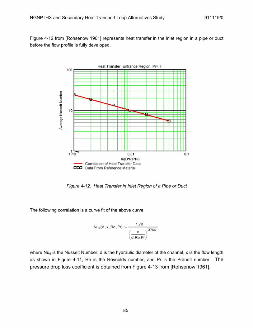
NGNP IHX and Secondary Heat Transport Loop Alternatives Study 911119/0
85
Figure 4-12 from [Rohsenow 1961] represents heat transfer in the inlet region in a pipe or duct before the flow profile is fully developed.
Figure 4-12. Heat Transfer in Inlet Region of a Pipe or Duct
The following correlation is a curve fit of the above curve
where Nud is the Nusselt Number, d is the hydraulic diameter of the channel, x is the flow length as shown in Figure 4-11, Re is the Reynolds number, and Pr is the Prandtl number. The pressure drop loss coefficient is obtained from Figure 4-13 from [Rohsenow 1961].
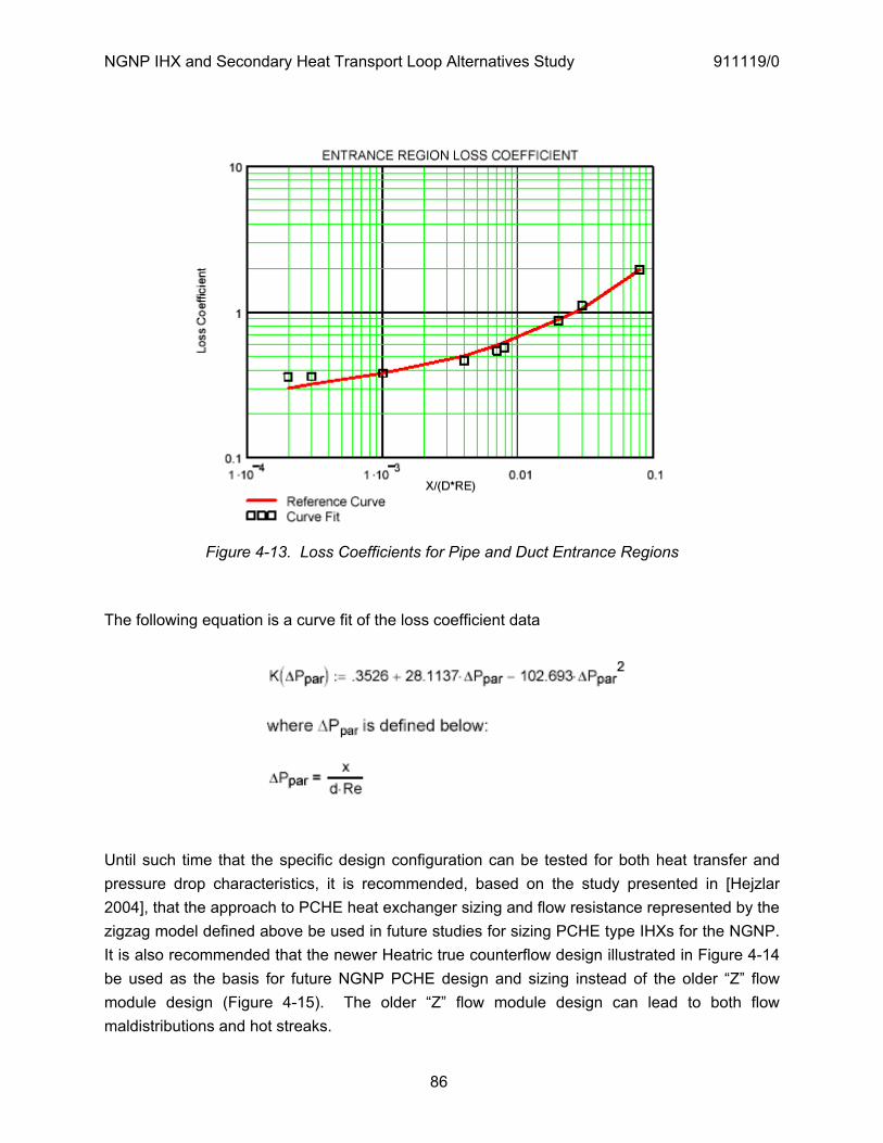
NGNP IHX and Secondary Heat Transport Loop Alternatives Study 911119/0
86
Figure 4-13. Loss Coefficients for Pipe and Duct Entrance Regions
The following equation is a curve fit of the loss coefficient data
Until such time that the specific design configuration can be tested for both heat transfer and pressure drop characteristics, it is recommended, based on the study presented in [Hejzlar 2004], that the approach to PCHE heat exchanger sizing and flow resistance represented by the zigzag model defined above be used in future studies for sizing PCHE type IHXs for the NGNP. It is also recommended that the newer Heatric true counterflow design illustrated in Figure 4-14 be used as the basis for future NGNP PCHE design and sizing instead of the older “Z” flow module design (Figure 4-15). The older “Z” flow module design can lead to both flow maldistributions and hot streaks.
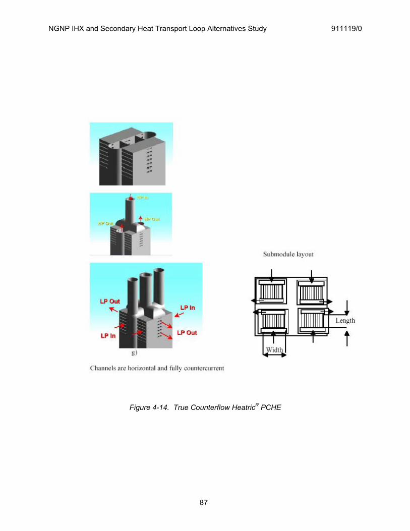
NGNP IHX and Secondary Heat Transport Loop Alternatives Study 911119/0
87
Figure 4-14. True Counterflow HeatricR PCHE
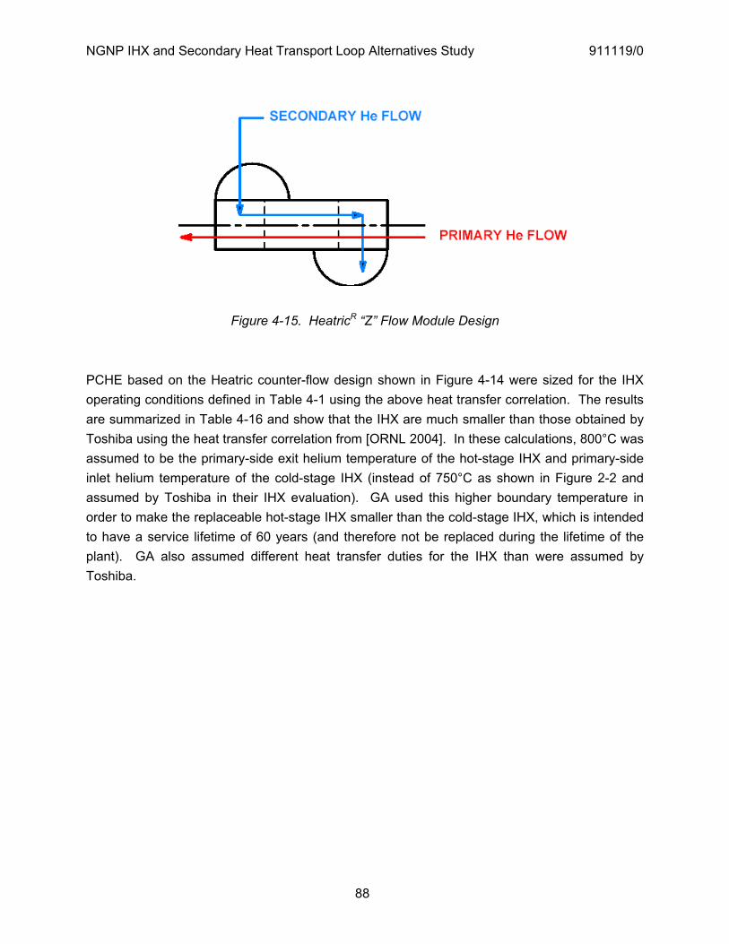
NGNP IHX and Secondary Heat Transport Loop Alternatives Study 911119/0
88
Figure 4-15. HeatricR “Z” Flow Module Design
PCHE based on the Heatric counter-flow design shown in Figure 4-14 were sized for the IHX operating conditions defined in Table 4-1 using the above heat transfer correlation. The results are summarized in Table 4-16 and show that the IHX are much smaller than those obtained by Toshiba using the heat transfer correlation from [ORNL 2004]. In these calculations, 800°C was assumed to be the primary-side exit helium temperature of the hot-stage IHX and primary-side inlet helium temperature of the cold-stage IHX (instead of 750°C as shown in Figure 2-2 and assumed by Toshiba in their IHX evaluation). GA used this higher boundary temperature in order to make the replaceable hot-stage IHX smaller than the cold-stage IHX, which is intended to have a service lifetime of 60 years (and therefore not be replaced during the lifetime of the plant). GA also assumed different heat transfer duties for the IHX than were assumed by Toshiba.
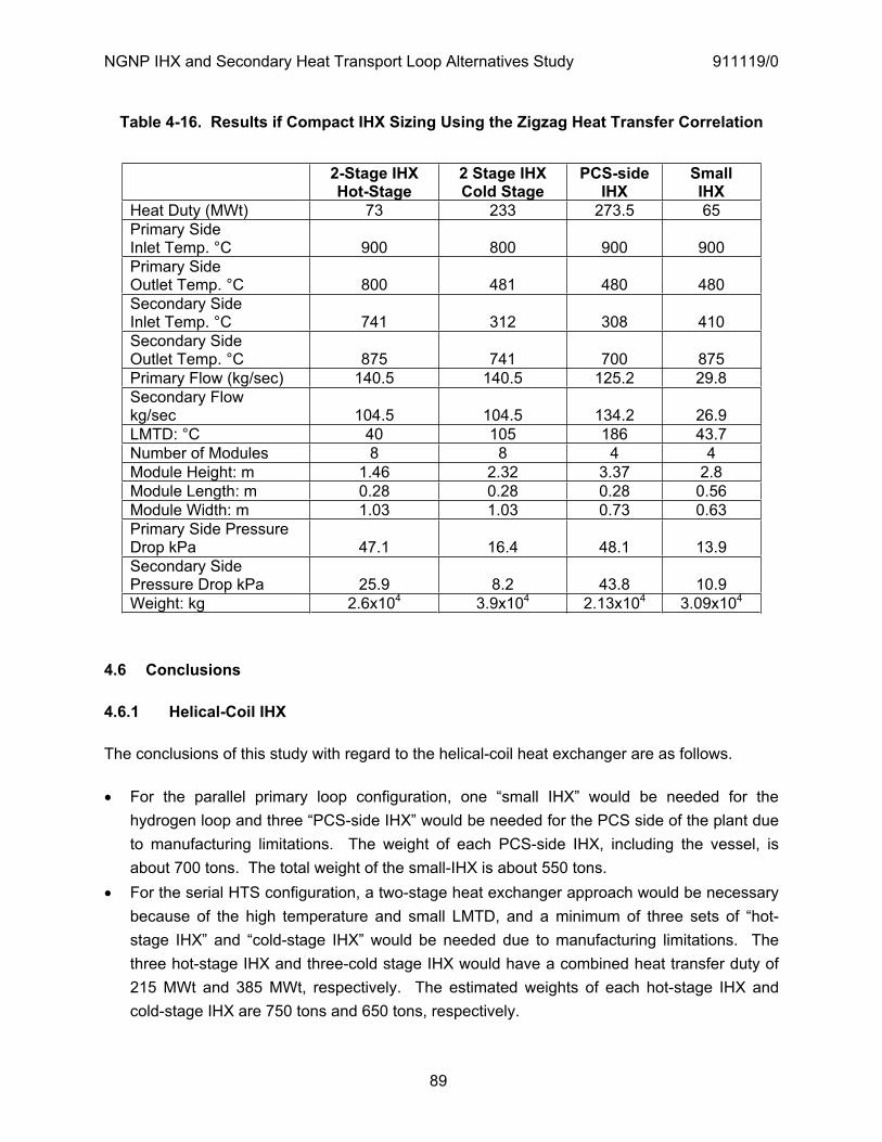
NGNP IHX and Secondary Heat Transport Loop Alternatives Study 911119/0
89
Table 4-16. Results if Compact IHX Sizing Using the Zigzag Heat Transfer Correlation
2-Stage IHX Hot-Stage
2 Stage IHX Cold Stage
PCS-sideIHX
SmallIHX
Heat Duty (MWt) 73 233 273.5 65 Primary Side Inlet Temp. °C 900 800 900 900Primary Side Outlet Temp. °C 800 481 480 480Secondary Side Inlet Temp. °C 741 312 308 410Secondary Side Outlet Temp. °C 875 741 700 875Primary Flow (kg/sec) 140.5 140.5 125.2 29.8 Secondary Flow kg/sec 104.5 104.5 134.2 26.9LMTD: °C 40 105 186 43.7 Number of Modules 8 8 4 4 Module Height: m 1.46 2.32 3.37 2.8 Module Length: m 0.28 0.28 0.28 0.56 Module Width: m 1.03 1.03 0.73 0.63 Primary Side Pressure Drop kPa 47.1 16.4 48.1 13.9Secondary Side Pressure Drop kPa 25.9 8.2 43.8 10.9Weight: kg 2.6x10⁴ 3.9x10⁴ 2.13x10⁴ 3.09x10⁴
4.6 Conclusions
4.6.1 Helical-Coil IHX
The conclusions of this study with regard to the helical-coil heat exchanger are as follows.
For the parallel primary loop configuration, one “small IHX” would be needed for the hydrogen loop and three “PCS-side IHX” would be needed for the PCS side of the plant due to manufacturing limitations. The weight of each PCS-side IHX, including the vessel, is about 700 tons. The total weight of the small-IHX is about 550 tons.
For the serial HTS configuration, a two-stage heat exchanger approach would be necessary because of the high temperature and small LMTD, and a minimum of three sets of “hot-stage IHX” and “cold-stage IHX” would be needed due to manufacturing limitations. The three hot-stage IHX and three-cold stage IHX would have a combined heat transfer duty of 215 MWt and 385 MWt, respectively. The estimated weights of each hot-stage IHX and cold-stage IHX are 750 tons and 650 tons, respectively.
NGNP IHX and Secondary Heat Transport Loop Alternatives Study 911119/0
90
A two-stage helical-coil IHX would complicate use of a cross vessel having a concentric hot duct
Verified procedures are available for plugging leaking tubes. If necessary, the helically-coiled bundles can be removed from the vessel for maintenance, repair, or replacement.
For the small-IHX and the hot-stage IHX, the design lifetime of the helically-coiled bundle is approximately 10 years.
For the PCS-side IHX and the cold-stage IHX, the design lifetime of the helically coiled bundle can be above 60 years.
The parallel primary loop configuration is considered to be superior to the serial HTS configuration from the standpoint of both IHX lifetime and cost.
4.6.2 Compact-Type IHX
The conclusions of this study with regard to the compact-type heat exchanger are as follows.
For the parallel primary loop configuration, one “small IHX” would be needed for the hydrogen loop and one “PCS-side IHX” would be needed. The weight of the PCS-side IHX, including the vessel, is about 610 tons. The total weight of the small-IHX is about 350 tons.
For the serial HTS configuration, a two-stage heat exchanger would be necessary because of the high temperature and small LMTD. Based on Toshiba’s sizing method, one hot-stage IHX and one cold-stage IHX (in separate vessels) would be needed. The weights of the hot-stage IHX and cold-stage IHX, including the vessels, would be about 680 tons and 600 tons, respectively.
A two-stage compact IHX consisting of separate hot-stage and cold-stage IHXs, as proposed by Toshiba, would complicate use of a cross vessel having a concentric hot duct
The PCHE units would not be subject to ISI nor could individual PCHE modules be removed for repair or replacement. However, entire PCHE units comprising a stack of PCHE modules could be removed from the vessel for maintenance, repair, or replacement because the PCHE units are attached at the top spherical shell of IHX.
For the hot-stage IHX, the PCS-side IHX, and the small-IHX, the lifetime of the PCHE modules at 900°C is about 20 years. In order to archive a 60 years lifetime at 900°C, it would be necessary to reduce the primary and secondary HTS pressure to 5 MPa.
For the cold-stage IHX, the design lifetime of the PCHE modules at 750°C can be above 60 years.
The parallel primary loop configuration is considered to be superior to the serial HTS configuration from the standpoint of both IHX lifetime and cost.
NGNP IHX and Secondary Heat Transport Loop Alternatives Study 911119/0
91
5. NRC REGULATIONS AND GUIDANCE POTENTIALLY APPLICABLE TO NGNP
This section documents URS - Washington Division (URS-WD) review and identification of NRC regulations and associated regulatory guidance documents that are considered to be potentially applicable to NGNP prismatic modular reactor (PMR). The term “NGNP” is used throughout this section to refer to the general plant design under consideration.
Each of the two NGNP HTS configurations that have been selected for evaluation in this study (see Figures 2-1 and 2-2) and a third configuration selected for evaluation in the steam generator alternatives study [Labar 2008] were considered in the context of the regulatory criteria addressed herein. Title 10 of the Code of Federal Regulations (10CFR) is the governing set of regulations for licensing domestic nuclear reactors, including Class 103 licenses and certifications for commercial reactors. Therefore, this study is based on a systematic review of 10CFR criteria, to identify those of interest to the design alternatives under consideration.
The review focused on the NGNP reactor vessel (RPV), cross vessel (CV), IHX, and secondary HTS, and the functions performed by these structures, systems, and components (SSCs). However, many of the principles and criteria presented below are applicable to the entire NGNP design. This is critical since NRC regulations (including 10CFR50/52, 10CFR100, and 10CFR20) are based upon assuring the radiological protection of the general public as well as plant workers, successfully achieved by implementing the "defense-in-depth" (DiD) principle.
Current NRC regulations for power reactors are focused on Light-Water Reactor (LWR) designs. As discussed in Section 5.2, 10CFR50.43(e) must be addressed. This will be a complex undertaking, and if the NGNP is not a prototype plant, compliance against 10CFR50.43(e)1, as a minimum will be required. If the NGNP is considered to be a prototype plant, compliance with 10CFR50.43(e)2, which states that the NRC may impose additional requirements on the prototype plant to protect the public and plant staff during the testing period, will be required. Therefore, this review also highlights criteria and potential issues whose resolution may influence ongoing rulemaking and standards development efforts in support of NGNP licensing (e.g., risk-informed and performance based rulemaking via 10CFR53).
A summary of key observations and recommendations is provided in Section 5.3.
NGNP IHX and Secondary Heat Transport Loop Alternatives Study 911119/0
92
5.1 Defense-in-Depth
5.1.1 NRC DiD Policy
As defined in the Commission’s 1999 white paper on risk-informed, performance-based regulation, DID is "...an element of the NRC’s Safety Philosophy that employs successive compensatory measures to prevent accidents or mitigate damage if a malfunction, accident, or naturally-caused event occurs at a nuclear facility. The defense-in-depth philosophy ensures that safety will not be wholly dependent on any single element of the design, construction, maintenance, or operation of a nuclear facility. The net effect of incorporating defense-in-depth into design, construction, maintenance, and operation is that the facility or system in question tends to be more tolerant of failures and external challenges.”
As discussed in SECY-03-0047, "Policy Issues Related to Licensing Non-Light-Water Reactor Designs" dated March 28, 2003, the philosophy of defense-in-depth (DiD) has been a fundamental part of NRC’s regulatory programs since the NRC’s inception. It is the design philosophy reiterated in numerous regulatory documents, including the Safety Goal Policy Statement, the probabilistic risk assessment (PRA) Policy Statement and the Commission’s 1999 White Paper on Risk-Informed, Performance-Based Regulation. Elements of DiD described in subsequent NRC publications regarding technology neutral regulation in support of non-LWR licensing (e.g., SECY-04-0157 and SECY-05-0130), include:
1. barrier integrity, without reliance on a single element of design to protect against uncontrolled radionuclide release to the public
2. limiting the frequency of initiating events that can upset plant stability and challenge critical safety functions
3. protective systems that are designed, constructed and operated consistent with design assumptions for accident prevention and mitigation
4. accident management strategies that establish measures to protect public health and safety consistent with the risk to the operating staff and public.
5.1.2 IAEA DiD Principle
The DiD philosophy was also endorsed by the International Atomic Energy Agency (IAEA) and the International Nuclear Safety Advisory Group (INSAG) [e.g., Safety Series No. 75-INSAG-3, Rev. 1, INSAG-12, “Basic Safety Principles for Nuclear Power Plants,” 1999]. 75-INSAG-3 Section 3.2.1, "Defense in Depth" Item 41 states: "Principle: To compensate for potential human and mechanical failures, a defense in depth concept is implemented, centered on several levels of protection including successive barriers preventing the release of radioactive material to the environment. The concept includes protection of the barriers by averting

NGNP IHX and Secondary Heat Transport Loop Alternatives Study 911119/0
93
damage to the plant and to the barriers themselves. It includes further measures to protect the public and the environment from harm in case these barriers are not fully effective."
75-INSAG-3 provides extensive information regarding the application of DiD strategy. The document discusses the preservation of the three (3) basic safety functions (i.e., controlling power, cooling the fuel, and confining radioactive material). It describes how the series of barriers provided by the plant design must be available and functional to support power operations. The IAEA also notes that the barriers serve operational as well as safety functions. DiD applies to accident prevention as well as mitigation.
75-INSAG-3 Appendix, "Illustration of Defense in Depth" discusses the "levels of defense" and the "barriers" used to demonstrate DiD compliance. The Levels of Defense are:
1. Conservative design, quality assurance, surveillance activities, and general safety culture. 2. Control of Operation, including response to abnormal operation or to any indication of
system failure. 3. Engineered Safety Features and protective systems that prevent the evolution of failures of
equipment and personnel into design basis accidents, and design basis accidents into severe accidents, and also to retain radioactive materials within the confinement.
4. Confinement (unless it is not required due to another credited function). 5. Off-site emergency response.
The 'barriers" credited in 75-INSAG-3 include: The fuel matrix The fuel clad The graphite moderator and fuel particle coatings The Primary Coolant Pressure Boundary Normal system design and operations ESF and Protection System design and operations Confinement and associated features used for accident management and to minimize
radioactive effluent releases to the environment Emergency response provisions
5.1.3 Current NRC DiD Regulatory Guidance
Regulatory Guide (RG) 1.174, "An Approach for Using Probabilistic Risk Assessment in Risk-Informed Decisions on Plant-Specific Changes to the Licensing Basis (Rev. 1, 11/02)" contains a discussion of DiD and those elements of DiD that need consideration when proposing risk-informed changes to a plant’s current licensing basis (LB). RG 1.174 states that: "The defense-in-depth philosophy has traditionally been applied in reactor design and operation to provide
NGNP IHX and Secondary Heat Transport Loop Alternatives Study 911119/0
94
multiple means to accomplish safety functions and prevent the release of radioactive material. It has been and continues to be an effective way to account for uncertainties in equipment and human performance. If a comprehensive risk analysis is done, it can be used to help determine the appropriate extent of defense in depth (e.g., balance among core damage prevention, containment failure, and consequence mitigation) to ensure protection of public health and safety. When a comprehensive risk analysis is not or cannot be done, traditional defense-in-depth considerations should be used or maintained to account for uncertainties. The evaluation should consider the intent of the general design criteria, national standards, and engineering principles such as the single failure criterion. Further, the evaluation should consider the impact of the proposed LB change on barriers (both preventive and mitigative) to core damage, containment failure or bypass, and the balance among defense-in-depth attributes. As stated earlier, the licensee should select the engineering analysis techniques, whether quantitative or qualitative, traditional or probabilistic, appropriate to the proposed LB change."
RG 1.174 states that consistency with the DiD philosophy is maintained if: A reasonable balance is preserved among prevention of core damage, prevention of
containment failure, and consequence mitigation. Over-reliance on programmatic activities to compensate for weaknesses in plant design is
avoided. System redundancy, independence, and diversity are preserved commensurate with the
expected frequency, consequences of challenges to the system, and uncertainties (e.g., no risk outliers).
Defenses against potential common cause failures are preserved, and the potential for the introduction of new common cause failure mechanisms is assessed.
Independence of barriers is not degraded. Defenses against human errors are preserved. The intent of the General Design Criteria in Appendix A to 10 CFR Part 50 is maintained."
The NRC notes that compliance with the regulations ensures DiD for light-water reactors (LWRs), and their intention to maintain the DiD philosophy with respect to NGNP licensing is evident in the May 4, 2006 advance notice of proposed rulemaking (Federal Register Volume 71, Number 86), “Approaches to Risk-Informed and Performance-Base Requirements for Nuclear Reactors, which includes the following: “The core of the NRC’s safety philosophy has always been the concept of defense-in-depth, and defense-in-depth remains basic to the safety, security, and preparedness expectations of the technology-neutral framework. Defense-in-depth is the mechanism used to compensate for uncertainty. This includes uncertainty in the type and magnitude of challenges to safety, as well as in the measures taken to assure safety.”

NGNP IHX and Secondary Heat Transport Loop Alternatives Study 911119/0
95
5.1.4 Other Applicable Industry DiD Guidance
ANSI/ANS-53.1-200X, "American National Standard Nuclear Safety Criteria and Safety Design Process for Modular Helium-Cooled Reactor Plants" is under development. ANSI/ANS-53.1 will serve as the high-level industry standard to assure effective compliance with NRC regulations applicable to NGNP. The foreward of this standard states: "In keeping with performance-based, risk informed technology neutral initiatives of the US NRC, this standard became a process standard examining the methods for nuclear reactor design from first principles, using modular helium reactor technology as the carrier to develop the high level design process for any new nuclear plant. Other more detailed implementation standards are envisioned for detailed designs."
ANSI/ANS 53.1 identifies the five (5) historical DiD barriers (i.e., radioactive inventory, fuel barrier, coolant pressure boundary, containment barrier and site selection). However, ANSI/ANS-53.1 also presents DiD elements in terms of plant capability, programs and risk-informed decision making. These elements are listed below.
The following DiD elements are associated with plant capability: Inherent reactor safety features Fundamental core/fuel elements properties Fundamental reactor coolant properties Fundamental moderator properties Fundamental reactor vessel properties Time available to implement emergency measures Multiple barrier SSCs external hazard protection preventing release Fuel barrier design Coolant pressure boundary design Suitable spent fuel storage barriers Reactor building design Independent barriers concentricity Selection of robust systems for normal operation and expected transients Redundant, diverse start-up, shutdown, and anticipated transients features Operational control for reliable plant operation Investment protection features Engineered barrier integrity protection features Reactor-specific barriers protection safety functions Passive-engineered SSCs safety functions Active engineered SSCs safety functions
NGNP IHX and Secondary Heat Transport Loop Alternatives Study 911119/0
96
Needed operator action safety functions Conservative SSCs reliability and capability design Inherent safety characteristics Use of passive SSCs
- Conservative design margins - Redundancy where active SSCs are employed to perform safety functions
Diversity and independence among functionally redundant SSCs that perform safety functions
Selection of appropriate reactor sites Time available to implement emergency measures
These DiD plant capability criteria are inter-related and will strongly influence the design requirements of the SSCs specifically considered in this study (i.e., the RPV, CV, IHX and HTS loops), as well as NGNP SSCs in general. For example, fundamental RPV properties are critical for supporting coolant pressure boundary design, and reactor building design, using the DiD approach, may be based in part on offsetting uncertainty with respect to fuel element and coolant pressure boundary design.
The following are DiD programmatic elements: Engineering assurance programs Special treatment requirements Independent design reviews Separate effects tests Organizational and human factors programs Training and qualification of personnel Operator training programs Emergency operating procedures Accident management guidelines Technical specifications Limiting conditions for operation Surveillance testing requirements Allowable outage (completion) times Plant construction and start-up programs Equipment fabrication Construction Factory testing and qualification Startup testing Maintenance and monitoring of SSC performance programs

NGNP IHX and Secondary Heat Transport Loop Alternatives Study 911119/0
97
Operation In-service testing In-service inspection Maintenance of SSCs Monitoring of performance against performance indicators Regulatory inspections and oversight Quality assurance program Inspections and audits Procurement Independent reviews Software verification and validation Corrective action programs Root cause analysis Event trending Closure effectiveness
The following elements support a risk-informed approach to DiD:
Definition of a comprehensive set of challenges to barrier integrity Internal event scenarios Internal plant hazard scenarios (e.g., fires and floods) External events scenarios (e.g., seismic events and aircraft crashes) Interface with the risk-informed performance-based licensing approach Input to selection of licensing basis events Input to safety classification of SSCs Input to definition of special treatment requirements Evaluation of event prevention strategies Strategies to prevent initiating events Strategies to reduce frequency of challenges to safety systems Strategies to prevent initiating events from progressing to accidents Strategies to prevent accidents from exceeding the design basis Strategies to preclude events with potentially high consequences Evaluation of event mitigation strategies Strategies to limit impact of challenges and loads to barriers and SSCs Strategies to retain and delay transport of radionuclides from barriers during accidents Retention and delay within fuel Retention and delay within coolant pressure boundary Retention and delay within reactor building

NGNP IHX and Secondary Heat Transport Loop Alternatives Study 911119/0
98
Strategies to provide offsite protective actions Development of risk insights to achieve defense-in-depth Feedback to enhance plant capabilities Feedback to enhance assurance programs Demonstration of adequacy and sufficiency of defense-in-depth Demonstration that defense-in-depth principles have been adequately applied
ANSI/ANS 53.1 identifies the following underlying DiD principles for the Modular Helium Reactor (MHR):
1. Radionuclide release barriers are sufficiently robust to withstand challenges identified for the design.
2. Each barrier’s failure probability is acceptably low compared to identified challenges. 3. As designed, built, and maintained, multiple radionuclide release barriers minimize
dependencies. Events that challenge two or more barriers are infrequent, and postulated failure of one barrier does not significantly increase failure probability of another barrier.
4. Overall barriers redundancy and diversity ensures compatibility with the Top Level Regulatory Criteria.
5. Accidents potentially releasing significant radioactive material quantities preserve a reasonable prevention/mitigation balance.
6. Safety design avoids over-reliance on programs to compensate for plant design weaknesses.
7. System redundancy, independence, and diversity covers expected challenges based on frequency, system failure consequences, and associated uncertainties.
8. The safety design adequately addresses common cause failures. 9. Performance of a risk significant safety function is not reliant on a single engineered feature
except where inherent safety is demonstrated for all failure modes. 10. The approach evaluates human error likelihood and consequences providing defenses
against human errors that can lead to significant radioactive material release. 11. The design meets General Design Criteria intent applicable in 10 CFR 50, Appendix A and
reactor-specific regulatory design criteria from risk-informed performance-based licensing.
The draft ANS 53.1 standard also defines Quantitative Health Objectives (QHOs) consistent with NRC policy considerations for future reactor licensing (i.e., QHOs are “Objective criteria for public health and safety risk that assure the risks from nuclear plant operations do not significantly increase public health and safety mortality risk from nuclear plant operations above those from other causes.”). NRC considerations for technology neutral regulation (e.g., as expressed in SECY 2005-0130) include the effects of prompt fatality risks and latent fatality risks in determining whether QHO objectives are met. Based on PRA results from numerous

NGNP IHX and Secondary Heat Transport Loop Alternatives Study 911119/0
99
currently licensed domestic LWRs, core damage frequency (CDF) and large early release frequency (LERF) goals can be used as surrogates for the prompt and latent fatality QHOs, respectively. NRC acknowledges the potential to develop similar surrogate risk measures for new reactor designs, and in its May 4, 2006 advance notice of proposed rulemaking, NRC requested comment on subsidiary risk objectives of 10E-5 per plant year for accident prevention and 10E-6 per plant year for accident mitigation. However, SECY-05-0130 suggests that such an approach would only work on a technology specific basis, and only after sufficient data had been accumulated (i.e., years of plant operation). This NRC expectation poses a considerable challenge to using solely risk-based demonstrations of NGNP licensability, further emphasizing the need for DiD in design considerations. DiD supports reduction in risk as quantified by PRA, and also provides a basis for licensing that withstands challenge from a deterministic perspective.
5.2 NRC Regulations and Guidance Potentially Applicable to NGNP
This study and its recommendations are not affected by the licensing approach ultimately used for the NGNP (i.e., whether the traditional 10CFR50 process or combined license process of 10CFR52 is used), because of the commonality of detailed regulatory requirements and NRC guidance. 10CFR52 and related guidance documents such as NRC Regulatory Guide (RG) 1.206, "Combined License Applications for Nuclear Power Plants (LWR Edition)" dated June 2007, typically refer back to 10CFR50 and NUREG-0800, "Standard Review Plan," for detailed requirements. Unless a particular 10CFR52 reference is noteworthy in itself, this report typically refers to criteria based on the original 10CFR50 requirement.
One challenge associated with the performance of this study, is that the current Title 10 NRC regulations for Class 103 commercial generation facilities are directed at Light Water Reactor (LWR) designs. As stated in 10CFR50.43(e): “Applications for a design certification, combined license, manufacturing license, or operating license that propose nuclear reactor designs which differ significantly from light-water reactor designs that were licensed before 1997, or use simplified, inherent, passive, or other innovative means to accomplish their safety functions, will be approved only if:
(1) (i) The performance of each safety feature of the design has been demonstrated through either analysis, appropriate test programs, experience, or a combination thereof;
(ii) Interdependent effects among the safety features of the design are acceptable, as demonstrated by analysis, appropriate test programs, experience, or a combination thereof; and
(iii) Sufficient data exist on the safety features of the design to assess the analytical tools used for safety analyses over a sufficient range of normal operating conditions,

NGNP IHX and Secondary Heat Transport Loop Alternatives Study 911119/0
100
transient conditions, and specified accident sequences, including equilibrium core conditions; or
(2) There has been acceptable testing of a prototype plant over a sufficient range of normal operating conditions, transient conditions, and specified accident sequences, including equilibrium core conditions. If a prototype plant is used to comply with the testing requirements, then the NRC may impose additional requirements on siting, safety features, or operational conditions for the prototype plant to protect the public and the plant staff from the possible consequences of accidents during the testing period.”
Many of the fundamental design premises upon which the conceptual NGNP design is based are incompatible with the NRC LWR regulations and guidance. If the NGNP is not a prototype plant, compliance against 10CFR50.43(e)1 will be required. This will be a complex undertaking and, given the uncertainty that is inherent in demonstrating regulatory compliance, it is probable that the NRC will impose some degree of prototype testing. Since the NGNP is likely to be a prototype plant, then compliance with 10CFR50.43(e)2, which states that the NRC may impose additional requirements to protect the public and plant staff during the testing period, will be required.
The above is conjecture at this time; however, it can be safely assumed that compliance against 10CFR50.43(e) must be demonstrated as a minimum. As a result, this study addresses DiD "first" principles with consideration given to NGNP design precepts as currently envisaged. The main consideration is that the NGNP core and fuel design limits radiation releases under normal, transient, DBA and Severe Accident scenarios. This obviates the need for a traditional containment and containment isolation features. It also minimizes the need for active radiation control features (e.g., isolation, atmospheric clean-up systems, etc.).
Given the above, in addition to recommending regulatory-based criteria for consideration in SSC design, this report also attempts to highlight areas where the need for change in regulation appears to be warranted based on current regulatory framework.
The requested focus of the review is on regulations and regulatory guidance pertaining to I&C, inspection, testing, maintenance, and equipment layout effects. In order to put these specific design aspects into the proper perspective, general criteria based on NRC regulations in 10CFR, are presented first. For many of these criteria, there is no conclusive difference among the three HTS configurations under consideration. In such cases, no comparison is made with respect to the alternative designs’ relative levels of conformance to the regulatory criteria.

NGNP IHX and Secondary Heat Transport Loop Alternatives Study 911119/0
101
5.2.1 Source Term
This review assumes the NGNP will be licensed using a mechanistic source term, currently being contemplated as part of the 10CFR53 rulemaking and supported by draft ANSI/ANS 53.1-200X. The study does not assume the source term will be based on zero fuel failure. Defense-in-depth (DiD) measures will be established to minimize source term, prevent and mitigate radiological releases, without over-reliance on any single design element.
A mechanistic source term acceptable to NRC must be established [e.g., with consideration of Quality Assurance (QA) and Quality Control (QC), application of a confidence value, potential damage during handling and refueling, potential damage due to the high temperature and high flow process conditions (i.e., vibration and fretting wear, erosion, damage from loose-parts, Foreign Material Exclusion concerns, and the introduction of contaminants)].
The source term will then be a deciding factor for the design elements associated with protecting the public and the plant operators, such as:
a) the extent of Reactor Building (RB) containment or confinement capability and isolation requirements,
b) the need for Engineered Safety Feature (ESF) HVAC systems, c) sufficiency of passive safety features, and the need for active system support, d) criteria for plant siting, emergency power supplies and emergency preparedness, and e) radiological conditions for RB environmental design, including impact on qualification of
equipment important to safety
5.2.2 Reactor Coolant Pressure Boundary
The RPV, CV and primary side of the IHX are part of the pressure boundary for the primary helium coolant. Therefore, they serve as part of the Reactor Coolant Pressure Boundary (RCPB) defined in 10CFR50.2. The RCPB shall be designed, fabricated, erected and tested so as to have an extremely low probability of abnormal leakage, of rapidly propagating failure, and of gross rupture [10CFR50, Appendix A, General Design Criterion (GDC) 14]. Components of the RCPB, including the primary side of the IHX, shall be designed to Quality Group A, i.e., ASME III Class 1, unless excluded by invoking provisions of 10CFR50.55a(c).
Potential relaxation of ASME III Class 1 criteria for the primary side of the IHX would rely on HTS design provisions. 10CFR50.55a(c) allows portions of the RCPB to be excluded from Quality Group A requirements:
NGNP IHX and Secondary Heat Transport Loop Alternatives Study 911119/0
102
“(1) Components which are part of the reactor coolant pressure boundary must meet the requirements for Class 1 components in Section III of the ASME Boiler and Pressure Vessel Code, except as provided in paragraphs (c)(2), (c)(3), and (c)(4) of this section.
(2) Components which are connected to the reactor coolant system and are part of the reactor coolant pressure boundary as defined in § 50.2 need not meet the requirements of paragraph (c)(1) of this section, Provided:
(i) In the event of postulated failure of the component during normal reactor operation, the reactor can be shut down and cooled down in an orderly manner, assuming makeup is provided by the reactor coolant makeup system; or
(ii) The component is or can be isolated from the reactor coolant system by two valves in series (both closed, both open, or one closed and the other open). Each open valve must be capable of automatic actuation and, assuming the other valve is open, its closure time must be such that, in the event of postulated failure of the component during normal reactor operation, each valve remains operable and the reactor can be shut down and cooled down in an orderly manner, assuming makeup is provided by the reactor coolant makeup system only.
(3) The Code edition, addenda, and optional ASME Code cases to be applied to components of the reactor coolant pressure boundary must be determined by the provisions of paragraph NCA-1140, Subsection NCA of Section III of the ASME Boiler and Pressure Vessel Code, [subject to additional provisions governing the use of ASME editions and code cases]”
The RCPB shall be designed with sufficient margin to assure that when stressed under operating, maintenance, testing, and postulated accident conditions (1) the boundary behaves in a non-brittle manner and (2) the probability of rapidly propagating fracture is minimized. The design shall reflect consideration of service temperatures and other conditions of the boundary material under operating, maintenance, testing, and postulated accident conditions and the uncertainties in determining (1) material properties, (2) the effects of irradiation on material properties, (3) residual, steady state and transient stresses, and (4) size of flaws [GDC-31].
Relaxation of ASME III Class 1 design criteria for the IHX (or any other major RCPB component) may offer some relief from ISI and reduce the scope of fatigue analyses for the RCPB, but presents significant technical challenges (i.e., tolerating a primary loop failure via automatic isolation and achieving orderly shutdown via normal coolant makeup). Thus, any significant relaxation in RCPB design or ISI criteria would likely require a change in regulation (e.g., specific provisions in 10CFR50.55a for the NGNP design, and/or 10CFR53).
NGNP IHX and Secondary Heat Transport Loop Alternatives Study 911119/0
103
NRC guidance associated with the design of piping is provided in NUREG-0800 Section 3.6. This prescriptive guidance pertains to all safety-related and non-safety related piping. NUREG-0800 Section 3.6 was developed to address LWR fluid system (i.e., water and steam) concerns. It is used to identify the areas in which piping failures (i.e., breaks and cracks) could be postulated to occur and to assure that such postulated piping failures can be safely accommodated by the design. The proposed NGNP piping and pressure vessel configurations are conceptual in nature. They must be evaluated with supporting stress analysis to assure that thermal stresses, reaction loads, nozzle loads, and support/restraint configurations are properly accounted for in the design.
The primary side of the IHX is comparable in function to Pressurized Water Reactor (PWR) steam generator tubes (i.e., part of RCPB and interface with secondary HTS), for which rigorous programs are prescribed to ensure structural integrity and minimization of primary-to-secondary leakage. For PWRs with U-tube steam generators, such programs include tube and weld inspection programs, criteria for repair or plugging of tubes, and degradation assessments to determine the potential for degradation at specific locations in the tubes. Although the IHX primary side would not be subject to the same degradation mechanisms as PWR steam generator tubes, the RCPB function of the IHX warrants consideration of accessibility for non-destructive examination consistent with potential failure mechanisms, technical bases for demonstrating integrity between inspection intervals, tube repair and plugging criteria, as applicable to the IHX design. [GDCs 14, 30, 32]
5.2.3 Material Considerations
Ongoing ASME Boiler and Pressure Vessel Code (BPVC) activities should support material characteristics (e.g., strength, creep and fatigue) compatible with NGNP design conditions. Effects of radiation embrittlement and carbonization on material properties should be included in the ASME effort. Once the appropriate changes to the BPVC are approved by ASME, NRC approval of the Code provisions would be accomplished via rule change. Specifically 10CFR50.55a, “Codes and Standards” is the regulation used by NRC to endorse ASME Code requirements, subject to any additional restrictions or limitations the NRC deems necessary to ensure nuclear safety.
In addition to 10CFR50.55a, NGNP material issues may also involve development of regulations comparable to the following LWR-specific 10CFR50 criteria for RCPB fracture toughness and RPV irradiation effects:
10CFR50.60, “Acceptance Criteria for Fracture Prevention Measures for Light Water Nuclear Power Reactors for Normal Operation”
NGNP IHX and Secondary Heat Transport Loop Alternatives Study 911119/0
104
10CFR50.61, “Fracture Toughness Requirements for Protection Against Pressurized Thermal Shock Events”
10CFR50 Appendix G, “Fracture Toughness Requirements.” [This regulation specifies fracture toughness requirements for ferritic materials of pressure-retaining components of the RCPB of LWRs, and establishes Pressure-Temperature limits based on Appendix G to Section XI of ASME Code.]
10CFR50 Appendix H, “Reactor Vessel Material Surveillance Program Requirements”
5.2.4 Protection Against Natural Phenomena and Other External Hazards
The following criteria are recommended to facilitate compliance with GDC-2, “Design Bases for Protection Against Natural Phenomena,” Regulatory Guide (RG) 1.29, “Seismic Design Classification,” and 10CFR50.34(a)(1) and 10CFR100 criteria pertaining to external hazards.
The RPV, CV, primary HTS loop and IHX are housed in the Reactor Building (RB), which is seismic Category I, safety-related structure. The RB provides protection against design basis natural phenomena and other external hazards.
The RPV, CV, primary HTS loop and IHX are designated as seismic Category I per RG 1.29 since they are important to safety components that must maintain structural integrity and be capable of performing required functions during and following a postulated SSE.
Portions of the secondary HTS that are required to remain functional following a seismic event are classified as seismic Category I. Those portions of the secondary HTS that are not required to remain functional following a seismic event, but whose failure could reduce the functioning of any Category I SSCs to an unacceptable safety level, or could result in incapacitating injury to control room occupants, will be analyzed and designed to maintain their integrity under seismic loading from the SSE. [NUREG-0800 §§3.2.1, 3.7.1]
For fluid systems that are partially seismic Category I, the Category I portion of the system extends to the first seismic restraint beyond the isolation valves that isolate the part that is seismic Category I from the non-seismic portion of the system. At the interface between Seismic and non-seismic Category I piping systems, the seismic Category I dynamic analysis will extend to either the first anchor point in the non-seismic system or to a sufficient distance in the non-seismic system so as not to degrade the validity of the seismic Category I analysis.[NUREG-0800, §3.2.1]

NGNP IHX and Secondary Heat Transport Loop Alternatives Study 911119/0
105
When subjected to the effects of the Operating Basis Earthquake (OBE) ground motion in combination with normal operating loads, all SSCs of the nuclear power plant necessary for continued operation without undue risk to the health and safety of the public must remain functional and within applicable stress, strain, and deformation limits. [10CFR50, Appendix S]
The impact of an onsite hydrogen generation facility and associated transportation provisions should be addressed as a potential external hazard. The NGNP HTS configuration alternatives that include an IHX for hydrogen production should consider the effects of explosion, fire and toxic chemical releases on SSCs important to safety.
Flammable and toxic gas hazards are considerations for site selection pursuant to 10CFR100 and 10CFR50.34(a)(1)(i), and potentially impact control room habitability [GDCs 4, 19, RG 1.78, NUREG-0800 §§2.2.3, 6.4]]. An evaluation should be performed to determine the degree to which accidents involving hydrogen, or other combustible gases (e.g., propane), toxic gases (e.g., chlorine), or flammability hazards that could be present on-site are technically relevant to NGNP design. These gases present the potential for adverse interactive effects due to fire, explosion and/or operator impairment.
If accidents involving these gases are found to be technically relevant, information (including a design-specific probabilistic risk assessment) demonstrating that the safety impacts of combustible gases during design-basis and significant beyond design-basis accidents have been addressed to ensure adequate protection of public health and safety and common defense and security.
5.2.5 Internal Hazards – Combustible and Toxic Gases
The NRC regulations (i.e., 10CFR50.44) and associated guidance regarding internal hazards associated with combustible gas are not expected to significantly impact the NGNP. In existing LWRs, the principal combustible gas of concern due to plant operation is hydrogen. In an accident more severe than the design-basis loss-of-coolant accident (LOCA), combustible gas is predominately generated within the LWR containment as a result of (1) fuel clad-coolant reaction between the fuel cladding and the reactor coolant, or (2) molten core-concrete interaction in a severe core melt sequence with a failed reactor vessel. The NGNP core and fuel design are not susceptible to these factors. 10CFR50.44 requires non-LWR plants to determine the technical relevance of combustible gas events (i.e., as internal hazards) and address them as applicable.
NGNP IHX and Secondary Heat Transport Loop Alternatives Study 911119/0
106
Potential hazards associated with hydrogen used in the steam turbine and generator systems should be considered for their effect on SSCs important to safety.
If applicable, means of leakage detection and automatic isolation should be provided to protect SSCs important to safety.
For the HTS design alternatives that include an IHX for hydrogen production, provisions should be provided to preclude hydrogen intrusion into NGNP SSCs (to limit the risk from external sources of hydrogen), and protection of SSCs located inside the RB against hazards due to on-site processes involving combustible gases (e.g., hydrogen generation) should be provided via physical separation and barriers.
5.2.6 Internal Hazards - High and Moderate Energy Line Break
SSCs important to safety shall be designed to accommodate the effects of and to be compatible with the environmental conditions associated with postulated pipe rupture. [GDC-4, NUREG-0800 §§3.6.1, 3.6.2]
SSCs important to safety should be designed to accommodate the effects of postulated high and moderate energy breaks [GDC-2, NUREG-0800 §§3.6.1 and 3.6.2]. Design considerations may include a combination of physical separation or system enclosure, mitigation of postulated breaks using redundant design features and postulation of a single active failure in any required system, and Failure Modes and Effects Analysis (FMEA)
These NRC LWR regulations and associated guidance pertain to the NGNP since the principle factors are high temperature, high pressure process conditions, which are present in the NGNP design.
Leak-Before-Break (LBB) evaluation methods may be used to eliminate the dynamic effects of postulated pipe ruptures for ASME III Class 1 and Class 2 piping systems. LBB is typically used by LWR licensees to eliminate consideration of the dynamic effects of a large primary loop rupture from the licensing basis. Successful application of LBB is predicated on the ability of instrumentation to detect leakage, and ISI to support the demonstration that probability of failure is sufficiently low. [GDC-4, NUREG-0800 §3.6.3]
If LBB is applied, then leakage detection shall be sufficiently reliable, redundant, and sensitive so that a margin on the detection of unidentified leakage exists for through-wall flaws to support a deterministic fracture mechanics evaluation. Leakage detection systems should provide reliability, redundancy, and sensitivity equivalent to RG 1.45 systems. Unless a detailed justification that accounts for the effects of uncertainties in the leakage measurement can be
NGNP IHX and Secondary Heat Transport Loop Alternatives Study 911119/0
107
presented, a margin of 10 on the predicted leakage rate will be required for determining the leakage size flaw. [NUREG-0800 §3.6.3]
Creep and creep-fatigue should be considered in applying LBB. [NUREG-0800 §3.6.3]
For LWRs, primary system ISI and leakage limits prescribed by regulation (with or without LBB) support the requisite fracture mechanics analyses to support application of LBB. The cost-benefit and occupational dose exposure reduction achieved using LBB at LWRs (e.g., due to elimination of snubbers) outweigh the cost of analysis and regulatory approvals of LBB. If LBB is not feasible for the NGNP design, then it is possible that the dynamic effects of a double ended rupture of RCPB piping will require evaluation, including potential consequential failure of the CV due to a postulated failure of the hot pipe or cold pipe.
5.2.7 Internal Hazards – Flooding
The effects of potential flooding from safety-related and non-safety related piping/equipment failures should be evaluated [GDC-2, NUREG-0800 §3.4.1]. The guidance provided in NUREG-0800 §3.6 can be used in these studies to determine the size, nature and location of postulated breaks. Flooding studies include transport via drainage pathways, localized effects such as water spray/impingement, as well as accumulations in low areas of the plant. Flooding introduces environmental qualification and adverse interactive effects.
5.2.8 Internal Hazards - Internally Generated Missiles
All SSCs that are important to safety shall be protected from internally-generated missiles to ensure compliance with GDC-4 requirements, including consideration of internally-generated missiles from (1) component overspeed failures; (2) missiles that could originate from high-energy fluid system failures, including missiles from pressurized components and systems for generating missiles such as valve bonnets and hardware-retaining bolts, relief valve parts, instrument wells and reactor vessel seal rings; and (3) missiles caused by or as a consequence of gravitational effects [NUREG-0800 §3.5.2].
This guidance applies to NGNP SSCs that are important to safety such as those inside the RB, the RB itself, and SSCs outside the RB.
The statistical significance of an identified missile may be evaluated by a probability analysis, by calculating the probability of missile occurrence. If this probability is less than 10-7 per year, the missile is not considered significant. If the probability of occurrence is greater than 10-7 per year, the probability that it will impact a significant target is determined. If the product of these two probabilities is less than 10-7 per year, the missile is not considered significant. If the
NGNP IHX and Secondary Heat Transport Loop Alternatives Study 911119/0
108
product is greater than 10-7 per year, the probability of significant damage is determined. If the combined probability (product of all three) is less than 10-7 per year, the missile is not considered significant. If the combined probability is greater than 10-7 per year, missile protection of SSCs important to safety, and of non-safety related SSCs whose failure could affect an intended safety function of the safety related SSCs, should be provided. NUREG-0800 §§3.5.1 and 3.5.2 describe acceptable methods of missile protection.
The steam turbine used to generate electric power should be favorably oriented with respect to missile generation (i.e., the RB and all, or almost all, safety-related SSCs outside the RB are excluded from the low-trajectory hazard zone described in RG 1.115). [NUREG-0800 §3.5.1.3]
5.2.9 Accessibility for Inspection and Testing
Based upon existing NRC regulations and guidance, all NGNP SSCs should include provisions for inspection and testing. These provisions vary with consideration given to the safety-related functions provided by the SSC. Components which are part of the RCPB shall be designed to permit (1) periodic inspection and testing of important areas and features to assess their structural and leaktight integrity, and (2) an appropriate material surveillance program for the reactor pressure vessel. [GDC-32, 10CFR50.55a5]
Welds and mechanical fasteners in inaccessible areas should be avoided.
Each of the HTS configuration alternatives may use the coaxial hot pipe and cold pipe cross vessel design. Enclosing the hot pipe within the cold pipe presents a challenge regarding compliance with the accessibility provisions of GDC-32 and 10CFR50.55a. ASME Section XI, as endorsed by NRC in 10CFR50.55a, includes provisions for volumetric and surface examinations of Class 1 welds during each ISI interval.
5 NRC’s proposed rule change (72 FR 16731 dated April 5, 2007), would delete 10CFR50.55a(b)(2)(xi), thereby endorsing current ASME XI IWB-1220 exemptions from volumetric and surface examinations of Class 1 SSCs, e.g., exemptions due to being encased in concrete, buried underground, located inside a penetration or enclosed in a guard pipe. However, NRC’s basis for this change includes reliance on criteria that require accessibility by design. Therefore, it appears unlikely that exemptions from ISI requirements of NGNP SSCs will be achieved due to inaccessibility, without regulatory challenge.

NGNP IHX and Secondary Heat Transport Loop Alternatives Study 911119/0
109
5.2.10 Reactor Building Considerations for Vessel and HTS Loop Design6
Piping penetrating the RB, including HTS loop piping, shall be designed to maintain an essentially leak-tight barrier against the uncontrolled release of radioactivity to the environment and to assure that the RB design conditions important to safety are not exceeded for as long as postulated accident conditions require. [GDC-16, NUREG-0800 §3.8]
Portions of the secondary HTS that perform an isolation function shall be designed to Quality Group B as defined in RG 1.26 including design to ASME III Class 2 requirements. The secondary HTS loop inside the RB up to the outermost isolation valve should be designed as a closed system inside the RB (NUREG-0800 §6.2.4) to minimize the need for isolation valves and associated maintenance and testing.
Design interfaces of the HTS loop with the RB structure should support accessibility of the RB for pre-service and in-service inspection, repair and replacement [10 CFR 50.55a(b)(2), ASME XI Subsections IWL and IWE], and provide means of evaluating inaccessible areas if potentially degraded conditions may exist. [10CFR50.55a(b)(2)(viii)(E), NUREG-0800 §3.8]
Equipment layout of the HTS loops should consider the potential dynamic effects of a postulated HELB on RB subcompartments. [GDC-4, NUREG-0800 §6.2.1.2]
Design interfaces with RB internal structures should accommodate ISI of critical areas, including any special design provisions (e.g., sufficient physical access, alternative means for identification of conditions in inaccessible areas that can lead to degradation, remote visual monitoring of high radiation areas) to accommodate ISI of internal structures. [NUREG-0800 §3.8.3]7
The potential for high localized temperatures in the vicinity of the NGNP RB interior concrete structures housing components, vessel supports and piping penetrations, could challenge the ability to maintain concrete temperatures low enough to prevent degradation. There may be
6 Referenced ASME Code Subsections and regulations apply to typical LWR containment designs and may not be compatible with the vented low-pressure confinement (VLPC) design concept for NGNP. Rule changes would likely be required to support the NGNP RB design. 7 NUREG-0800 §3.8.3 includes detailed provisions for design of LWR containment internal structures, including those equivalent in function to NGNP vessel supports. It cites the AP600 and AP1000 PWRs as examples of modular, prefabricated designs being reviewed on a case-by-case basis. The requirements for accessibility for inspection, and structures monitoring per the maintenance rule, should be considered applicable to the NGNP design.
NGNP IHX and Secondary Heat Transport Loop Alternatives Study 911119/0
110
high local temperatures even if RB cooling systems can generally maintain steady state concrete temperatures at 49 C (120 F) as stated in the [PCDSR, 2007]. Category I structures inside the RB shall be subject to general monitoring and maintenance requirements in accordance with 10CFR50.65 and RG 1.160.
The Reactor Cavity Cooling System (RCCS) provides a passive safety function of decay heat removal. Design and layout of the IHX and secondary HTS loop should be compatible with the RCCS (i.e., no interferences or adverse effect on heat transfer).
5.2.11 Instrumentation and Control (I&C)
The NGNP HTS will require protection systems and control systems important to safety (e.g., automatic isolation capability, moisture detection, and primary-to-secondary leak detection). The plant will require a helium inventory control system for the secondary HTS and a plant control system that is designed to include the necessary I&C to adjust the primary and secondary helium inventories and maintain the pressure difference across the IHX within acceptable limits. Mechanistic source term development, definition of licensing basis events and PRA will be critical to defining the protection system functions, and control system functions important to safety that would invoke the following criteria:
1. 10CFR50.49, “Environmental qualification of electric equipment important to safety for nuclear power plants,” requires consideration of the environmental conditions (temperature, radiation, particulate) to which related equipment important to safety will be exposed.
2. The protection system shall be designed for high functional reliability and in-service testability commensurate with the safety functions to be performed. The protection system shall be designed to permit periodic testing of its functioning when the reactor is in operation, including a capability to test channels independently to determine failures and losses of redundancy that may have occurred. [GDC-20, IEEE-279, IEEE-603]
3. The measurement uncertainty methods used for protection system trip setpoints (including consideration of environmental effects) should also be used to determine measurement uncertainties for indicated plant parameters used by operators to initiate actions using emergency procedures (i.e., RG 1.97 Type A variables), interlock setpoints and control setpoints to maintain parameters within acceptable ranges. [NUREG-0800 §7.1, RG 1.105, ISA S67.04]
4. The reactor core and associated coolant, control, and protection systems shall be designed with appropriate margin to assure that neither specified fuel design limits nor RCPB design

NGNP IHX and Secondary Heat Transport Loop Alternatives Study 911119/0
111
limits are exceeded during any condition of normal operation, including the effects of anticipated operational occurrences. [GDCs 10, 15]. Consideration of the effect of service environment e.g., temperature, on control and protection system accuracy should be factored in the I&C design, location and insulation from environmental extremes. [NUREG-0800 §7.1, RG 1.105, ISA S67.04]
5. I&C systems should provide the functions, performance, and reliability necessary to initiate and control the reactor coolant makeup to provide protection against small RCPB leaks. [GDC-33]
The above criteria are presented to emphasize the importance of addressing environmental conditions’ impact on equipment qualification and measurement uncertainty, accessibility provisions for maintenance, and online testability.
Reactor Coolant System (RCS) leak detection systems should be provided to detect and to the extent practical, identify the location of RCS leakage to provide early indication of loss of RCPB integrity, including degradation resulting from seismic event. Systems interfacing with the RCPB should be provided with the capability to detect intersystem leakage. [GDC-2, GDC30, RG 1.45, NUREG-0800 §5.2.5]8
Each of the proposed HTS alternatives uses the coaxial hot pipe and cold pipe CV design. This presents a challenge to compliance with GDC-30, “Quality of Reactor Coolant Pressure Boundary” requirements for leak detection, i.e., “Means shall be provided for detecting and, to the extent practical, identifying the location of the source of reactor coolant leakage.”
Instrumentation for RPV temperature measurement should be considered as a means of validating plant operation within design temperatures and supporting the design life of the RPV. Direct measurement of RPV temperatures may help to address uncertainties associated with RPV temperature conditions and temperature-dependent allowable stresses, creep and fatigue.
8 Some RCS leakage detection systems endorsed by NRC in RG 1.45 are based on LWR designs, e.g., measurement of humidity or condensate collection in containment. Alternate means of addressing detection of RCPB degradation would be appropriate for NGNP, unless it can be demonstrated that diverse means of leakage detection are not important to NGNP safety.

NGNP IHX and Secondary Heat Transport Loop Alternatives Study 911119/0
112
5.2.12 Pre-service and In-service Testing
Piping vibration, safety relief valve vibration, thermal expansion, and dynamic effect testing should be conducted during startup testing. The systems to be monitored should include:
a. all American Society of Mechanical Engineers (ASME) Boiler and Pressure Vessel Code (Code) Class 1, 2, and 3 systems,
b. other high-energy piping systems inside Seismic Category I structures, c. high-energy portions of systems whose failure could reduce the functioning of any
Seismic Category I plant feature to an unacceptable safety level, and d. Seismic Category I portions of moderate-energy piping systems located outside the RB.
[10CFR50.55a, GDCs 2, 4, 14, 15, NUREG-0800 §3.9.2]
Flow-induced vibration and acoustic resonance testing of reactor internals should be conducted during the preoperational and startup test program. The test program description should include a list of flow modes, a list of sensor types and locations, a description of test procedures and methods to be used to process and interpret the measured data including bias errors and uncertainties, a description of the visual inspections to be made, and a comparison of the test results with the analytical predictions. [GDCs 1, 4; RG 1.20, NUREG-0800 §3.9.2]
If applicable to the NGNP vessel and loop design, snubbers should be subject to environmental, structural, and performance design verification tests, including the required dynamic qualification, testing and extrapolation methods supporting qualification of large bore hydraulic snubbers with rated load capacities of 50 Kips or more as recommended in NUREG/CR-5416. Snubbers are also subject to ISI requirements and therefore should be accessible during refueling outages. [10CFR50.55a, ASME XI, NUREG-0800 §§3.9.2, 3.9.6.]
Pre-Service Testing and an In-service Testing (IST) Program shall be established for ASME III Class 1, 2 and 3 pumps and any other pumps whose function is required for safety. Pump IST parameters include speed, fluid pressure, flow rate, and vibration. HTS design should support testing, including provisions for instrumentation with sufficient accuracy and range to measure the required test parameters. Justification of test intervals should be provided, especially for tests performed on a cold shutdown or refueling outage frequency. [10CFR50.55a, ASME XI, ASME OM Code, NUREG-0800 §3.9.6, NUREG-1482]
Pre-Service Testing and an In-service Testing (IST) Program shall be established for ASME III Class 1, 2 and 3 valves and any other valves whose function is required for safety. HTS design should support testing, including provisions for instrumentation with sufficient accuracy and range to measure the required test parameters. Justification of test intervals should be
NGNP IHX and Secondary Heat Transport Loop Alternatives Study 911119/0
113
provided, especially for tests performed on a cold shutdown or refueling outage frequency. Test performance at conditions other than design basis conditions should be justified, particularly with regard to Motor-Operated Valve (MOV) environmental conditions. [10CFR50.55a, ASME XI, ASME OM Code, NUREG-0800 §3.9.6, NUREG-1482]
NUREG-0800 §3.9.6 contains specific acceptance criteria for pump and valve pre-service tests and IST programs, including areas of potential applicability to NGNP vessel and loop design e.g., pressure isolation valves for RCPB isolation, RB isolation valves, safety and relief valves for vessel overpressure protection.
Tests for RCPB safety and relief valve operability are scheduled to be conducted as specified in ASME III Article NB-7000.
A risk-based IST program may be developed to apply PRA insights to test requirements in lieu of the deterministically based criteria of 10CFR50.55a(f) and ASME XI. [RG 1.174, RG 1.175, RG 1.192 NUREG-0800 §3.9.7] RG 1.175 includes provisions for performance monitoring in lieu of testing under design basis conditions.
5.2.13 Pre-service and In-service Inspection
Vessel and piping design, including features to protect against piping failures, should not prevent access required to conduct ISI.
RCPB components shall be designed to allow periodic inspection and testing to assess their structural and leak-tight integrity, and a material surveillance program for the reactor pressure vessel. The design and arrangement of components are acceptable if adequate clearance is provided in accordance with Subarticle IWA-1500, “Accessibility,” of the ASME Code, Section XI. [GDC-32, NUREG-0800 §5.2.4]
Unless demonstrated to be unnecessary by conservative analytical methods, RPVs constructed of ferritic materials should be subject to a material surveillance program to assure the fracture toughness limits are not exceeded due to irradiation. [10CFR50 Appendices G and H, ASME III Appendix H]9 LWR surveillance programs include examination and testing of representative RPV coupons and welds; RPV material surveillance requirements for the NGNP should be established based on specific core design and RPV characteristics.
9 RPV material surveillance programs and fracture toughness evaluation methods for LWRs would not be directly applicable to the NGNP design.
NGNP IHX and Secondary Heat Transport Loop Alternatives Study 911119/0
114
Wrought seamless tubular products used for components of the RCPB, or other safety-related ASME Class 1 systems that are designed for pressure in excess of 1.896 MPa (275 psig) or temperatures in excess of 93 degrees C (200 degrees F), must be capable of detecting unacceptable defects regardless of defect shape, orientation, or location in the product. [10CFR50.55a, GDC-30, ASME III, Paragraphs NB-2550 through NB-2570]
Threaded fastener assemblies (i.e., mechanical joints) in ASME Class 1, 2 and 3 systems are subject to pre-service examinations and ISI. [10CFR50.55a, ASME XI, NUREG-0800 §3.13]
For system pressure testing, the requirements of 10 CFR 50.55a(b)(2)(xxvii), Removal Of Insulation, for visual examination of certain insulated bolting or studs during system pressure testing should be addressed where applicable.10
The fracture toughness of ferritic bolts, studs, and nuts (i.e., made from either low-alloy steel or carbon steel materials) should meet the ASME Code, Section III criteria shown in NUREG –0800 Table 3.13-1 for ASME Class 1, 2, and 3 systems. Ferritic bolts, studs, and nuts (i.e., bolts, studs, and nuts made from either low-alloy steel or carbon steel materials) used in RCPB applications must also meet the fracture toughness requirements of 10CFR50, App. G.
A risk-informed ISI program may be developed to apply PRA insights to establish inspection requirements based on the risk of piping failure. [RG 1.178, NUREG-0800 §3.9.8]
5.2.14 Considerations for ALARA, Contamination Control and Radwaste Minimization11
The interfaces between the radioactive SSC important to radiological safety and the nonradioactive SSC should be minimized.
Interfaces between radioactive SSCs and nonradioactive SSCs should have a minimum of two barriers, including one that can be a pressure differential, and should have instrumentation for prompt detection and control of cross-contamination.
10 Visual leakage exams of VHTR helium systems by removing insulation at normal operating conditions present obvious challenges, vs. similar exams in LWR systems. This ISI provision is presented here for consideration of alternate means of periodically verifying integrity of mechanical joints, or eliminating such need by design.

NGNP IHX and Secondary Heat Transport Loop Alternatives Study 911119/0
115
A maintenance and inspection program should be applied to radioactive SSCs that have a potential for leakage of radioactive material to the site environs, that is, onsite and offsite locations outside of the facility SSCs.
A leak identification program should be developed for components containing radioactive materials to prevent unnecessary contamination of equipment and surrounding areas, and to minimize radioactive waste.
Pipes should be adequately sized to minimize the potential for blockage by encrustation of precipitates and to facilitate the removal of such blockage from the pipes.
The initial facility design should include system decontamination facilities/provisions that provide the means for timely reduction of the buildup of radioactive source terms which could potentially lead to facility contamination.
Radioactive SSCs should be designed for the lifetime of the facility, thus avoiding the necessity for replacement of these SSCs and lessening the potential for system leakage and contamination of nonradioactive systems/components. Materials used in radioactive SSCs should be compatible with processing/disposal options.
Considering the expected life cycle of the facility, the design should include provisions to facilitate the maintenance, inspection, and removal of radioactive components.
The design of highly contaminated areas should include provisions for decontamination methods specifically designed for those areas.
The necessity for decontamination can be reduced by limiting, to the extent practicable, the deposition of radioactive material within processing equipment, particularly in the “dead spaces” or “traps” (i.e., zones of low fluid flow where contaminants settle out) in components where substantial accumulation can occur.
Piping should be designed for readily available access for high pressure hydrolyzing and chemical decontamination methods.
11 The criteria presented in this section are taken from draft NRC Regulatory Guide DG-4012, “Minimization Of Contamination And Radioactive Waste Generation - Life Cycle Planning,” and

NGNP IHX and Secondary Heat Transport Loop Alternatives Study 911119/0
116
The selection of radiation-damage-resistant materials for use in high radiation areas can reduce the need for frequent replacement and can decrease the probability of contamination from leakage.
Monitoring instrumentation (e.g., level sensors, flow meters, pressure sensors, temperature indicators) should be designed to allow replacement.
Any systems containing radioactive material should have at least two impermeable boundaries to the environment with the capability for periodic testing and inspection. If the design cannot incorporate such features, environmental monitoring should periodically verify integrity of the system.
Monitoring systems and programs to detect the source and extent of leakage of radioactivity from SSCs, particularly those located below grade, should be deployed as close as possible to the SSC and designed to expedite early detection so that remedial action can be taken if necessary.
Penetrations through outer walls of a building containing radioactive systems should be sealed to prevent leaks to the environment. The integrity of such seals should be periodically verified.
Use of embedded pipes in facility walls, floors, and the like should be minimized to the extent practicable, to facilitate inspection and maintenance, consistent with maintaining radiation doses as low as is reasonably achievable (ALARA) during operations and decommissioning. Embedded pipes, especially those that are small in diameter (less than 6 inches), could complicate decommissioning activities because they can be very difficult to remove or survey. Their location should be carefully documented to facilitate eventual decommissioning.
Consideration should be given to facilitating the removal of any equipment and/or components that may require removal and/or replacement during facility operation, refueling outages or decommissioning. Design should consider the following:
• size/space clearances • installation of removable roofs/walls
are intended to facilitate compliance with 10CFR20.
NGNP IHX and Secondary Heat Transport Loop Alternatives Study 911119/0
117
• placement of cranes and lifts for replacement or removal of heavy equipment or components
• installation of lifting lugs • design of anchor points for lifts • use of shearable nuts and bolts • use of quick-disconnect components • ease of insulation removal • set down
Refueling and maintenance activities should be considered in design of shielding, particularly during removal of the RPV head, core internals and spent fuel.
Potential discharge of safety and relief valves should be controlled to minimize contamination.
5.3 Identification of Key Issues
DiD is the design philosophy that is required to meet regulations applicable to LWRs and regulations that are expected to apply to the NGNP.
Definition of a mechanistic source term is a critical step towards defining design requirements of NGNP Structures, Systems and Components (SSCs), and will influence the design of fission product barriers and other protective measures, consistent with DiD principles.
The high temperature operating conditions contemplated for the NGNP should be supported by ASME Code activities (i.e., via Generation IV Reactors Integrated Materials Technology Program Plan), including definition of temperature-dependent and time-dependent allowable stresses of NGNP vessel and piping candidate materials. Changes in ASME Code criteria to support NGNP would then be considered for NRC endorsement (e.g., by rule change to 10CFR50.55a, “Codes and Standards”). NRC may impose additional limitations or restrictions on the use of the ASME Code criteria, if deemed necessary to ensure nuclear safety. Definition of design conditions for NGNP SSCs [e.g., Reactor Pressure Vessel (RPV) design temperature] may require iteration between NRC-endorsed material capability and the analysis results for a set of design conditions.
The coaxial design of the primary Heat Transport System (HTS) Cross Vessel (CV) [i.e., with the primary coolant hot pipe surrounded by the cold pipe] presents design and inspection challenges. Stresses in the piping and vessel nozzles are subject to ASME III Class 1 requirements including fatigue analysis and Inservice Inspection (ISI). The high temperature design conditions, combined with challenges to ISI accessibility and operational leakage
NGNP IHX and Secondary Heat Transport Loop Alternatives Study 911119/0
118
detection, may make it difficult to develop a coaxial design with sufficient design margin and accessibility for ISI.
The DiD philosophy, coupled with uncertainty associated with the NGNP design (e.g., material properties at elevated temperatures), may impose more stringent criteria on protective measures such as the Reactor Building (RB) and Emergency Planning Zone (EPZ), than is currently envisaged for an inherently safe reactor design. For example, analyses demonstrating acceptable RB subcompartment response to a High Energy Line Break, and RB containment capability (vs. confinement), may offset uncertainties in source term, or low margin conditions in RCPB design, until operating experience or other means of reducing risk are developed.
Environmental design conditions in the RB, particularly elevated temperatures, have the potential to significantly impact qualification of equipment important to safety, and the accuracy of Instrumentation and Control (I&C) systems. Reliance on active systems to maintain acceptable environmental conditions in the RB should consider the mission times of the active systems and supported SSCs, during licensing basis events.
Accessibility of SSCs to support Reliability, Accessibility, Maintenance and Inspection (RAMI) is a design challenge applicable to each of the NGNP design alternatives under consideration in this study. Examples of SSC accessibility include: (1) accessibility of the primary system hot pipe for volumetric and surface examinations of 100% of welds during each ISI interval, (2) accessibility of SSC’s important to safety, for maintenance and testing, such as the Shutdown Cooling System circulator located below the RPV, and (3) accessibility of vessel and piping supports and concrete structures for condition monitoring.
NGNP IHX and Secondary Heat Transport Loop Alternatives Study 911119/0
119
6. CONCLUSIONS AND RECOMMENDATIONS
6.1 HTS Alternatives
In this study, the reactor operating conditions were changed from those in [PCDSR 2007]. The reactor outlet temperature for normal operation was lowered from 950°C to 900°C (although reactor operation at 950°C is not precluded) and the reactor inlet helium temperature was lowered from 590°C to 490°C. The primary system pressure was kept at 7 MPa. These conditions are consistent with the GA team’s recommendation that the reactor outlet helium temperature be limited to 900°C, except perhaps for occasional operation at 950°C for the purpose of short-term, higher-temperature testing of the hydrogen production processes. This temperature is more realistic given that 950°C is on the fringe of the useful temperature range of the candidate materials for the IHX. A further reduction to 850°C would be desirable from a materials standpoint, but this would have a more significant impact on the hydrogen production processes. The reactor core inlet temperature would be 490°C when the core outlet helium temperature is either 900°C or 950°C. Thus, both core-average and peak fuel temperatures would benefit (i.e., be lower) from the lower core outlet helium temperature.
Two basic questions were addressed in the HTS alternatives study. The first question was whether the heat from the reactor should be transferred to the hydrogen plant and the PCS through the same primary coolant loop (serial HTS configuration) or by separate primary loops (parallel primary loop configuration). The second question was whether there should be a single or multiple PCS loops. The answer to the first question is not obvious, so one serial HTS configuration and one parallel primary loop configuration were evaluated
The advantages and disadvantages of the serial HTS configuration and parallel primary loop configuration are summarized in Section 2.1.5. Although both configurations have advantages and disadvantages, GA prefers the parallel primary loop configuration for the following reasons:
More prototypic of a commercial process steam/electricity cogeneration plant Provides flexibility to test/demonstrate process heat applications and technology without
impacting operation of the PCS Less risk
- Less severe conditions for IHX - Allows potential use of tube and shell IHX - Helium circular size reduced - Longer IHX lifetimes and lower IHX cost
Accomplishes primary objectives of NGNP - Demonstrates sustained operation of reactor with a high reactor outlet helium
temperature- H2-side IHX demonstrates modular compact IHX
NGNP IHX and Secondary Heat Transport Loop Alternatives Study 911119/0
120
- Establishes basis for design certification of a prototypic process steam/electricity co-generation plant
However, the optimum HTS configuration for the NGNP will depend on the ultimate mission of the NGNP and the technology applications that are ultimately selected to be demonstrated in the NGNP. Consequently, selection of one of the two basic indirect cycle configurations evaluated in this study is not warranted at this stage of NGNP design given the current uncertainty in the mission of the NGNP and in the availability of the technology (e.g., helium circulator, IHX, isolation valve, etc.) needed for the NGNP.
6.2 IHX Material Alternatives
This part of the study included a literature review, IHX material selection, and consideration of codification issues. The key conclusions of the materials alternatives subtask are as follows.
The NGNP Project (and Heatric) have selected alloy 617 as the leading candidate for a VHTR IHX. Haynes 230 is the preferred alternate material. The relative attractiveness of Haynes 230 increases at lower temperature, but alloy 617 still preferred at 900°C.
Alloy 617 is the tentative choice of the GA team as the material for the IHX heat transfer tubing in a helical-coil IHX or for the PCHE modules in a compact-type IHX.
Alloy 617 is not without potential concerns. The high cobalt content (10% - 15%) could potentially result in high circulating activity in the primary coolant due to activation of cobalt particulates eroded from the scale that forms on the surface of alloy 617 during long-term exposure to impure helium at high temperatures. There is also a potential for carburization of alloy 617 under these conditions. The environmental effects testing planned in [MRDPP 2005] is needed to resolve these concerns with alloy 617.
Potential means of controlling deleterious reactions between alloy 617 and impurities in the helium coolant are available; these include refining the alloy 617 specification and imposing stringent specifications on the NGNP coolant industry. The latter measure could potentially impact component design selections for the NGNP.
Both alloy 617 and Haynes 230 are approved for use to 982°C in ASME Section VIII. However, neither alloy is approved in ASME Section III. As a minimum, codification of compact heat exchanger design rules in ASME Section VIII will be necessary to ensure a reliable design and to obtain NRC approval of a compact IHX for the NGNP. Furthermore, there is a precedent to meet in that ASME Section VIII includes design rules for tube and shell heat exchangers.
The need for codification of IHX material candidates and of design rules for a compact IHX in ASME Section III is less clear. This is because the IHX is contained within a pressure vessel,
NGNP IHX and Secondary Heat Transport Loop Alternatives Study 911119/0
121
so the heat transfer section of the IHX is not part of the external pressure boundary. Furthermore, the secondary loop will include isolation valves, which could be considered to constitute the primary pressure boundary. Ultimately, the need for ASME Section III approval will depend on how the functions of the HTS components affects plant operation and safety. The issue of IHX codification should be an important issue for pre-application discussions with the NRC.
For now it would be prudent to assume that codification of IHX materials and IHX design rules in ASME Section III will be necessary, and the NGNP Project should act accordingly. ASME approval of a code case for a candidate IHX material such as alloy 617 could likely be obtained in a year if the code case has a “champion” to push it through the system. However, the critical path for codification is obtaining the supplemental requisite materials properties data to support the code case. It appears that the NGNP materials R&D program includes the necessary program elements to address these data needs.
6.3 IHX Design Alternatives
Toshiba designed and sized helical-coil IHXs and compact-type IHXs (PCHEs) for both the serial HTS configuration and parallel primary loop configuration considered in the HTS alternatives study. Toshiba selected SA508/SA533 as the material for the IHX vessel and alloy 617 as the material for the IHX internals.
With respect to helical-coil heat exchangers for the serial HTS configuration, it was determined that two-stage heat exchangers would be needed because of the high temperature and small LMTD, and that a minimum of three sets of “hot-stage IHX” and “cold-stage IHX” would be needed (in three parallel loops) due to manufacturing limitations. The three hot-stage IHXs and three cold-stage IHXs would have a combined heat transfer duty of 215 MWt and 385 MWt, respectively. If compact heat exchangers are used for the serial HTS configuration, a single two-stage IHX in a single primary loop would be sufficient with the hot-stage IHX and cold-stage IHX having heat transfer duties of 215 MWt and 385 MWt, respectively. Based on the PCHE sizing methodology used by Toshiba, the hot-stage IHX and cold-stage IHX would be separate components.
With respect to helical-coil heat exchangers for the parallel primary loop configuration, one “small IHX” would be needed for the hydrogen loop and a minimum of three “PCS-side IHXs” would be needed for the PCS loop, again due to manufacturing limitations. If a compact heat exchanger is used, a small 65-MWt IHX would be needed for the hydrogen loop and a single 535-MWt PCS-side IHX would suffice for the PCS loop.
NGNP IHX and Secondary Heat Transport Loop Alternatives Study 911119/0
122
Alloy 617 was selected as the heat exchange surface material for both the helical-coil and PCHEs, and the most severe primary stresses were calculated using ASME Section III, Division 1 – NH rules and compared with allowable temperature and time-dependent stress intensity values for alloy 617 developed by ORNL. Lifetimes for the various heat exchangers were estimated based on the calculated primary stresses and the allowable stress intensities. For the helical-coil IHX, a lifetime of 60 years was estimated for the PCS-side IHX and the cold-stage IHX. A lifetime of 10 years was estimated for the small IHX and the hot-stage IHX. For the PCHEs, a lifetime of 60 years was estimated for the cold-stage IHX and a lifetime of 20 years was estimated for the hot-stage IHX, the small IHX, and the PCS-side IHX. However, Toshiba concluded that the lifetimes of these three PCHE could be increased from 20 years to 60 years by reducing the absolute pressure from 7 MPa to 5 MPa.
Overall, Toshiba concluded that the parallel primary loop configuration is superior to the serial HTS configuration from the standpoint of IHX cost and lifetime for both helical-coil IHXs and PCHEs.
6.4 Helium Circulator Technology
An assessment of potential helium circulator vendors and of the state of helium circulator technology was conducted. It was concluded that the technology required to produce high-temperature helium circulators is well understood and relatively readily available for circulators of up to about 5 MWe. This includes circulators featuring the preferred bearing option, AMBs. The most credible vendor identified for production of high-temperature helium circulators is Howden (UK). Howden is a well-established company with a history of design and supply of gas circulators to several types of gas-cooled reactors, including helium-cooled reactors. Howden can design and supply circulators with AMBs.
In order to achieve a TRL of at least 8 by 2018, the essential technology development areas for an AMB-based circulator are:
Performance testing of developed journal and thrust AMB systems against project requirements. This would include consideration of weight support, control and speed capability, redundancy and fault conditions, and would interface with balance requirements.
Sub-scale testing of catcher bearings under representative conditions, considering the specified life requirement of 20 operations (to advance the state-of-the-art, research and development into improved catcher bearing materials is also needed).
Testing of electrical insulation (for both motors and AMBs), in a representative helium environment, given the required voltages.
Prototype demonstration in an operational environment (essential).

NGNP IHX and Secondary Heat Transport Loop Alternatives Study 911119/0
123
Additionally, testing of the physical limitations of the power supply insulation with regard to preventing significant dielectric issues would be required for a circulator of about 10 MWe or greater power.
As circulator power is increased, the development funding required, the testing requirements, and the manufacturing expenses of the circulator also increase. The relationship between cost and size will not be linear; rather, development costs are expected to increase rapidly as machine size approaches 10 MWe. Considering the start-up date of 2018 and the need to achieve a technology readiness level (TRL) of at least 8 by this date, the largest circulator power that should be considered for NGNP is about 15 MWe. Circulator development risks should be mitigated by implementation of an early test program designed to check feasible limits of circulator operation. Further, optimization of the circulator design as a whole should be the subject of a more detailed design study. An expert organization, such as a circulator vendor, should be engaged by the NGNP Project at an early date to develop a circulator design and a demonstration/qualification program for the design.
NGNP IHX and Secondary Heat Transport Loop Alternatives Study 911119/0
124
7. REFERENCES
[Bolin 2007] Bolin, J., “NGNP High Temperature Process Heat Transfer and Transport Study,” General Atomics Report 91110, Issue 0, April 2007
[Dewson 2005] Dewson, S. J, and X. Li, “Selection Criteria for the High Temperature Reactor Intermediate Heat Exchanger, Proceedings of ICAPP ’05, Paper 5333, May 2005
[Hanson 2007] Hanson, D., “NGNP Umbrella Technology Development Plan,” General Atomics Report PC-000543, Issue 0, July 2007
[Hanson 2008] Hanson, D., “Contamination Control Study,” General Atomics Report 911117, Issue, April 2008
[Hejzlar 2004] Hejzler J., MIT-GFR-016, “Computer Code for the Analysis Of Printed Circuit Heat Exchangers with Zigzag Channels,” Center for Advanced Nuclear Energy Systems, Massachusetts Institute of Technology Department of Nuclear Engineering, August 2004
[INL 2005] “Thermal-Hydraulic Analyses of Heat Transfer Fluid Requirements and Characteristics for Coupling a Hydrogen Production Plant to a High-Temperature Nuclear Reactor, Idaho National Laboratory, Report INL/EXT-05-00453, Idaho National Laboratory, June 2005
[INL 2006] “Conceptual Design for a High Temperature Gas Loop Test Facility,” Idaho National Laboratory, August 2006
[INL 2007] “Next Generation Nuclear Plant Pre-Conceptual Design Report,” INL/EXT-07-12967, Idaho National Laboratory, September 2007
[Johnson 1982] Johnson, W. R., et. Al., “Design of Wrought Nickel_base Alloys for Advanced HTGR Applications,” General Atomics Report GA-A16940, December 1982
[Johnson 1983] Johnson, W. R., and D.I. Roberts, “Materials Development for HTGR Heat Exchangers,” Transactions of the ASME, Volume 105, pp. 726 – 734, October 1983
NGNP IHX and Secondary Heat Transport Loop Alternatives Study 911119/0
125
[Labar 2008] Labar, M., “Steam Generator Alternatives Study,” General Atomics Report 911120, Issue 0, April, 2008
[Li 2008] Li, X., et. al., “Alloy 617 for the High Temperature Diffusion-Bonded Compact Heat Exchangers, Proceesings of ICAPP ’08, Anaheim, CA, Paper 8008, June, 2008
[McDonald 1996] “Compact Buffer Zone Plate-Fin IHX – The Key Component for High-Temperature Nuclear Process Heat Realization with Advanced MHR,” Applied Thermal Engineering Vol 16, No. 1, pp. 3- 32, 1996
[Natesan 2006] Natesan, K. et. al., “Preliminary Issues Associated with the Next Generation Nuclear Plant Intermediate Heat Exchanger Design, “ANL/EXT-06-46, Argonne National Laboratory, September 2006
[MRDPP 2005] “Next Generation Nuclear Plant Materials Research and Development Program Plan,” INEEL/EXT-05-00758, Rev. 2, Idaho National Laboratory, September 2005
[Nishihara 2004] Nishihara, T., et al., “Development of High Temperature Isolation Valve for the HTTR Hydrogen Production System,” Nippon Genshiryoku Gakkai Wabun Ronbunshi, 3(4), 381, 2004 (in Japanese)
[NUREG 2003] “Materials Behavior in HTGR Environments,” NUREG/CR-6824, ANL-02/37, Argonne National Laboratory, July 2003
[ORNL 2004] “Simplified Design Criteria for Very High Temperature Applications in Generation IV Reactors,” ORNL/TM-2004/308, Oak Ridge National Laboratory, December 2004
[PCDSR 2007] “NGNP and Hydrogen Production Preconceptual Design Studies Report,” General Atomics Report 911107, Issue 0, July 2007
[Ren 2005] Ren, W., and Swindeman, R. W., “Assessment of Existing Alloy 617 Data for Gen IV Materials Handbook,” ORNL/TM-2005/510, Oak Ridge National Laboratory, 2005
[Rohsenow 1961] Rohsenow, W. M. & Choi, H., HEAT, MASS, and MOMENTUM TRANSFER, 1st Edition, 1961
NGNP IHX and Secondary Heat Transport Loop Alternatives Study 911119/0
126
[Richards 2008] Richards, M.B., “Characterizing the Effect of NGNP Operating Conditions on the Uncertainty of Meeting Project Cost and Schedule Objectives,” General Atomics Report PC-000566, April 2008
[Rolls-Royce 2008] Sims, C., “NGNP Conceptual Design Studies: Helium Circulator Technology Study,” Rolls-Royce Report AC003 0001 0001/1, Issue 1, March 20, 2008
[SRM 2007] “NGNP System Requirements Manual,” General Atomics Report 911102, Rev. 0, March 2007
[Work Plan 2007] “Work Plan for FY 08-1 Conceptual Design Studies for the NGNP with Hydrogen Production,” General Atomics unpublished data, Revision 1,0 December 20, 2007
[Wright 2006a] Wright, R., “Kinetics of Gas Reactions and Environmental Degradation in NGNP Helium,” INL/EXT-06-11494, Idaho National Laboratory, June 2006
[Wright 2006b] Wright, R., “Summary of Studies of Aging and Environmental Effects on Inconel 617 and Haynes 230,” INL/EXT-06-11750, Idaho National Laboratory, September 2006

NGNP IHX and Secondary Heat Transport Loop Alternatives Study 911119/0
A-1
Appendix A
KAERI Report NHDD-HKA-08-TL-CA-002 Coating and Ion Beam Mixing
NGNP IHX and Secondary Heat Transport Loop Alternatives Study 911119/0
A-2

Record of Revisions
No. Date Description Prepared by 00 Mar. 22, 2008 Initial Issue Jae Won Park
NGNP IHX and Secondary Heat Transport Loop Alternatives Study 911119/0
A-3
NHDD-KA-08-TL-CA-002
HTS.000.S01
Coating and Ion Beam Mixing
March 22, 2008
IHX and Secondary Heat Transport Loop Alternatives
Korea Atomic Energy Research Institute
NGNP IHX and Secondary Heat Transport Loop Alternatives Study 911119/0
A-4

TABLE OF CONTENTS
1. CONCEPT OF PROTECTIVE COATING AND ION BEAM MIXING ............ 5
1.1 Protective coating by electron-beam ..................................................................... 5
1.2 Ion beam mixing.................................................................................................... 6
1.3 Description for ion beam mixing equipment......................................................... 6
2. EVALUATIONS OF THE IBM SURFACE MODIFIED MATERIALS ............. 9
2.1 Cross sectional transmission electron microscopy (X-TEM) attached with an energy dispersive X-ray spectroscopy .................................................................. 9
2.2 Cross sectional scanning electron microscopy (X-SEM) and energy dispersive X-ray spectroscopy (EDS) .................................................................................. 12
2.3 Auger electron spectroscopy/X-ray photoelectron spectroscopy ........................ 13
2.4 X-ray diffraction .................................................................................................. 16
2.5 Corrosion test in sulfuric acid.............................................................................. 18
3. POTENTIAL USES FOR NGNP COMPONENTS INCLUDING PHE ........... 20
REFERENCES ............................................................................................................... 22
Page 2 of 22
NGNP IHX and Secondary Heat Transport Loop Alternatives Study 911119/0
A-5

LIST OF FIGURES
Figure 1. 1.1. A schematic of the film deposition and Ions beam bombardment: In this system, after depositing the film, the holder is tilted by 90˚ in order to be bombarded by ions. These processes can be repeated as necessary. The sample holder is rotatable for more uniform coating and irradiation..................................... 7
Figure 1. 1.2 KAERI Ion beam mixing apparatus. X-ray shielding is required in the ion source part.................................................................................................................. 8
Figure 2.1. X-TEM image and EDS elemental mapping at the film/substrate interface.10Figure 2.2 XTEM high magnification image of IBM processed SiC coatings on
Hastelloy X subjected to thermo-cycling showing the variety of micro-regimes near the interface...............................................................................................................11
Figure 2.3 Cross-sectional back scattered electron images of as-deposited SiC/ Hastelloy X sample (a) and IBM SiC /Hastelloy X after heating (b). ..................... 13
Figure 2.4 Auger depth profiles of an annealed SiC film/Hastelloy X; the surface of the film is covered with thick oxides layers and the concentration is reduced as going to the deeper inside (a). The oxides are silicon oxides (b)........................................... 14
Figure 2.5 Auger line scanning across the interface; SiC reacts with Hastelloy X at an elevated temperature. ............................................................................................... 15
Figure 2.6 X-ray photoelectron spectroscopy. Cr is found on the surface of SiC film; Oxygen and carbon are in at least two different chemical states. Si2p peak suggests that Si also forms multiple compounds.................................................................... 16
Figure 2.7 X-ray diffraction pattern acquired on the surface of the SiC film deposited on the Hastelloy X substrate; The unidentified peaks stand for new phases other than the SiC and Hastelloy X........................................................................................... 17
Figure 2.8 A schematic description of the process of new intermediate phases formation: IBM fastens the SiC film on the Hastelloy X substrate until the interfacial reaction onsets, whereas the SiC film deposited on Hastelloy X substrate without IBM tends to be peeled off prior to the reaction occurrence. .................................................... 18
Figure 2.9 A comparison of the corrosion rate between the IBM coated SiC film
annealed at 950 and a bare sample. ..................................................................... 19
Figure 3.1 Process Heat Exchanger with IBM Technology ........................................... 20
Page 3 of 22
NGNP IHX and Secondary Heat Transport Loop Alternatives Study 911119/0
A-6

LIST OF TABLES
Table 2.1 EDS analysis result from the sample cross section ........................................ 13
Page 4 of 22
NGNP IHX and Secondary Heat Transport Loop Alternatives Study 911119/0
A-7
1. Concept of protective coating and ion beam mixing
One of the important components in the nuclear hydrogen production system is a process heat exchanger (PHE) of the SO3 decomposer which generates SO2 gases at the highly elevated temperature conditions [Ota, 2005]. The materials used for the SO3
decomposer require excellent mechanical properties at an elevated temperature as well as a high corrosion resistance in SO2/SO3 environment. So far, no metallic materials have been proved to be useful in such an environment. As for ceramic materials, it has brittle characteristics and poor manufacturability although it has a good corrosion resistance. In this report, a study on surface modification technique which consists of an electron beam evaporative coating and an ion beam bombardment is presented. The surface modification of a coating and an ion beam mixing provides the manufacturability of the metal and the corrosion resistance of the carbide silicon to the base metal.
1.1 Protective coating by electron-beam
SiC coating is known to improve the lifetime or the performance of metallic substrates when exposed to an aggressive environment [Riviere, 1998]. SiC has the strong resistance to corrosion resulted from the very strong covalent bonding between silicon and carbon and its tetrahedral coordination [Fujikawa, 2004]. In this work, we selected Hastelloy X as a metallic substrate because the thermal expansion coefficient of Hastelloy X (16.6x10⁻⁶ at 980°C) is closer to that of SiC (5.0x10⁻⁶ at 1000°C) than most other Ni-based alloys including Alloy690, Alloy800H, and so on (i.e. CTE of Alloy690 and Alloy800H: 17.01x10⁻⁶ at 900°C and 18.0x10⁻⁶ at 800°C, respectively). In addition, Hastelloy X’s corrosion resistance in the SO3/SO2 gases has been known to be better than most other metallic materials.
An electron beam evaporative decomposition method and a sputter decomposition method are very representative of the protective coating methods for the film deposition. With the constant amount of a target material, the target area of the electron beam evaporation method is larger than that of the sputter decomposition method. The kinetic energy of the coating atoms in the sputtering method is larger than that in the electron beam evaporation method. Therefore, the sputter deposition method has a relatively compact coating layer, compared with the electron beam evaporation method.
Page 5 of 22
NGNP IHX and Secondary Heat Transport Loop Alternatives Study 911119/0
A-8

In the case of the SiC coating for the PHE, the bombarded ion beam after the SiC coating results in the dense coating layer by an atomic hammering effect. Thus, the electron beam evaporation method can be more advantageous than the sputter decomposition method.
1.2 Ion beam mixing
At the extremely high temperature, the delamination and/or traverse cracking of the coating layer results from the difference between the thermal expansion coefficients of the coating ceramic material and the base metal, thus an additional treatment of the base materials before or after the coating is necessary to maintain the integrity of the corrosion-resistant coated layer. Ion Beam Mixing (IBM) technology is applied to develop a highly adherent coated layer and to reinforce the base metal. These two effects reduce the abrupt interface between the film and the substrate effectively so as the film to experience less stresses. The ion beam induced mixing results from the recoil of the energetic ions with the film atoms and cascade collisions [Fujikawa, 2004]. IBM leads to a modification of various properties at the film/substrate interface. These include an intermixing [Nakatani, 2005], enhanced inter-diffusivity [Bolse, 1998], relieving the stresses in the film [Zhang, 2006], generation of new alloy layers [Uchida, 2004], etc. All these modifications are determined as functions of the mass of the incident ion, the irradiation temperature, ion energy, and ion dose. These are helpful for a high sustainability of the coating layers in a corrosive environment at a high temperature. The best condition is that the highest ion stopping range should be at the vicinity of the film/substrate interface. An ion-implantation into the base materials also increases the corrosion resistance of the base materials somehow and provides the base materials with a high hardness near the film/substrate interface.
1.3 Description for ion beam mixing equipment
As mentioned above, one of the components of the IBM surface modification system in consideration includes an electron beam gun with peak power ratings 10 kV and 500 mA; that can evaporate any material placed in copper or graphite crucible. The other main component of the system is an ion implantation setup with peak voltage and current parameters; 120 kV and 15 mA. The whole system is operated in high vacuum obtained by a turbo-molecular pump combined with a mechanical pump. The coating and the ion beam bombardment should be done repeatedly to produce the less abrupt
Page 6 of 22
NGNP IHX and Secondary Heat Transport Loop Alternatives Study 911119/0
A-9
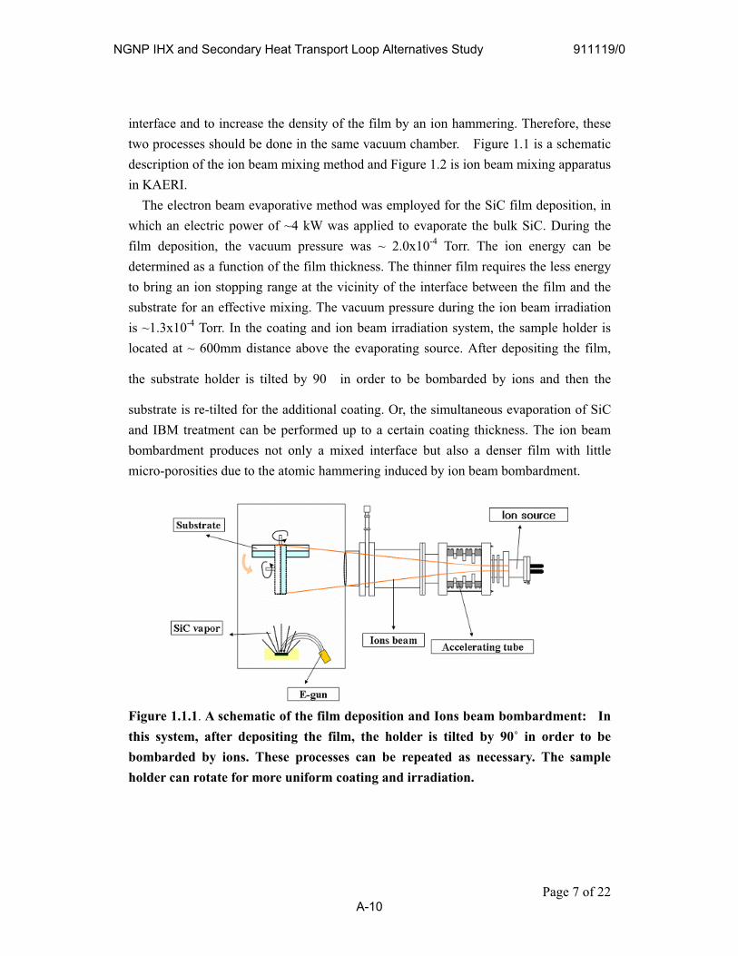
interface and to increase the density of the film by an ion hammering. Therefore, these two processes should be done in the same vacuum chamber. Figure 1.1 is a schematic description of the ion beam mixing method and Figure 1.2 is ion beam mixing apparatus in KAERI.
The electron beam evaporative method was employed for the SiC film deposition, in which an electric power of ~4 kW was applied to evaporate the bulk SiC. During the film deposition, the vacuum pressure was ~ 2.0x10⁻⁴ Torr. The ion energy can be determined as a function of the film thickness. The thinner film requires the less energy to bring an ion stopping range at the vicinity of the interface between the film and the substrate for an effective mixing. The vacuum pressure during the ion beam irradiation is ~1.3x10⁻⁴ Torr. In the coating and ion beam irradiation system, the sample holder is located at ~ 600mm distance above the evaporating source. After depositing the film,
the substrate holder is tilted by 90 in order to be bombarded by ions and then the
substrate is re-tilted for the additional coating. Or, the simultaneous evaporation of SiC and IBM treatment can be performed up to a certain coating thickness. The ion beam bombardment produces not only a mixed interface but also a denser film with little micro-porosities due to the atomic hammering induced by ion beam bombardment.
Figure 1.1.1. A schematic of the film deposition and Ions beam bombardment: In this system, after depositing the film, the holder is tilted by 90˚ in order to be bombarded by ions. These processes can be repeated as necessary. The sample holder can rotate for more uniform coating and irradiation.
Page 7 of 22
NGNP IHX and Secondary Heat Transport Loop Alternatives Study 911119/0
A-10
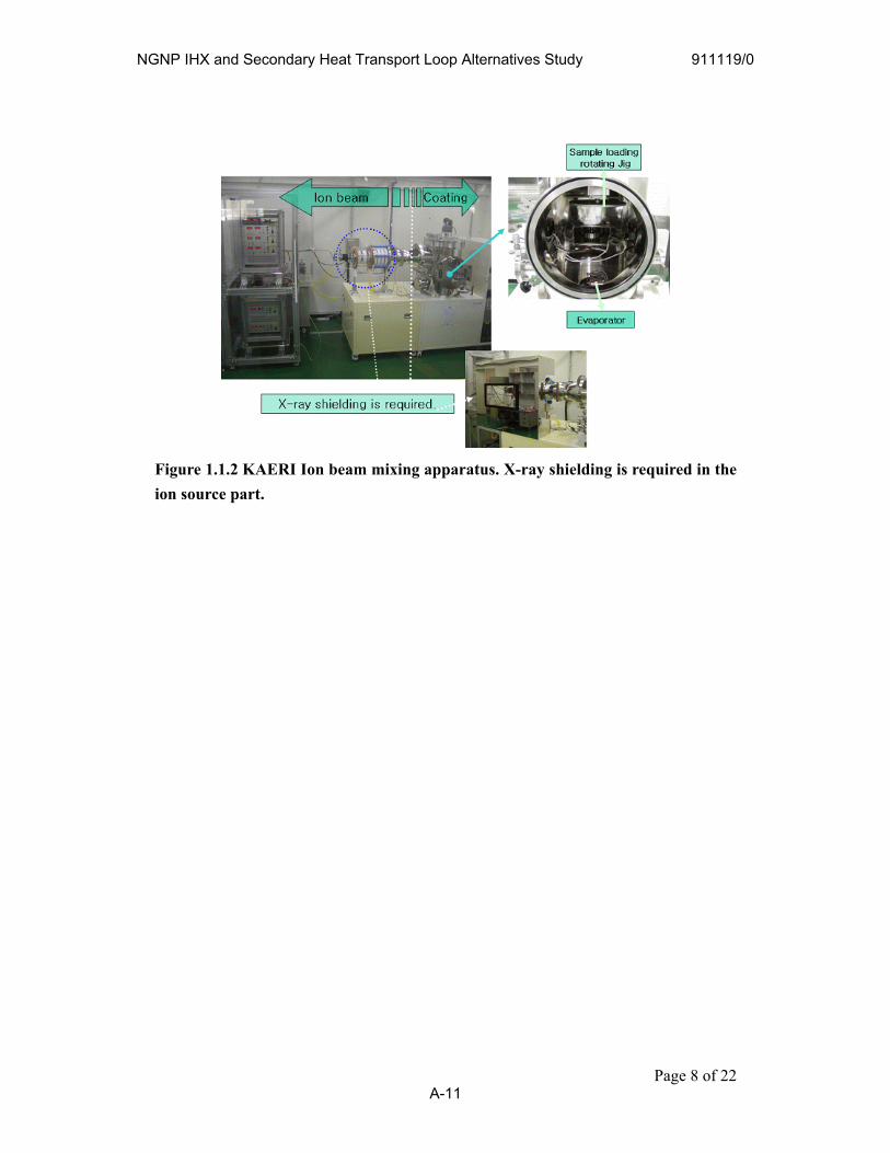
Figure 1.1.2 KAERI Ion beam mixing apparatus. X-ray shielding is required in the ion source part.
Page 8 of 22
NGNP IHX and Secondary Heat Transport Loop Alternatives Study 911119/0
A-11
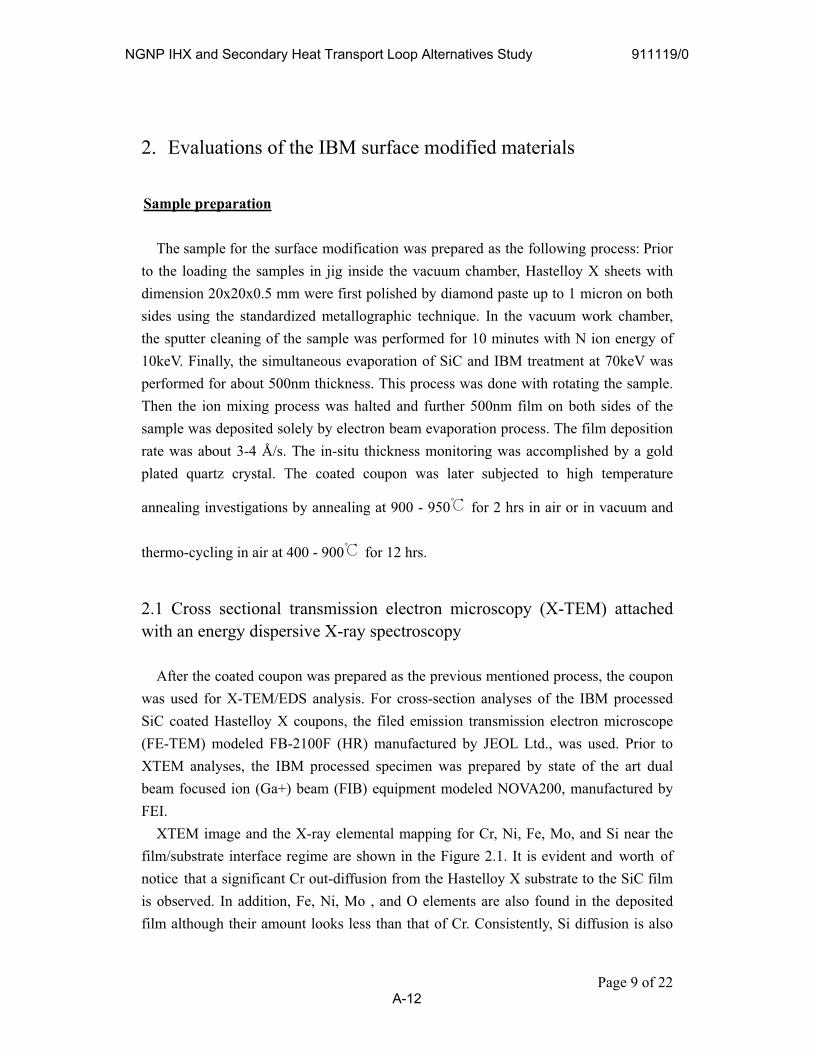
2. Evaluations of the IBM surface modified materials
Sample preparation
The sample for the surface modification was prepared as the following process: Prior to the loading the samples in jig inside the vacuum chamber, Hastelloy X sheets with dimension 20x20x0.5 mm were first polished by diamond paste up to 1 micron on both sides using the standardized metallographic technique. In the vacuum work chamber, the sputter cleaning of the sample was performed for 10 minutes with N ion energy of 10keV. Finally, the simultaneous evaporation of SiC and IBM treatment at 70keV was performed for about 500nm thickness. This process was done with rotating the sample. Then the ion mixing process was halted and further 500nm film on both sides of the sample was deposited solely by electron beam evaporation process. The film deposition rate was about 3-4 Å/s. The in-situ thickness monitoring was accomplished by a gold plated quartz crystal. The coated coupon was later subjected to high temperature
annealing investigations by annealing at 900 - 950 for 2 hrs in air or in vacuum and
thermo-cycling in air at 400 - 900 for 12 hrs.
2.1 Cross sectional transmission electron microscopy (X-TEM) attached with an energy dispersive X-ray spectroscopy
After the coated coupon was prepared as the previous mentioned process, the coupon was used for X-TEM/EDS analysis. For cross-section analyses of the IBM processed SiC coated Hastelloy X coupons, the filed emission transmission electron microscope (FE-TEM) modeled FB-2100F (HR) manufactured by JEOL Ltd., was used. Prior to XTEM analyses, the IBM processed specimen was prepared by state of the art dual beam focused ion (Ga+) beam (FIB) equipment modeled NOVA200, manufactured by FEI.
XTEM image and the X-ray elemental mapping for Cr, Ni, Fe, Mo, and Si near the film/substrate interface regime are shown in the Figure 2.1. It is evident and worth of notice that a significant Cr out-diffusion from the Hastelloy X substrate to the SiC film is observed. In addition, Fe, Ni, Mo , and O elements are also found in the deposited film although their amount looks less than that of Cr. Consistently, Si diffusion is also
Page 9 of 22
NGNP IHX and Secondary Heat Transport Loop Alternatives Study 911119/0
A-12

observed as shown in Figure 2.1.
Figure 2.1. X-TEM image and EDS elemental mapping at the film/substrate interface.
des oxides which is in good agreement It is expected that high temperature annealing has resulted in the formation of
submicron Ni-based silicates and Cr-based carbi
Page 10 of 22
NGNP IHX and Secondary Heat Transport Loop Alternatives Study 911119/0
A-13
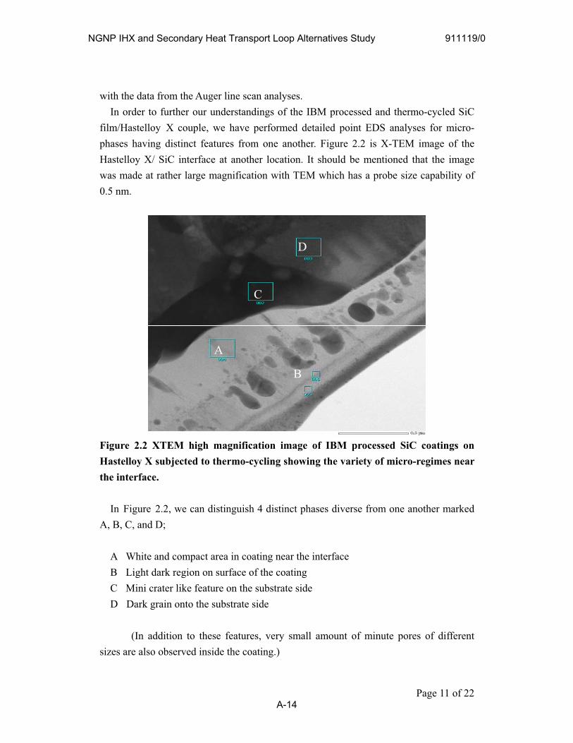
of 22
wi
e at rather large magnification with TEM which has a probe size capability of 0.5 nm.
bjected to thermo-cycling showing the variety of micro-regimes near the interface.
we can distinguish 4 distinct phases diverse from one another marked A, B, C, and D;
interface
trate side k grain onto the substrate side
small amount of minute pores of different siz
th the data from the Auger line scan analyses. In order to further our understandings of the IBM processed and thermo-cycled SiC
film/Hastelloy X couple, we have performed detailed point EDS analyses for micro-phases having distinct features from one another. Figure 2.2 is X-TEM image of the Hastelloy X/ SiC interface at another location. It should be mentioned that the image was mad
Figure 2.2 XTEM high magnification image of IBM processed SiC coatings on Hastelloy X su
A
D
B
C
In Figure 2.2,
A White and compact area in coating near the B Light dark region on surface of the coating C Mini crater like feature on the subsD Dar
(In addition to these features, very es are also observed inside the coating.)
Page 11
NGNP IHX and Secondary Heat Transport Loop Alternatives Study 911119/0
A-14

Point EDS /EMPA analyses revealed that the region A is rich in O, Cr, and Si contents. The region B is dominated in O, Si, and Cr contents. The region B also shows the
presence o
f carbon (4 atomic %) which is slightly larger than that was observed in the re
hermal annealing thereby contributing to eutectic phase formations inside th
ed SiC coatings may result from to an inter-diffusion species across the in
theaction should be helpful for the film adhesion and for the corrosion protectiveness
n microscopy (X-SEM) and energy ispersive X-ray spectroscopy (EDS)
terface (Figure 2.3b), implying that th
gest that the mixture does not exhibit any adverse effect in the service performance.
gion A. The regions C and D represent another kind of distinct features in the TEM
micrograph onto the substrate side. The microanalyses revealed them to be inhabited by the micro-constituents of Hastelloy X, however, the region C was found to be affected more due to t
e coating. The formation of ternary micro-phase traces found inside the IBM processed and
thermo-cyclterface.Summarily, unless the SiC film is peeled-off by a thermal strain, a reaction between
SiC and Hastelloy X at the interface seems feasible at a high temperature, and re
2.2 Cross sectional scanning electrod
Cross-sectional back scattered electron images of an as-deposited SiC/ Hastelloy X sample (Figure 2.3a) and an IBM SiC /Hastelloy X after heating (Figure 2.3b) were observed. The cross section of the 1 m SiC film deposited on Hastelloy X sample shows a clear interface between the film and the substrate (Figure 2.3a). However, the IBM treated and annealed sample shows a blurred in
e interfacial reaction occurred during the heating. Table 2.1 shows the EDS analytical results of S1 (In the substrate near the interface)
and S2 (in the film) points in Figure 2.3a. As shown in Table 2.1, it seems SiC and SiO2
co-exist in the film, which implies that oxides exist inherently in the target SiC material. In fact, our earlier analysis of the bulk SiC used as an evaporation source showed that the near surface oxygen concentration in the bulk SiC was about 12 - 25% depending on the analysis area as determined with X-ray photoelectron spectroscopy. Si detected at S1 and Cr, Fe, and Ni at S2 should be due to sampling volume of EDX. Too much C existence in the film may be due to carbonaceous contaminants on the cross sectional surface. Our investigation on the thermal and corrosion behaviors of the SiC film mixed with SiO2 sug
Page 12 of 22
NGNP IHX and Secondary Heat Transport Loop Alternatives Study 911119/0
A-15
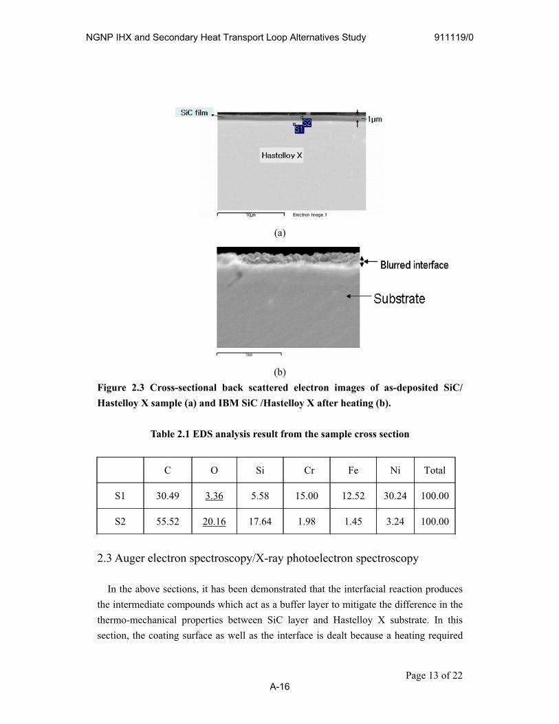
(a)
(b)Figure 2.3 Cross-sectional back scattered electron images of as-deposited SiC/ Hastelloy X sample (a) and IBM SiC /Hastelloy X after heating (b).
Table 2.1 EDS analysis result from the sample cross section
C O Si Cr Fe Ni Total
S1 30.49 3.36 5.58 15.00 12.52 30.24 100.00
S2 55.52 20.16 17.64 1.98 1.45 3.24 100.00
2.3 Auger electron spectroscopy/X-ray photoelectron spectroscopy
In the above sections, it has been demonstrated that the interfacial reaction produces the intermediate compounds which act as a buffer layer to mitigate the difference in the thermo-mechanical properties between SiC layer and Hastelloy X substrate. In this section, the coating surface as well as the interface is dealt because a heating required
Page 13 of 22
NGNP IHX and Secondary Heat Transport Loop Alternatives Study 911119/0
A-16
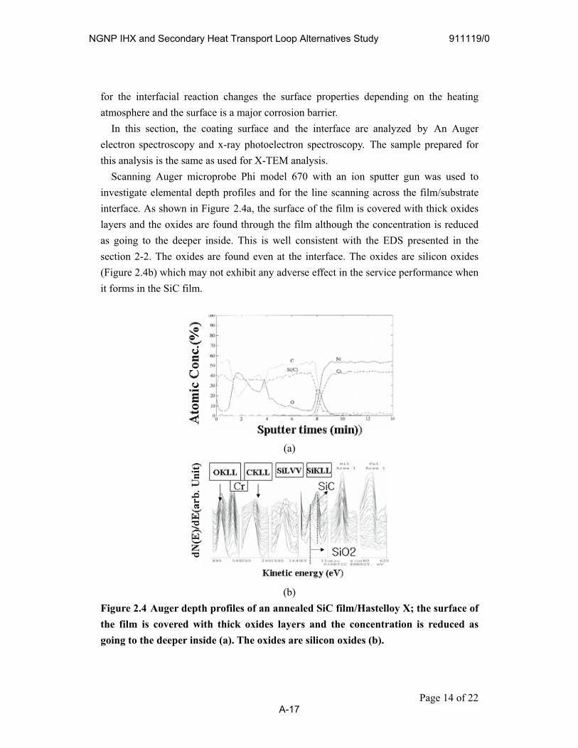
for the interfacial reaction changes the surface properties depending on the heating atm
oscopy. The sample prepared for th
ot exhibit any adverse effect in the service performance when forms in the SiC film.
osphere and the surface is a major corrosion barrier. In this section, the coating surface and the interface are analyzed by An Auger
electron spectroscopy and x-ray photoelectron spectris analysis is the same as used for X-TEM analysis. Scanning Auger microprobe Phi model 670 with an ion sputter gun was used to
investigate elemental depth profiles and for the line scanning across the film/substrate interface. As shown in Figure 2.4a, the surface of the film is covered with thick oxides layers and the oxides are found through the film although the concentration is reduced as going to the deeper inside. This is well consistent with the EDS presented in the section 2-2. The oxides are found even at the interface. The oxides are silicon oxides (Figure 2.4b) which may nit
(a)
(b)Figure 2.4 Auger depth profiles of an annealed SiC film/Hastelloy X; the surface of the film is covered with thick oxides layers and the concentration is reduced as going to the deeper inside (a). The oxides are silicon oxides (b).
Page 14 of 22
NGNP IHX and Secondary Heat Transport Loop Alternatives Study 911119/0
A-17
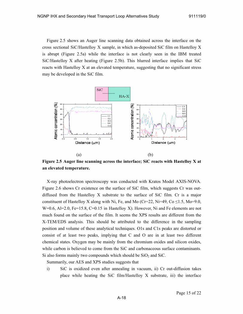
Figure 2.5 shows an Auger line scanning data obtained across the interface on the cross sectional SiC/Hastelloy X sample, in which as-deposited SiC film on Hastelloy X is abrupt (Figure 2.5a) while the interface is not clearly seen in the IBM treated SiC/Hastelloy X after heating (Figure 2.5b). This blurred interface implies that SiC reacts with Hastelloy X at an elevated temperature, suggesting that no significant stress m loped in the SiC film. ay be deve
(a) (b) Figure 2.5 Auger line scanning across the interface; SiC reacts with Hastelloy X at an elevated temperature.
ace contaminants. Si iO2 and SiC.
X-ray photoelectron spectroscopy was conducted with Kratos Model AXIS-NOVA. Figure 2.6 shows Cr existence on the surface of SiC film, which suggests Cr was out-diffused from the Hastelloy X substrate to the surface of SiC film. Cr is a major constituent of Hastelloy X along with Ni, Fe, and Mo (Cr=22, Ni=49, Co 1.5, Mo=9.0, W=0.6, Al=2.0, Fe=15.8, C=0.15 in Hastelloy X). However, Ni and Fe elements are not much found on the surface of the film. It seems the XPS results are different from the X-TEM/EDS analysis. This should be attributed to the difference in the sampling position and volume of these analytical techniques. O1s and C1s peaks are distorted or consist of at least two peaks, implying that C and O are in at least two different chemical states. Oxygen may be mainly from the chromium oxides and silicon oxides, while carbon is believed to come from the SiC and carbonaceous surf
also forms mainly two compounds which should be SSummarily, our AES and XPS studies suggests that i) SiC is oxidized even after annealing in vacuum, ii) Cr out-diffusion takes
place while heating the SiC film/Hastelloy X substrate, iii) the interface
Page 15 of 22
NGNP IHX and Secondary Heat Transport Loop Alternatives Study 911119/0
A-18
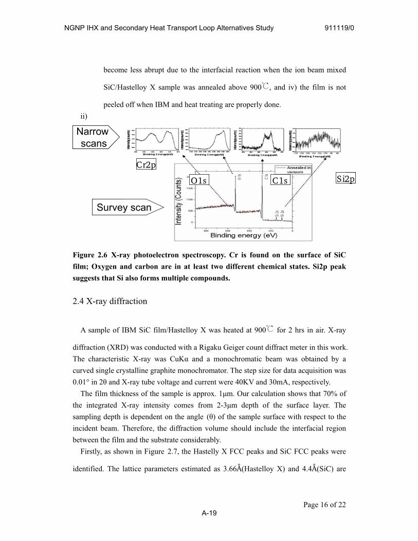
become less abrupt due to the interfacial reaction when the ion beam mixed
SiC/Hastelloy X sample was annealed above 900 , and iv) the film is not
eeled off when IBM and heat treating are properly done. ii)
p
Survey scan
Narrow scans
Survey scan
Narrow scans
Figure 2.6 X-ray photoelectron spectroscopy. Cr is found on the surface of SiC film; Oxygen and carbon are in at least two different chemical states. Si2p peak
ggests that Si also forms multiple compounds.
.4 X-ray diffraction
was 0.
e should include the interfacial region be
su
2
A sample of IBM SiC film/Hastelloy X was heated at 900 for 2 hrs in air. X-ray
diffraction (XRD) was conducted with a Rigaku Geiger count diffract meter in this work. The characteristic X-ray was CuK and a monochromatic beam was obtained by a curved single crystalline graphite monochromator. The step size for data acquisition
01° in 2 and X-ray tube voltage and current were 40KV and 30mA, respectively. The film thickness of the sample is approx. 1 m. Our calculation shows that 70% of
the integrated X-ray intensity comes from 2-3 m depth of the surface layer. The sampling depth is dependent on the angle ( ) of the sample surface with respect to the incident beam. Therefore, the diffraction volum
tween the film and the substrate considerably. Firstly, as shown in Figure 2.7, the Hastelly X FCC peaks and SiC FCC peaks were
identified. The lattice parameters estimated as 3.66 (Hastelloy X) and 4.4 (SiC) are
Page 16 of 22
NGNP IHX and Secondary Heat Transport Loop Alternatives Study 911119/0
A-19
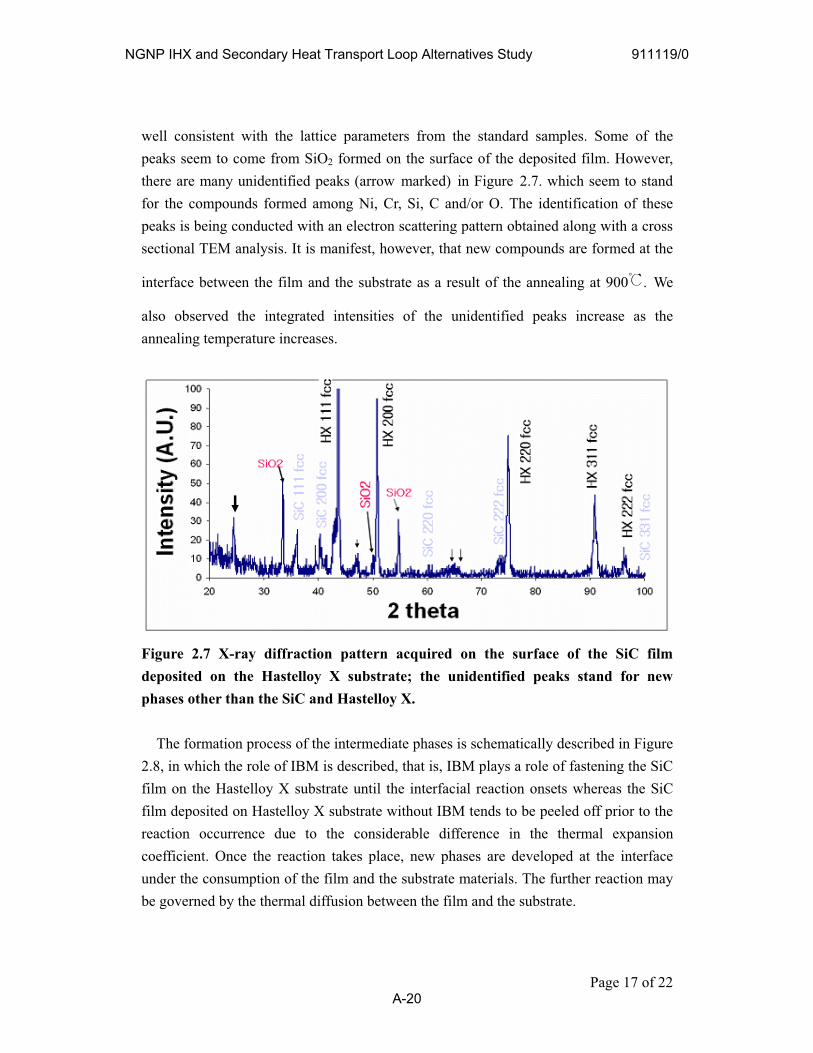
Page 17 of 22
tensities of the unidentified peaks increase as the annealing temperature increases.
well consistent with the lattice parameters from the standard samples. Some of the peaks seem to come from SiO2 formed on the surface of the deposited film. However, there are many unidentified peaks (arrow marked) in Figure 2.7. which seem to stand for the compounds formed among Ni, Cr, Si, C and/or O. The identification of these peaks is being conducted with an electron scattering pattern obtained along with a cross sectional TEM analysis. It is manifest, however, that new compounds are formed at the
interface between the film and the substrate as a result of the annealing at 900 . We
also observed the integrated in
Figure 2.7 X-ray diffraction pattern acquired on the surface of the SiC film deposited on the Hastelloy X substrate; the unidentified peaks stand for new
hases other than the SiC and Hastelloy X.
r reaction may be governed by the thermal diffusion between the film and the substrate.
p
The formation process of the intermediate phases is schematically described in Figure 2.8, in which the role of IBM is described, that is, IBM plays a role of fastening the SiC film on the Hastelloy X substrate until the interfacial reaction onsets whereas the SiC film deposited on Hastelloy X substrate without IBM tends to be peeled off prior to the reaction occurrence due to the considerable difference in the thermal expansion coefficient. Once the reaction takes place, new phases are developed at the interface under the consumption of the film and the substrate materials. The furthe
NGNP IHX and Secondary Heat Transport Loop Alternatives Study 911119/0
A-20

Figure 2.8 A schematic description of the process of new intermediate phases formation: IBM fastens the SiC film on the Hastelloy X substrate until the interfacial reaction onsets, whereas the SiC film deposited on Hastelloy X substrate without IBM tends to be peeled off prior to the reaction occurrence.
2.5 Corrosion test in sulfuric acid
A preliminary study on the corrosion behavior was performed in an aqueous sulfuric acid (90%, +10% water). The bare Hastelloy X sample was 20mmx20mmx0.5mm. The
sample prepared in this study was 2 μm thick IBM SiC film with annealing at 950 for
4 hrs. It was compared with a bare Hastelloy X. Figure 2.9 shows comparison of the rates of corrosion of the uncoated Hastelloy X coupon and coating/IBM processed
coupons which were separately prepared for boiling H2SO4 corrosion test at 300 .
The coated sample exhibits almost no weight change up to 10 hrs and then a small weight reduction was observed after 16 hrs. The weight reduction is believed to be due to some imperfection in the coating layer. The bare sample exhibits a huge weight reduction at the beginning, followed by a stable and small weight reduction as increasing the corrosion time. This may be due to a formation of the passive layer that should be oxides.
The corrosion resistance of Hastelloy X coupons comes from the presence of chemically stable SiC films that are ion-beam-hammered for densification within the film and better adhesion at the interface. In IBM, it is suggestive that the process should
Page 18 of 22
NGNP IHX and Secondary Heat Transport Loop Alternatives Study 911119/0
A-21

be optimized for the development for the well adhered film with little micro-porosity.
2 4 6 8 10 12 14 16 18 200
20
Wei
ght L
oss
Rat
e(M
g/cm
2 )
T im e (H rs)
IBM 2 m film /Air AnnealBare Hastelloy X
Figure 2.9 A comparison of the corrosion rate between the IBM coated SiC film
annealed at 950 and a bare sample.
Page 19 of 22
NGNP IHX and Secondary Heat Transport Loop Alternatives Study 911119/0
A-22

3. Potential uses for NGNP components including PHE It has been studied so far that the IBM surface modification improves the corrosion
property of metallic materials. Therefore, IBM can be mainly used for the components operating at a severe corrosive environment. Process heat exchanger is a key component which transfers the heat of the intermediate loop to the hydrogen production loop. This heat exchanger will suffer the extreme environments of high corrosion, high temperature and high differential pressure. A metallic heat exchanger has a short lifetime due to the complex interaction between stress and corrosion. A ceramic heat exchanger with a strong corrosion resistance has difficulties in the manufacturing and the thermal shock resistance because of its low fracture toughness. KAERI has implemented the IBM surface modification technology to solve this technical problem. Based upon aforementioned design requirements, a hybrid heat exchanger shown in Figure 3.1 is designed. The heat exchanger exposed to helium gas is designed of a plate type heat exchanger where flow channel is small enough to withstand the mechanical loading.
Figure 3.1 Process Heat Exchanger with IBM Technology However, the flow channel of the sulfuric gas channel is designed of a plate-fin type
heat exchanger in order to provide the space of the catalyst. Also, the plate-fin type heat exchanger provides sufficient space for the catalyst maintenance. Comparing to a plate-fin type heat exchanger, this hybrid heat exchanger is more efficient to withstand the
Page 20 of 22
NGNP IHX and Secondary Heat Transport Loop Alternatives Study 911119/0
A-23
pressure difference between loops. Layout of the heat exchanger is a counter flow type since the decomposition of sulfuric oxides gas is an endothermic reaction. In order to enhance corrosion resistance, coating and ion beam mixing technology is applied to the process heat exchanger. The surface modification consists of coating and ion beam mixing. Silicon carbide was chosen as the coating material of process heat exchanger. It has been demonstrated that the silicon carbide can withstand the aggressive environments from the 400days corrosion test in KAERI. The high resistance of SiC to the corrosion could be due to the very strong covalent bonding between silicon and carbon and its tetrahedral coordination. Hastelloy X has been selected as a metallic substrate because it has high mechanical strength at the elevated temperature. Also, the thermal expansion coefficient of Hastelloy X is more similar to that of SiC than any other Ni-based alloys and its corrosion resistance in the SO3/SO2 gases has been known to be better than the other Ni based alloys.
Except for PHE, IBM can be applied to the components working at the corrosive environment. Many heat exchangers, vessels, pipe and valves are used in the S-I process of the hydrogen production system and they are exposed to corrosive fluids such as sulfuric acid and/or HI. All of theses components are potential candidates of the IBM surface modification technology. The protections of the sensors and metallic connections of the ceramic pipes from corrosive environment are another practical application of the IBM technology. Since surface modification by the IBM improves not only the corrosion resistance but also the wear and the oxidation resistance. Although quantitative evaluation was not done, the application of IBM to intermediate heat exchanger may improve lifetime of the plate type intermediate heat exchanger due to improvement of corrosion, wear, and oxidation resistance. The change of tritium permeability due to coating and ion beam mixing is a research items to be investigated quantitatively for further application to intermediate heat exchanger. It can be used for the impeller of the circulator and the turbine blade to improve the wear resistance by using the wear resistant coating materials.
There are some limitations in the practical application of ion beam mixing surface modification technology. It can not be applied to the huge structure due to the size of the IBM chamber size. It is also difficult to apply IBM technology for the narrow concave shaped structure. As for the tube shaped structure, it is difficult to apply IBM to the inner surface of the tube but there is no problem for the outer surface.
Page 21 of 22
NGNP IHX and Secondary Heat Transport Loop Alternatives Study 911119/0
A-24
Page 22 of 22
REFERENCES
[Bolse, 1998] W. Bolse, Mat. Sci. Eng. A, 253, 194 (1998).
[Fujikawa, 2004] S. Fujikawa, H. Hatashi, T. Nakazawa, K. Kawasaki, T. Iyoku, S. Nakagawa and N. Sakaba., J. Nucl. Sci. Technol., 41, 1245 (2004).
[Nakatani, 2005] R. Nakatani, R. Taniguchi, Y. Chimi, N. Ishikawa, M. Fukuzumi, Y. Kato, H. Tsuchida, N. Matsunami, A. Iwase, Nucl. Inst. Meth. B 230, 234 (2005).
[Nastasi, 1994] M. Nastasi and J. W. Mayer, Materials Science and Engineering, R12, No. 1, (1994).
[Park, 2007] J.W. Park and J. Chang, Journal of Nuclear Materials, Vol.362, (2007)
[Ota, 2005] H. Ota, S. Kubo, M. Hodotsuka, T. Inatomi, M. Kobayashi, A. Terada, S. Kasahara, R. Hino, K. Ogura, S. Maruyama, Proceedings of the 13th International Conference on Nuclear Engineering, 332, ICONE-13-50494, Beijing, China, May 16–20 (2005).
[Riviere, 1998] J.-P. Riviere, J. Delafond, P. Misaelides, F. Noli, Surf. Coat. Technol. 100-101, 243 (1998).
[Uchida, 2004] H. Uchida, M. Yamashita, S. Hanaki, T. Ueta, Mat. Sci. Eng. A 387, 758 (2004).
[Zhang, 2006] K. Zhang, K. P. Lieb, V. Milinovic, M. Uhrmacher, S. Klaumuenzer, Nucl. Inst. Meth. B. , 249, 167 (2006).
NGNP IHX and Secondary Heat Transport Loop Alternatives Study 911119/0
A-25

P.O. BOX 85608 SAN DIEGO, CA 92186-5608 (858) 455-3000