areva np inc., - inl advanced reactor technologies documents/areva/ngnp... · document no.:...
TRANSCRIPT

20004-015 (09/30/2008)
Page 1 of 55
AREVA NP Inc.,an AREVA and Siemens company
Engineering Information Record
Document No: 51 - 9105936 - 001
NGNP Nuclear Heat Source System Boundaries and Interfaces
BEA Contract No. 00075310
Disclaimer
This report was prepared as an account of work sponsored by an agency of the United States Government. Neither the United States Government nor any agency thereof, nor any of their employees, nor their contractors and subcontractors, makes any warranty, express or implied, or assumes any legal liability or responsibility for the accuracy, completeness, or usefulness of any information, apparatus, product, or process disclosed, or represents that its use would not infringe privately owned rights. Reference herein to any specific commercial product, process, or service by trade name, trademark, manufacturer, or otherwise does not necessarily constitute or imply its endorsement, recommendation, or favoring by the United States Government or any agency thereof. The views and opinions of authors expressed herein do not necessarily state or reflect those of the United States Government or any agency thereof.


20004-015 (09/30/2008)
Document No.: 51-9105936-001 AREVA NP Inc., an AREVA and Siemens company
NGNP Nuclear Heat Source System Boundaries and Interfaces
Page 3
Record of Revision
Revision No. Date
Pages/Sections/ Paragraphs
Changed Brief Description / Change Authorization 000 3-19-09 ALL Initial Release
001 Section 1.0 Placed acronyms in alphabetical order Section 2.0 3rd paragraph, 4th sentence “… at their physical …” was “… at its
physical”. Added a 4th paragraph. Section 3.0 Added “(Reference 1) to the 1st sentence. Figure 8.1-2 Updated the Figure to include RS component callouts Figure 8.2-1 Updated the Figure to only list components of the vessel system. Table 8.2-1 Other interfaces column, added radiological interface # 2. Included
components column, “Cross vessel” was “Cross over vessel”. Boundaries column, added boundary # 14.
Section 8.3 Added reference to Figure 8.3-1 in the 2nd sentence Section 8.5 In the 1st sentence of the 3rd paragraph, “un-insulated portions of the
RPV” was “un-insulated RPV”. Inserted 3rd sentence into the 3rd paragraph.
Figure 8.5-1 Added “Dedicated cooling system” Figure 8.6-1 Changed title from “FUEL HANDLING MACHINE GRAPPLE” to
“FUEL HANDLING MACHINE GRAPPLING FEATURE” Section 8.8 “see Figure 8.6-2” was “see 8.6-3” Section 8.9 1st sentence “ … and maintains the correct coolant chemistry.” was
“and maintains the required atmosphere.” Section 8.10 Revised first sentence. Inserted the second sentence. Table 8.10-1 Added a general boundary in the Boundaries column Section 8.11 Reworded 1st paragraph and inserted new 4th paragraph Figure 8-19-1 “Water/Steam” was “Steam – Water” Table 8.19-1 In 2 places, “Power Conversion System at the pipe connections of the
first dump valves.” was “Power Conversion System at the pipe connection of the first dump valve.”
All Minor grammatical corrections as deemed necessary All Tables as
noted All Tables that have no Included components listed, changed “None” to “TBD”

Document No.: 51-9105936-001 AREVA NP Inc., an AREVA and Siemens company
NGNP Nuclear Heat Source System Boundaries and Interfaces
Page 4
Table of Contents Page
REVISION 001 SIGNATURE BLOCK.......................................................................................................2
RECORD OF REVISION ..........................................................................................................................3
LIST OF TABLES .....................................................................................................................................6
LIST OF FIGURES ...................................................................................................................................7
1.0 LIST OF ACRONYMS...................................................................................................................8
2.0 INTRODUCTION...........................................................................................................................9
3.0 SCOPE..........................................................................................................................................9
4.0 PURPOSE.....................................................................................................................................9
5.0 APPROACH................................................................................................................................10
6.0 ASSUMPTIONS..........................................................................................................................10
7.0 DESIGN INPUTS ........................................................................................................................10
8.0 NUCLEAR HEAT SOURCE DESCRIPTION ..............................................................................10 8.1 Reactor system ...............................................................................................................10 8.2 Vessel system .................................................................................................................16 8.3 Main Heat Transport System...........................................................................................20 8.4 Shutdown Cooling System ..............................................................................................24 8.5 Reactor Cavity Cooling System.......................................................................................26 8.6 Fuel Handling System .....................................................................................................28 8.7 Spent Fuel Storage and Cooling System ........................................................................31 8.8 New fuel handling and storage system ...........................................................................33 8.9 Helium service system ....................................................................................................34 8.10 NI HVAC system .............................................................................................................35 8.11 Plant Electrical System....................................................................................................36 8.12 NI Cooling Water System................................................................................................38 8.13 Component Handling System..........................................................................................40 8.14 Reactor Protection System..............................................................................................42 8.15 NHS Investment Protection System ................................................................................43 8.16 NHS Control and Monitoring System ..............................................................................45

Document No.: 51-9105936-001 AREVA NP Inc., an AREVA and Siemens company
NGNP Nuclear Heat Source System Boundaries and Interfaces
Table of Contents
(continued)
Page
Page 5
8.17 Control Room and Operator Interface System ................................................................46 8.18 Radioactive Waste and Decontamination System ..........................................................46 8.19 STEAM/WATER DUMP SYSTEM...................................................................................47
9.0 REFERENCES............................................................................................................................49
APPENDIX A : NHS SYSTEM BOUNDARY MATRIX ......................................................................................... A-1
APPENDIX B : NHS SYSTEM PHYSICAL INTERFACE MATRIX ...................................................................... B-1
APPENDIX C : NHS SYSTEM ELECTRICAL INTERFACE MATRIX..................................................................C-1
APPENDIX D : NHS SYSTEM RADIOLOGICAL CONCERNS MATRIX.............................................................D-1
APPENDIX E : NHS SYSTEM THERMAL HYDRAULIC INTERFACE MATRIX ................................................. E-1
APPENDIX F : NHS SYSTEM HEAT TRANSFER INTERFACE MATRIX .......................................................... F-1
Document No.: 51-9105936-001 AREVA NP Inc., an AREVA and Siemens company
NGNP Nuclear Heat Source System Boundaries and Interfaces
Page 6
List of Tables
Page
TABLE 8.1-1 REACTOR SYSTEM BOUNDARIES AND INTERFACES...............................................14 TABLE 8.2-1 VESSEL SYSTEM BOUNDARIES AND INTERFACES ...................................................18 TABLE 8.3-1 MAIN HEAT TRANSPORT SYSTEM BOUNDARIES AND INTERFACES......................22 TABLE 8.4-1 SHUTDOWN COOLING SYSTEM BOUNDARIES AND INTERFACES..........................25 TABLE 8.5-1 RCCS BOUNDARIES AND INTERFACES.......................................................................27 TABLE 8.6-1 FUEL HANDLING SYSTEM BOUNDARIES AND INTERFACES....................................30 TABLE 8.7-1 SPENT FUEL STORAGE AND COOLING SYSTEM BOUNDARIES AND INTERFACES32 TABLE 8.8-1 NEW FUEL HANDLING AND STORAGE SYSTEM BOUNDARIES AND INTERFACES33 TABLE 8.9-1 HELIUM SERVICE SYSTEM BOUNDARIES AND INTERFACES ..................................34 TABLE 8.10-1 NI HVAC SYSTEM BOUNDARIES AND INTERFACES................................................35 TABLE 8.11-1 PLANT ELECTRICAL SYSTEM BOUNDARIES AND INTERFACES............................37 TABLE 8.12-1 NI COOLING WATER SYSTEM BOUNDARIES AND INTERFACES ...........................39 TABLE 8.13-1 COMPONENT HANDLING SYSTEM BOUNDARIES AND INTERFACES ...................41 TABLE 8.14-1 REACTOR PROTECTION SYSTEM BOUNDARIES AND INTERFACES ....................42 TABLE 8.15-1 NHS INVESTMENT PROTECTION SYSTEM BOUNDARIES AND INTERFACES ......44 TABLE 8.16-1 NCMS BOUNDARIES AND INTERFACES....................................................................45 TABLE 8.17-1 CROIS BOUNDARIES AND INTERFACES...................................................................46 TABLE 8.18-1 RWDS BOUNDARIES AND INTERFACES ...................................................................47 TABLE 8.19-1 STEAM/WATER DUMP SYSTEM BOUNDARIES AND INTERFACES ........................48

Document No.: 51-9105936-001 AREVA NP Inc., an AREVA and Siemens company
NGNP Nuclear Heat Source System Boundaries and Interfaces
Page 7
List of Figures
Page
FIGURE 8.1-1 CORE PLAN VIEW .........................................................................................................11 FIGURE 8.1-2 REACTOR SECTION VIEW ...........................................................................................12 FIGURE 8.1-3 GRAPHITE BLOCK (ACTIVE ELEMENT) ......................................................................13 FIGURE 8.2-1 VESSEL SYSTEM COMPONENTS................................................................................17 FIGURE 8.3-1 MAIN HEAT TRANSPORT SYSTEM FLOW PATH........................................................21 FIGURE 8.4-1 SHUTDOWN COOLING SYSTEM..................................................................................24 FIGURE 8.5-1 REACTOR CAVITY COOLING SYSTEM SCHEMATIC .................................................26 FIGURE 8.6-1 FUEL HANDLING MACHINE GRAPPLING FEATURE ..................................................28 FIGURE 8.6-2 FUEL HANDLING SYSTEM PLAN VIEW.......................................................................29 FIGURE 8.19-1 STEAM/WATER DUMP SYSTEM ...............................................................................48

Document No.: 51-9105936-001 AREVA NP Inc., an AREVA and Siemens company
NGNP Nuclear Heat Source System Boundaries and Interfaces
Page 8
1.0 LIST OF ACRONYMS
Acronym Description CHS Component Handling System CROIS NHS Control Room Operator Interface System DCC Depressurized conduction cooldown EACS Essential AC electrical system EDCS Essential DC electrical system FHS Fuel Handling System HSS Helium Service System HTR High Temperature Reactor IPS Nuclear Heat Source Investment Protection System MHTS Main Heat Transport System NCA Neutron control assembly NCMS NHS Control & Monitoring System NFHS New Fuel Handling and Storage System NGNP Next Generation Nuclear Power NHS Nuclear Heat Source NI Nuclear island NICWS Nuclear Island Cooling Water System NIHVAC Nuclear Island Heating and Air Conditioning PACS Plant AC electrical system PCC Pressurized conduction cooldown PCS Power Conversion System PDCS Plant DC electrical system PES Plant Electrical System PUP Plant uninterruptible power supply RCCS Reactor Cavity Cooling System RPS Reactor Protection System RPV Reactor pressure vessel RS Reactor System RWDS Radioactive Waste and Decontamination System SCS Shutdown Cooling System SCW Site and Civil Works SCWS Shutdown Cooling Water Subsystem SFSS Spent Fuel Storage and Cooling System SG Steam generator VS Vessel System

Document No.: 51-9105936-001 AREVA NP Inc., an AREVA and Siemens company
NGNP Nuclear Heat Source System Boundaries and Interfaces
Page 9
2.0 INTRODUCTION NGNP Background: The Next Generation Nuclear Power plant (NGNP) is a modular gas cooled High Temperature Reactor (HTR) electrical power plant. The power plant can also be used to generate steam for industrial process heat, or a combination of both electricity and process heat. The key attributes of the modular HTR that distinguish it from other reactor types are its fuel, a refractory fuel consisting of coated particles which are embedded in graphite moderator, and its helium coolant. These attributes not only provide for a high temperature capability that is unique among established reactor concepts but also offers fuel cycle flexibility. Additionally, these characteristics associated with limitations on power level and power density makes possible the development of a modular concept with inherent safety characteristics simpler than those employed by current light water reactor technology.
Objective: The objective of this document is to define the boundaries and interfaces of the major systems which make up the Nuclear Heat Source (NHS). Description of each system will be provided as needed to describe the boundaries and interfaces.
Document structure: For each major system of the NHS a brief verbal description of the system will be provided. Figures will be provided following the verbal description where deemed useful. After the description and Figures where used, a Table will be provided that lists the boundaries and interfaces. The boundaries will be described where possible at their physical location. The name of the system with which the boundary exists will be listed and the corresponding acronym listed in the interfaces. See Section 5.0 for additional information.
Document limitation: Changes were made to the system definitions of the NGNP Plant Design Requirements Document, 51-9106032-000 after the initial release of this document. In general, this does not significantly alter the NHS system boundaries and interfaces described herein. However, some nomenclature will have to be updated to make both documents fully consistent. Elimination of project funding precluded resolution of the detailed nomenclature at this time. Nonetheless, the boundaries provided in this document provide a reasonable starting point for initial conceptual design work.
3.0 SCOPE
The scope of information provided within this document pertains to the current AREVA-NP reference baseline design (Reference 1) for the NGNP project NHS systems. The NHS is considered to be limited to the primary (aka main) loop heat transport system and the secondary loop up to the first isolation valve from the steam generator and the first dump valve of the Steam/Water Dump System. The scope of this document does not include a detailed description of each of the NHS systems required for the NHS. A brief overview of each system will be provided sufficient to describe the system. The figures provided describe a NGNP general case and may not depict the exact details of a still immature AREVA-NP NGNP reference design. The accuracy of the component depictions does not affect the purpose of this document. A table will be provided for each system listing the boundaries and interfaces.
4.0 PURPOSE
The purpose of this document is to define the boundaries between the NHS systems required for the operation of the NHS and identify interfaces between those NHS systems. Where applicable, the boundary or interface will be described by the component or physical location on which the boundary or interface resides.

Document No.: 51-9105936-001 AREVA NP Inc., an AREVA and Siemens company
NGNP Nuclear Heat Source System Boundaries and Interfaces
Page 10
5.0 APPROACH
The systems which make up the NHS are listed in Section 8.0. A brief description is provided for each system that is meant to be generic as possible to provide flexibility as the plant design is refined. Specific components of the system are listed where needed to describe the system or interfaces of the system. The physical boundaries of each system are listed with the system name with which they bound. Specific interface points between systems that effect analysis or design are provided. Interface points may coincide with or help define boundaries but are not limited to physical boundaries. Five different interface categories are considered: physical, heat transfer, electrical & control, thermal hydraulic, and radiological. Thermal hydraulic is used to describe all heat balance and fluid flow considerations.
Two systems that are not part of the NHS are listed as boundaries. Those are Site & Civil Works (building structure) and Power Conversion System (secondary coolant loop).
6.0 ASSUMPTIONS
No assumptions were made in preparation of this document.
7.0 DESIGN INPUTS
None.
8.0 NUCLEAR HEAT SOURCE DESCRIPTION
The nuclear heat source is comprised of a graphite moderated nuclear reactor and heat transport system encased in pressure retaining vessels forming the main coolant loop. The reactor heats helium which is circulated through a steam generator where the heat is transferred to a secondary loop. The reactor core and the steam generator are located in separate pressure vessels connected together by a cross vessel. The heat generated from the reactor is transferred to the secondary loop to form steam. This steam can be used to drive an electrical generator via a steam turbine, used as process heat, or both. For the purpose of this document, the secondary loop is only considered up to the isolation valve. All auxiliary systems required for the function of the nuclear heat source systems such as controls, NIHVAC, refueling, etc. are included.
8.1 REACTOR SYSTEM
The purpose of the Reactor System is to generate heat for the power plant. The reactor is a prismatic block configuration; see Figures 8.1-1 and 8.1-2. The reference design is a graphite moderated helium cooled reactor. It is comprised of stacks of hexagonally shaped graphite blocks, see Figure 8.1-3. The blocks containing fissile material form a cylinder as shown in Figure 8.1-1 and are surrounded by reflector blocks, which contain no fissile material along the ID, OD, top and bottom. The stack is contained radially within a metallic core barrel. The reactor core rests atop a graphite core support assembly supported in turn by a metallic core support assembly. The reactor is controlled by neutron control equipment (neutron control and flux detection assemblies) which is considered part of the Reactor System. The Reactor System is considered to include all items contained within the reactor vessel, excluding the SCS circulator, SCS heat exchanger, and hot duct, up to the connection to the hot duct. The Reactor System also includes the reactor supports and reactor control elements. The reactor control elements include the neutron detectors that are external to the reactor vessel. See Table 8.1-1 for boundaries and interfaces.

Document No.: 51-9105936-001 AREVA NP Inc., an AREVA and Siemens company
NGNP Nuclear Heat Source System Boundaries and Interfaces
Page 11
Figure 8.1-1 CORE PLAN VIEW

Document No.: 51-9105936-001 AREVA NP Inc., an AREVA and Siemens company
NGNP Nuclear Heat Source System Boundaries and Interfaces
Page 12
Figure 8.1-2 REACTOR SECTION VIEW

Document No.: 51-9105936-001 AREVA NP Inc., an AREVA and Siemens company
NGNP Nuclear Heat Source System Boundaries and Interfaces
Page 13
Figure 8.1-3 GRAPHITE BLOCK (ACTIVE ELEMENT)

D
ocum
ent N
o.:
51-9
1059
36-0
01
AR
EVA
NP
Inc.
, an
AR
EVA
and
Sie
men
s co
mpa
nyN
GN
P N
ucle
ar H
eat S
ourc
e S
yste
m B
ound
arie
s an
d In
terfa
ces
P
age
14
TAB
LE 8
.1-1
REA
CTO
R S
YSTE
M B
OU
ND
AR
IES
AN
D IN
TER
FAC
ES
Syst
em
Incl
uded
com
pone
nts
Bou
ndar
ies
Phys
ical
inte
rfac
es
Oth
er in
terf
aces
R
eact
or S
yste
m
1) V
esse
l Sys
tem
at t
he
seis
mic
rest
rain
t key
s and
at
supp
ort r
ing
at lo
wer
hea
d of
ves
sel
2) V
esse
l Sys
tem
at
pene
tratio
ns fo
r NC
A a
nd
flux
dete
ctor
s 3)
NH
S C
ontro
l and
M
onito
ring
Syst
em a
t all
NC
A c
onne
ctio
ns th
at
perm
it re
mov
al o
f the
NC
A
4) R
eact
or P
rote
ctio
n Sy
stem
at b
orat
ed g
raph
ite
pelle
t hop
per (
NC
A)
conn
ectio
ns
5) N
HS
Con
trol a
nd
Mon
itorin
g Sy
stem
at
neut
ron
flux
dete
ctor
co
nnec
tions
6)
Fue
l Han
dlin
g Sy
stem
at
fuel
& re
flect
or e
lem
ents
7)
Mai
n H
eat T
rans
port
Syst
em a
t hot
duc
t / c
ore
barr
el c
onne
ctio
n 8)
Shu
tdow
n C
oolin
g Sy
stem
at d
uct c
onne
ctio
n to
cor
e su
ppor
t 9)
NH
S In
vest
men
t Pr
otec
tion
Syst
em a
t NC
A
cont
rols
for r
od d
rop
at
shut
dow
n 10
) Site
& C
ivil
Wor
ks a
t
1) S
eism
ic re
stra
int o
n th
e co
re b
arre
l with
ve
ssel
(VS)
2)
Con
tact
poi
nt b
etw
een
vess
el a
nd c
ore
supp
ort
stru
ctur
e (V
S)
3) H
ot d
uct c
onne
ctio
n at
cor
e ba
rrel
(MH
TS)
4) S
hutd
own
Coo
ling
Syst
em d
uct c
onne
ctio
n to
cor
e su
ppor
t (SC
S)
5) H
andl
ing
feat
ure
(gra
pplin
g ho
le) o
f the
fu
el a
nd re
flect
or
elem
ents
(FH
S)
6) R
eact
or c
ore
fuel
and
re
flect
or e
lem
ents
are
st
ored
in th
e fu
el st
orag
e w
ell (
SFSS
) 7)
Equ
ipm
ent f
or li
fting
an
d m
anip
ulat
ing
RS
com
pone
nts m
ust h
ave
adeq
uate
cap
acity
and
ac
cess
(CH
S)
8) R
eact
or fu
el a
nd
refle
ctor
ele
men
ts a
t ha
ndlin
g fe
atur
es o
f the
el
emen
ts (N
FHS)
Hea
t tra
nsfe
r 1)
Hea
t tra
nsfe
r fro
m
core
bar
rel/p
lenu
ms t
o R
PV (V
S)
2) R
eact
or to
prim
ary
cool
ant (
MH
TS)
3) N
IHV
AC
coo
ling
of
NC
A h
ousi
ng a
nd h
eat
trans
fer f
rom
NC
A to
ho
usin
g (V
S)
Elec
trica
l & c
ontro
l 1)
The
inte
rfac
e of
el
ectri
cal a
nd se
nsin
g de
vice
s is a
t the
phy
sica
l co
nnec
tion
poin
t with
the
devi
ce.
1) C
onne
ctio
n to
NC
As
and
flux
dete
ctor
s (N
CM
S)
2) C
onne
ctio
n to
NC
As
for s
hutd
own
rod
drop
(I
PS)
3) C
onne
ctio
n to
bor
ated
gr
aphi
te p
elle
t hop
per
(RPS
) Th
erm
al h
ydra
ulic
1)
Coo
lant
flow
thro
ugh
core
com
pone
nts a
nd
heat
load
(MH
TS)
2) S
hutd
own
Coo
ling

D
ocum
ent N
o.:
51-9
1059
36-0
01
AR
EVA
NP
Inc.
, an
AR
EVA
and
Sie
men
s co
mpa
nyN
GN
P N
ucle
ar H
eat S
ourc
e S
yste
m B
ound
arie
s an
d In
terfa
ces
P
age
15
Syst
em
Incl
uded
com
pone
nts
Bou
ndar
ies
Phys
ical
inte
rfac
es
Oth
er in
terf
aces
th
e de
tect
or w
ells
for t
he
sens
ing
devi
ce o
f the
ex
tern
al n
eutro
n flu
x de
tect
ors
11) C
ompo
nent
Han
dlin
g Sy
stem
at e
lem
ents
and
co
mpo
nent
s req
uire
d to
be
rem
oved
Syst
em fl
ow p
ath
(SC
S)
3) H
eat b
alan
ce b
etw
een
prim
ary
& se
cond
ary
loop
s (PC
S)
Rad
iolo
gica
l 1)
U
pper
ple
num
sh
roud
incl
udes
neu
tron
shie
ldin
g
2)
Ref
lect
or e
lem
ents
an
d co
re b
arre
l/ple
num
pr
ovid
e ne
utro
n at
tenu
atio
n
Upp
er re
flect
or e
lem
ents
Cen
tral r
efle
ctor
Act
ive
core
(ele
men
ts)
R
epla
ceab
le si
de re
flect
or (e
lem
ents
)
Perm
anen
t sid
e re
flect
or (e
lem
ents
)
Cor
e ba
rrel
Upp
er P
lenu
m sh
roud
Bor
onat
ed g
raph
ite p
elle
ts
Bas
e re
flect
or e
lem
ents
Gra
phite
cor
e su
ppor
t ass
embl
y
Met
allic
cor
e su
ppor
t
N
eutro
n C
ontro
l Ass
embl
ies (
NC
A)
O
uter
neu
tron
cont
rol a
ssem
blie
s
Inne
r neu
tron
cont
rol a
ssem
blie
s
Ex-v
esse
l neu
tron
dete
ctor
ass
embl
ies
So
urce
rang
e de
tect
or a
ssem
blie
s
In-v
esse
l flu
x m
onito
ring
Document No.: 51-9105936-001 AREVA NP Inc., an AREVA and Siemens company
NGNP Nuclear Heat Source System Boundaries and Interfaces
Page 16
8.2 VESSEL SYSTEM
The Vessel System is considered to be all major components that retain the primary coolant during operation and their structural supports. Their primary function is pressure retention of the primary coolant. The boundary of the Vessel System supports is the structural embed plate with which they are connected to. Piping for instrumentation, helium purification, etc. are not included in the vessel system. The boundary with these system connections is the vessel nozzle with which they connect.
The primary components that make up the Vessel System are the reactor pressure vessel (RPV), steam generator (SG) vessel, and the cross over vessel, see Figure 8.2-1. Other components of the system are the main and shutdown circulator housings, the neutron control assembly (NCA) housings, pressure relief valve and associated vent, and the supports for these vessels. The supports and pressure relief valve are not shown in the Figure below. See Table 8.2-1 for boundaries and interfaces.

Document No.: 51-9105936-001 AREVA NP Inc., an AREVA and Siemens company
NGNP Nuclear Heat Source System Boundaries and Interfaces
Page 17
Figure 8.2-1 VESSEL SYSTEM COMPONENTS

D
ocum
ent N
o.:
51-9
1059
36-0
01
AR
EVA
NP
Inc.
, an
AR
EVA
and
Sie
men
s co
mpa
nyN
GN
P N
ucle
ar H
eat S
ourc
e S
yste
m B
ound
arie
s an
d In
terfa
ces
P
age
18
TAB
LE 8
.2-1
VES
SEL
SYST
EM B
OU
ND
AR
IES
AN
D IN
TER
FAC
ES
VE
SSE
L S
YST
EM
BO
UN
DA
RIE
S A
ND
INT
ER
FAC
ES
Syst
em
Incl
uded
com
pone
nts
Bou
ndar
ies
Phys
ical
inte
rfac
es
Oth
er in
terf
aces
V
esse
l sys
tem
1) R
eact
or S
yste
m a
t the
se
ism
ic re
stra
int k
eys a
nd
at su
ppor
t rin
g at
low
er
head
of v
esse
l. 2)
Rea
ctor
Sys
tem
at t
he
NC
A’s
phy
sica
l con
nect
ion
3) R
eact
or S
yste
m a
t N
eutro
n “f
lux”
det
ecto
r ph
ysic
al c
onne
ctio
ns
4) S
hutd
own
Coo
ling
Syst
em (S
CS)
at b
otto
m
head
and
SC
S cl
osur
e
5) S
ite &
Civ
il W
orks
at
the
build
ing
/equ
ipm
ent
inte
rfac
e 6)
Fue
l Han
dlin
g Sy
stem
at
the
uppe
r hea
d N
CA
pe
netra
tions
7)
Hel
ium
Ser
vice
Sys
tem
at
ves
sel n
ozzl
e
8) M
ain
Hea
t Tra
nspo
rt Sy
stem
at t
he m
ain
circ
ulat
or p
hysi
cal
conn
ectio
n 9)
Mai
n H
eat T
rans
port
Syst
em a
t hot
duc
t sup
ports
10
) Pow
er C
onve
rsio
n Sy
stem
at f
eedw
ater
inle
t an
d st
eam
out
let i
sola
tion
valv
e 11
) NH
S In
vest
men
t
1) C
ore
barr
el a
t the
se
ism
ic re
stra
int k
eys
(RS)
2)
Met
allic
cor
e su
ppor
t st
ruct
ure
at ri
ng o
n lo
wer
hea
d of
ves
sel
(RS)
3)
NC
A a
t upp
er h
ead
and
NC
A h
ousi
ng (R
S)
4) V
esse
l sup
port
at
conc
rete
em
beds
(S
CW
) 5)
Neu
tron
flux
dete
ctor
s at b
oth
head
s (R
S)
6) F
uel h
andl
ing
mac
hine
at t
he u
pper
he
ad N
CA
pen
etra
tions
(F
HS)
7)
Shu
tdow
n C
oolin
g Sy
stem
pip
ing
pene
tratio
n no
zzle
s on
SCS
hous
ing
(SC
S)
9) H
ot d
uct s
uppo
rts a
t cr
oss v
esse
l ID
(MH
TS)
10) S
G tu
be sh
eets
at
SG v
esse
l (PC
S)
Hea
t tra
nsfe
r 1)
Prim
ary
cool
ant
cool
ing
the
vess
el(s
) (M
HTS
) 2)
Rea
ctor
cor
e to
ves
sel
wal
ls (R
S)
4) H
eat r
adia
ted
from
ho
t duc
t and
con
duct
ed
alon
g su
ppor
ts to
cro
ss
vess
el (M
HTS
) 5)
Cor
e ba
rrel
and
cor
e su
ppor
ts to
reac
tor
vess
el (R
S)
6) F
rom
RPV
to c
avity
co
ncre
te (S
CW
) R
adio
logi
cal
1)
Neu
tron
atte
nuat
ion
thro
ugh
vess
el w
all
2)
Wat
er d
rain
at b
ase
of R
PV a
nd S
GV
(R
WD
S)
Elec
trica
l & c
ontro
l 1)
Con
nect
ions
to th
e re
lief v
alve
con
trols
(IPS
, PE
S)
2) C
onne
ctio
n to
pr
essu
re, t
empe
ratu
re,
acou
stic
em
issi
ons
sens
ors,
etc.
(NC
MS)

D
ocum
ent N
o.:
51-9
1059
36-0
01
AR
EVA
NP
Inc.
, an
AR
EVA
and
Sie
men
s co
mpa
nyN
GN
P N
ucle
ar H
eat S
ourc
e S
yste
m B
ound
arie
s an
d In
terfa
ces
P
age
19
VE
SSE
L S
YST
EM
BO
UN
DA
RIE
S A
ND
INT
ER
FAC
ES
Syst
em
Incl
uded
com
pone
nts
Bou
ndar
ies
Phys
ical
inte
rfac
es
Oth
er in
terf
aces
R
eact
or p
ress
ure
vess
el
Prot
ectio
n Sy
stem
at t
he
pres
sure
relie
f val
ve
actu
ator
con
trols
12
) NH
S C
ontro
l and
M
onito
ring
Syst
em a
t pr
essu
re, t
empe
ratu
re,
acou
stic
em
issi
ons s
enso
rs,
etc.
13
) Pla
nt E
lect
rical
Sys
tem
at
the
pow
er c
onne
ctio
n of
th
e va
lve
actu
ator
con
trol
14) R
adio
activ
e W
aste
and
D
econ
tam
inat
ion
Syst
em a
t ve
ssel
noz
zle
of th
e R
PV
and
SGV
wat
er d
rain
Ther
mal
hyd
raul
ic
1)
Coo
lant
flow
pat
h fo
rmed
by
the
vess
els
and
othe
r com
pone
nts
with
in th
e N
HS
(MH
TS,
SCS)
2)
N
IHV
AC
coo
ling
air
flow
s acr
oss N
CA
ho
usin
gs (N
IHV
AC
) 3)
H
eat l
oad
from
re
acto
r ves
sel t
o (R
CC
S)
SCS
encl
osur
e
N
CA
hou
sing
V
esse
l sup
port
Seis
mic
rest
rain
t (ve
ssel
ID)
St
eam
gen
erat
or v
esse
l
Mai
n ci
rcul
ator
hou
sing
Ves
sel s
uppo
rts
V
esse
l OD
insu
latio
n
Pres
sure
relie
f val
ve
Cro
ss v
esse
l

Document No.: 51-9105936-001 AREVA NP Inc., an AREVA and Siemens company
NGNP Nuclear Heat Source System Boundaries and Interfaces
Page 20
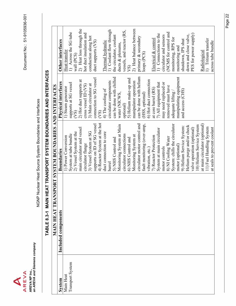
8.3 MAIN HEAT TRANSPORT SYSTEM
The main function of the Main Heat Transport System (MHTS) is to transfer heat from the reactor core to the secondary loop heat transfer system. The heat transfer fluid, helium, flows downward through the reactor core and out through the hot duct, see Figure 8.3-1. It flows from the hot duct into the SG upper plenum and is channeled over the SG tubes via the inner and outer shroud. After flowing across the SG tubes, the cooled helium flows along the annulus formed by the SG vessel and the outer shroud up to the main circulator. The main circulator forces the cooled helium through the annulus formed by the hot duct and the cross vessel. It then flows upward along the core barrel where it turns direction in the upper reactor plenum and flows back down into the reactor core. The flow path remains the same for each loop. There is a check valve just upstream of the circulator to prevent unwanted helium circulation. The major components of the Main Heat Transport System are the hot duct, steam generator, main helium circulator with check valve, all items such as the plenums that direct helium flow through the steam generator vessel, and supports for the items listed. The physical boundary of the system is the interface between supports and the permanently affixed features of the pressure containing vessel. See Table 8.3-1 for boundaries and interfaces.

Document No.: 51-9105936-001 AREVA NP Inc., an AREVA and Siemens company
NGNP Nuclear Heat Source System Boundaries and Interfaces
Page 21
Figure 8.3-1 MAIN HEAT TRANSPORT SYSTEM FLOW PATH
D
ocum
ent N
o.:
51-9
1059
36-0
01
AR
EVA
NP
Inc.
, an
AR
EVA
and
Sie
men
s co
mpa
nyN
GN
P N
ucle
ar H
eat S
ourc
e S
yste
m B
ound
arie
s an
d In
terfa
ces
P
age
22
TAB
LE 8
.3-1
MA
IN H
EAT
TRA
NSP
OR
T SY
STEM
BO
UN
DA
RIE
S A
ND
INTE
RFA
CES
MA
IN H
EA
T T
RA
NSP
OR
T S
YST
EM
BO
UN
DA
RIE
S A
ND
INT
ER
FAC
ES
Syst
em
Incl
uded
com
pone
nts
Bou
ndar
ies
Phys
ical
inte
rfac
es
Oth
er in
terf
aces
M
ain
Hea
t Tr
ansp
ort S
yste
m
1) P
ower
Con
vers
ion
Syst
em a
t tub
e bu
ndle
2)
Ves
sel S
yste
m a
t the
m
ain
circ
ulat
or a
nd v
esse
l ci
rcul
ator
flan
ge
3) V
esse
l Sys
tem
at S
G
supp
orts
on
ID o
f SG
ves
sel
4) R
eact
or S
yste
m a
t the
hot
du
ct c
onne
ctio
n to
cor
e ba
rrel
5)
NH
S C
ontro
l and
M
onito
ring
Syst
em a
t Mai
n ci
rcul
ator
con
nect
ions
6)
NH
S C
ontro
l and
M
onito
ring
Syst
em a
t ci
rcul
ator
mot
or c
ontro
l and
fa
ult m
onito
ring
(ove
r-am
p,
vibr
atio
n, e
tc.)
7) R
eact
or P
rote
ctio
n Sy
stem
at m
ain
circ
ulat
or
mot
or c
ontro
ls
8) N
I Coo
ling
Wat
er
Syst
em: c
hills
the
circ
ulat
or
mot
or (o
ptio
nal)
9) H
eliu
m S
ervi
ce S
yste
m:
Hel
ium
pur
ge a
nd/o
r che
ck
valv
e op
erat
ion
(opt
iona
l) 10
) Hel
ium
Ser
vice
Sys
tem
at
mai
n ci
rcul
ator
(opt
iona
l) 11
) Fue
l Han
dlin
g Sy
stem
at
seal
s to
prev
ent c
oola
nt
1) S
team
gen
erat
or
supp
orts
at S
G v
esse
l (V
S)
2) H
ot d
uct s
uppo
rts a
t cr
oss v
esse
l ID
(VS)
3)
Mai
n ci
rcul
ator
at
conn
ectio
n to
SG
ves
sel
(VS)
4)
The
coo
ling
of
circ
ulat
or c
ompo
nent
s ca
n be
don
e w
ith c
hille
d w
ater
(NIC
WS,
op
tiona
l) 5)
Hel
ium
mak
e-up
and
m
anip
ulat
or o
pera
tion
can
be d
one
with
hel
ium
(H
SS, o
ptio
nal)
6) H
ot d
uct c
onne
ctio
n at
cor
e ba
rrel
(RS)
7)
All
equi
pmen
t tha
t m
ay n
eed
repl
aced
or
rem
oved
mus
t hav
e ad
equa
te li
fting
/ m
anip
ulat
ing
equi
pmen
t an
d ac
cess
(CH
S)
Hea
t tra
nsfe
r 1)
A
cros
s the
SG
tube
w
all (
PCS)
2)
H
eat l
oss t
hrou
gh th
e ho
t duc
t ins
ulat
ion
and
cond
uctio
n al
ong
hot
duct
supp
orts
(VS)
Th
erm
al h
ydra
ulic
1)
Coo
lant
flow
thro
ugh
the
circ
ulat
or, c
oola
nt
duct
s & p
lenu
ms,
vess
els,
and
reac
tor (
RS,
V
S)
2) H
eat b
alan
ce b
etw
een
prim
ary
& se
cond
ary
loop
s (PC
S)
Elec
trica
l & c
ontro
l 1)
C
onne
ctio
ns to
the
circ
ulat
or a
nd se
nsor
s (N
CM
S fo
r con
trol a
nd
mon
itorin
g, R
PS fo
r m
onito
ring
and
shut
dow
n, IP
S sh
ut
dow
n an
d cl
ose
valv
e,
PES
for p
ower
supp
ly)
Rad
iolo
gica
l 1)
Tr
itium
tran
sfer
ac
ross
tube
bun
dle

D
ocum
ent N
o.:
51-9
1059
36-0
01
AR
EVA
NP
Inc.
, an
AR
EVA
and
Sie
men
s co
mpa
nyN
GN
P N
ucle
ar H
eat S
ourc
e S
yste
m B
ound
arie
s an
d In
terfa
ces
P
age
23
MA
IN H
EA
T T
RA
NSP
OR
T S
YST
EM
BO
UN
DA
RIE
S A
ND
INT
ER
FAC
ES
Syst
em
Incl
uded
com
pone
nts
Bou
ndar
ies
Phys
ical
inte
rfac
es
Oth
er in
terf
aces
lo
ss
12) N
HS
Inve
stm
ent
Prot
ectio
n Sy
stem
at
circ
ulat
or c
ontro
ls to
shut
do
wn
circ
ulat
or a
nd c
lose
va
lve
13) P
lant
Ele
ctric
al S
yste
m
at c
onne
ctio
n to
circ
ulat
or
cont
rols
to su
pply
pow
er
St
eam
gen
erat
or
Tube
shee
ts
Tube
bun
dle
Upp
er p
lenu
m w
/ cro
ss d
uct e
lbow
In
ner &
out
er sh
roud
Low
er p
lenu
m
Mai
n he
lium
circ
ulat
or
El
ectri
c m
otor
Impe
ller
M
ain
loop
shut
off v
alve
Hot
duc
t
Inne
r sle
eve
In
sula
tion
Out
er sl
eeve
Duc
t sup
ports

Document No.: 51-9105936-001 AREVA NP Inc., an AREVA and Siemens company
NGNP Nuclear Heat Source System Boundaries and Interfaces
Page 24
8.4 SHUTDOWN COOLING SYSTEM
The purpose of the Shutdown Cooling System (SCS) is to remove heat from the reactor core during shutdown and when the MHTS is not working. This system consists of the shutdown cooling circulator, the shutdown cooling secondary heat removal loop, and the Shutdown Cooling System controls. The primary coolant (helium) is pulled through a heat exchanger by the SCS circulator where heat is rejected to the shutdown cooling water system (SCWS) and expelled to the atmosphere via a second heat exchanger. The SCWS consists of a dedicated self-contained loop for each reactor module. The SCS circulator contains a normally closed shut off valve similar to the check valve used in the main helium circulator. See Figure 8.4-1 below. See Table 8.4-1 for boundaries and interfaces.
Figure 8.4-1 SHUTDOWN COOLING SYSTEM

D
ocum
ent N
o.:
51-9
1059
36-0
01
AR
EVA
NP
Inc.
, an
AR
EVA
and
Sie
men
s co
mpa
nyN
GN
P N
ucle
ar H
eat S
ourc
e S
yste
m B
ound
arie
s an
d In
terfa
ces
P
age
25
TAB
LE 8
.4-1
SH
UTD
OW
N C
OO
LIN
G S
YSTE
M B
OU
ND
AR
IES
AN
D IN
TER
FAC
ES
SHU
TD
OW
N C
OO
LIN
G S
YST
EM
BO
UN
DA
RIE
S A
ND
INT
ER
FAC
ES
Syst
em
Incl
uded
com
pone
nts
Bou
ndar
ies
Phys
ical
inte
rfac
es
Oth
er in
terf
aces
Sh
utdo
wn
Coo
ling
Syst
em
(SC
S)
1)
V
esse
l Sys
tem
at
circ
ulat
or c
onne
ctio
n to
R
PV
2)
Rea
ctor
Sys
tem
at
low
er c
ore
supp
ort
3)
NH
S C
ontro
l and
M
onito
ring
Syst
em a
t co
nnec
tions
to c
ircul
ator
an
d se
nsor
s 4)
N
HS
Inve
stm
ent
Prot
ectio
n Sy
stem
at
conn
ectio
ns to
circ
ulat
or
cont
rols
5)
N
I Coo
ling
Wat
er
Syst
em: p
rovi
des
mot
or
cool
ing
(opt
iona
l)
6)
Hel
ium
Ser
vice
Sys
tem
at
circ
ulat
or (o
ptio
nal)
7)
Si
te &
Civ
il W
orks
at
the
build
ing
/ equ
ipm
ent
inte
rfac
e 8)
Pl
ant E
lect
rical
Sys
tem
at
circ
ulat
or c
ontro
ls fo
r po
wer
supp
ly
1) S
CS
pene
tratio
n in
lo
wer
RPV
hea
d at
at
tach
men
t poi
nt o
f the
SC
S ci
rcul
ator
(VS)
2)
SC
S du
ct c
onne
ctio
n to
the
reac
tor s
uppo
rt st
ruct
ure
(RS)
3)
Con
cret
e em
beds
for
equi
pmen
t pla
cem
ent
(SC
W)
4) L
iftin
g eq
uipm
ent
and
acce
ss m
ust b
e ad
equa
te fo
r rep
air &
re
plac
emen
t (C
HS)
5)
The
coo
ling
of
circ
ulat
or c
ompo
nent
s ca
n be
don
e w
ith c
hille
d w
ater
(NIC
WS,
op
tiona
l) 7)
Hel
ium
mak
e-up
and
m
anip
ulat
or o
pera
tion
can
be d
one
with
hel
ium
(H
SS, o
ptio
nal)
Elec
trica
l & c
ontro
l 1)
C
onne
ctio
n to
the
circ
ulat
or m
otor
, sen
sors
&
bear
ings
(NC
MS
for c
ontro
ls
& m
onito
ring,
IPS
for s
tartu
p w
hen
need
ed, P
ES fo
r el
ectri
cal p
ower
) Th
erm
al h
ydra
ulic
s 1)
C
oola
nt fl
ow p
ath
form
ed
by th
ese
syst
ems (
VS,
RS)
2)
H
eat b
alan
ce b
etw
een
prim
ary
and
seco
ndar
y lo
ops
of th
e (M
HTS
) H
eat t
rans
fer
1) A
cros
s hea
t exc
hang
er h
eat
trans
fer s
urfa
ces f
rom
prim
ary
cool
ant (
MH
TS)
Rad
iolo
gica
l 1)
Mon
itor S
CW
S he
at tr
ansf
er
fluid
Sh
utdo
wn
cool
ing
circ
ulat
or
Mot
or
Sh
utdo
wn
cool
ing
loop
shut
-off
val
ve
Shut
dow
n co
olin
g he
at e
xcha
nger
Shut
dow
n co
olin
g w
ater
syst
em

Document No.: 51-9105936-001 AREVA NP Inc., an AREVA and Siemens company
NGNP Nuclear Heat Source System Boundaries and Interfaces
Page 26
8.5 REACTOR CAVITY COOLING SYSTEM
The Reactor Cavity Cooling System (RCCS) performs two functions. It keeps the concrete of the reactor cavity within allowable limits and removes decay heat from the reactor core when neither the MHTS nor the SCS are working.
The cavity walls and floor are lined with water panels that form an air to water heat exchanger. The heated water in the chambers flow to a water storage tank and is constantly replaced by cooler water. There are two separate complete systems planned for each reactor cavity. The water in each storage tank is cooled by a dedicated cooling system. In the event that the dedicated tank cooling system is not functioning, the cavity cooling system rejects heat by vaporizing the water in the holding tanks.
When neither the MHTS nor the SCS are working, decay heat form the core is removed by conduction through the outer graphite reflectors and by radiation and natural convection from the un-insulated portions of the RPV to the water chambers lining the cavity walls and floor. The heat is then removed as described above. For the purpose of this discussion, the un-insulated portion of the RPV is the cylindrical segment between the upper and lower head. See Table 8.5-1 for boundaries and interfaces.
Figure 8.5-1 REACTOR CAVITY COOLING SYSTEM SCHEMATIC
Water Storage and Heat Exchangers
Natural Convection Flow
Forced flow
Panel wall Cavity Cooler
Inlet Headers
Outlet Headers
Reactor Vessel
Dedicated cooling system

D
ocum
ent N
o.:
51-9
1059
36-0
01
AR
EVA
NP
Inc.
, an
AR
EVA
and
Sie
men
s co
mpa
nyN
GN
P N
ucle
ar H
eat S
ourc
e S
yste
m B
ound
arie
s an
d In
terfa
ces
P
age
27
TAB
LE 8
.5-1
RC
CS
BO
UN
DA
RIE
S A
ND
INTE
RFA
CES
RC
CS
BO
UN
DA
RIE
S A
ND
INT
ER
FAC
ES
Syst
em
Incl
uded
com
pone
nts
Bou
ndar
ies
Phys
ical
inte
rfac
es
Oth
er in
terf
aces
R
eact
or C
avity
C
oolin
g Sy
stem
(R
CC
S)
1)
N
HS
Con
trol a
nd
Mon
itorin
g Sy
stem
at
sens
ors
2)
Site
& C
ivil
Wor
ks a
t th
e bu
ildin
g / e
quip
men
t in
terf
ace
3)
R
adio
activ
e W
aste
and
D
econ
tam
inat
ion
Syst
em
(liqu
id) a
t RPV
cav
ity d
rain
to
sum
p
4)
Plan
t Ele
ctric
al S
yste
m
at ta
nk c
hille
r sys
tem
pow
er
conn
ectio
ns
5)
NH
S C
ontro
l and
M
onito
ring
Syst
em a
t se
nsor
s in
tank
chi
ller
syst
em
1) C
oncr
ete
embe
ds fo
r al
l equ
ipm
ent s
uppo
rts
& b
uild
ing
stee
l as
need
ed (S
CW
)
Hea
t tra
nsfe
r 1)
Th
is sy
stem
is to
pr
even
t ove
rhea
ting
RPV
ca
vity
con
cret
e fr
om h
eat
gene
rate
d by
RPV
(VS,
SC
W)
Ther
moh
ydra
ulic
1)
H
eat l
oad
from
RPV
to
the
RC
CS
(VS)
R
adio
logi
cal
1) M
onito
ring
RC
CS
cool
ant a
nd ta
nk c
hille
r co
olan
t. El
ectri
cal &
con
trol
1) P
ower
con
nect
ion
to
equi
pmen
t and
con
trols
(P
ES)
2) M
onito
ring
stat
us se
nsor
co
nnec
tions
(NC
MS)
RC
CS
cavi
ty b
ase
cool
ing
pane
ls &
pip
ing
RC
CS
verti
cal c
oolin
g pa
nels
& p
ipin
g
C
oolin
g w
ater
tank
s
Ta
nk c
hille
r sys
tem
R
CC
S co
olin
g w
ater
che
mis
try

Document No.: 51-9105936-001 AREVA NP Inc., an AREVA and Siemens company
NGNP Nuclear Heat Source System Boundaries and Interfaces
Page 28
8.6 FUEL HANDLING SYSTEM
The purpose of the Fuel Handling System is to replace used fuel and reflector elements within the reactor core. First, new fuel and reflector elements are moved to the fuel storage wells, see Figure 8.6-2. Then, the used elements are un-stacked from the core and placed into the storage well one sector at a time. Each element is grappled by the fuel handling machine using a handling feature like that shown in Figure 8.6-1. The element is then transferred vertically from the core through the vessel NCA openings. The fuel is then transferred to fuel transfer equipment which transports the elements to the fuel storage wells. The spent fuel and reflector elements are sent for processing in the Spent Fuel Storage and Cooling System. The process is then reversed to restack the partially spent elements using new elements where needed. See Table 8.6-1 for boundaries and interfaces.
Figure 8.6-1 FUEL HANDLING MACHINE GRAPPLING FEATURE

Document No.: 51-9105936-001 AREVA NP Inc., an AREVA and Siemens company
NGNP Nuclear Heat Source System Boundaries and Interfaces
Page 29
Figure 8.6-2 FUEL HANDLING SYSTEM PLAN VIEW
The Figure above depicts a multiple (4) module configuration. The number of modules may vary.

D
ocum
ent N
o.:
51-9
1059
36-0
01
AR
EVA
NP
Inc.
, an
AR
EVA
and
Sie
men
s co
mpa
nyN
GN
P N
ucle
ar H
eat S
ourc
e S
yste
m B
ound
arie
s an
d In
terfa
ces
P
age
30
TAB
LE 8
.6-1
FU
EL H
AN
DLI
NG
SYS
TEM
BO
UN
DA
RIE
S A
ND
INTE
RFA
CES
FUE
L H
AN
DL
ING
SY
STE
M B
OU
ND
AR
IES
AN
D IN
TE
RFA
CE
S Sy
stem
In
clud
ed c
ompo
nent
s B
ound
arie
s Ph
ysic
al in
terf
aces
O
ther
inte
rfac
es
Fuel
Han
dlin
g Sy
stem
1)
Site
& C
ivil
Wor
ks a
t th
e bu
ildin
g / e
quip
men
t in
terf
ace
2)
R
eact
or S
yste
m a
t re
flect
or a
nd fu
el e
lem
ents
3)
V
esse
l Sys
tem
at a
cces
s (N
CA
) ope
ning
s 4)
Pl
ant E
lect
rical
Sys
tem
at
equ
ipm
ent m
otor
s &
cont
rol c
onne
ctio
n 5)
Sp
ent F
uel S
tora
ge a
nd
Coo
ling
Syst
em a
t fue
l ha
nd-o
ff in
the
fuel
stor
age
wel
ls
6)
Com
pone
nt H
andl
ing
Syst
em: u
sed
to m
ove
and
inst
all e
quip
men
t 7)
M
ain
Hea
t Tra
nspo
rt Sy
stem
at s
eals
to p
reve
nt
cool
ant l
oss
1)
At N
CA
ves
sel
pene
tratio
ns (V
S)
2)
Rea
ctor
upp
er
plen
um sh
roud
acc
ess
for f
uel h
andl
ing
equi
pmen
t (R
S)
3)
Fuel
and
refle
ctor
el
emen
ts w
ith fu
el
hand
ling
equi
pmen
t (R
S)
4)
Fuel
stor
age
wel
l w
ith fu
el h
andl
ing
equi
pmen
t (SF
SS)
5)
Con
cret
e st
ruct
ural
em
beds
& b
uild
ing
stee
l (S
CW
) 6)
Eq
uipm
ent m
ust b
e ha
ndle
d w
ith th
e C
ompo
nent
Han
dlin
g Eq
uipm
ent (
CH
S)
Elec
trica
l & c
ontro
l 1)
Pow
er c
onne
ctio
n to
eq
uipm
ent a
nd c
ontro
ls
(PES
) R
adio
logi
cal
1)
Rad
iatio
n sh
ield
ing
for w
orke
rs d
urin
g al
l as
pect
s of f
uel m
ovem
ent
and
any
pote
ntia
l eq
uipm
ent r
epai
r sc
enar
io
2)
Con
trol o
f co
ntam
inat
ion
on
equi
pmen
t 3)
C
ritic
ality
con
trol o
f fu
el e
lem
ents
Fu
el h
andl
ing
cont
rol s
tatio
n
Fu
el h
andl
ing
mac
hine
Fu
el e
leva
tor
Fuel
serv
er

Document No.: 51-9105936-001 AREVA NP Inc., an AREVA and Siemens company
NGNP Nuclear Heat Source System Boundaries and Interfaces
Page 31
8.7 SPENT FUEL STORAGE AND COOLING SYSTEM
This system receives the irradiated fuel and reflector elements from the reactor core, packages them into containers, and provides intermediate storage until they are shipped off. The elements are removed from the core and placed into the fuel storage wells as described in Section 8.6. The spent elements are transferred to the fuel canning facility where they are sealed into containers. The containers will then be relocated to a spent fuel cooling facility where it will be stored until their decay heat has decreased to the point that they can be safely loaded into large capacity shipping and storage cask. The spent fuel elements are stored in tubes surrounded by water to remove the decay heat. The cooling water used for decay heat removal is part of the NI Cooling Water System. As an option, a long term dry cask storage facility could be added to store the shipping and storage casks on site. This option could be added at a later date. See Table 8.7-1 for boundaries and interfaces.

D
ocum
ent N
o.:
51-9
1059
36-0
01
AR
EVA
NP
Inc.
, an
AR
EVA
and
Sie
men
s co
mpa
nyN
GN
P N
ucle
ar H
eat S
ourc
e S
yste
m B
ound
arie
s an
d In
terfa
ces
P
age
32
TAB
LE 8
.7-1
SPE
NT
FUEL
STO
RA
GE
AN
D C
OO
LIN
G S
YSTE
M B
OU
ND
AR
IES
AN
D IN
TER
FAC
ES
SPE
NT
FU
EL
ST
OR
AG
E A
ND
CO
OL
ING
SY
STE
M B
OU
ND
AR
IES
AN
D IN
TE
RFA
CE
S Sy
stem
In
clud
ed c
ompo
nent
s B
ound
arie
s Ph
ysic
al in
terf
aces
O
ther
inte
rfac
es
Spen
t Fue
l Sto
rage
an
d C
oolin
g Sy
stem
1)
Plan
t Ele
ctric
al S
yste
m
at e
quip
men
t & c
ontro
ls
2)
Site
& C
ivil
Wor
ks a
t th
e bu
ildin
g / e
quip
men
t in
terf
ace
3)
Rad
ioac
tive
Was
te a
nd
Dec
onta
min
atio
n Sy
stem
(li
quid
) at s
tora
ge w
ell d
rain
to
sum
p
4)
Fuel
Han
dlin
g Sy
stem
at
exc
hang
e po
int b
etw
een
syst
ems (
fuel
stor
age
wel
l) 5)
N
ew F
uel H
andl
ing
and
Stor
age
Syst
em a
t han
d-of
f po
int w
ith S
pent
Fue
l St
orag
e an
d C
oolin
g Sy
stem
6)
N
HS
Con
trol a
nd
Mon
itorin
g Sy
stem
at
devi
ce c
onne
ctio
n
1) C
oncr
ete
stru
ctur
al e
mbe
ds
& b
uild
ing
stee
l (SC
W)
2) I
nter
face
bet
wee
n eq
uipm
ent
and
the
Com
pone
nt H
andl
ing
Syst
em e
quip
men
t suc
h as
the
over
head
cra
ne. (
CH
S)
3) T
he fu
el st
orag
e w
ell m
ust
acco
mm
odat
e th
e fu
el h
andl
ing
equi
pmen
t for
pic
k-up
and
off
-lo
adin
g of
fuel
and
refle
ctor
el
emen
ts (F
HS,
NFH
S)
4) I
nter
face
with
Com
pone
nt
Han
dlin
g Eq
uipm
ent t
o en
sure
fe
asib
le re
pair
& re
plac
emen
t (C
HS)
5)
Rea
ctor
cor
e fu
el a
nd
refle
ctor
ele
men
ts (R
S)
6) I
nter
face
with
radi
olog
ical
w
aste
at s
yste
m d
rain
pip
e co
nnec
tion
(RW
DS)
Rad
iolo
gica
l 1)
C
ontro
l of c
onta
min
atio
n
2)
Rad
iatio
n sh
ield
ing
for
wor
kers
at a
ll po
ints
of s
yste
m
3)
Crit
ical
ity c
ontro
l of s
pent
fuel
4)
R
adia
tion
and
cont
amin
atio
n m
onito
ring
at se
lect
poi
nts
thro
ugho
ut th
e sy
stem
El
ectri
cal &
con
trol
1)
Pow
er c
onne
ctio
n to
syst
em
equi
pmen
t and
con
trols
(NC
MS
for m
onito
ring,
PES
for p
ower
su
pply
) Th
erm
al h
ydra
ulic
s 1)
Dec
ay h
eat f
rom
spen
t fue
l pr
ovid
es a
hea
t loa
d to
the
(NIC
WS)
2)
Dec
ay h
eat f
rom
spen
t fue
l pr
ovid
es a
hea
t loa
d to
the
(NIH
VA
C)
Fu
el st
orag
e w
ell
Spen
t fue
l can
ning
faci
lity
Spen
t fue
l coo
ling
syst
em
Spen
t fue
l cas
k lo
adin
g fa
cilit
y

Document No.: 51-9105936-001 AREVA NP Inc., an AREVA and Siemens company
NGNP Nuclear Heat Source System Boundaries and Interfaces
Page 33
8.8 NEW FUEL HANDLING AND STORAGE SYSTEM
The purpose of the New Fuel Handling and Storage System is to receive and inspect new fuel and reflector elements. Then the elements are delivered to the fuel storage well (see Figure 8.6-2). The new elements are then installed into the reactor core using the Fuel Handling System. The new fuel elements would be transported to the fuel storage well via the same transport equipment used to move the spent elements from the fuel storage well to the fuel canning facility. See Table 8.8-1 for boundaries and interfaces.
TABLE 8.8-1 NEW FUEL HANDLING AND STORAGE SYSTEM BOUNDARIES AND INTERFACES
NEW FUEL HANDLING AND STORAGE SYSTEM BOUNDARIES AND INTERFACES System Included
components Boundaries Physical interfaces Other interfaces
New Fuel Handling and Storage System
TBD 1) Spent Fuel Handling System at hand-off point of new elements to the fuel transport equipment of the spent Fuel Handling System 2) Plant Electrical System at power connection to equipment & controls 3) Site & Civil Works at the building /equipment interface
1) Interface with structural embeds & building steel (SCW) 2) Interface with spent fuel handling equipment at hand-off point of new elements (SFSS) 3) Interface with Component Handling Equipment to ensure feasible repair & replacement of equipment (CHS) 4) Reactor fuel and reflector elements at handling features of the elements (RS)
Radiological 1) Radiation shielding for workers 2) Criticality control Electrical & control 1) Power connection to system equipment and controls (PES)

Document No.: 51-9105936-001 AREVA NP Inc., an AREVA and Siemens company
NGNP Nuclear Heat Source System Boundaries and Interfaces
Page 34
8.9 HELIUM SERVICE SYSTEM
The Helium Service System purifies the primary coolant and maintains the correct coolant chemistry. The recycled coolant is compressed and transferred to helium storage tanks. The system helps control primary coolant pressure and replaces small quantities of helium lost to leakage. The helium is returned back into the system as a purge gas at specific points of the Main Heat Transport System. The purification system components can be modular to allow real time repair and replacement. See Table 8.9-1 for boundaries and interfaces.
TABLE 8.9-1 HELIUM SERVICE SYSTEM BOUNDARIES AND INTERFACES
HELIUM SERVICE SYSTEM BOUNDARIES AND INTERFACES System Included
components Boundaries Physical interfaces Other interfaces
Helium Service System
TBD 1) NI Cooling Water System at equipment connection 2) Main Heat Transport System at main circulator (optional) 3) Shutdown Cooling System at the SCS circulator (optional) 4) Vessel System at penetration nozzles 5) NHS Control and Monitoring System at device connection 6) Plant Electrical System at equipment power connection 7) Site & Civil Works at the building /equipment interface 8) NHS Control and Monitoring System at sensor connections for HSS monitoring
1) Main He circulator for possible valve actuation (MHTS) 2) Shutdown He circulator for possible valve actuation (SCS) 3) RPV penetration nozzles for make-up (VS) 4) Structural concrete embeds & building steel (SCW) 5) Chilled water to equipment for cooling (NICWS)
Radiological 1) Control of contamination and possibly shielding for workers from irradiated particulates removed from the helium Electrical & control 1) Electrical power and sensor connections (NCMS for monitoring, PES for power input) Thermal hydraulics 3) Cooled helium added to Main Heat Transport System coolant (MHTS) 4) NI Cooling Water System water is used to cool HSS equipment (NICWS) Heat transfer 1) Cooled helium in injected into the primary coolant stream cools the vessel nozzle (VS)

Document No.: 51-9105936-001 AREVA NP Inc., an AREVA and Siemens company
NGNP Nuclear Heat Source System Boundaries and Interfaces
Page 35
8.10 NI HVAC SYSTEM
The Nuclear Island Heating, Ventilation, and Air Conditioning System (NIHVAC) is responsible for the overall HVAC of the NI. It is composed of several discrete systems for different areas including clean and potentially contaminated areas. The system is made up of conventional industrial equipment. The system will also help remove contamination from the air. The systems shall be designed to maintain appropriate temperatures for personnel and equipment. See Table 8.10-1 for boundaries and interfaces.
TABLE 8.10-1 NI HVAC SYSTEM BOUNDARIES AND INTERFACES
NI HVAC SYSTEM BOUNDARIES AND INTERFACES System Included
components Boundaries Physical interfaces Other interfaces
NI HVAC System
TBD General Boundaries correspond to the specific areas being ventilated. Specific boundaries conform to the actual HVAC equipment boundaries up to the air intake and exhaust point. Detailed boundaries will be defined as the design progresses. 1) Plant Electrical System at equipment connection 2) NHS Control and Monitoring System at device connection 3) Site & Civil Works at the building / equipment interface 4) NI Cooling Water System at air chillers (optional)
1) Concrete structural embeds & building steel (SCW) 2) Chilled water to air handlers (NICWS)
Thermal hydraulics 1) The NIHVAC system is used to cool the NCA housings (VS) 2) Decay heat from spent fuel provides a heat load to the NIHVAC system (SFSS) Electrical & control 1) Power connection for system equipment (PES for power input, NCMS for monitoring system) Radiological 1) Control of contamination and dose from potentially contaminated system filters 2) Filtering air to trap some radioactive particulates

Document No.: 51-9105936-001 AREVA NP Inc., an AREVA and Siemens company
NGNP Nuclear Heat Source System Boundaries and Interfaces
Page 36
8.11 PLANT ELECTRICAL SYSTEM
The Plant Electrical System (PES) consists of four subsystems, the plant AC electrical system (PACS), the Plant Essential AC Electrical System (EACS), Plant DC Electrical System (PDCS), and Plant Essential DC Electrical System (EDCS). The PES boundaries are the low voltage bushings of the unit transformers and the high voltage bushings of the unit startup auxiliary transformers. See Table 8.11-1 for boundaries and interfaces.
Major distribution equipment of the PACS include the unit and startup auxiliary transformers, isolated phase bus duct, switchgear, unit substations, motor control centers, and distribution panel boards. The components are located as close to the point of utilization as possible.
When the plant is on-line, the normal source of power is the unit generator. When the plant is shut down or the normal power source is unavailable, power is delivered from offsite via the switchyard and is capable of starting and running all normal and essential loads.
The Plant AC Electrical System (PACS) delivers power generated by the plant offsite to the transmission network through the unit transformer(s) and receives power from the network through the unit startup auxiliary transformer(s).
The Essential AC Electrical System (EACS) includes a plant uninterruptible power (PUP) supply with capacity to supply all control, instrumentation, and plant protection AC loads which must not lose power via redundant channels. There is one PUP per unit and is powered by a dedicated essential DC electrical system. The PACS supplies emergency AC/DC lighting for all areas needed for safe shutdown and fire fighting and access/egress routes thereto. The EACS supplies emergency AC lighting for the control room.
The Plant DC Electrical System (PDCS) supplies DC voltage to the plant control and instrumentation loads. The system includes storage batteries, battery chargers, and distribution switchgear.
The Essential DC Electrical System (EDCS) supplies DC voltage to the “Safety Related” DC plant loads. The system includes storage batteries, battery chargers, and distribution switchgear. The EDCS power supply is fully independent of other modules.

D
ocum
ent N
o.:
51-9
1059
36-0
01
AR
EVA
NP
Inc.
, an
AR
EVA
and
Sie
men
s co
mpa
nyN
GN
P N
ucle
ar H
eat S
ourc
e S
yste
m B
ound
arie
s an
d In
terfa
ces
P
age
37
TAB
LE 8
.11-
1 P
LAN
T EL
ECTR
ICA
L SY
STEM
BO
UN
DA
RIE
S A
ND
INTE
RFA
CES
PLA
NT
EL
EC
TR
ICA
L S
YST
EM
BO
UN
DA
RIE
S A
ND
INT
ER
FAC
ES
Syst
em
Incl
uded
com
pone
nts
Bou
ndar
ies
Phys
ical
in
terf
aces
O
ther
inte
rfac
es
Plan
t El
ectri
cal
Syst
em
1)
All
syst
ems u
sing
ele
ctric
al p
ower
: At t
he
conn
ectio
n w
ith e
ach
elec
trica
l dev
ice.
See
inte
rfac
es
for s
yste
m li
st.
2)
Site
& C
ivil
Wor
ks a
t bui
ldin
g / s
uppo
rt in
terf
ace.
3)
Si
te &
Civ
il W
orks
at s
witc
hyar
d: L
ow v
olta
ge
bush
ings
of t
he u
nit t
rans
form
ers (
outb
ound
vol
tage
) 4)
Si
te &
Civ
il W
orks
at s
witc
hyar
d: H
igh
volta
ge
bush
ings
of t
he u
nit s
tartu
p au
xilia
ry tr
ansf
orm
ers
(inbo
und
volta
ge)
1) S
truct
ural
co
ncre
te e
mbe
ds
& b
uild
ing
stee
l (S
CW
)
Elec
trica
l & c
ontro
l 1)
At e
ach
elec
trica
l de
vice
or d
evic
e co
ntro
ller t
o su
pply
po
wer
(RC
CS,
FH
S,
SFSS
, NFH
S, H
SS,
NIH
VA
C, C
HS,
RPS
, IP
S, P
MC
S, S
WD
S)
Pl
ant A
C e
lect
rical
syst
em (P
AC
S) li
nk to
grid
St
artu
p au
xilia
ry tr
ansf
orm
er
U
nit t
rans
form
er
Is
olat
ed p
hase
bus
duc
t
Switc
hgea
r
Uni
t sub
stat
ions
Mot
or c
ontro
l cen
ters
Dis
tribu
tion
pane
l boa
rds
Bac
kup
pow
er g
ener
ator
(s)
Es
sent
ial A
C e
lect
rical
syst
em
Plan
t uni
nter
rupt
ible
pow
er su
pply
Es
sent
ial D
C e
lect
rical
syst
em
St
orag
e ba
tterie
s
B
atte
ry c
harg
ers
Dis
tribu
tion
switc
hgea
r
Plan
t DC
ele
ctric
al sy
stem
St
orag
e ba
tterie
s
B
atte
ry c
harg
ers
Dis
tribu
tion
switc
hgea
r

Document No.: 51-9105936-001 AREVA NP Inc., an AREVA and Siemens company
NGNP Nuclear Heat Source System Boundaries and Interfaces
Page 38
8.12 NI COOLING WATER SYSTEM
The NI Cooling Water System removes heat from plant components such as:
� Helium purification train components
� Main helium circulator
� Nuclear Island HVAC
� Other equipment as necessary
The nuclear island NI Cooling Water System is completely separate from the balance of plant cooling water system to prevent the spread of radiological contamination. Each reactor module cooling water loop consists of pumps, chillers, a surge tank, filter / de-mineralizer train, piping, instruments, and controls as needed. See Table 8.12-1 for boundaries and interfaces.

D
ocum
ent N
o.:
51-9
1059
36-0
01
AR
EVA
NP
Inc.
, an
AR
EVA
and
Sie
men
s co
mpa
nyN
GN
P N
ucle
ar H
eat S
ourc
e S
yste
m B
ound
arie
s an
d In
terfa
ces
P
age
39
TAB
LE 8
.12-
1 N
I CO
OLI
NG
WA
TER
SYS
TEM
BO
UN
DA
RIE
S A
ND
INTE
RFA
CES
NI C
OO
LIN
G W
AT
ER
SY
STE
M B
OU
ND
AR
IES
AN
D IN
TE
RFA
CE
S Sy
stem
In
clud
ed c
ompo
nent
s B
ound
arie
s Ph
ysic
al in
terf
aces
O
ther
inte
rfac
es
NI C
oolin
g W
ater
Sy
stem
The
boun
dary
for a
ll eq
uipm
ent i
nter
face
s are
at
the
conn
ectio
n po
int o
n th
e eq
uipm
ent
1)
NIH
VA
C sy
stem
s at a
ir ha
ndle
rs
2)
Hel
ium
Ser
vice
Sys
tem
at
hel
ium
syst
em c
ompo
nent
3)
M
ain
Hea
t Tra
nsfe
r Sy
stem
at t
he e
quip
men
t co
nnec
tion
4)
Ves
sel S
yste
m a
t the
ve
ssel
pen
etra
tion
5)
Site
& C
ivil
Wor
ks a
t the
bu
ildin
g /e
quip
men
t int
erfa
ce
1)
Hel
ium
serv
ices
pu
rific
atio
n tra
in (H
SS)
2)
Mai
n &
SC
S he
lium
ci
rcul
ator
s (M
HTS
, SC
S)
3)
NIH
VA
C a
ir ha
ndle
rs
(NIH
VA
C)
4)
Con
cret
e st
ruct
ural
em
beds
& b
uild
ing
stee
l (S
CW
)
Ther
mal
hyd
raul
ic
1) T
he N
I Coo
ling
Wat
er
Syst
em p
rovi
des c
oolin
g ca
paci
ty to
equ
ipm
ent i
n th
e fo
llow
ing
syst
ems (
HSS
, M
HTS
, SC
S, N
IHV
AC
) 2)
Dec
ay h
eat f
rom
spen
t fue
l pr
ovid
es a
hea
t loa
d to
the
NI
Coo
ling
Wat
er S
yste
m
(SFS
S)
Rad
iolo
gica
l 1)
Con
tam
inat
ion
cont
rol (
NI
syst
em o
nly)
El
ectri
cal &
con
trol
1) P
ower
con
nect
ion
for
syst
em e
quip
men
t (PE
S)
Pu
mp(
s)
C
hille
r(s)
Surg
e ta
nk
Fi
lter /
de-
min
eral
izer
trai
n
Pipi
ng
In
stru
men
tatio
n
Con
trols

Document No.: 51-9105936-001 AREVA NP Inc., an AREVA and Siemens company
NGNP Nuclear Heat Source System Boundaries and Interfaces
Page 40
8.13 COMPONENT HANDLING SYSTEM
Maintenance and repair of the NHS requires lifting and handling equipment for all components that are expected to be replaced or moved. This handling equipment includes cranes, special temporary handling/manipulating equipment, temporary equipment storage areas, building access for replacement components, and interface with external transportation facilities. A “flight path” and temporary resting area will be developed for each item expected to be replaced. Floor loading shall be considered where needed along the flight path. See Table 8.13-1 for boundaries and interfaces.

D
ocum
ent N
o.:
51-9
1059
36-0
01
AR
EVA
NP
Inc.
, an
AR
EVA
and
Sie
men
s co
mpa
nyN
GN
P N
ucle
ar H
eat S
ourc
e S
yste
m B
ound
arie
s an
d In
terfa
ces
P
age
41
TAB
LE 8
.13-
1 C
OM
PON
ENT
HA
ND
LIN
G S
YSTE
M B
OU
ND
AR
IES
AN
D IN
TER
FAC
ES
CO
MPO
NE
NT
HA
ND
LIN
G S
YST
EM
BO
UN
DA
RIE
S A
ND
INT
ER
FAC
ES
Syst
em
Incl
uded
com
pone
nts
Bou
ndar
ies
Phys
ical
inte
rfac
es
Oth
er in
terf
aces
C
ompo
nent
H
andl
ing
Syst
em
1)
R
eact
or S
yste
m a
t el
emen
ts a
nd c
ompo
nent
s re
quire
d to
be
rem
oved
2)
Si
te &
Civ
il W
orks
at
the
build
ing
/ sup
port
inte
rfac
e 3)
Pl
ant E
lect
rical
Sys
tem
at
the
equi
pmen
t con
nect
ion
4)
Fuel
Han
dlin
g Sy
stem
: m
ust b
e ab
le to
man
ipul
ate
& in
stal
l thi
s equ
ipm
ent
5)
The
Com
pone
nt
Han
dlin
g Eq
uipm
ent
boun
dary
is li
mite
d to
the
poin
t at w
hich
mob
ile
equi
pmen
t can
acc
ess t
he
inte
nded
load
. 6)
Fu
el H
andl
ing
Syst
em
is in
stal
led
and
man
euve
red
by C
ompo
nent
Han
dlin
g Sy
stem
equ
ipm
ent
1)
Mus
t lift
and
m
anip
ulat
e th
e Fu
el
Han
dlin
g Sy
stem
eq
uipm
ent (
FHS)
2)
M
ust l
ift a
nd/o
r m
anip
ulat
e sp
ecifi
c N
HS
equi
pmen
t req
uirin
g sp
ecia
l han
dlin
g or
lif
ting
capa
bilit
ies.
Equi
pmen
t lis
t to
be
deve
lope
d. (V
S, R
S,
MH
TS, S
CS,
RW
DS)
3)
Si
te &
Civ
il W
orks
at
all
tem
pora
ry re
stin
g lo
catio
ns fo
r com
pone
nts
and
thei
r lift
rigg
ing
(SC
W)
Elec
trica
l & c
ontro
l 1)
Pow
er c
onne
ctio
n fo
r sy
stem
equ
ipm
ent (
PES)
C
ore
serv
ice
tool
s
A
uxili
ary
serv
ice
cask
Se
rvic
e to
ols f
or R
eact
or S
yste
m
Res
erve
shut
dow
n va
cuum
tool
N
eutro
n de
tect
or se
rvic
e eq
uipm
ent
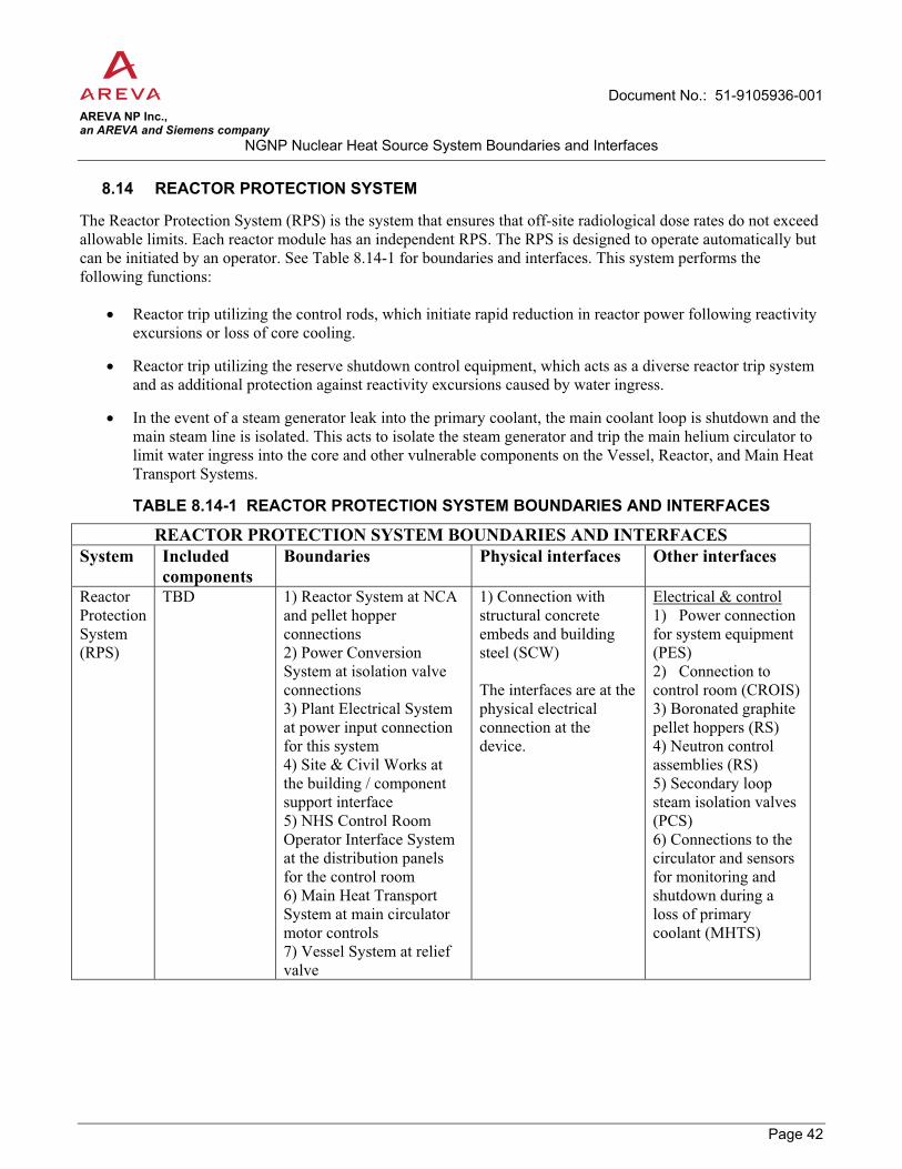
Document No.: 51-9105936-001 AREVA NP Inc., an AREVA and Siemens company
NGNP Nuclear Heat Source System Boundaries and Interfaces
Page 42
8.14 REACTOR PROTECTION SYSTEM
The Reactor Protection System (RPS) is the system that ensures that off-site radiological dose rates do not exceed allowable limits. Each reactor module has an independent RPS. The RPS is designed to operate automatically but can be initiated by an operator. See Table 8.14-1 for boundaries and interfaces. This system performs the following functions:
� Reactor trip utilizing the control rods, which initiate rapid reduction in reactor power following reactivity excursions or loss of core cooling.
� Reactor trip utilizing the reserve shutdown control equipment, which acts as a diverse reactor trip system and as additional protection against reactivity excursions caused by water ingress.
� In the event of a steam generator leak into the primary coolant, the main coolant loop is shutdown and the main steam line is isolated. This acts to isolate the steam generator and trip the main helium circulator to limit water ingress into the core and other vulnerable components on the Vessel, Reactor, and Main Heat Transport Systems.
TABLE 8.14-1 REACTOR PROTECTION SYSTEM BOUNDARIES AND INTERFACES
REACTOR PROTECTION SYSTEM BOUNDARIES AND INTERFACES System Included
components Boundaries Physical interfaces Other interfaces
Reactor Protection System (RPS)
TBD 1) Reactor System at NCA and pellet hopper connections 2) Power Conversion System at isolation valve connections 3) Plant Electrical System at power input connection for this system 4) Site & Civil Works at the building / component support interface 5) NHS Control Room Operator Interface System at the distribution panels for the control room 6) Main Heat Transport System at main circulator motor controls 7) Vessel System at relief valve
1) Connection with structural concrete embeds and building steel (SCW) The interfaces are at the physical electrical connection at the device.
Electrical & control 1) Power connection for system equipment (PES) 2) Connection to control room (CROIS) 3) Boronated graphite pellet hoppers (RS) 4) Neutron control assemblies (RS) 5) Secondary loop steam isolation valves (PCS) 6) Connections to the circulator and sensors for monitoring and shutdown during a loss of primary coolant (MHTS)

Document No.: 51-9105936-001 AREVA NP Inc., an AREVA and Siemens company
NGNP Nuclear Heat Source System Boundaries and Interfaces
Page 43
8.15 NHS INVESTMENT PROTECTION SYSTEM
The NHS Investment Protection System (IPS) is designed to limit damage to plant equipment during upsets and events. There is likely one IPS for each reactor module. Like the RPS, the IPS is designed to operate automatically but can be initiated by an operator. See Table 8.15-1 for boundaries and interfaces. The types of functions this system will perform are:
� Steam generator isolation and steam/water dump which limits the quantity of water that can leak into the core and the resulting chemical attack on reactor components.
� Primary coolant pump down, which limits the release of primary coolant and the thermal cycling of reactor components.
� Shutdown Cooling System initiation, which starts the Shutdown Cooling System upon loss of primary coolant , thus reducing thermal cycling of large components.
� Startup control rod insertion at reactor shutdown event.
The IPS may also provide the following investment related plant monitoring functions:
� The Vessel System pressure relief valve closure interlock
� Safety related equipment status and RPS channel readout information displays
� Investment protection equipment status and channel readout information displays
� Post accident monitoring information and displays
� Monitoring to facilitate post transient plant restart
� Helium leak monitoring
� A continuous, dedicated display of a minimum set of plant parameters or derived variables that may be used by the operator during all plant conditions to access plant safety status.

Document No.: 51-9105936-001 AREVA NP Inc., an AREVA and Siemens company
NGNP Nuclear Heat Source System Boundaries and Interfaces
Page 44
TABLE 8.15-1 NHS INVESTMENT PROTECTION SYSTEM BOUNDARIES AND INTERFACES
NHS INVESTMENT PROTECTION SYSTEM BOUNDARIES AND INTERFACES System Included
components Boundaries Physical interfaces Other interfaces
NHS Investment Protection System (IPS)
TBD General note: Boundary of this system is at electrical connection of each device. 1) Reactor System at NCA controls for rod drop at shutdown 2) Vessel System at the pressure relief valve block connections 3) Main Heat Transport System at connections to circulator controls 4) Shutdown Cooling System at connections to circulator controls 5) NHS Control Room Operator Interface System at the distribution panels for the control room 6) Power Conversion System at steam isolation valve 7) Plant Electrical System at power connection for system 8) Site & Civil Works at the building / component support interface. 9) Plant Electrical System at power input connection for this system 10) Steam/Water Dump System at connection to dump valve actuator controls
All electrical interfaces are at the device connection point 1) Connection with structural concrete embeds and building steel (SCW)
Electrical & control 1) Power connection for system equipment (PES) 2) Steam isolation valves for steam dump and isolation (PCS) 3) Vessel System relief valve for coolant pump down (VS) 4) Primary coolant circulator to shut down and close valve (MHTS) 5) Start SCS circulator to cool the reactor core during shutdown (SCS) 6) NCA rod insertion at reactor shutdown (RS) 7) Connection to control room (CROIS) 8) Connection to dump valve actuator control(SWDS)

Document No.: 51-9105936-001 AREVA NP Inc., an AREVA and Siemens company
NGNP Nuclear Heat Source System Boundaries and Interfaces
Page 45
8.16 NHS CONTROL AND MONITORING SYSTEM
The NHS Control and Monitoring System (NCMS) provides direct interface to all plant actuators and sensors to perform plant control functions within the Nuclear Island (NI) and the Power Conversion System (PCS). Plant level load allocation is performed by the NCMS. Each reactor module can be controlled independently. See Table 8.16-1 for boundaries and interfaces.
TABLE 8.16-1 NCMS BOUNDARIES AND INTERFACES
NCMS BOUNDARIES AND INTERFACES System Included
components Boundaries Physical interfaces Other interfaces
NHS Control and monitoring System (NCMS)
TBD 1) The boundary of this system is at electrical connection of each device 2) Spent Fuel Storage and Cooling System at device connection 3) NIHVAC system at device connection 4) Helium Service System at device connection 5) Reactor Cavity Cooling System at device connection 6) Shutdown Cooling System at device connection 7) Site & Civil Works at the building / component support interface 8) Reactor System at connection to NCAs that enable removal and installation of the NCA 9) Vessel System at pressure relief valve 10) NHS Control and Monitoring System at circulator motor control and fault monitoring (over-amp, vibration, etc.) 11) Plant Electrical System at power input connection for this system 12) Steam/Water Dump System at sensor for leak detection
1) Connection with structural concrete embeds and building steel (SCW)
Electrical & control 1) The NHS Control and Monitoring System interfaces to all plant actuators and sensors. The interface point is considered the connection point nearest the device. (RS, VS, MHTS, SCS, RCCS, SFSS, HSS, NIHVAC, PES, CROIS, SWDS)

Document No.: 51-9105936-001 AREVA NP Inc., an AREVA and Siemens company
NGNP Nuclear Heat Source System Boundaries and Interfaces
Page 46
8.17 CONTROL ROOM AND OPERATOR INTERFACE SYSTEM
The purpose of the Control Room and Operator Interface System (CROIS) is to provide a means for the operator to monitor and control the plant. This system provides the operator with information from the NCMS, IPS, and RPS systems. Similarly, the CROIS allows the operator to transmit instructions to NCMS, IPS, and RPS controllers or directly to individual actuators.
TABLE 8.17-1 CROIS BOUNDARIES AND INTERFACES
CROIS BOUNDARIES AND INTERFACES System Included
components Boundaries Physical interfaces Other interfaces
Control room and operator interface system (CROIS)
TBD 1) The boundary of this system is at the distribution panels for the control room. All physical connections with other systems are made here. 2) Site & Civil Works at the building / component support interface
1) Connection with structural concrete embeds and building steel (SCW)
Electrical & control 1) Power connection for system equipment The control room and operator interface system interfaces with the NCMS, IPS, and RPS systems to provide the operator full control and monitoring of NHS equipment. The interface point for connection to these systems is the distribution panel.
8.18 RADIOACTIVE WASTE AND DECONTAMINATION SYSTEM
The Radioactive Waste and Decontamination System provides a means of managing and where possible, decontamination of all radioactive waste generated within the plant. See Table 8.18-1 for boundaries and interfaces.
All potentially radioactive gas generated in the reactor plant is collected. Gases with low levels of radioactivity may be stored allowing for activity decay to allowable levels prior to release; otherwise, the gasses are processed by the system.
All potentially radioactive liquids are captured and treated based upon the liquid type and the expected level of contamination. Liquids may be treated and prepared for disposal, treated and recycled for use in the plant, or treated and released to the environment.
All potentially radioactive solid waste generated within the reactor plant are captured and treated in this facility except used fuel elements. Compactable items are compacted and made ready for shipment. Liquefied waste are treated and solidified where necessary.
The decontamination services provides the facility and tools required for general decontamination of equipment and components used within the reactor plant.

Document No.: 51-9105936-001 AREVA NP Inc., an AREVA and Siemens company
NGNP Nuclear Heat Source System Boundaries and Interfaces
Page 47
TABLE 8.18-1 RWDS BOUNDARIES AND INTERFACES
RWDS BOUNDARIES AND INTERFACES System Included
components Boundaries Physical interfaces Other interfaces
Radioactive Waste and Decontamination System (RWDS)
TBD 1) The boundaries of this system are at the collection point of the source and the physical boundaries of the processing facility. 2) Site & Civil Works at the building / component support interface 3) Spent Fuel Storage and Cooling System (liquid) at the storage well drain to sump 4) Reactor Cavity Cooling System (liquid) at cavity drain to sump
1) Connection with structural concrete embeds and building steel (SCW) 2) Component Handling System equipment to assure capacity to lift and manipulate RWDS equipment (CHS) 3) Spent Fuel Storage and Cooling System (liquid) at the storage well drain to sump (SFSS) 4) Reactor Cavity Cooling System (liquid) at cavity drain to sump (RS)
Radiological Monitoring of system as deemed necessary by health physics Electrical & control 1) Power connection for system equipment (PES)
8.19 STEAM/WATER DUMP SYSTEM
The STEAM/WATER Dump System is capable of emptying the steam generator’s steam/water inventory in the event of a leak which results in moisture ingress to the primary coolant. It can also be used to drain the steam generator to perform maintenance. The system consists of a redundant valve train connected to the main feedwater line between the SG and the feedwater line isolation valve, see Figure 8.19-1. The boundary of this system is the pipe connection of the first dump valve off of the feedwater line. See Table 8.19-1 for boundaries and interfaces.

Document No.: 51-9105936-001 AREVA NP Inc., an AREVA and Siemens company
NGNP Nuclear Heat Source System Boundaries and Interfaces
Page 48
Figure 8.19-1 STEAM/WATER DUMP SYSTEM
Feedwater
Main Steam
Cold Reheat
Hot Reheat
Isolation Valves
SG vessel
Dump Valves
Dump Tank
to Gaseous Radwaste
to Liquid Radwaste
Water-Steam Dump System
Quench water
Feedwater
Main Steam
Cold Reheat
Hot Reheat
Isolation Valves
SG vessel
Dump Valves
Dump Tank
to Gaseous Radwaste
to Liquid Radwaste
Water-Steam Dump System
Quench water
TABLE 8.19-1 STEAM/WATER DUMP SYSTEM BOUNDARIES AND INTERFACES
STEAM/WATER DUMP SYSTEM BOUNDARIES AND INTERFACES System Included
components Boundaries Physical interfaces Other interfaces
Steam/Water Dump System (SWDS)
Dump valve
1) Power Conversion System at the pipe connections of the first dump valves. 2) Site & Civil Works at the building / component support interface 3) Radioactive Waste and Decontamination System at the pipe connection to the dump tank 4) NI Investment Protection System at valve controls 5) Plant Electrical System at valve actuator 6) NHS Plant Control and Monitoring at sensor for dump valve leak detection
1) Power Conversion System at the pipe connections of the first dump valves. (PCS) 2) Site & Civil Works at the building / component support interface (SCW) 3) Radioactive Waste and Decontamination System at the exhaust/vent pipe connection to the dump tank (RWDS)
Radiological Monitoring of system at the dump tank, dump tank relief, and as deemed necessary by health physics Electrical & control 1) Power connection for dump valves (PES) 2) IPS for valve actuation 3) Sensor for dump valve leak detection (NCMS)
Steam/Water Dump System

Document No.: 51-9105936-001 AREVA NP Inc., an AREVA and Siemens company
NGNP Nuclear Heat Source System Boundaries and Interfaces
Page 49
9.0 REFERENCES
1. AREVA document 51-9103803-000, NGNP Conceptual Design Baseline Document for Conventional Steam Cycle for Process Heat and Cogeneration

D
ocum
ent N
o.:
51-9
1059
36-0
01
AR
EVA
NP
Inc.
, an
AR
EVA
and
Sie
men
s co
mpa
nyN
GN
P N
ucle
ar H
eat S
ourc
e S
yste
m B
ound
arie
s an
d In
terfa
ces
P
age
A-1
APP
END
IX A
: N
HS
SYST
EM B
OU
ND
AR
Y M
ATR
IX
Sec
t. #
1 2
3 4
5 6
7 8
9 10
11
12
13
14
15
16
17
18
19
RS
VS
MH
TS
SCS
RC
CS
FHS
SFSS
N
FHS
HSS
N
I H
VA
C
PES
* N
I CW
S **
C
HS
RPS
IP
S *
NC
MS
* C
RO
IS
RW
DS
SWD
S S C
W
P C
S R
S
� �
�
�
�
� �
�
�
VS
�
� �
�
�
�
� �
�
� M
HTS
�
�
�
�
�
� �
�
�
SCS
� �
�
�
� �
�
R
CC
S
�
�
�
�
FHS
� �
�
�
�
�
�
SF
SS
�
�
�
�
�
�
N
FHS
�
�
�
H
SS
�
� �
� �
�
�
N
IHV
AC
�
�
�
�
PES
*
� �
� �
� �
� �
� �
�
N
ICW
S **
� �
�
�
�
CH
S �
�
�
�
�
RPS
�
� �
�
�
� �
IPS
*
� �
� �
�
�
� �
� N
CM
S *
� �
�
�
�
� �
�
�
�
� �
C
RO
IS
�
� �
�
R
WD
S
�
�
�
�
SWD
S
�
�
�
�
� �
NO
TES
: RE
AD
TA
BLE
FR
OM
LE
FT T
O R
IGH
T. P
ICK
SY
STE
M IN
LE
FT C
OLU
MN
AN
D R
EA
D W
HIC
H S
YS
TEM
S IT
INTE
RFA
CE
S IN
TH
AT
RO
W.
* A
gen
eral
bou
ndar
y ex
ists
for a
ll sy
stem
s usi
ng e
lect
rical
pow
er &
con
trols
whe
re th
e bo
unda
ry is
at t
he p
hysi
cal c
onne
ctio
n at
the
devi
ce.
**
A g
ener
al b
ound
ary
exis
ts a
t the
poi
nt w
here
mob
ile e
quip
men
t can
acc
ess t
he in
tend
ed lo
ad.
***
The
boun
darie
s of t
his s
yste
m a
re a
t the
col
lect
ion
poin
t of t
he so
urce
and
the
phys
ical
bou
ndar
ies o
f the
pro
cess
ing
faci
lity.
R
S R
eact
or S
yste
m
FHS
Fuel
Han
dlin
g Sy
stem
PE
SPl
ant E
lect
rical
Sys
tem
NC
MS
NH
S C
ontro
l and
Mon
itorin
g Sy
stem
V
S V
esse
l Sys
tem
SF
SS
Spen
t Fue
l Sto
rage
and
N
ICW
SN
I Coo
ling
Wat
er S
yste
mC
RO
ISN
HS
Con
trol R
oom
Ope
rato
r Int
erfa
ce
MH
TS
Mai
n H
eat T
rans
port
Syst
em
NFH
S N
ew F
uel H
andl
ing
and
CH
SC
ompo
nent
han
dlin
g sy
s.SC
S Sh
utdo
wn
Coo
ling
Syst
em
HSS
H
eliu
m S
ervi
ce S
yste
mR
PSR
eact
or p
rote
ctio
n sy
stem
RW
DS
Rad
ioac
tive
Was
te a
nd D
econ
tam
inat
ion
S yst
em
RC
CS
Rea
ctor
Cav
ity C
oolin
g Sy
stem
N
IHV
AC
N
I Hea
ting
Ven
tilat
ion
and
Air
Con
ditio
ning
IP
S In
vest
men
t pro
tect
ion
sys.
SWD
S St
eam
/Wat
er D
ump
Syst
em
SCW
Si
te &
Civ
il W
orks
PC
S Po
wer
Con
vers
ion
Syst
em

D
ocum
ent N
o.:
51-9
1059
36-0
01
AR
EVA
NP
Inc.
, an
AR
EVA
and
Sie
men
s co
mpa
nyN
GN
P N
ucle
ar H
eat S
ourc
e S
yste
m B
ound
arie
s an
d In
terfa
ces
P
age
B-1
APP
END
IX B
: N
HS
SYST
EM P
HYS
ICA
L IN
TER
FAC
E M
ATR
IX
Sect
. #
1 2
3 4
5 6
7 8
9 10
11
12
13
14
15
16
17
18
19
RS
VS
MH
TS
SCS
RC
CS
FHS
SFSS
N
FHS
HSS
N
I H
VA
C
PES
NI C
WS
CH
S R
PS
IPS
NC
MS
CR
OIS
R
WD
S S
WD
SS C
W
P C
S R
S
� �
�
� �
�
�
VS
�
� �
�
�
� M
HTS
�
�
�
� �
SCS
� �
�
�
�
�
R
CC
S
�
FHS
� �
�
�
�
SF
SS
�
�
�
�
�
�
N
FHS
�
�
�
�
H
SS
�
� �
�
�
N
IHV
AC
�
�
PES
�
NIC
WS
� �
� �
�
C
HS
� �
� �
�
� �
�
�
R
PS
�
IP
S
�
N
CM
S
�
C
RO
IS
�
R
WD
S �
�
�
�
�
SWD
S
�
� �
NO
TE: R
EA
D T
AB
LE F
RO
M L
EFT
TO
RIG
HT.
PIC
K S
YS
TEM
IN L
EFT
CO
LUM
N A
ND
RE
AD
WH
ICH
SY
STE
MS
IT IN
TER
FAC
ES
IN T
HA
T R
OW
.
PLA
NT
SY
STE
M A
BB
RE
VIA
TIO
N T
AB
LE
RS
Rea
ctor
Sys
tem
FH
S Fu
el H
andl
ing
Syst
em
PES
Plan
t Ele
ctric
al S
yste
m
NC
MS
NH
S C
ontro
l and
Mon
itorin
g Sy
stem
VS
Ves
sel S
yste
m
SFSS
Sp
ent F
uel S
tora
ge a
nd
Coo
ling
Syst
em
NIC
WS
NI C
oolin
g W
ater
Sys
tem
C
RO
IS
NH
S C
ontro
l Roo
m O
pera
tor
Inte
rfac
e Sy
stem
MH
TS
Mai
n H
eat T
rans
port
Syst
em
NFH
S N
ew F
uel H
andl
ing
and
Stor
age
Syst
em
CH
S C
ompo
nent
Han
dlin
g Sy
stem
SCS
Shut
dow
n C
oolin
g Sy
stem
H
SS
Hel
ium
Ser
vice
Sys
tem
R
PS
Rea
ctor
pro
tect
ion
syst
em
RW
DS
Rad
ioac
tive
Was
te a
nd
Dec
onta
min
atio
n Sy
stem
RC
CS
Rea
ctor
Cav
ity C
oolin
g Sy
stem
N
IHV
AC
N
I Hea
ting
Ven
tilat
ion
and
Air
Con
ditio
ning
IP
S N
HS
Inve
stm
ent P
rote
ctio
n Sy
stem
SW
DS
Stea
m/W
ater
Dum
p Sy
stem
SCW
Si
te &
Civ
il W
orks
PC
S Po
wer
Con
vers
ion
Syst
em

D
ocum
ent N
o.:
51-9
1059
36-0
01
AR
EVA
NP
Inc.
, an
AR
EVA
and
Sie
men
s co
mpa
nyN
GN
P N
ucle
ar H
eat S
ourc
e S
yste
m B
ound
arie
s an
d In
terfa
ces
P
age
C-1
APP
END
IX C
: N
HS
SYST
EM E
LEC
TRIC
AL
INTE
RFA
CE
MA
TRIX
Se
ct. #
1
2 3
4 5
6 7
8 9
10
11
12
13
14
15
16
17
18
19
R
S V
S M
HTS
SC
S R
CC
S FH
S SF
SS
NFH
S H
SS
NI
HV
AC
PE
S N
I CW
S C
HS
RPS
IP
S N
CM
S C
RO
IS
RW
DS
SWD
S S C
W
P C
S R
S
� �
�
VS
� �
M
HTS
� �
�
SCS
� �
R
CC
S
�
�
FHS
�
SF
SS
�
�
N
FHS
�
H
SS
�
�
N
IHV
AC
�
�
PES
�
� �
� �
�
�
� �
�
�
NIC
WS
�
C
HS
�
R
PS
�
�
�
�
� IP
S
� �
� �
�
�
�
� N
CM
S
� �
� �
�
�
� �
�
�
�
C
RO
IS
�
� �
R
WD
S
�
SWD
S
�
�
�
NO
TE: R
EA
D T
AB
LE F
RO
M L
EFT
TO
RIG
HT.
PIC
K S
YS
TEM
IN L
EFT
CO
LUM
N A
ND
RE
AD
WH
ICH
SY
STE
MS
IT IN
TER
FAC
ES
IN T
HA
T R
OW
.
PLA
NT
SY
STE
M A
BB
RE
VIA
TIO
N T
AB
LE
RS
Rea
ctor
Sys
tem
FH
S Fu
el H
andl
ing
Syst
em
PES
Plan
t Ele
ctric
al S
yste
m
NC
MS
NH
S Pl
ant C
ontro
l & M
onito
ring
Sys.
VS
Ves
sel S
yste
m
SFSS
Sp
ent F
uel S
tora
ge a
nd
Coo
ling
Syst
em
NIC
WS
NI C
oolin
g W
ater
Sys
tem
C
RO
IS
NH
S C
ontro
l Roo
m O
pera
tor
Inte
rfac
e Sy
stem
MH
TS
Mai
n H
eat T
rans
port
Syst
em
NFH
S N
ew F
uel H
andl
ing
and
Stor
age
Syst
em
CH
S C
ompo
nent
Han
dlin
g Sy
stem
SC
S Sh
utdo
wn
Coo
ling
Syst
em
HSS
H
eliu
m S
ervi
ce S
yste
m
RPS
R
eact
or p
rote
ctio
n sy
stem
R
WD
S R
adio
activ
e W
aste
and
D
econ
tam
inat
ion
Syst
em
RC
CS
Rea
ctor
Cav
ity C
oolin
g Sy
stem
N
IHV
AC
N
I Hea
ting
Ven
tilat
ion
and
Air
Con
ditio
ning
IP
S N
HS
Inve
stm
ent
Prot
ectio
n Sy
stem
SC
W
Site
& C
ivil
Wor
ks
PCS
Pow
er C
onve
rsio
n Sy
stem
SW
DS
Stea
m/W
ater
Dum
p Sy
stem

D
ocum
ent N
o.:
51-9
1059
36-0
01
AR
EVA
NP
Inc.
, an
AR
EVA
and
Sie
men
s co
mpa
nyN
GN
P N
ucle
ar H
eat S
ourc
e S
yste
m B
ound
arie
s an
d In
terfa
ces
P
age
D-1
APP
END
IX D
: N
HS
SYST
EM R
AD
IOLO
GIC
AL
CO
NC
ERN
S M
ATR
IX
Sect
#
1 2
3 4
5 6
7 8
9 10
11
12
13
14
15
16
17
18
19
R
S V
S M
HTS
SC
S R
CC
S FH
S SF
SS
NFH
S H
SS
NI
HV
AC
PE
S N
I C
WS
CH
S R
PS
IPS
NC
MS
CR
OIS
R
WD
S SW
DS
S C
W
P C
S
�
� �
� �
� �
� �
�
�
� �
N
OTE
: TH
E R
AD
IOLO
GIC
AL
CO
NC
ER
NS
DO
NO
T IN
TER
FAC
E W
ITH
OTH
ER
SY
STE
MS
. LIS
TED
AB
OV
E A
RE
TH
E S
YS
TEM
S T
HA
T H
AV
E
RA
DIO
LOG
ICA
L C
ON
CE
RN
S A
TTR
IBU
TED
TO
TH
EM
.
PLA
NT
SYST
EM A
BB
REV
IATI
ON
TA
BLE
RS
Rea
ctor
Sys
tem
FH
S Fu
el H
andl
ing
Syst
em
PES
Plan
t Ele
ctric
al S
yste
m
NC
MS
NH
S C
ontro
l and
Mon
itorin
g Sy
stem
VS
Ves
sel S
yste
m
SFSS
Sp
ent F
uel S
tora
ge a
nd
Coo
ling
Syst
em
NIC
WS
NI C
oolin
g W
ater
Sys
tem
C
RO
IS
NH
S C
ontro
l Roo
m O
pera
tor
Inte
rfac
e Sy
s.
MH
TS
Mai
n H
eat T
rans
port
Syst
em
NFH
S N
ew F
uel H
andl
ing
and
Stor
age
Syst
em
CH
S C
ompo
nent
Han
dlin
g Sy
stem
SCS
Shut
dow
n C
oolin
g Sy
stem
H
SS
Hel
ium
Ser
vice
Sys
tem
R
PS
Rea
ctor
pro
tect
ion
syst
em
RW
DS
Rad
ioac
tive
Was
te a
nd
Dec
onta
min
atio
n Sy
stem
RC
CS
Rea
ctor
Cav
ity C
oolin
g Sy
stem
N
IHV
AC
N
I Hea
ting
Ven
tilat
ion
and
Air
Con
ditio
ning
IP
S N
HS
Inve
stm
ent P
rote
ctio
n Sy
stem
SC
W
Site
& C
ivil
Wor
ks
PCS
Pow
er C
onve
rsio
n Sy
stem
SW
DS
Stea
m/W
ater
Dum
p Sy
stem

D
ocum
ent N
o.:
51-9
1059
36-0
01
AR
EVA
NP
Inc.
, an
AR
EVA
and
Sie
men
s co
mpa
nyN
GN
P N
ucle
ar H
eat S
ourc
e S
yste
m B
ound
arie
s an
d In
terfa
ces
P
age
E-1
APP
END
IX E
: N
HS
SYST
EM T
HER
MA
L H
YDR
AU
LIC
INTE
RFA
CE
MA
TRIX
Se
ct. #
1
2 3
4 5
6 7
8 9
10
11
12
13
14
15
16
17
18
19
R
S V
S M
HTS
SC
S R
CC
S FH
S SF
SS
NFH
S H
SS
NI
HV
AC
PE
S N
I C
WS
CH
S R
PS
IPS
NC
MS
CR
OIS
R
WD
S SW
DS
S C
W
P C
S R
S
�
�
�
VS
� �
�
�
M
HTS
�
�
�
SCS
� �
�
R
CC
S
�
FHS
SF
SS
�
�
N
FHS
H
SS
�
�
N
I H
VA
C
�
�
PES
N
ICW
S
�
�
�
�
�
CH
S
RPS
IPS
NC
MS
CR
OIS
RW
DS
SW
DS
N
OTE
: RE
AD
TA
BLE
FR
OM
LE
FT T
O R
IGH
T. P
ICK
SY
STE
M IN
LEF
T C
OLU
MN
AN
D R
EA
D W
HIC
H S
YS
TEM
S IT
INTE
RFA
CE
S IN
TH
AT
RO
W.
PLA
NT
SYST
EM A
BB
REV
IATI
ON
TA
BLE
R
S R
eact
or S
yste
m
FHS
Fuel
Han
dlin
g Sy
stem
PE
S Pl
ant E
lect
rical
Sys
tem
N
CM
S N
HS
Con
trol a
nd M
onito
ring
Syst
em
VS
Ves
sel S
yste
m
SFSS
Sp
ent F
uel S
tora
ge a
nd
Coo
ling
Syst
em
NIC
WS
NI C
oolin
g W
ater
Sy
stem
C
RO
IS
NH
S C
ontro
l Roo
m O
pera
tor
Inte
rfac
e Sy
stem
MH
TS
Mai
n H
eat T
rans
port
Syst
em
NFH
S N
ew F
uel H
andl
ing
and
Stor
age
Syst
em
CH
S C
ompo
nent
Han
dlin
g Sy
stem
SC
S Sh
utdo
wn
Coo
ling
Syst
em
HSS
H
eliu
m S
ervi
ce S
yste
m
RPS
R
eact
or p
rote
ctio
n sy
s. R
WD
S R
adio
activ
e W
aste
and
D
econ
tam
inat
ion
Syst
em
RC
CS
Rea
ctor
Cav
ity C
oolin
g Sy
stem
N
IHV
AC
N
I Hea
ting
Ven
tilat
ion
and
Air
Con
ditio
ning
IP
S N
HS
Inve
stm
ent
Prot
ectio
n Sy
stem
SC
W
Site
& C
ivil
Wor
ks
PCS
Pow
er C
onve
rsio
n Sy
stem
SW
DS
Stea
m/W
ater
Dum
p Sy
stem
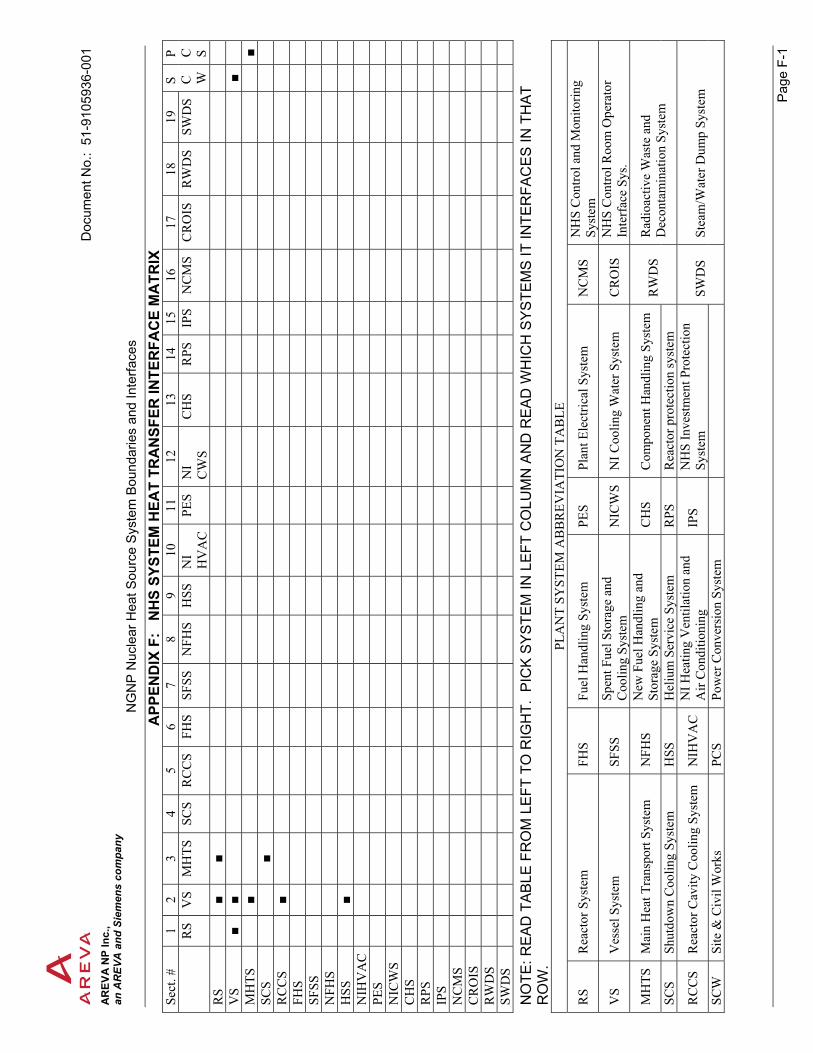
D
ocum
ent N
o.:
51-9
1059
36-0
01
AR
EVA
NP
Inc.
, an
AR
EVA
and
Sie
men
s co
mpa
nyN
GN
P N
ucle
ar H
eat S
ourc
e S
yste
m B
ound
arie
s an
d In
terfa
ces
P
age
F-1
APP
END
IX F
: N
HS
SYST
EM H
EAT
TRA
NSF
ER IN
TER
FAC
E M
ATR
IX
Sect
. #
1 2
3 4
5 6
7 8
9 10
11
12
13
14
15
16
17
18
19
RS
VS
MH
TS
SCS
RC
CS
FHS
SFSS
N
FHS
HSS
N
I H
VA
C
PES
NI
CW
S C
HS
RPS
IP
S N
CM
S C
RO
IS
RW
DS
SWD
S S C
W
P C
S R
S
� �
VS
� �
�
M
HTS
�
�
SCS
�
R
CC
S
�
FHS
SF
SS
N
FHS
H
SS
�
N
IHV
AC
PES
NIC
WS
C
HS
R
PS
IP
S
N
CM
S
C
RO
IS
R
WD
S
SWD
S
NO
TE: R
EA
D T
AB
LE F
RO
M L
EFT
TO
RIG
HT.
PIC
K S
YS
TEM
IN L
EFT
CO
LUM
N A
ND
RE
AD
WH
ICH
SY
STE
MS
IT IN
TER
FAC
ES
IN T
HA
T R
OW
. PL
AN
T SY
STEM
AB
BR
EVIA
TIO
N T
AB
LE
RS
Rea
ctor
Sys
tem
FH
S Fu
el H
andl
ing
Syst
em
PES
Plan
t Ele
ctric
al S
yste
m
NC
MS
NH
S C
ontro
l and
Mon
itorin
g Sy
stem
VS
Ves
sel S
yste
m
SFSS
Sp
ent F
uel S
tora
ge a
nd
Coo
ling
Syst
em
NIC
WS
NI C
oolin
g W
ater
Sys
tem
C
RO
IS
NH
S C
ontro
l Roo
m O
pera
tor
Inte
rfac
e Sy
s.
MH
TS
Mai
n H
eat T
rans
port
Syst
em
NFH
S N
ew F
uel H
andl
ing
and
Stor
age
Syst
em
CH
S C
ompo
nent
Han
dlin
g Sy
stem
SCS
Shut
dow
n C
oolin
g Sy
stem
H
SS
Hel
ium
Ser
vice
Sys
tem
R
PS
Rea
ctor
pro
tect
ion
syst
em
RW
DS
Rad
ioac
tive
Was
te a
nd
Dec
onta
min
atio
n Sy
stem
RC
CS
Rea
ctor
Cav
ity C
oolin
g Sy
stem
N
IHV
AC
N
I Hea
ting
Ven
tilat
ion
and
Air
Con
ditio
ning
IP
S N
HS
Inve
stm
ent P
rote
ctio
n Sy
stem
SC
W
Site
& C
ivil
Wor
ks
PCS
Pow
er C
onve
rsio
n Sy
stem
SW
DS
Stea
m/W
ater
Dum
p Sy
stem