employment of eulerian, lagrangian, and arbitrary
TRANSCRIPT
EMPLOYMENT OF EULERIAN, LAGRANGIAN, AND ARBITRARY
LAGRANGIAN-EULERIAN DESCRIPTION FOR CRACK OPENING
PROBLEM E.A. Ivanova1,2, D.V. Matyas1*, M.D. Stepanov1
1Higher School of Theoretical Mechanics, Peter the Great St. Petersburg Polytechnic University,
Polytechnicheskaya 29, St. Petersburg, Russia 2Laboratory of Mechatronics, Institute for Problems in Mechanical Engineering of Russian Academy of Sciences
(IPME RUS), Bolshoy pr. V.O. 61, St.-Petersburg, Russia
*e-mail: [email protected]
Abstract. Numerical study of crack opening in the solid material of rock formation is presented in this article. Initially introduced straight-line crack is widened by increasing internal pressure. The crack shape evolution resembles hydraulic fracturing and is considered as a transient process. Commercial code LS-DYNA was employed to obtain solutions by three types of descriptions, they are compared to the solution obtained in Eulerian description by a program based on the finite-volume method and written in Python language. The main features of the self-developed code are a direct relation between velocities and strains, and a deriving of the aperture through density distribution. Keywords: solid mechanics, finite-volume method, numerical simulations, Eulerian description, Lagrangian description, arbitrary Lagrangian-Eulerian description, crack opening, hydraulic fracturing 1. Introduction A variety of formulations exists in the problem of crack opening, the main concepts and approaches to solution of problem are presented in the following papers [1-4]. In the present article the focus is on numerical two-dimensional modeling of a crack opening by means of different descriptions. It is well-known that two approaches are used to describe the kinematics of continuum medium – Lagrangian description [5-8] and Eulerian description [9-11]. Generally, the Lagrangian description is utilized for solid dynamic deformation calculations. But a significant limitation on the applicability of the Lagrangian description is imposed by the hypothesis of local topology. The key issue of the hypothesis is the requirement that closely located material particles shall remain closely located during any movement. Obviously, this condition is not fulfilled in the case of liquids and loose media which behave like liquids. Furthermore in some cases, for instance when a plastic flow or discontinuities caused by micro-cracks occur within the solid medium, the correct application of a Lagrangian description may become difficult.
The Eulerian description was developed and used during the last two centuries mostly in the dynamics of gas and fluid [9,11-13]. As well the Eulerian description is widely employed in simulation of slurry multicomponent flow and sedimentation where a granular medium is considered, but fewer works deal with modeling of deformable solid [14-21]. Moreover, recently this approach was extensively enhanced and began to be used for simulation of
Materials Physics and Mechanics 42 (2019) 470-483 Received: July 31, 2019
http://dx.doi.org/10.18720/MPM.4242019_12 © 2019, Peter the Great St. Petersburg Polytechnic University © 2019, Institute of Problems of Mechanical Engineering RAS
medium with rotational degree of freedom [22-29]. In the case of the Lagrangian description, the finite element method is employed that
requires low ratio between finite elements mesh dimensions for convergence and accuracy. In the case of Eulerian description, the finite volume method is utilized that allows using a mesh with significantly different characteristic dimensions in the same element which is helpful in case of hydraulic fracturing simulation where length and height of crack reach tens of meters while aperture does not exceed a few millimeters [30,31]. For this simulation the mesh size in direction of crack widening should be accordingly equal to an order of millimeters. Choosing the mesh with the same characteristic dimensions in two other directions leads to immense computational costs. However, from a physical point of view, it seems reasonable to use a rather coarse mesh in the direction of the length and height of the crack. Therefore, applying a Eulerian description for this problem is interesting not only from a theoretical point of view but also has great practical importance. From another side, since the implication of the Lagrangian description is also quite suitable for this kind of simulation, it could be considered as a benchmark problem and serve as an example and base for a comparative analysis of the numerical results obtained by different methods.
We note that the application of Eulerian description in deformable solid dynamics has specific features comparing with employment in fluid dynamics. These distinctions are evoked due to the presence of deviatoric part of elastic stress tensor and consequently due to necessity in introducing of the strain tensor as a variable. More details see in works [27,32,33].
Reviewing commercial software, it was established that the Lagrangian description is currently implemented in a large number of engineering software systems. At the same time, the Eulerian description is not so widely applied for modeling of processes in a solid body. For example, commercial software FLUENT, which is a part of ANSYS, allows only thermal simulations in a solid medium. It turned out that the engineering programs ABAQUS and LS-DYNA have the widest possibilities for calculations based on Eulerian description. Both of them also have arbitrary Lagrangian-Eulerian solver that is most conveniently implemented within the framework of the LS-DYNA software package. Thus, in order to unify the process of creating computational models, the LS-DYNA program was chosen as a commercial software package for the numerical solution of the problem. This commercial software specializes in solving highly-nonlinear problems by finite element method with the use of an explicit time integration scheme.
Self-written program on Python partly coincides with general finite-volume numerical schemes used in hydrodynamics. As in computational hydrodynamics, the mass and momentum balance equations in the integral form are utilized as the main equations. But in case of deformable solid seven scalar values are used as the main unknown variables, three of which are specified in the centers of elementary cells (density and two projections of velocity), two – on the vertical sides (xx and yx components of deformation tensor) and two – on the horizontal sides of cell (xy and yy components of deformation tensor). Mass and momentum flow in the balance equations are determined on the basis of the velocity direction analysis. As well if the velocity in the given elementary cell is directed to the right, the values of deformations on the left side of this cell are used, and vice versa. Similar to hydrodynamics scheme, this numerical scheme allows calculations with the use of a highly uneven mesh in space. Key features distinguishing the program from LS-DYNA code such as nonlinear constitutive equations, are discussed in section 2.
2. Problem formulation The dynamic process of crack opening caused by the influence of the internal monotonically increasing pressure applied to the crack edge is studied. It is presumed that the original crack profile is flat and located in a vertical plane. The case of plain strain was reviewed. In other
Employment of Eulerian, Lagrangian, and arbitrary Lagrangian-Eulerian description for crack opening problem 471

words, the cross-section perpendicular to the crack length was considered, and the crack length was assumed to be infinite. The material is presumed to be initially in the undeformed state. The crack is a slice where the stresses can only be compressive or zero. In order to simplify the problem, it is supposed that further growth of the crack associated with the failure of the material is impossible.
Ideally elastic model of material is implemented for the rock layer, no viscosity or other velocity-related properties such as dissipation are implemented in the material model.
Deformable solid dynamics problem is summarized in the following equations system: − mass balance
δρδ𝑡𝑡
+ ρ ∇ ⋅ 𝒗𝒗 = 0, (1) where δ/δt is material derivative, ρ is density, v is velocity vector;
− momentum balance ∇ ⋅ 𝛕𝛕 + ρ𝒇𝒇 = ρ δ𝒗𝒗
δ𝑡𝑡, 𝛕𝛕T = 𝛕𝛕, (2)
where τ is stress tensor, f is external force per unit of mass; − velocity and strain definition
𝒗𝒗 = δ𝒖𝒖δ𝑡𝑡
, 𝛆𝛆 = ∇𝒖𝒖 + 𝒖𝒖∇2
, (3) where u is dispacement vector, ε is strain tensor;
− constitutive equation 𝛕𝛕 = 2µ𝛆𝛆 + λ𝑬𝑬tr(𝛆𝛆), (4) where λ and µ are Lame parameters, tr denotes tensor trace, and E is identity tensor.
The calculation domain is chosen large enough so that the conditions at its external boundary do not have a noticeable impact on the processes causing the widening of a crack.
Main ideas of descriptions implemented for the crack opening problem. Deformable solid problem is more convenient to consider in Lagrangian description framework, where it is easier to formulate boundary conditions and apply loads. In this framework boundary movements do not complicate load imposition, and only domain containing material is calculated. If deformations are substantially large, the arbitrary Lagrangian-Eulerian description could be implemented to obtain reliable results. However, the pure Eulerian description, which is commonly utilized in fluid dynamics, could be as well useful in deformable solid problem. For instance, in hydraulic fracturing problem, where several components (including fluid and deformable solid) are interacting, the implication of Lagrangian framework seems to be more practical. Instead of additional equations prescribed at numerous contact surfaces in case of Lagrangian description, only volumetric forces could be introduced in Eulerian description. This replacement greatly decreases computational cost. Besides that, viscous interaction forces, as well as elastic ones, could be included in the simulation. Porous deformable solid is feasible to model through Eulerian description whereas in Lagrangian description penetration of fluid into solid could not be explicitly considered. One more advantage of Eulerian description is a freer choice of cells aspect ratio. Finite-volume method imposes much fewer requirements to that aspect ratio than the finite-elements method, this fact is important in the problem of a crack opening where aperture width is a several order less than the crack height. But in order to proceed towards multi-component formulation, the Eulerian description approach should be justified and thoroughly checked against solution obtained by other approaches in case of one component.
In case of Eulerian description the boundary of the calculation domain consists only of the external boundary Γext. Empty space inside the crack belongs to the calculation domain. The position of the crack walls is determined through analysis of material density jump. The external influence leading to crack opening is modeled by the equivalent volume force ρf in the equation of motion (2). In the continuum formulation of the problem this force is related to the
472 E.A. Ivanova, D.V. Matyas, M.D. Stepanov
pressure p with the equation ρ𝒇𝒇 = −𝑝𝑝δ(ξ − 0)𝒏𝒏, (5) where δ(ξ – 0) is Dirac delta-function, ξ is coordinate directed along the normal to the crack wall, i.e. in the direction of a single vector n, with ξ = 0 on the crack wall.
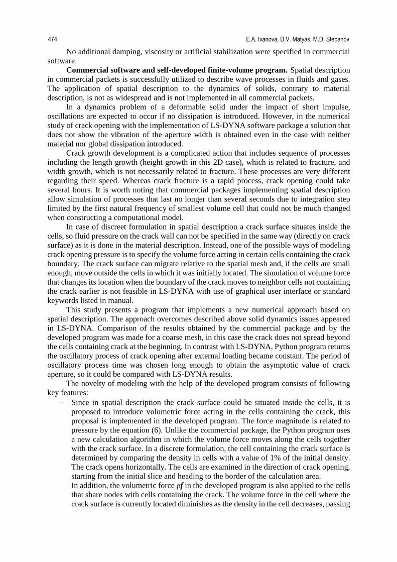
This force is given in the cells adjoining to a slice, and as cells are emptied, force is transferred to the next cells. Taking into account the ratio of the crack height and its maximum opening, and the corresponding choice of cells sizes, it is assumed that the force simulating pressure is directed along the axis x in all cells as shown in Fig. 1. The volumetric force module ρf is evaluated from the pressure value p through the relation |ρ𝒇𝒇| = 𝑝𝑝/ℎ𝑥𝑥, (6) where hx is the horizontal size of considering cell.
In case of Lagrangian and arbitrary Eulerian-Lagrangian description the boundary of computing domain consists of external boundary Γext and crack walls Γcrack. The pressure p, which opens the crack, has the role of a boundary condition that is formulated as 𝒏𝒏 ⋅ 𝝉𝝉|Γ𝑐𝑐𝑐𝑐𝑐𝑐𝑐𝑐𝑐𝑐 = −𝑝𝑝𝒏𝒏, (7) where n is a unit external normal vector to the crack boundary.
Simulation parameters. The crack height was chosen to be one-third of formation height (see Fig. 1). Pressure p, which acts on the edges of the crack, linearly increases and reaches maximum value 5 MPa at time point 1 second, further in time pressure remains unchanged until the end of the calculation.
Following parameters are used for the formation material model: − density value equals to 2500 kg/m3; − bulk modulus value equals to 18 GPa; − Poisson’s coefficient is equal to 0,3.
Fig. 1. Geometry of domain and mesh pattern
The computational models for all three methods of solid description were prepared in
commercial software LS-DYNA. In order to reduce computational time, symmetry has been taken into account. Uneven mesh in x-direction was used, in one case cells horizontal size varies from 20 mm to 100 meters, in another case more refined mesh that begins from several cells with one-millimeter horizontal edge was utilized. In y-direction mesh consists of 21 cells with uniform size. In order to obtain proper comparision same spatial mesh as in LS-DYNA was utilised in program writen on Python.
250 m
120 m
Employment of Eulerian, Lagrangian, and arbitrary Lagrangian-Eulerian description for crack opening problem 473
No additional damping, viscosity or artificial stabilization were specified in commercial software.
Commercial software and self-developed finite-volume program. Spatial description in commercial packets is successfully utilized to describe wave processes in fluids and gases. The application of spatial description to the dynamics of solids, contrary to material description, is not as widespread and is not implemented in all commercial packets.
In a dynamics problem of a deformable solid under the impact of short impulse, oscillations are expected to occur if no dissipation is introduced. However, in the numerical study of crack opening with the implementation of LS-DYNA software package a solution that does not show the vibration of the aperture width is obtained even in the case with neither material nor global dissipation introduced.
Сrack growth development is a complicated action that includes sequence of processes including the length growth (height growth in this 2D case), which is related to fracture, and width growth, which is not necessarily related to fracture. These processes are very different regarding their speed. Whereas crack fracture is a rapid process, crack opening could take several hours. It is worth noting that commercial packages implementing spatial description allow simulation of processes that last no longer than several seconds due to integration step limited by the first natural frequency of smallest volume cell that could not be much changed when constructing a computational model.
In case of discreet formulation in spatial description a crack surface situates inside the cells, so fluid pressure on the crack wall can not be specified in the same way (directly on crack surface) as it is done in the material description. Instead, one of the possible ways of modeling crack opening pressure is to specify the volume force acting in certain cells containing the crack boundary. The crack surface can migrate relative to the spatial mesh and, if the cells are small enough, move outside the cells in which it was initially located. The simulation of volume force that changes its location when the boundary of the crack moves to neighbor cells not containing the crack earlier is not feasible in LS-DYNA with use of graphical user interface or standard keywords listed in manual.
This study presents a program that implements a new numerical approach based on spatial description. The approach overcomes described above solid dynamics issues appeared in LS-DYNA. Comparison of the results obtained by the commercial package and by the developed program was made for a coarse mesh, in this case the crack does not spread beyond the cells containing crack at the beginning. In contrast with LS-DYNA, Python program returns the oscillatory process of crack opening after external loading became constant. The period of oscillatory process time was chosen long enough to obtain the asymptotic value of crack aperture, so it could be compared with LS-DYNA results.
The novelty of modeling with the help of the developed program consists of following key features:
− Since in spatial description the crack surface could be situated inside the cells, it is proposed to introduce volumetric force acting in the cells containing the crack, this proposal is implemented in the developed program. The force magnitude is related to pressure by the equation (6). Unlike the commercial package, the Python program uses a new calculation algorithm in which the volume force moves along the cells together with the crack surface. In a discrete formulation, the cell containing the crack surface is determined by comparing the density in cells with a value of 1% of the initial density. The crack opens horizontally. The cells are examined in the direction of crack opening, starting from the initial slice and heading to the border of the calculation area. In addition, the volumetric force ρf in the developed program is also applied to the cells that share nodes with cells containing the crack. The volume force in the cell where the crack surface is currently located diminishes as the density in the cell decreases, passing
474 E.A. Ivanova, D.V. Matyas, M.D. Stepanov

to the neighboring cell. Ratios of values of volume force in the considered cell and in the following one are determined by the ratio of densities in these two cells as follows (formulas are given for the case of positive horizontal component of velocity in considered cells): 𝑓𝑓𝑖𝑖 = 𝑝𝑝
ℎ𝑥𝑥𝑖𝑖 ρ𝑖𝑖+1
, 𝑓𝑓𝑖𝑖+1 = 𝑝𝑝 ℎ𝑥𝑥
𝑖𝑖+1 𝜌𝜌𝑖𝑖+1−𝜌𝜌𝑖𝑖
�𝜌𝜌𝑖𝑖+1�2 , (8)
where the upper index indicates the horizontal number of the cell. Sharing of the volume force between i and i+1 cells allows smooth redistribution of the volume force that helps to avoid numerical difficulties when crack surface moves from i cell to i+1 cell.
− In fluid dynamics, the system of equations describing continua motion contains two momentum and mass balance equations, which are partial differential equations, and one algebraic equation of state that relates pressure and density. In the case of a deformable solid, shear stiffness makes the density and pressure relationship inapplicable; instead, the constitutive relationship between stress and strain is defined. In the material description, strains are defined through displacements gradient. In the spatial description, one could formally follow this logic and calculate the gradient of the displacements obtained from velocity field utilizing following differential equation: 𝛿𝛿𝒖𝒖(𝒓𝒓, 𝑡𝑡)
𝛿𝛿𝑡𝑡= 𝐕𝐕(𝒓𝒓, 𝑡𝑡). (9)
However, this does not reveal the physical meaning of displacements in the spatial description. It is difficult to comprehend the physical meaning of displacements, and thus it is complicated to assign the boundary conditions for them. Instead, this paper proposes a new numerical approach employing introduced deformations g that are calculated directly from the velocity field with the help of following differential equation: 𝛿𝛿𝐠𝐠𝛿𝛿𝑡𝑡
= −(∇𝐕𝐕) ∙ 𝐠𝐠. (10)
The internal energy can be expressed through the tensor g and its invariants, therefore it is possible to obtain an algebraic expression that bonds g with the stress tensor and completes the system of equations. Thus, due to the absence of displacements as the main variables, there is no need to assign the boundary conditions for them.
− As shown above displacements can be formally calculated in cells containing the crack. Component of displacement ux is not equivalent to the crack aperture because the initial position defined by formula (9) of the material particles located currently at the crack surface does not coincide with the position of the crack surface at the initial moment of calculation. Thus the issue arises how to determine the crack aperture in the spatial description. In case of a fine spatial grid, the crack aperture can be tracked approximately by the number of empty cells. For a more accurate assessment of crack aperture, which is particularly relevant for a coarse mesh and fast calculations, a new approach of determining crack aperture is proposed. It is based on the analysis of the density distribution in the calculation domain. In order to determine the exact crack aperture, the following formula is used. First addend represents the width of empty cells, the second addend accounts for the position of the crack wall within the cell containing it:
𝑎𝑎(𝑡𝑡) = � ℎ𝑥𝑥𝑖𝑖
𝑚𝑚
𝑖𝑖=1
+ ℎ𝑥𝑥𝑖𝑖+1 �1 −
ρ𝑖𝑖+1
ρmax𝑖𝑖+1 �, (11)
where m is empty cells number in considered horizontal row, ρmax is the maximum recorded at previous steps density in the cell currently containing crack wall.
Employment of Eulerian, Lagrangian, and arbitrary Lagrangian-Eulerian description for crack opening problem 475
− Next, the issue of relations between stresses and deformations in spatial description is surveyed. For convenience, the volume strain I3(g) = Det g and shear strain expressed as an auxiliary strain measure Λ = I3-2/3(g) g·gT are introduced. Scalar invariants of the strain measure are defined as I1 = tr Λ, I2 = Λ·· Λ. If spatial description is used, material may obviously completely leave some cells of calculation domain, this process corresponds to large deformations. The absence of density in these volumes, what is equivalent to I3(g) = 0, means that there are zero stresses τ in them. Therefore, for an ideally elastic solid in the developed program nonlinear equations linking stresses and strains are proposed:
𝛕𝛕 = −𝐴𝐴1𝐼𝐼3
83(𝐼𝐼1𝑬𝑬 + 2𝚲𝚲) − 𝐴𝐴1𝐼𝐼3
103 (𝐼𝐼2𝑬𝑬 + 4𝚲𝚲𝟐𝟐) − 𝐴𝐴3𝐼𝐼3
2𝑬𝑬, (12)
where constants A1, A2, A3 expresses through bulk modulus K and shear modulus G as:
𝐴𝐴1 =6K − 7G
6, 𝐴𝐴2 =
5K − 3G12
, 𝐴𝐴3 =35G − 39K
12. (13)
As the density simultaneously with I3(g ) tends to zero, all components of the stress tensor τ vanish. Constants A1, A2, A3 are selected in such manner that at small deformations equation (12) asymptotically tends to the well-known relations of the linear theory of elasticity. It should be emphasized that this nonlinearity is not associated with the physical characteristics of the material but with the specificity of the Eulerian description.
The implicit integration scheme was programmed in Python, and the "newton_krylov" package from the "scipy.optimize" library was used to solve the system of nonlinear algebraic equations. To facilitate convergence, speed, and accuracy, dimensionless variables and parameters were introduced in the program.
Note that in the case of Eulerian description it is possible to consider half of the domain due to symmetry of the problem. However, it is interesting not only to solve a particular problem but to develop a general approach that could be easily extended to the case of a large number of cracks distributed arbitrarily throughout the entire volume of the domain. Therefore, despite the symmetry of the problem, the whole calculation domain is included in the simulations by self-developed code. 3. Results and discussion
Comparison. The main idea of this study is to verify that different approaches in LS-DYNA give coincided results and, basing on this verification, to compare Python and LS-DYNA results found employing Eulerian description. Since the main variables in Python code are density, velocities, and strains but not displacements, comparison of apertures sizes seems to be most suitable. Besides that, the stress distributions, which could be important if the case of material fracture was considered, are compared as another way to prove resemblance of solutions. But firstly displacement and density distributions are presented to depict the general disposition of deformation.
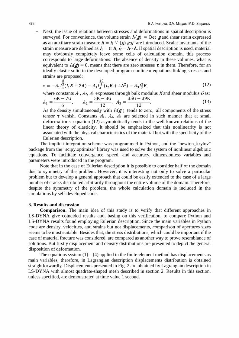
The equations system (1) – (4) applied in the finite-element method has displacements as main variables, therefore, in Lagrangian description displacements distribution is obtained straightforwardly. Displacements presented in Fig. 2 are obtained by Lagrangian description in LS-DYNA with almost quadrate-shaped mesh described in section 2. Results in this section, unless specified, are demonstrated at time value 1 second.
476 E.A. Ivanova, D.V. Matyas, M.D. Stepanov
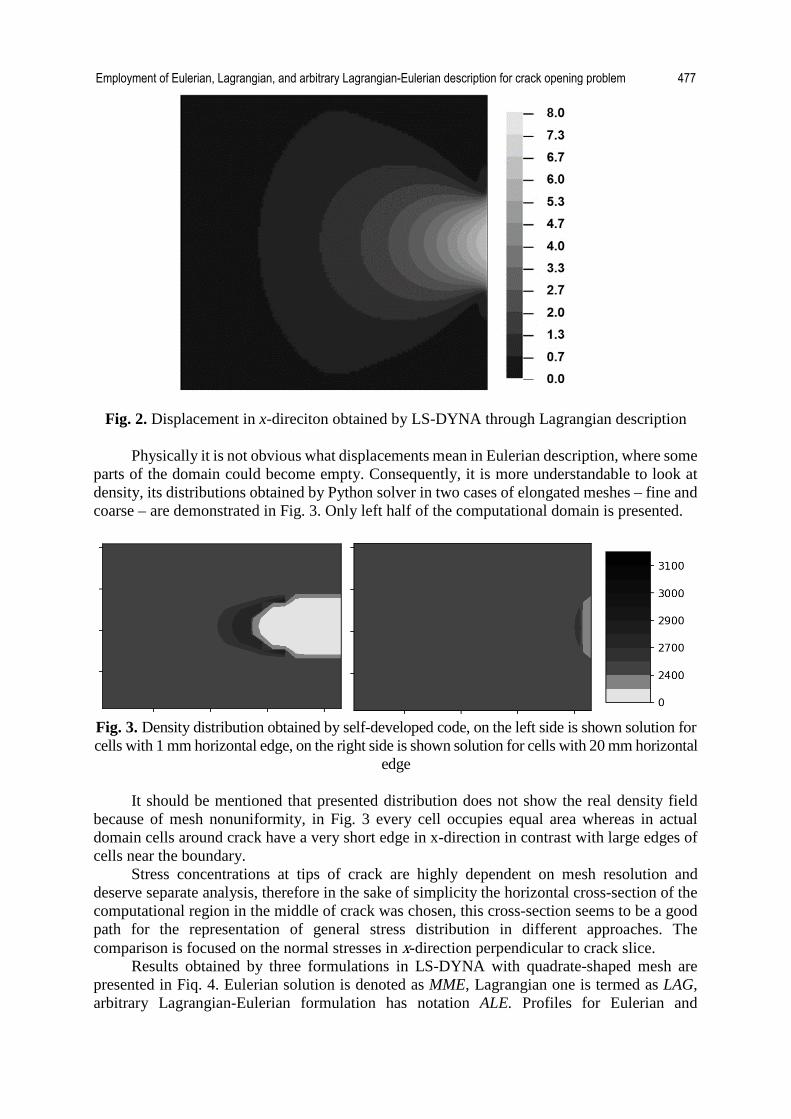
Fig. 2. Displacement in x-direciton obtained by LS-DYNA through Lagrangian description
Physically it is not obvious what displacements mean in Eulerian description, where some parts of the domain could become empty. Consequently, it is more understandable to look at density, its distributions obtained by Python solver in two cases of elongated meshes – fine and coarse – are demonstrated in Fig. 3. Only left half of the computational domain is presented.
Fig. 3. Density distribution obtained by self-developed code, on the left side is shown solution for cells with 1 mm horizontal edge, on the right side is shown solution for cells with 20 mm horizontal
edge
It should be mentioned that presented distribution does not show the real density field because of mesh nonuniformity, in Fig. 3 every cell occupies equal area whereas in actual domain cells around crack have a very short edge in x-direction in contrast with large edges of cells near the boundary.
Stress concentrations at tips of crack are highly dependent on mesh resolution and deserve separate analysis, therefore in the sake of simplicity the horizontal cross-section of the computational region in the middle of crack was chosen, this cross-section seems to be a good path for the representation of general stress distribution in different approaches. The comparison is focused on the normal stresses in x-direction perpendicular to crack slice.
Results obtained by three formulations in LS-DYNA with quadrate-shaped mesh are presented in Fiq. 4. Eulerian solution is denoted as MME, Lagrangian one is termed as LAG, arbitrary Lagrangian-Eulerian formulation has notation ALE. Profiles for Eulerian and
Employment of Eulerian, Lagrangian, and arbitrary Lagrangian-Eulerian description for crack opening problem 477
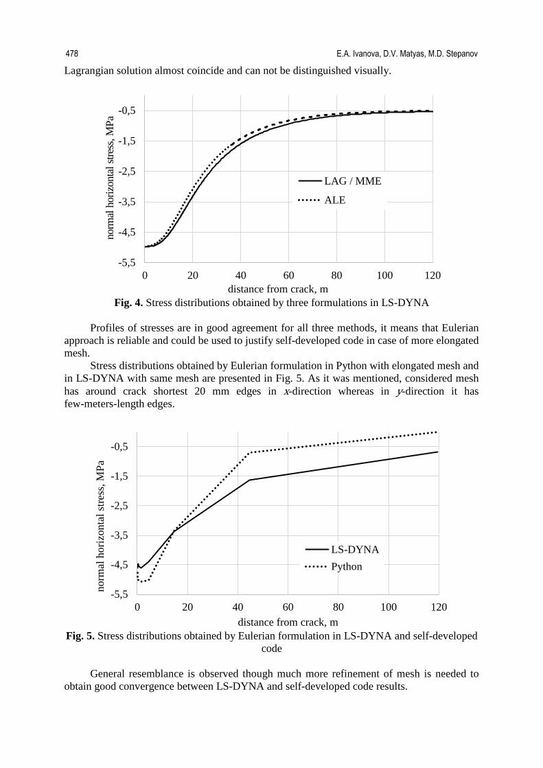
Lagrangian solution almost coincide and can not be distinguished visually.
Fig. 4. Stress distributions obtained by three formulations in LS-DYNA
Profiles of stresses are in good agreement for all three methods, it means that Eulerian
approach is reliable and could be used to justify self-developed code in case of more elongated mesh.
Stress distributions obtained by Eulerian formulation in Python with elongated mesh and in LS-DYNA with same mesh are presented in Fig. 5. As it was mentioned, considered mesh has around crack shortest 20 mm edges in x-direction whereas in y-direction it has few-meters-length edges.
Fig. 5. Stress distributions obtained by Eulerian formulation in LS-DYNA and self-developed
code
General resemblance is observed though much more refinement of mesh is needed to obtain good convergence between LS-DYNA and self-developed code results.
-5,5
-4,5
-3,5
-2,5
-1,5
-0,5
0 20 40 60 80 100 120
norm
al h
oriz
onta
l stre
ss, M
Pa
distance from crack, m
LAG / MME
ALE
-5,5
-4,5
-3,5
-2,5
-1,5
-0,5
0 20 40 60 80 100 120
norm
al h
oriz
onta
l stre
ss, M
Pa
distance from crack, m
LS-DYNAPython
478 E.A. Ivanova, D.V. Matyas, M.D. Stepanov
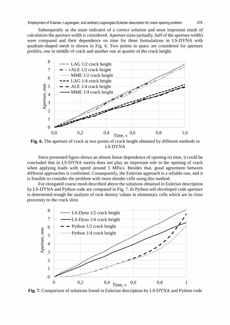
Subsequently as the main indicator of a correct solution and most important result of calculation the aperture width is considered. Aperture sizes (actually, half of the aperture width) were compared and their dependence on time for three formulations in LS-DYNA with quadrate-shaped mesh is shown in Fig. 6. Two points in space are considered for aperture profiles, one in middle of crack and another one at quarter of the crack height.
Fig. 6. The aperture of crack at two points of crack height obtained by different methods in
LS-DYNA
Since presented figure shows an almost linear dependence of opening on time, it could be concluded that in LS-DYNA inertia does not play an important role in the opening of crack when applying loads with speed around 5 MPa/s. Besides that, good agreement between different approaches is confirmed. Consequently, the Eulerian approach is a reliable one, and it is feasible to consider the problem with more slender cells using this method.
For elongated coarse mesh described above the solutions obtained in Eulerian description by LS-DYNA and Python code are compared in Fig. 7. In Python self-developed code aperture is determined trough the analysis of rock density values in elementary cells which are in close proximity to the crack slice.
Fig. 7. Comparison of solutions found in Eulerian description by LS-DYNA and Python code
0
1
2
3
4
5
6
7
8
0,0 0,2 0,4 0,6 0,8 1,0
Ape
rture
, mm
Time, s
LAG 1/2 crack heightALE 1/2 crack heightMME 1/2 crack heightLAG 1/4 crack heightALE 1/4 crack heightMME 1/4 crack height
0
1
2
3
4
5
6
7
8
0 0,2 0,4 0,6 0,8 1
Ape
rture
, mm
Time, s
LS-Dyna 1/2 crack heightLS-Dyna 1/4 crack heightPython 1/2 crack heightPython 1/4 crack height
Employment of Eulerian, Lagrangian, and arbitrary Lagrangian-Eulerian description for crack opening problem 479

Despite the final values are in some agreement, a self-developed code solution shows significant nonlinearity, and it could be presumed that further behavior of aperture size would not converge in a short time.
As a next step, the mesh convergence of Python code is studied, solution on refined mesh starting with 1 mm along x-direction is compared to the previous solution on mesh with 20 mm cells. Comparison is presented in Fig. 8.
Fig. 8. Mesh convergence for self-developed code
The shorter horizontal edges are chosen and the more slender mesh is studied, the higher
pace of crack opening is observed. Note that in case of mesh starting from 1 mm along x-direction several cells became empty.
To find the behavior of solution after the load has been fixed at maximum value, which happens at 1 second time point, the solutions by LS-DYNA and Python code with coarse elongated mesh for time range 5 seconds were calculated. Aperture size is shown in Fig. 9. One point in space is considered in the middle of crack height. Previously considered material in Python self-developed code does not possess any viscosity, an additional profile was found in case of material for which this property inheres.
Estimated aperture, to which Python profiles asymptotically tends, is slightly larger than aperture obtained by LS-DYNA.
Fig. 9. Aperture size for time range 5 seconds, the external load has been fixed at time value
1 second
0
1
2
3
4
5
6
7
8
0 0,2 0,4 0,6 0,8 1
Ape
rture
, mm
Time, s
1 mm 1/4 crack height
1 mm 1/2 crack height
20 mm 1/2 crack height
20 mm 1/4 crack height
0
2
4
6
8
10
12
14
0 1 2 3 4 5
Ape
rture
, mm
Time, s
LS-DYNAPython with viscosityPython without viscosity
480 E.A. Ivanova, D.V. Matyas, M.D. Stepanov
Conclusions. The presented analysis shows that stresses and aperture width obtained by different approaches in LS-DYNA do coincide accurately enough to rely on Eulerian approach and consider it as the base in the comparison between LS-DYNA and self-developed code. From one side, carried calculations have confirmed that the solution obtained by Eulerian approach demands more computing resources and time for a similar mesh. From other side, in such problems like crack opening it is necessary to have small mesh size in direction perpendicular to crack, model prepared for Lagrangian description should have cells dimension in parallel to crack direction with the same order as dimension in perpendicular to crack direction, but model prepared for Eulerian description could have elongated cells with a large ratio between parallel to crack and perpendicular to crack sizes that is more convenient and saves computational time.
The novelty of numerical approach based on spatial description and implemented in self-developed Python program is expressed by followings:
− In order to model pressure opening the crack, it is proposed to introduce in numerical algorithm the volumetric force acting in the cells containing the crack. Besides that, the volume force moves along the cells together with the crack surface and is partly applied to the cells which neighbors contains the crack. This force assignment is included in the algorithm in order to avoid numerical difficulties during a transfer of crack wall from one cell to another and for smooth redistribution of volume force.
− Since it is difficult to comprehend the physical meaning of displacements in spatial description, it is preferably to avoid assignment of boundary conditions for them. In order to do that, for the first time in numerical algorithm differential equations linking directly velocity vector projections and strain tensor components are employed. This approach allows displacements to be excluded from consideration.
− The new method has been proposed to accurately assess crack aperture. The ratio of the current density to the maximum recorded density in a given cell for the whole time of calculation is multiplied by the width of the cell in the horizontal direction to obtain the position of the crack surface inside the cell. Together with the width of the empty cells, the crack wall position inside the current cell shows the crack opening.
− The absence of material in the cells should correspond to zero stresses, so for implementation in the Python program new nonlinear equations that connect stresses with deformations are suggested. The introduced relations asymptotically tend to the well-known equations of linear elasticity theory at small deformations.
In summary, normal stresses and aperture size obtained by Eulerian description in LS-DYNA and Python do not coincide accurately, however, the general resemblance is notable. The main distinction is the nonlinear dependence between load and crack opening in case of Python code whereas in LS-DYNA’s results the dependence is almost linear. In contrast with LS-DYNA results, self-developed Python program correctly simulates the transfer of the external forces to kinetic energy and returns results where oscillations of crack aperture size are observed after load becomes constant in time. Crack opening converges toward static value the faster the more dissipation or viscosity are introduced in self-developed numerical scheme. The asymptotic value of aperture obtained by Python program and the value found by LS-Dyna code coincide accurately enough.
Also by performing calculations, it was established that the elapsed time spent by developed program is several times less than the runtime needed in commercial package.
Future development and challenges. For lower rate of the applied load change the dynamic terms in momentum balance would have an insignificant impact on the process. It is obvious that the solution of the problem in the quasi-static formulation allows the simulations of any large duration processes. If the right side in equation (2) is omitted, which means the absence of dynamic terms, the time spent on calculation would not depend on the duration of
Employment of Eulerian, Lagrangian, and arbitrary Lagrangian-Eulerian description for crack opening problem 481
the process. The developed program allows simulation of the quasi-static process without limitation on its duration. This simulation is planned for future investigation of self-developed Python code.
As a future self-developed program extension the porous model could be implemented in solid material. This would allow introduction of viscous forces between solid and fluid continua that prevent unresistant fluid flow away from crack after initial penetration into solid happens. As well porous model implies the presence of pore pressure in a solid medium that helps to predict crack opening more accurately.
Besides that one more aim of investigation could be construction in Python code of a multi-component model where proppant and oil alongside with fracking fluid and rock would be analyzed. Another interesting topic would be to study stress distribution around crack tips to predict whether crack extends. Acknowledgments. This work was supported by Ministry of Science and Higher Education of the Russian Federation within the framework of the Federal Program "Research and development in priority areas for the development of the scientific and technological complex of Russia for 2014 – 2020" (activity 1.2), grant No. 14.575.21.0146 of September 26, 2017, unique identifier: RFMEFI57517X0146. The industrial partner of the grant is LLC "Gazpromneft Science & Technology Centre". References [1] Hoek E, Martin CD. Fracture initiation and propagation in intact rock–a review. Journal of Rock Mechanics and Geotechnical Engineering. 2014;6(4): 287-300. [2] Zhong XC, Xian-Fang L. Magnetoelectroelastic analysis for an opening crack in a piezoelectromagnetic solid. European Journal of Mechanics-A/Solids. 2007;26(3): 405-417. [3] Sneddon IN, Elliot HA. The opening of a Griffith crack under internal pressure. Quarterly of Applied Mathematics. 1946;4(3): 262-267. [4] Freund LB. Crack propagation in an elastic solid subjected to general loading–I. Constant rate of extension. Journal of the Mechanics and Physics of Solids. 1972;20(3): 129-140. [5] Eringen C. Mechanics of Continua. NY: Robert E. Krieger Publishing Company; 1980. [6] Wilmanski K. Thermomechanics of continua. Berlin: Springer; 1998. [7] Malvern E. Introduction to the Mechanics of a Continuous Medium. New Jersey: Prentice-Hall, Inc.; 1969. [8] Truesdell C. A First Course in Rational Continuum Mechanics. Baltimore, Maryland: The Johns Hopkins University; 1972. [9] Batchelor G. An Introduction to Fluid Dynamics. Cambridge: Cambridge University Press; 1970. [10] Loicyanskii LG. Mekhanika Zhidkosti i Gaza (Mechanics of Fluids, in Russ.). Moscow: Nauka; 1987. [11] Daily J, Harleman D. Fluid Dynamics. Massachusetts: Addison–Wesley; 1966. [12] Birkhoff G. Hydrodynamics. A study in logic, fact and similitude. New Jersey: Princeton University Press; 1960. [13] Prandtl L, Tietjens O. Hydro- und Aeromechanik. Berlin: Springer; 1929. [14] Valkov B, Rycroft CH, Kamrin K. Eulerian Method for Multiphase Interactions of Soft Solid Bodies in Fluids. Journal of Applied Mechanics. 2015;82(4): 041011. [15] Kamrin K, H Rycroft C, Nave JC. Reference map technique for finite-strain elasticity and fluid-solid interaction. Journal of the Mechanics and Physics of Solids. 2012;60(11): 1952-1969.
482 E.A. Ivanova, D.V. Matyas, M.D. Stepanov
[16] Ortega AL, Lombardini M, Pullin DI, Meiron DI. Numerical simulation of elastic-plastic solid mechanics using an Eulerian stretch tensor approach and HLLD Riemann solver. Journal of Computational Physics. 2014;257: 414-441. [17] Colella P. A conservative three-dimensional Eulerian method for coupled fluid-solid shock capturing. Journal of Computational Physics. 2002;183(1): 26-82. [18] Al-Athel KS, Gadala MS. Eulerian volume of solid (VOS) approach in solid mechanics and metal forming. Computer Methods in Applied Mechanics and Engineering. 2011;200(25-28): 2145-2159. [19] Schoch S, Nordin-Bates K, Nikiforakis N. An Eulerian algorithm for coupled simulations of elastoplastic-solids and condensed-phase explosives. Journal of Computational Physics. 2013;252: 163-194. [20] He P, Qiao R. A full–Eulerian solid level set method for simulation of fluid-structure interactions. Microfluid Nanofluid. 2011;11: 557-567. [21] Benson DJ, Okazawa S. Contact in a multi–material Eulerian finite element formulation. Computer Methods in Applied Mechanics and Engineering. 2004;193(39-41): 4277-4298. [22] Zhilin PA. Racional'naya mekhanika sploshnykh sred (Rational Continuum Mechanics, in Russ.). St. Petersburg: Politechnic university publishing house; 2012. [23] Ivanova EA. Derivation of theory of thermoviscoelasticity by means of two-component medium. Acta Mech. 2010;12(1-4): 261-286. [24] Ivanova EA. On one model of generalised continuum and its thermodynamical interpretation. In: Mechanics of generalized Continua. Berlin: Springer; 2011. p.151-174. [25] Ivanova EA. Description of mechanism of thermal conduction and internal damping by means of two component cosserat continuum. Acta Mech. 2014;225(3): 757-795. [26] Ivanova EA. A new model of a micropolar continuum and some electromagnetic analogies. Acta Mech. 2015;226(3): 697-721. [27] Ivanova EA, Vilchevskaya EN. Micropolar continuum in spatial description. Contin Mech Thermodyn. 2016;28(6): 1759-1780. [28] Ivanova EA. Description of nonlinear thermal effects by means of a two-component Cosserat continuum. Acta Mech. 2017;228(6): 2299-2346. [29] Ivanova EA. On a micropolar continuum approach to some problems of thermo- and electrodynamics. Acta Mech. 2019;230(5): 1685-1715. [30] Fisher MK, Warpinski RN. Hydraulic Fracture-Height Growth: Real Data. Proceedings - SPE Annual Technical Conference and Exhibition. 2012;27(1): 8-19.. [31] Gale JFW, Reed MR, Holder J. Natural fractures in the Barnett Shale and their importance for hydraulic fracture treatments. AAPG Bulletin. 2007;91(4): 603-622. [32] Ivanova EA, Vilchevskaya EN, Müller WH. Time derivatives in material and spatial description – what are the differences and why do they concern us? In: Naumenko K, Aßmus M. (eds.) Advanced Methods of Continuum Mechanics for Materials and Structures. Berlin: Springer; 2016. p.3-28. [33] Ivanova EA, Vilchevskaya EN, Müller WH. A Study of Objective Time Derivatives in Material and Spatial Description. In: Altenbach H, Goldstein R, Murashkin E. (eds.) Mechanics for Materials and Technologies Advanced Structured Materials. Cham: Springer; 2017. p.195-2298.
Employment of Eulerian, Lagrangian, and arbitrary Lagrangian-Eulerian description for crack opening problem 483