arbitrary lagrangian-eulerian finite element formulation ... · pdf fileelement formulation...
TRANSCRIPT

Journal of Theoretical and Applied Mechanics, Sofia, 2008, vol. 38, Nos 1–2, pp. 165–194
ARBITRARY LAGRANGIAN-EULERIAN FINITE
ELEMENT FORMULATION FOR GEOTECHNICAL
CONSTRUCTION PROCESSES*
Stavros A. Savidis, Daniel Aubram, Frank Rackwitz
Soil Mechanics and Geotechnical Engineering Division,
Technical University of Berlin, Secr. TIB1-B7, Building 13b,
25, Gustav-Meyer-Allee 13355 Berlin, Germany,
e-mails:[email protected], [email protected],
[Received 10 July 2007. Accepted 25 February 2008]
Abstract. The paper presents a numerical approach to the simulationof geotechnical construction processes involving large local deformation ofsandy soil. In contrast to standard Lagrangian and Eulerian formulationsof the finite element methods, the chosen Simple Arbitrary Lagrangian-Eulerian (SALE) formulation succeeds in avoiding entanglement of thefinite element mesh without disclaiming free surfaces and moving bound-aries, by introducing a reference domain uncoupled with the material andthe spatial configuration. In order to produce realistic results, the incor-poration of an advanced path- and state-dependent constitutive equationfor sand is necessary. Furthermore, the treatment of the convective terms,which enter the governing equations, also plays a crucial role. First re-sults of numerical examples highlight the facilities of the SALE frameworkcompared to the classical Lagrangian solution.Key words: arbitrary Lagrangian-Eulerian, large deformations, finiteelement method, penetration, sand, constitutive equation.
1. Introduction
During the realisation of large geotechnical projects in urban areas,such as the Potsdamer Platz and the new Central Station of Berlin, it wasfound that the deformation of the walls of deep excavation pits after the in-stallation of the anchoring piles were generally larger than those predicted in
*The presented research work has been carried out with the financial support from DFG(German Research Foundation), grant SA 310/21-1, which is gratefully acknowledged here.

166 Stavros A. Savidis, Daniel Aubram, Frank Rackwitz
the numerical simulations. These deformation may effect the serviceability andstability of the neighbouring buildings and infrastructure, but may also put arisk on the project itself and, therefore, should be known beforehand. Investi-gations highlighted, that the construction process of the structural elements isan important factor, because it considerably impacts on the surrounding soil[1],[2]. In this context, the process of pile penetration into sand is one of theoldest and most complex problems in geotechnics, involving large strains inthe vicinity of the pile tip, a highly non-linear mechanical behaviour of thesoil, difficult contact conditions between pile and soil, free surfaces and movingboundaries. However, a typical numerical simulation using the finite elementmethod starts “after” the construction, i.e. with the structure wished-in-placeand using an assumed material state.
Unfortunately, classical Lagrangian and Eulerian versions of finite el-ements are not suitable for a realistic simulation of pile penetration. In theLagrangian formulation, which is standard in solid mechanics, excessive ele-ment distortions and mesh entanglement may occur, since the mesh is adheredto the material. Even if an updated Lagrangian formulation is applied, at whichthe configuration of the last calculation step serves as a reference, degeneratedelements cannot be avoided. This often leads to an unstable and inaccuratenumerical analysis, or even terminates the calculation [3]. The profit fromcontinuous remeshing and mesh adaption is limited and at the expense of com-putation time. In the Eulerian formulation, which is more common in fluiddynamics, the discretised domain is fixed in space. Its weakness is found infollowing free surfaces and moving boundaries, since the computational gridand the material are uncoupled [3].
The Arbitrary Lagrangian-Eulerian (ALE) formulation [4], [5] succeedsin combining the advantages of classical Lagrangian and Eulerian viewpoints.In the ALE formulation of finite elements, the element mesh is chosen as areference domain uncoupled with the material (Lagrange) and the spatial con-figuration (Euler) to describe kinematics of a body. The pure Lagrangian andpure Eulerian formulations are special cases of the ALE viewpoint. By thechoice of the domain discretisation, the ALE framework can be subdivided intosimple (SALE) and Multi-Material Arbitrary Lagrangian-Eulerian (MMALE)methods, each appropriate for special boundary value problems [6], [7].
During the last three decades the ALE methods have been developedto powerful analysis tools for large deformation problems, especially metalforming processes and free surface flows, because mesh entanglement can beavoided and the description of interaction phenomena is eased, respectively[8], [9]. Applications of ALE to geotechnical problems are rare and mostly

Arbitrary Lagrangian-Eulerian Finite Element Formulation. . . 167
incorporate simple constitutive equations to model the nonlinear soil behaviour[10], [11].
Just as in the Eulerian formulation, convective terms enter the gov-erning ALE equations. The treatment of these terms plays a crucial role inthe numerical implementation, especially for complex path-dependent mate-rials in solid mechanics. Benson [6] proposes a split of the ALE operatorinto a Lagrangian step and an Eulerian step, in order to implement simpleralgorithms and to gain the possibility to upgrade available Lagrangian finiteelement codes. In the Lagrangian step, the system of equations is solved in astandard way, using implicit or explicit finite element codes. In the Eulerianstep, the element mesh is smoothed and the solution variables are remappedon the updated mesh.
Beside the appropriate discretisation of the domain to handle the non-linear kinematics of pile penetration, the non-linear response of the soil hasto be taken into account. Especially, the material modelling of sand is quitecomplicated because its mechanical behaviour depends on the density state aswell as on the stress state and stress history. If a shear loading increment fromthe same stress state is applied, the loose sand contracts and the dense sanddilates. After monotonic shearing, sand reaches a critical state at which thevolume remains constant. Advanced constitutive equations simulate the me-chanical behaviour of sand under monotonic or cyclic loading over a wide rangeof densities and stress states using a single set of parameters, especially by in-cluding the void ratio as a state variable. As a constraint in context of ALE,the material models should offer a large strain specification, such as hypoplas-tic or hyperelastoplastic models. Unfortunately, modern soil models possessnumerous parameters and state variables and thus render the implementationinto ALE-based methods extensive.
The remainder of this paper is organised as follows. In section 2, thefundamental arbitrary Lagrangian-Eulerian operator is derived from the kine-matics of a material body relative to a referential domain, using a moderngeometric language. Section 3 gives a brief overview of the mechanical behav-iour of granular soil under monotonic and cyclic loading that has to be capturedby the simulation tool for pile penetration in sand. In section 4, the calculationsteps and the implementation requirements of the ALE framework in contextof the finite element method are presented. The focus is on appropriate meshsmoothing techniques. Finally, the first results of ALE simulation are com-pared to classical Lagrangian solutions in Section 5. These results point outthe facilities of the ALE framework for the simulation of construction processesin geotechnical engineering involving large local deformations.

168 Stavros A. Savidis, Daniel Aubram, Frank Rackwitz
2. Arbitrary Lagrangian-Eulerian formulation
This section recalls continuum mechanics from Lagrangian, Eulerianand ALE viewpoints. Most of the authors about mechanics use the well-knownEuclidean three-space R
3 as a background. Differential geometry has beenfound to be the appropriate language to present continuum mechanics in amore general framework [12], [13], [14], [15]. The necessary large investment ofeffort is rewarded by a clarification of basic concepts and a deeper insight eveninto complex issues. Moreover, tensor analysis on manifolds offers the mostgeneral way to formulate observer-invariant physical theories, like constitutivemodelling and general relativity [12].
The notation for the Lagrangian and Eulerian formulations largely fol-lows Marsden & Hughes [14]. The pioneering works of Hirt et al. [4] and Hugheset al. [8] illuminate the basic ideas of the ALE framework. For a comprehen-sive overview of ALE methods in mechanics, see Donea et al. [5] and referencesherein.
2.1. Kinematics
Let B denote a sufficient differentiable material manifold. A materialbody B, consisting of open sets of particles P ∈ B, is understood as a part ofit, i.e. B ⊂ B. As B moves, it owns time dependent placements κt : B → D ⊂S, ∃κ−1
t in the ambient space S, which is assumed to be Riemannian. At fixedtime t0, let D0 = κ0(B) denote the initial placement and let Q0 = κ0(P ) bethe initial place occupied by a particle (Fig. 1).
Charts (U0, X) with local coordinates X(Q0) = (X1, X2, X3) are as-signed to every neighbourhood U0(Q0) ⊂ D0. Occasionally, if the meaningis clear, X is identified with a particle. Since S is likewise differentiable,
∂
∂XI∈ TQ0
D0 forms a base and dXI ∈ T∗Q0
D0 its dual at Q0. TQ0D0 and
T∗Q0
D0 are referred to as the tangent space and co-tangent space, respectively.The definition of counterparts on the current placement D = κt(B) is straight-
forward: (U , x) denotes a local chart and∂
∂xi∈ TQD is the base at Q = κt(P ).
Chart transitions between X and x should be compatible, because κt is meantas an embedding.
A common notation uses – as a general convention – upper case romanletters or a subscripted “0” for coordinates, vectors and tensors on the initialplacement or related to the Lagrangian formulation. Lower case roman lettersare related to the current placement or to the Eulerian formulation.

Arbitrary Lagrangian-Eulerian Finite Element Formulation. . . 169
B
B
D0
D
Q0 Q
P
S
ϕt
κ0
κt
Fig. 1. Material body B, part of manifold B, initial placement D0 and currentplacement D (both part of manifold S) and related mappings κ0, κt and ϕt
The particle flow in the ambient space,
ϕt,t0 : S → S
Q0 7→ ϕt,t0(Q0) = Q(t), ∃ϕ−1t,t0
, ∀ t, t0 ,(1)
where ϕt0 ,t0(Q0) = Q0 at t = t0 and ϕt,t0(Q0) = ϕ(Q0, t0, t), communicates therelocation from D0 to D at every time t. One abbreviates ϕt(Q0) ≡ ϕt,t0(Q0)and ϕ0 ≡ ϕt0,t0 . Defining xi(Q) = ϕi
t(Q0) := xi ◦ ϕt ◦X−1 as a function of themotion ϕt, then
(2) V t =∂ϕi
t
∂t
∣
∣
∣
∣
Q0
∂
∂xi=: V i
t (Q0)∂
∂xi(Q)
is the particle velocity field at time t – written as the Lagrangian velocity field.The spatial or Eulerian velocity field v is obtained by switching the referencepoints:
(3) vt = V t ◦ ϕ−1t =
(
∂ϕit
∂t
∣
∣
∣
∣
Q0
◦ ϕ−1t
)
∂
∂xi=: vi
t
∂
∂xi∈ Γ(TD) .
vt(Q) = v(Q, t) is a proper velocity field on D, but V t is not a velocity field on
D0, because∂
∂xi(Q) ∈ TQD is in terms of Q. Γ(TD) denotes the set of all vector
170 Stavros A. Savidis, Daniel Aubram, Frank Rackwitz
fields on D, i.e. the set of sections of the tangent bundle TD =⋃
Q∈DTQD,
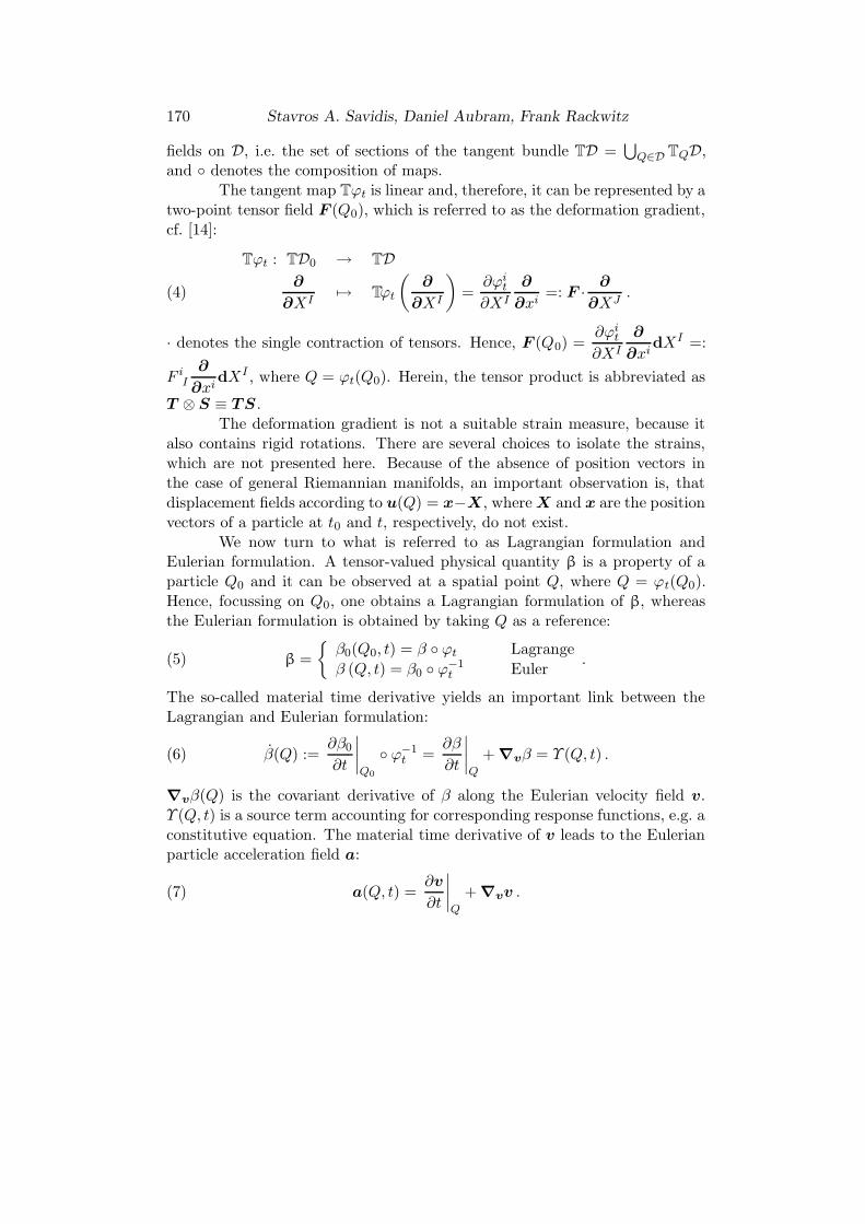
and ◦ denotes the composition of maps.The tangent map Tϕt is linear and, therefore, it can be represented by a
two-point tensor field F (Q0), which is referred to as the deformation gradient,cf. [14]:
Tϕt : TD0 → TD
∂
∂XI7→ Tϕt
(
∂
∂XI
)
=∂ϕi
t
∂XI
∂
∂xi=: F ·
∂
∂XJ.(4)
· denotes the single contraction of tensors. Hence, F (Q0) =∂ϕi
t
∂XI
∂
∂xidXI =:
F iI
∂
∂xidXI , where Q = ϕt(Q0). Herein, the tensor product is abbreviated as
T ⊗ S ≡ TS .The deformation gradient is not a suitable strain measure, because it
also contains rigid rotations. There are several choices to isolate the strains,which are not presented here. Because of the absence of position vectors inthe case of general Riemannian manifolds, an important observation is, thatdisplacement fields according to u(Q) = x−X, where X and x are the positionvectors of a particle at t0 and t, respectively, do not exist.
We now turn to what is referred to as Lagrangian formulation andEulerian formulation. A tensor-valued physical quantity β is a property of aparticle Q0 and it can be observed at a spatial point Q, where Q = ϕt(Q0).Hence, focussing on Q0, one obtains a Lagrangian formulation of β, whereasthe Eulerian formulation is obtained by taking Q as a reference:
(5) β =
{
β0(Q0, t) = β ◦ ϕt Lagrange
β (Q, t) = β0 ◦ ϕ−1t Euler
.
The so-called material time derivative yields an important link between theLagrangian and Eulerian formulation:
(6) β(Q) :=∂β0
∂t
∣
∣
∣
∣
Q0
◦ ϕ−1t =
∂β
∂t
∣
∣
∣
∣
Q
+ ∇vβ = Υ (Q, t) .
∇vβ(Q) is the covariant derivative of β along the Eulerian velocity field v.Υ (Q, t) is a source term accounting for corresponding response functions, e.g. aconstitutive equation. The material time derivative of v leads to the Eulerianparticle acceleration field a:
(7) a(Q, t) =∂v
∂t
∣
∣
∣
∣
Q
+ ∇vv .

Arbitrary Lagrangian-Eulerian Finite Element Formulation. . . 171
It is not necessary to limit the description of a physical quantity to particlesP ↔ Q0 ∈ D0 of the material (Lagrange) or to places Q ∈ D of the ambientspace (Euler) as independent variables. Therefore, an arbitrary reference do-main D ⊂ S can be introduced, assuming the map D → B to be invertible.D consists of open sets of reference points Q and generally depends on time.Figure 2 illustrates the concept.
B
B
D0
D
Q0 Q
P
S
ϕt
κ0
κt
D
Q
Lagrange
Euler
ALE
Ψt Φt
Fig. 2. Arbitrary Lagrangian-Eulerian (ALE) formulation: reference domain D (partof manifold S) and additional mappings Ψt and Φt
Charts with local coordinates χµ are assigned to neighbourhoods of the
Q, such that∂
∂χµ∈ T
QD forms a vector basis at the reference points. As a
general convention, quantities related to the reference domain or to the ALEformulation are denoted by lower case greek letters or by a superposed caret.
A referential map Ψt : D → D0 and a relative map Φt : D → D areintroduced (Fig. 2), both assumed to be invertible and differentiable, i.e. theyare understood as diffeomorphisms. In contrast to ϕt,t0 , Ψt and Φt both reflectno flow or evolution on S ! Obviously, Ψ0 ≡ Φ0 at t = t0. The particle flow in

172 Stavros A. Savidis, Daniel Aubram, Frank Rackwitz
the ambient space now reads
(8) Q(t) = ϕt,t0(Q0) = Φt ◦ Ψ−1t (Q0) ,
where ϕt0,t0(Q0) = Φ0 ◦Φ−10 (Q0) = Q0. Defining coordinate functions Φi
t(Q) =xi ◦ Φt ◦ χ−1 and (Ψ−1
t )µ(Q0) = χµ ◦ Ψ−1t ◦ X−1, for xi = ϕi
t(Q0) one obtains
(9) ϕit(Q0) = xi ◦ Φt ◦ (χ−1 ◦ χ) ◦ Ψ−1
t ◦ X−1 = Φit ◦ (Ψ−1
t )µ .
From the coordinate expressions, it seams reasonable to introduce additionalvelocity fields.
(10)
(
∂(Ψ−1t )µ
∂t
∣
∣
∣
∣
X(Q0)
◦ Ψt
)
∂
∂χµ=: νµ
t (Q)∂
∂χµ∈ Γ(TD)
is the referential velocity field on D and
(11)
(
∂Φit
∂t
∣
∣
∣
∣
χ(Q)
◦ Φ−1t
)
∂
∂xi=: wi
t(Q)∂
∂xi∈ Γ(TD)
is the grid or mesh velocity on D. A substitution of (9) for the spatial velocityv yields
vit(Q) =
∂(xi ◦ Φt ◦ χ−1 ◦ χ ◦ Ψ−1t ◦ X−1)
∂t
∣
∣
∣
∣
X(Q0)
◦ ϕ−1t
=∂Φi
t
∂t
∣
∣
∣
∣
χ(Q)
◦ Φ−1t +
∂Φit
∂χµ
(
∂(Ψ−1t )µ
∂t
∣
∣
∣
∣
X(Q0)
◦ Ψt
)
◦ Φ−1t
= wit(Q) +
((
∂Φit
∂χµνµ
t
)
◦ Φ−1t
)
(Q)(12)
in detail. The second term of the right hand side is of fundamental importanceand is referred to as the convective velocity field:
(13) cit(Q) := vi
t(Q) − wit(Q) or c := v − w ∈ Γ(TD) .
The convective velocity is the relative velocity of particles Q0 and grid pointsQ measured at spatial points Q. From equation (12) and the definitions givenin [14] and references therein, we conclude that c is the pushforward of thereferential velocity field ν:
(14) ct = TΦt ◦ νt ◦ Φ−1t = Φt?νt ∈ Γ(TD) .

Arbitrary Lagrangian-Eulerian Finite Element Formulation. . . 173
The tangent map TΦt is given by
TΦt : TD → TD
∂
∂χµ7→
∂Φit
∂χµ
∂
∂xi.(15)
Lagrangian and Eulerian formulations are special cases of the ALE formulation.If Ψt = IdS is the identity map on S, then c = 0, i.e. the observer moves withthe particles (Lagrange). On the other hand, if Φt = IdS , then c = v, whichstates that the observer is fixed in space (Euler).
2.2. The ALE Operator
By the definition of D, Φt and Ψt, the representation of a physicalquantity β in the reference domain reads
(16) β = β(Q, t) = β(Ψ−1t (Q0), t) = β(Φ−1
t (Q), t) ,
that is, β0 = β◦Ψ−1t and β = β◦Φ−1
t - arguments are suppressed. The materialtime derivative with respect to Q,
(17)˙β =
∂β
∂t
∣
∣
∣
∣
∣
Q
+ ∇ν β = Υ (Q, t) ,
where Υ again is a source term, launches a covariant derivative along ν. If βis a vector field on D, then
(18) ∇ν β (Q) =
(
∂βµ
∂χλνλ + βανλΓ µ
α λ
)
∂
∂χµ∈ T
QD ,
where Γ µα λ are the connexion coefficients (Christoffel symbols) on D. Unfortu-
nately, equation (17) does not incorporate the current placement of the body.However, since ∇ν β is a tensor field and Φt is differentiable, a pushforward op-erator can be established. Recalling the transformation rule of the Christoffelsymbols in R
3, on S one obtains
Γ αµ β (Q) =
∂Φkt
∂χµ
(
∂(Φ−1t )α
∂xi◦ Φt
)
∂Φjt
∂χβ
(
γ ik j ◦ Φt
)
+∂Φk
t
∂χµ
(
∂2(Φ−1t )α
∂xk∂xj◦ Φt
)
∂Φjt
∂χβ,(19)

174 Stavros A. Savidis, Daniel Aubram, Frank Rackwitz
where γ ik j are the connexion coefficients on D. If β is a vector field, then
(20) TΦt
(
∇λβµνλ ∂
∂χµ
)
= ∇jβi
(
∂Φjt
∂χλνλ
)
∂
∂xi= ∇jβ
icj ∂
∂xi
without arguments, that is
(21) ∇cβ = TΦt ◦(
∇ν β)
◦ Φ−1t .
Φt was assumed to be invertible. Hence, one obtains the fundamental result
(22) ∇ν β (Q) = T(Φ−1t ) ◦ (∇cβ) ◦ Φt = Φ?
t (∇cβ(Q))
for all t and any tensor field β. Herein,
T(Φ−1t ) : TD → TD
∂
∂xi→
∂(Φ−1t )µ
∂xi
∂
∂χµ,(23)
where (Φ−1t )µ(Q) := χµ ◦ Φ−1
t ◦ x−1, and Φ?t is the pullback operator concern-
ing Φt. Substitution finally yields the generalised ALE operator for Riemannspaces:
(24)∂β0
∂t
∣
∣
∣
∣
Q0
◦ Ψt =∂β
∂t
∣
∣
∣
∣
∣
Q
+ Φ?t (∇cβ) = Υ (Q, t) .
That is, in ALE formulation, the material time derivative of a quantity β
consists of a local time derivative at fixed reference point Q and a convectiveterm due to the relative motion between the body and the reference domainas measured from a fixed spatial point Q.
3. Nonlinear mechanical behaviour of sand
3.1. Phenomenology
Along with geotechnical construction processes, e.g. during pile pen-etration, the surrounding soil is subjected to different actions and may takeup different material states. The loading paths are often complex, deformationcovers a wide range and the drainage situation may vary. The following sectiongives a brief overview of important mechanical characteristics of sand, whichmake the constitutive modelling rather complicated and renders the governing

Arbitrary Lagrangian-Eulerian Finite Element Formulation. . . 175
-5.0
-2.5
0
2.5
5.0
7.5
0 10 20 30
e = 0.735 (Dr = 64%)
e = 0.832 (Dr = 38%)
e = 0.920 (Dr = 15%)
ε1 [%]
εvo
l = ε
1 + 2ε
3 [%
]
0
500
1000
1500
2000
2500
0 10 20 30
e = 0.735 (Dr = 64%)
e = 0.832 (Dr = 38%)
e = 0.920 (Dr = 15%)
ε1 [%]
q =
σ1 -
σ3 [
kPa]
(a)
(b)
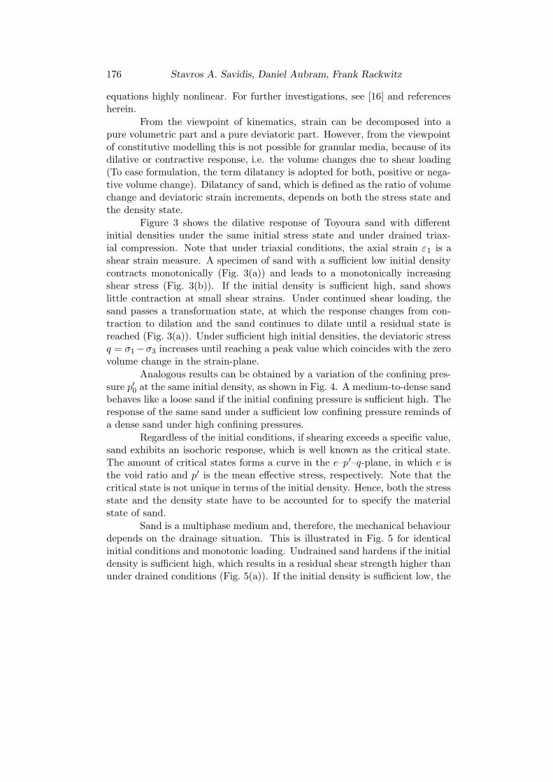
Fig. 3. Dilative behaviour of sand under drained triaxial compression, part I:Dependency on the density state. Toyoura sand, p0 = 1000 kPa
176 Stavros A. Savidis, Daniel Aubram, Frank Rackwitz
equations highly nonlinear. For further investigations, see [16] and referencesherein.
From the viewpoint of kinematics, strain can be decomposed into apure volumetric part and a pure deviatoric part. However, from the viewpointof constitutive modelling this is not possible for granular media, because of itsdilative or contractive response, i.e. the volume changes due to shear loading(To ease formulation, the term dilatancy is adopted for both, positive or nega-tive volume change). Dilatancy of sand, which is defined as the ratio of volumechange and deviatoric strain increments, depends on both the stress state andthe density state.
Figure 3 shows the dilative response of Toyoura sand with differentinitial densities under the same initial stress state and under drained triax-ial compression. Note that under triaxial conditions, the axial strain ε1 is ashear strain measure. A specimen of sand with a sufficient low initial densitycontracts monotonically (Fig. 3(a)) and leads to a monotonically increasingshear stress (Fig. 3(b)). If the initial density is sufficient high, sand showslittle contraction at small shear strains. Under continued shear loading, thesand passes a transformation state, at which the response changes from con-traction to dilation and the sand continues to dilate until a residual state isreached (Fig. 3(a)). Under sufficient high initial densities, the deviatoric stressq = σ1 −σ3 increases until reaching a peak value which coincides with the zerovolume change in the strain-plane.
Analogous results can be obtained by a variation of the confining pres-sure p′0 at the same initial density, as shown in Fig. 4. A medium-to-dense sandbehaves like a loose sand if the initial confining pressure is sufficient high. Theresponse of the same sand under a sufficient low confining pressure reminds ofa dense sand under high confining pressures.
Regardless of the initial conditions, if shearing exceeds a specific value,sand exhibits an isochoric response, which is well known as the critical state.The amount of critical states forms a curve in the e–p′–q-plane, in which e isthe void ratio and p′ is the mean effective stress, respectively. Note that thecritical state is not unique in terms of the initial density. Hence, both the stressstate and the density state have to be accounted for to specify the materialstate of sand.
Sand is a multiphase medium and, therefore, the mechanical behaviourdepends on the drainage situation. This is illustrated in Fig. 5 for identicalinitial conditions and monotonic loading. Undrained sand hardens if the initialdensity is sufficient high, which results in a residual shear strength higher thanunder drained conditions (Fig. 5(a)). If the initial density is sufficient low, the

Arbitrary Lagrangian-Eulerian Finite Element Formulation. . . 177
-10.0
-7.5
-5.0
-2.5
0
2.5
0 10 20 30
p'0 = 2000 kPa
p'0 = 1000 kPa
p'0 = 100 kPa
ε1 [%]
εvo
l = ε
1 + 2ε
3 [%
]
0
1000
2000
3000
4000
5000
0 10 20 30
p'0 = 2000 kPa
p'0 = 1000 kPa
p'0 = 100 kPa
ε1 [%]
q =
σ1 -
σ3 [
kPa]
(a)
(b)
Fig. 4. Dilative behaviour of sand under drained triaxial compression, part II:Dependency on the stress state. Toyoura sand, e0 = 0.735 (Dr0 = 64 %)

178 Stavros A. Savidis, Daniel Aubram, Frank Rackwitz
0
1000
2000
3000
4000
0 5 10 15 20 25
drained
undrained
e0 = 0.735 (Dr = 64%)
ε1 [%]
q =
σ1 -
σ3 [
kPa]
0
500
1000
1500
2000
2500
0 5 10 15 20 25
undrained
drained
e0 = 0.920 (Dr = 15%)
ε1 [%]
q =
σ1 -
σ3 [
kPa]
(a)
(b)
Fig. 5. Behaviour of sand under drained and undrained conditions at different initialdensities. Toyoura sand, p0 = 1000 kPa

Arbitrary Lagrangian-Eulerian Finite Element Formulation. . . 179
-80
-40
0
40
80
-0.4 -0.3 -0.2 -0.1 0 0.1
γ = ε1 - ε
3 [-]
q =
σ1 -
σ3 [
kPa]
(a)
(b)
-80
-40
0
40
80
0 100 200 300
p' = (σ'1 + 2σ'
3) / 3 [kPa]
q =
σ1 -
σ3 [
kPa]
Fig. 6. Behaviour of sand under undrained cyclic triaxial conditions. Toyoura sand,e0 = 0.920 (Dr0 = 15 %)

180 Stavros A. Savidis, Daniel Aubram, Frank Rackwitz
-80
-40
0
40
80
0 100 200 300
p' = (σ'1 + 2σ'
3) / 3 [kPa]
q =
σ1 -
σ3 [
kPa]
(a)
(b)
-80
-40
0
40
80
-0.04 -0.02 0 0.02γ = ε
1 - ε
3 [-]
q =
σ1 -
σ3 [
kPa]
Fig. 7. Behaviour of sand under undrained cyclic triaxial conditions. Toyoura sand,e0 = 0.735 (Dr0 = 64 %).

Arbitrary Lagrangian-Eulerian Finite Element Formulation. . . 181
effective mean normal stress and the shear strength drop dramatically, due tothe loss of particle contacts (Fig. 5(b)).
The above mentioned characteristics under undrained conditions areof utmost importance under cyclic loading conditions, because the loadingdirection changes faster than the soil consolidates due to the changed loadingconditions. As shown in Figs 6 and 7, the rearrangement of grains and thedilatancy of sand leads to an excessive pore pressure build up, followed by adecrease of both the mean effective stress and the shear stiffness. Dependenton the confining pressure and the loading amplitude, an initially loose sandmay be subjected to a complete loss of shear resistance and undergoes a largeshear deformation, due to gradually increasing excessive pore pressure (Fig. 6).This phenomenon is also referred to as liquefaction. In contrast to that, if thesand is sufficient dense, it regains its shear stiffness after a couple of loadingcycles and shows cyclic mobility by limiting shear deformation (Fig. 7).
3.2. Constitutive equations
In the last decades, a large amount of constitutive equations for soilhas been developed, which makes the choice for the user almost unmanageable.However, only a few contributions simulate the mechanical behaviour of sandunder complex loading paths over a wide range of densities and stress statesusing a single set of parameters. The most popular fall into the groups ofelastoplastic or hyperelastoplastic models and hypoplastic models.
Although deformations are often large in geomechanics, e.g. in triax-ial and oedometer test settings, at slope failure or during pile penetration,the finite strain formulation of hyperelastoplastic soil models is an exception.Mostly, strains are assumed to be small and the elastic and plastic strains aredecomposed additively. In finite strain hyperelastoplasticity, a common ap-proach is to split the deformation gradient into an elastic and a plastic partmultiplicatively [15]. A crucial point is, that hyperelastoplastic constitutiveequations require the information of deformation as a whole, i.e. the deforma-tion occurred from the initial to the current placement.
By contrast, the class of hypoplastic models comprehends constitutiveequations of the rate type together with a specification for finite strains [17].The general hypoplastic constitutive equation reads
(25)◦
σ = h(σ,d, αi),
in which◦
σ denotes an objective stress rate, σ is the Cauchy stress, d is thespatial (Eulerian) rate of deformation tensor and αi are some internal variables

182 Stavros A. Savidis, Daniel Aubram, Frank Rackwitz
accounting for the state of the material. The spatial covariant hypoplasticresponse function h has to be isotropic, cf. [17], and it is nonlinear in d.In geomechanics, hypoplastic models were firstly developed by Gudehus &Kolymbas [18]. A model for sand of the general form
◦
σ = h(σ,d, e), in whiche denotes the void ratio, has been extended by Niemunis & Herle [19] for cyclicloading conditions by introducing a so-called intergranular strain.
Recalling that arbitrary Lagrangian-Eulerian formulation covers largedeformations and an initial placement of the body is usually unavailable, itseems reasonable to implement a rate type model for the ALE simulation ofpile penetration. In fact, this decision can be seen as a standard in the ALEcommunity.
4. Finite element implementation
The finite strains in the vicinity of the pile tip and the mechanical be-haviour of sand render the pile penetration problem highly nonlinear. Thereare several choices to solve the ALE Operator numerically, by either finitedifference methods or finite element methods. A simple arbitrary Lagrangian-Eulerian (SALE) method is restricted to a single material in each elementand the boundaries are resolved explicitly by element edges, i.e. they re-main Lagrangian (Fig. 8). In a multi-material arbitrary Lagrangian-Eulerian(MMALE) method, different materials can ”flow” through the mesh. The ele-ment edges are, in general, not aligned with the material boundaries [7]. In thefollowing sections, the implementation of the SALE strategy into an implicitLagrangian finite element code is described.
Fig. 8. Simple arbitrary Lagrangian-Eulerian (SALE) and Multi-Material ArbitraryLagrangian-Eulerian (MMALE) formulations. Figure from [7]

Arbitrary Lagrangian-Eulerian Finite Element Formulation. . . 183
4.1. Operator-split
A crucial point of the ALE framework is the handling of the convec-tive terms, which emerge from the time-dependency of the reference domain.This is of particular importance if path-dependent materials are involved. If anoperator-split [6] of the complicated governing equations is applied, the neededalgorithms are usually simpler and more robust than algorithms for the fullycoupled problem. Another advantage growth from the facility to upgrade ex-isting Lagrangian finite element programmes as presented herein, using thecommercial code ANSYS.
Applying the operator-split to equation (24),
(26)∂β0
∂t
∣
∣
∣
∣
Q0
= Υ0(Q0, t) and∂β
∂t
∣
∣
∣
∣
∣
Q
+ Φ?t (∇cβ) = 0 ,
this yields a parabolic and a homogenous hyperbolic differential equation. Thesolution of the split ALE methods then proceeds in three steps. In the first step,the parabolic equation (26)1 is solved. Since there is no difference to classicalapproaches in solid mechanics using Lagrangian finite element codes, this stepis referred to as the Lagrangian phase. Nonlinear constitutive equations canbe incorporated in a well-established way.
Especially during the simulation of penetration, forging and extrusionprocesses, heavy element distortion may occur, if the mesh moves with thematerial. The intention of the second step is to reduced these distortions byapplying suitable rezoning or mesh smoothing techniques. Complete remesh-ing, that goes along with a modification of the mesh topology, only becomesnecessary at significant changes in shape of the domain. The material state is”frozen” in the smoothing phase. Although numerous algorithms are available,only a few of them manage smoothing of non-convex mesh regions sufficiently.
In the last solution step, the convection phase, the variables β of theLagrangian phase are mapped to the updated mesh concerning equation (26)2.Computational fluid dynamics provides several effective algorithms to solveequation (26)2 with high accuracy, even if the calculation results of the La-grangian phase are discontinuous across finite element edges. Note that theLagrangian phase, the smoothing phase and the convection phase take placein the same physical time increment. However, time is a dummy parameter inquasi static analyses.

184 Stavros A. Savidis, Daniel Aubram, Frank Rackwitz
4.2. Mesh smoothing schemes
An important ingredient of realistic and accurate finite element sim-ulations is the quality of the mesh. Highly squeezed and distorted elementsshould be avoided, as well as crowding of nodes in regions of secondary inter-est. The former, referred to as mesh smoothing if the mesh topology alreadyexists, can be achieved by a priori limitation of geometric criterions, while thelatter, referred to as mesh adaption, requires physical results obtained throughcalculation. By applying the operator-split ALE framework to the finite el-ement method, it becomes possible for the user to optimise the mesh afterthe Lagrangian phase of calculations. If the topology is kept unchanged anda physical criterion for the mesh quality is used, the ALE framework can beseen as a r-adaption of the finite element mesh. However, the focus in thispaper is on mesh smoothing schemes rather than adaptive techniques to opti-mise the mesh, because advantages of the ALE formulation thus would be besthighlighted.
A distinction is drawn between the nodes to be moved in order tosmooth the mesh. For internal nodes, there is a large amount of mesh smooth-ing algorithms available. Transfinite mapping and Laplacian methods are alsopopular for mesh generation. Simple barycentric smoothing or averaging pro-cedures [20] move internal nodes to the centroid of the associated element patchand offer low implementation cost. Unfortunately, all these methods only suc-ceed if the boundaries or domains respectively are convex. If the boundariesare non-convex, such as the soil regions around a pile tip at deep penetration,internal nodes may run outside so that the mesh gets folded. Algorithms whichovercome mesh folding even in unstructured meshes are, for example, Winslowsmoothing [21], Giuliani smoothing [22] and energy based methods [23], [24].
As shown in [23], the profit of appropriate smoothing schemes for inter-nal nodes is limited, if the location of the boundary nodes remains unchanged.In two-dimensional meshes, boundaries can simply be smoothed by averagingprocedures in order to improve the quality of the complete mesh considerably[20]. Corner nodes of the domain are not moved, because they shape thedomain.
From the viewpoint of mesh smoothing, in a high quality mesh noelement becomes too large and each element has low distortion. An importantmeasure for the squeeze and distortion of triangular elements is the ratio ofradii of the circumcircle rout and the incircle rin, respectively. The ratio isrout/rin = 2.0 for equilateral triangles and approaches infinity if the elementdegenerates. From this, Braess & Wriggers [23] propose the potential

Arbitrary Lagrangian-Eulerian Finite Element Formulation. . . 185
(27) W =∑
elements
ω =∑
elements
rout
r0
(
rout
rin
)3
= Min,
which has to be minimised. r0 = 1.0 is a reference radius. Choosing ap-propriate r0 for each element, W can also be applied to h-adaptive meshingalgorithms.
It is sufficient to reach a local minimum of the potential in terms ofelement patches enclosing a single internal node. Therefore, the sum in equa-tion (27) is over the number of elements in the patch and standard minimisationalgorithms, such as Newton’s method, can be applied. Making it more con-
crete, trigonometry features rout =a b c
4Aand rin =
A
s, where A is the area, s is
half the perimeter and a, b, c are the edge lengths of the triangle, respectively.Let xint denote the location of the internal node, then
(28) W = Min ⇐⇒∂W
∂xint= 0
and, performing Newton’s method,
(29) xj+1int = x
jint −
(
∂2W j
∂(xjint)
2
)−1∂W j
∂xjint
.
4.3. Convection phase
In the convection phase, the variables β calculated in the Lagrangianphase are mapped on the smoothed mesh, according to equation (26)2. Thesmoothing phase results in the mesh velocity field. Together with the materialvelocity of the Lagrangian phase, from equation (13) the convective velocitycan be obtained. Note that on the boundary of the domain and on the materialinterfaces, the normal components of the relative velocity between the materialand the mesh are zero in SALE methods.
In R3, let xn, xL, xn+1 denote the location of the mesh nodes at
the beginning of the time step, after the Lagrangian phase and after the
smoothing phase, respectively. Then v =xL − xn
∆tis the material velocity,
w =xn+1 − xn
∆tis the mesh velocity and c =
xL − xn+1
∆tis the convective ve-
locity. For the solution of equation (26)2, explicit time integration schemes are

186 Stavros A. Savidis, Daniel Aubram, Frank Rackwitz
preferred. Explicit convection algorithms are conditional stable, if the materialdoes not pass an element within one step, i.e. if the Courant-Friedrichs-Lewycondition is fulfilled:
(30) c∆t = xL − x
n+1 ≤ h,
h is a characteristic element size, e.g. an edge length. In the case of quasistaticanalyses, ∆t is a dummy and (30) requires the load increment not to be toolarge.
The implementation of the convection phase plays a fundamental role inarbitrary Lagrangian-Eulerian methods. Therein, the main challenge is foundin the determination of the gradient in equation (26)2, because variables aretypically evaluated at the Gauss points and not at the element nodes. There-fore, they are discontinuous across the element edges. Two overall strategiesare established in the ALE community. One possible approach is to smooththe β field, e.g. by least square approximation [9], in order to obtain a smoothgradient field and then apply Lax-Wendroff or Taylor-Galerkin algorithms, re-spectively [25]. Another way is to construct cells where β is constant, that isone cell per Gauss point, and then solve this Riemann problem by Godunov-type techniques, as known from computational fluid dynamics. For the two-dimensinal case (triangular elements), Rodrıguez-Ferran et al. [25] propose theformula
(31) βn+1 = βL −∆t
2A
3∑
i=1
fSi
(
βcSi
− βL)
(1 − sign (fSi)) ,
in which βL and βn+1 denote the physical quantity after the Lagrangian phaseand at the end of the load step, respectively, βc
Siis the physical quantity in
the contiguous element owning the shared element edge Si and sign (·) is thesign function.
(32) fSi=
∫
S
(n∗ · c) dSi
is the flux of the convective velocity field across the element edge Si, with n∗
as the unit normal field on the element boundary S . Equation (31) has to beevaluated for each element.
5. Numerical examples
The ALE framework has been implemented into the commercial im-plicit Lagrangian finite element code ANSYS [26] for subsequent analyses, by
Arbitrary Lagrangian-Eulerian Finite Element Formulation. . . 187
applying the operator-split to the governing equations. The code providesseveral user-interfaces for customisation, including user-defined constitutiveequations and routines for accessing the database.
Three different mesh smoothing algorithms have been implemented:barycentric smoothing [20], Giuliani smoothing [22] and energy-based smooth-ing [23]. In the following, some numerical examples are presented which high-light the advantages and drawbacks of each algorithm, keeping in mind thefollowing characteristics of pile penetration. First, during penetration, the soilregions around the pile tip are necessarily non-convex, dependent on the geom-etry of the pile tip. Second, at sufficient slippery contact conditions betweenthe pile and the soil, a dagger-like pile tip primarily displaces the soil in lateraldirection, whereas a flat pile tip causes heavy soil compression directly belowthe tip - the latter leads to severe element squeezing in pure Lagrangian cal-culations. The focus in this paper is on numerical examples involving bothmechanisms, such as a coining test and back extrusion problem.
5.1. Coining test
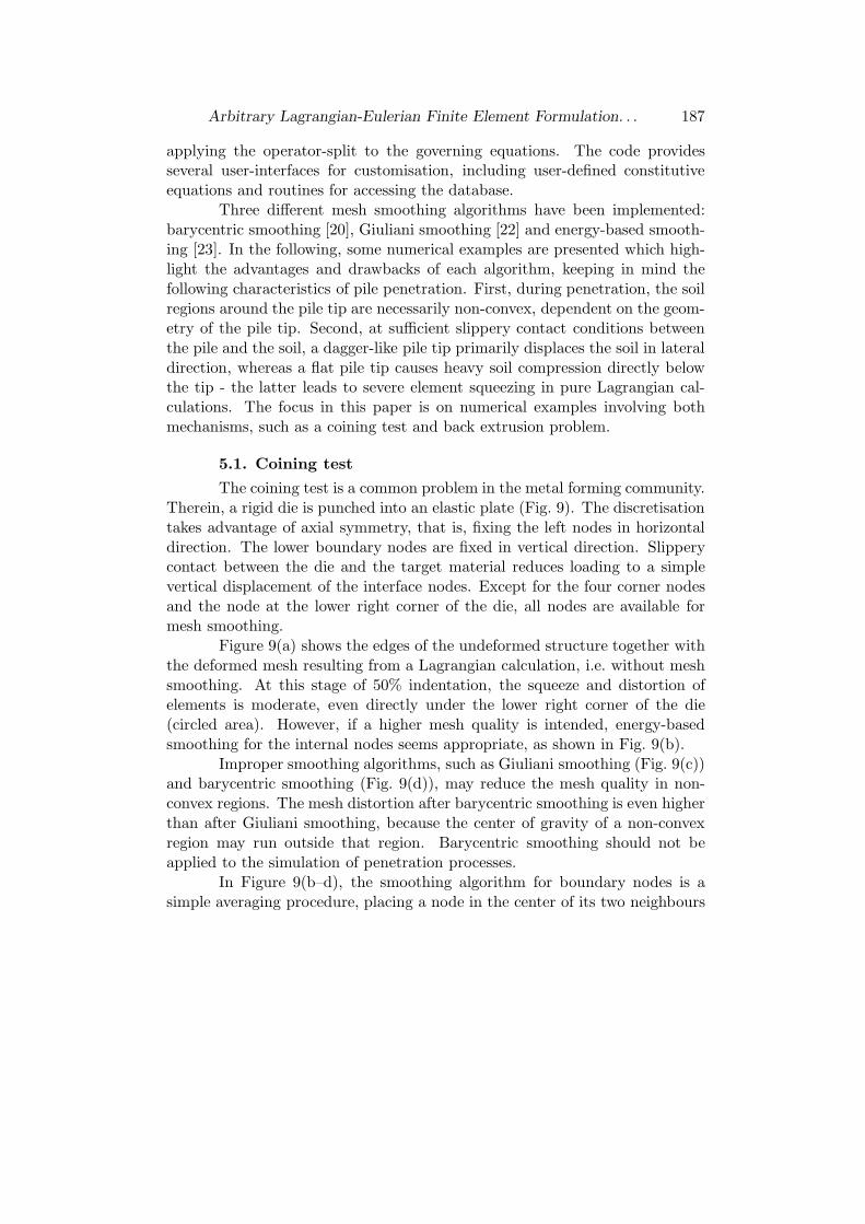
The coining test is a common problem in the metal forming community.Therein, a rigid die is punched into an elastic plate (Fig. 9). The discretisationtakes advantage of axial symmetry, that is, fixing the left nodes in horizontaldirection. The lower boundary nodes are fixed in vertical direction. Slipperycontact between the die and the target material reduces loading to a simplevertical displacement of the interface nodes. Except for the four corner nodesand the node at the lower right corner of the die, all nodes are available formesh smoothing.
Figure 9(a) shows the edges of the undeformed structure together withthe deformed mesh resulting from a Lagrangian calculation, i.e. without meshsmoothing. At this stage of 50% indentation, the squeeze and distortion ofelements is moderate, even directly under the lower right corner of the die(circled area). However, if a higher mesh quality is intended, energy-basedsmoothing for the internal nodes seems appropriate, as shown in Fig. 9(b).
Improper smoothing algorithms, such as Giuliani smoothing (Fig. 9(c))and barycentric smoothing (Fig. 9(d)), may reduce the mesh quality in non-convex regions. The mesh distortion after barycentric smoothing is even higherthan after Giuliani smoothing, because the center of gravity of a non-convexregion may run outside that region. Barycentric smoothing should not beapplied to the simulation of penetration processes.
In Figure 9(b–d), the smoothing algorithm for boundary nodes is asimple averaging procedure, placing a node in the center of its two neighbours

188 Stavros A. Savidis, Daniel Aubram, Frank Rackwitz
a) Lagrange b) ALE, energy-based smoothing
c) ALE, Giuliani smoothing d) ALE, barycentric smoothing
undeformed domain
rigid die
demanding region for
mesh smoothing
Fig. 9. Comparison of different mesh smoothing schemes applied to the numericalsimulation of a coining test at the stage of 50% indentation. (a) Lagrangian mesh
and ALE mesh with (b) energy-based smoothing, (c) Giuliani smoothing, (d)barycentric smoothing
on a parabola [20].
5.2. Back extrusion problem
The boundary conditions of a back extrusion problem (Fig. 10) aresimilar to the coining test, except for the suppression of the horizontal dis-placements of the vertical aligned nodes on the vertical boundaries.
Figure 10 top shows the edges of the undeformed structure togetherwith the deformed mesh at 30% indentation. The left hand side illustrates theresults of the calculation using Giuliani’s scheme for mesh smoothing, whereasthe mesh on the right hand side results from the energy-based smoothing al-gorithm. The mesh quality of regions directly below the die is comparable atthis stage. Near the lower boundary, the energy-based algorithm produces aslightly smoother mesh. At 50% indentation and applying Giuliani smoothing,elements around the corner of the die are extremely squeezed. The area of one

Arbitrary Lagrangian-Eulerian Finite Element Formulation. . . 189
30 %
Giuliani smoothing Energy-based smoothing
50 %
71 %
Solution not converged.
Fig. 10. Comparison of Giuliani smoothing and energy-based smoothing applied tothe numerical simulation of a back extrusion problem at different indentations

190 Stavros A. Savidis, Daniel Aubram, Frank Rackwitz
element even vanishes, which inhibits the convergence of the solution at higherindentation.
Compared to Giuliani smoothing, energy-based smoothing achieves agood mesh regularisation. At 50% indentation, the squeeze and distortionof elements is moderate, even directly below the die. However, at higher in-dentation, the rigid mesh topology together with the simplified local form ofequation (27), i.e. to achieve a local instead of a global minimum, limits gainsof mesh quality. Calculation terminates at indentations of more than 71%.Only complete remeshing would eliminate element degeneration in order toensure a convergent solution.
5.3. Penetration of a rigid pile
Figure 11 illustrates simulation results of the penetration of a rigid pileinto elastic soil material, assuming slippery contact conditions between thepile and the soil. The finite element mesh after a classical updated Lagrangiancalculation is shown on the left. Elements below the round pile tip are heavilysqueezed. The area of the first element row even vanishes, as brought out bythe detail. On the other hand, elements next to the pile at the free surface arestretched, thus reducing the density of nodes and the accuracy of the resultsin regions of a strong solution gradient.
Figure 11 on the right shows the results of the simulation by using anALE formulation of finite elements. The mesh is obtained through an energy-based smoothing of the internal nodes and a simple averaging procedure for theboundary nodes. From the detail, it can be seen that the problematic regionsdiscussed profit from the mesh regularisation. Squeezing of elements below thepile tip is pretty reduced. The averaging procedure for the free surface nodesnaturally avoids large stretching of the associated elements and maintains theinitial density of nodes lateral to the pile. Compared to barycentric smoothingand Giuliani smoothing, the energy-based scheme yields the best results.
6. Summary
A framework for the finite element simulation of geotechnical construc-tion processes in sandy soil has been presented. It is based on the SimpleArbitrary Lagrangian-Eulerian (SALE) method. For the numerical implemen-tation, an operator-split has been applied in order to enforce simpler equationsand to achieve the possibility to update an existing Lagrangian finite elementcode with an implicit global time integration. Three different mesh smooth-ing schemes have been implemented and applied to different boundary value

Arbitrary Lagrangian-Eulerian Finite Element Formulation. . . 191
Lagrange ALE
Detail
Fig. 11. Numerical simulation of the penetration of a smooth rigid pile into elasticmaterial. left: Lagrangian mesh, right: ALE mesh with energy-based smoothing

192 Stavros A. Savidis, Daniel Aubram, Frank Rackwitz
problems. It has been shown by the numerical simulations of a coining test, aback extrusion problem and pile penetration, that handling non-convex meshregions is an important task that has to be captured by an adequate scheme.
The results presented are based on the assumption of an elastic mater-ial. Further developments should incorporate an advanced hypoplastic consti-tutive equation, which is able to model the surrounding soil, especially sand, incontext of ALE more realistically. In this case, the numerical implementationis more complicated and the choice of the numerical algorithms for the convec-tion phase plays an important role, since convective terms affect the update ofthe state variables of the governing equations.
The SALE method is appropriate to simulate pile penetration into soil.However, for geotechnical construction processes which involve very large ma-terial deformations, such as grouting and mixing, it seems reasonable to applyMulti-Material Arbitrary Lagrangian-Eulerian (MMALE) methods, becausethe material boundaries cannot be resolved explicitly by element edges.
Appendix. Symbols and Notation
A, B, C, . . . sets, vector spaces;A,B, C, . . . manifolds;
a, b,S,T , . . . vectors, tensors (direct notation);T · S 6= S · T single contraction of tensors;
T ⊗ S ≡ TS 6= ST tensor product, dyadic product;TPM = {P} × Vndim
ndim-dimensional tangent space at P ∈ M;T∗PM co-tangent space (dual space);
TM =⋃
P∈MTPM tangent bundle;
Tφ : TA → TB tangent map, differential of a map φ : A → B;φ?, φ? pushforward, pullback concerning φ;
∂
∂xi , dxi base vectors, dual base vectorsΓ set of vector or tensor fields (bundle section);
∇v covariant derivative along v;f ◦ g = f(g) composition of maps;
I, J,K, . . . coordinate indices (Lagrangian formulation);i, j, k, . . . coordinate indices (Eulerian formulation);
α, β, γ, . . . coordinate indices (ALE formulation).

Arbitrary Lagrangian-Eulerian Finite Element Formulation. . . 193
REFEREN CES
[1] Savidis, S. A., J. Mittag. Vibration Measurements in Deep Excavation Pitsin Berlin, Proceedings Civil and Environmental Engineering Conference – NewFrontiers and Challenges, Bangkok, Thailand, 1999, II-49–II-54.
[2] Triantafyllidis, T. Neue Erkenntnisse aus Messungen an tiefen Baugrubenam Potsdamer Platz in Berlin. Bautechnik, 75 (1998) No 3, 133–154 (in Ger-man).
[3] Armero, F., E. Love. An Arbitrary Lagrangian-Eulerian Finite ElementMethod for Finite Strain Plasticity. International Journal for Numerical Meth-
ods in Engineering, 57 (2003), 471–508.[4] Hirt, C. W., A. A. Amsden, J. L. Cook. An Arbitrary Lagrangian-Eulerian
Computing Method for All Flow Speeds. Journal for Computational Physics,14, (1974), 227–253.
[5] Donea, J., A. Huerta, J.-P. Ponthot, A. Rodrıguez-Ferran. ArbitraryLagrangian-Eulerian Methods, Encyclopedia of Computational Mechanics (EdsE. Stein et al.), New York, John Wiley & Sons, 2004.
[6] Benson, D. J. An Efficient, Accurate, Simple ALE Method for Nonlinear FiniteElement Programs. Computer Methods in Applied Mechanics and Engineering,72 (1989), 305–350.
[7] Freßmann, D., P. Wriggers. Advection Approaches for Single- and Multi-Material Arbitrary Lagrangian-Eulerian Finite Element Procedures. Computa-
tional Mechanics, 39 (2007), 153–190.[8] Hughes, T. J. R., W. K. Liu, T. K. Zimmermann. Lagrangian-Eulerian
Formulation for Incompressible Viscous Flows. Computer Methods in Applied
Mechanics and Engineering, 29 (1981), 329–349.[9] Huetink, J., P. T. Vreede, J. Van Der Lugt. Progress in Mixed
Lagrangian-Eulerian Finite Element Simulation of Forming Processes. Inter-
national Journal for Numerical Methods in Engineering, 30 (1990), 1441–1457.[10] Van den Berg, P. Analysis of Soil Penetration, PhD Thesis, Delft University,
The Netherlands, 1994.[11] Susila, E., R. D. Hryciw. Large Displacement FEM Modelling of the Cone
Penetration Test (CPT) in Normally Consolidated Sand. International Journal
for Numerical and Analytical Methods in Geomechanics, 27 (2003), 585–602.[12] Bishop, R. L., S. I. Goldberg. Tensor Analysis on Manifolds, New York,
The Macmillan Company, 1968.[13] Abraham, R., J. E. Marsden. Foundations of Mechanics, second ed.,
Addison-Wesley, Reading, MA, 1978.[14] Marsden, J. E., T. J. R. Hughes. Mathematical Foundations of Elasticity,
Dover Publications, 1994.[15] Simo, J. C. A Framework for Finite Strain Elastoplasticity Based on Maxi-
mum Plastic Dissipation and the Multiplicative Decomposition: Part I. Contin-uum Formulation. Computer Methods in Applied Mechanics and Engineering,66 (1988), 199–219.

194 Stavros A. Savidis, Daniel Aubram, Frank Rackwitz
[16] Savidis, S. A., D. Aubram, X. S. Li, F. Rackwitz. Numerical Modellingof Non-linear Soil Behaviour under Seismic Loading Conditions. Soil Dynamics
and Earthquake Engineering, (2007), (submitted).
[17] Truesdell, C., W. Noll. The Non-Linear Field Theories of Mechanics,Berlin-Heidelberg-New York, 3. Auflage, Springer-Verlag, 2004.
[18] Gudehus, G., D. Kolymbas. A Constitutive Law of the Rate Type for Soils.Proceedings of the Third International Conference on Numerical Methods inGeomechanics, 319–329, Aachen, Germany, 1979.
[19] Niemunis, A., I. Herle. Hypoplastic Model for Cohesionless Soils with ElasticStrain Range. Mechanics of Cohesive-Frictional Materials, 2 (1997), 279–299.
[20] Aymone, J. L. F. Mesh Motion Techniques for the ALE Formulation in 3DLarge Deformation Problems. International Journal for Numerical Methods in
Engineering, 59 (2004), 1879–1908.
[21] Knupp, P. M. Winslow Smoothing on Two-Dimensional Unstructured Meshes.Engineering with Computers, 15 (1999), 263–268.
[22] Giuliani, P. M. An Algorithm for Continuous Rezoning of the HydrodynamicGrid in Arbitrary Lagrangian-Eulerian Computer Codes. Nuclear Engineering
and Design, 72 (1982), 205–212.
[23] Braess, H., P. Wriggers. Arbitrary Lagrangian Eulerian Finite ElementAnalysis of Free Surface Flow. Computer Methods in Applied Mechanics and
Engineering, 190 (2000), 95–109.
[24] Joun, M. S., M. C. Lee. Quadrilateral Finite-Element Generation and MeshQuality Control for Metal Forming Simulation. International Journal for Nu-
merical Methods in Engineering, 40 (1997), 4059–4075.
[25] Rodrıguez-Ferran, A., F. Casadei, A. Huerta. ALE Stress Update forTransient and Quasistatic Processes. International Journal for Numerical Meth-
ods in Engineering, 43 (2004), 241–262.
[26] ANSYS (2004). Guide to ANSYS User Programmable Features – ANSYS Re-lease 8.1. ANSYS, Inc., No. 001975, April 2004.