eighth edition - welcome to apl100 -...
TRANSCRIPT

VECTOR MECHANICS FOR ENGINEERS:
STATICS
Eighth Edition
Ferdinand P. Beer
E. Russell Johnston, Jr.
Lecture Notes:
J. Walt Oler
Texas Tech University
CHAPTER
© 2007 The McGraw-Hill Companies, Inc. All rights reserved.
4 Equilibrium of
Rigid Bodies

© 2007 The McGraw-Hill Companies, Inc. All rights reserved.
Vector Mechanics for Engineers: Statics
Eig
hth
E
ditio
n
4 - 2
Contents
Introduction
Free-Body Diagram
Reactions at Supports and Connections for
a Two-Dimensional Structure
Equilibrium of a Rigid Body in Two
Dimensions
Statically Indeterminate Reactions
© 2007 The McGraw-Hill Companies, Inc. All rights reserved.
Vector Mechanics for Engineers: Statics
Eig
hth
E
ditio
n
4 - 3
Contents
Sample Problem 4.1
Sample Problem 4.3
Sample Problem 4.4
Equilibrium of a Two-Force Body
Equilibrium of a Three-Force Body
Sample Problem 4.6

© 2007 The McGraw-Hill Companies, Inc. All rights reserved.
Vector Mechanics for Engineers: Statics
Eig
hth
E
ditio
n
4 - 4
Contents
Equilibrium of a Rigid Body in Three
Dimensions
Reactions at Supports and Connections
for a Three-Dimensional Structure
Sample Problem 4.8

© 2007 The McGraw-Hill Companies, Inc. All rights reserved.
Vector Mechanics for Engineers: Statics
Eig
hth
E
ditio
n
Introduction
•For a rigid body in static equilibrium, the external forces and moments are balanced and will impart no translational or rotational motion to the body.

© 2004 The McGraw-Hill Companies, Inc. All rights reserved.
Se
ve
nth
E
ditio
n
Equilibrium Essentiality
The force and couple
moment system acting on a
body can be reduced to an
equivalent resultant force
and resultant couple moment
at any arbitrary point O on
or off the body.

© 2004 The McGraw-Hill Companies, Inc. All rights reserved.
Se
ve
nth
E
ditio
n
Equilibrium Essentiality
lf this resultant force and
couple moment are both
equal to zero, then the
body is said to be in
equilibrium
FR = 0 and ( MR)O = 0

© 2004 The McGraw-Hill Companies, Inc. All rights reserved.
Se
ve
nth
E
ditio
n
000
000
zyx
zyx
MMM
FFF
•Resolving each force and moment into its rectangular components leads to 6 scalar equations which also express the conditions for static equilibrium,
© 2004 The McGraw-Hill Companies, Inc. All rights reserved.
Se
ve
nth
E
ditio
n
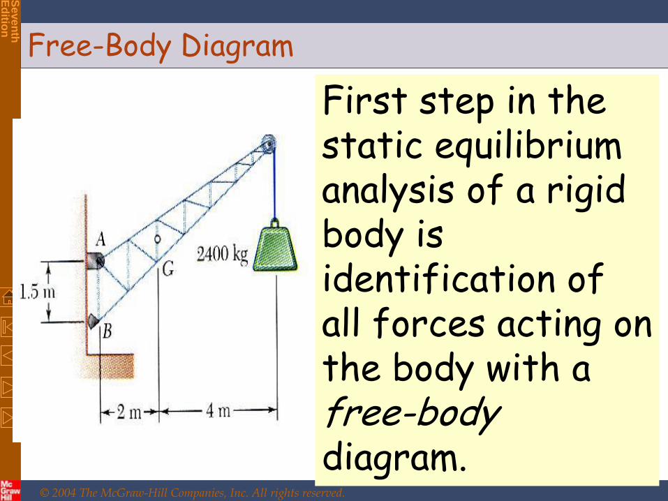
First step in the static equilibrium analysis of a rigid body is identification of all forces acting on the body with a free-body diagram.
Free-Body Diagram

© 2004 The McGraw-Hill Companies, Inc. All rights reserved.
Se
ve
nth
E
ditio
n •Select the extent of the free-body and detach it from the ground and all other bodies.
•Indicate point of application, magnitude, and direction of external forces, including the rigid body weight.

© 2004 The McGraw-Hill Companies, Inc. All rights reserved.
Se
ve
nth
E
ditio
n •Indicate point of application and
assumed direction of unknown applied forces. These usually consist of reactions through which the ground and other bodies oppose the possible motion of the rigid body.
•Include the dimensions necessary to compute the moments of the forces.

© 2007 The McGraw-Hill Companies, Inc. All rights reserved.
Vector Mechanics for Engineers: Statics
Eig
hth
E
ditio
n
4 - 12
Reactions at Supports and Connections for a
Two-Dimensional Structure
•Reactions
equivalent
to a force
with
known
line of
action.

© 2007 The McGraw-Hill Companies, Inc. All rights reserved.
Vector Mechanics for Engineers: Statics
Eig
hth
E
ditio
n
4 - 13
Reactions at Supports and Connections for a
Two-Dimensional Structure
•Reactions equivalent to a force of
unknown direction and magnitude.

© 2007 The McGraw-Hill Companies, Inc. All rights reserved.
Vector Mechanics for Engineers: Statics
Eig
hth
E
ditio
n
4 - 14
Reactions at Supports and Connections for a Two-
Dimensional Structure
•Reactions equivalent to a force of
unknown direction and magnitude and
a couple of unknown magnitude

© 2007 The McGraw-Hill Companies, Inc. All rights reserved.
Vector Mechanics for Engineers: Statics
Eig
hth
E
ditio
n
4 - 15

© 2007 The McGraw-Hill Companies, Inc. All rights reserved.
Vector Mechanics for Engineers: Statics
Eig
hth
E
ditio
n

© 2007 The McGraw-Hill Companies, Inc. All rights reserved.
Vector Mechanics for Engineers: Statics
Eig
hth
E
ditio
n

© 2007 The McGraw-Hill Companies, Inc. All rights reserved.
Vector Mechanics for Engineers: Statics
Eig
hth
E
ditio
n

© 2007 The McGraw-Hill Companies, Inc. All rights reserved.
Vector Mechanics for Engineers: Statics
Eig
hth
E
ditio
n
4 - 19

© 2007 The McGraw-Hill Companies, Inc. All rights reserved.
Vector Mechanics for Engineers: Statics
Eig
hth
E
ditio
n
4 - 20

© 2007 The McGraw-Hill Companies, Inc. All rights reserved.
Vector Mechanics for Engineers: Statics
Eig
hth
E
ditio
n
4 - 21

© 2004 The McGraw-Hill Companies, Inc. All rights reserved.
Se
ve
nth
E
ditio
n
Rocker Bearing used to Support the
Roadway of a Bridge
© 2007 The McGraw-Hill Companies, Inc. All rights reserved.
Vector Mechanics for Engineers: Statics
Eig
hth
E
ditio
n
4 - 23
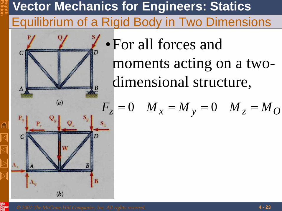
Equilibrium of a Rigid Body in Two Dimensions
•For all forces and
moments acting on a two-
dimensional structure,
Ozyxz MMMMF 00
© 2007 The McGraw-Hill Companies, Inc. All rights reserved.
Vector Mechanics for Engineers: Statics
Eig
hth
E
ditio
n
4 - 24
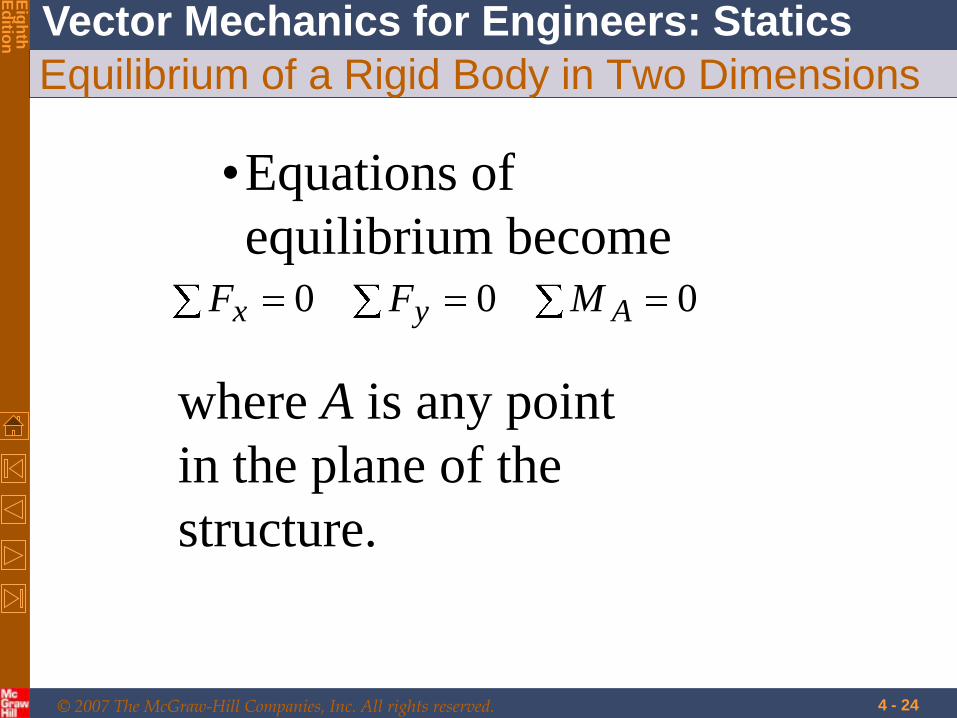
Equilibrium of a Rigid Body in Two Dimensions
•Equations of
equilibrium become 000 Ayx MFF
where A is any point
in the plane of the
structure.

© 2007 The McGraw-Hill Companies, Inc. All rights reserved.
Vector Mechanics for Engineers: Statics
Eig
hth
E
ditio
n
Alternative form of equilibrium equations
4 - 25

© 2007 The McGraw-Hill Companies, Inc. All rights reserved.
Vector Mechanics for Engineers: Statics
Eig
hth
E
ditio
n
Alternative form of equilibrium equations
4 - 26
If MA = 0, then R must pass through A
If Fx = 0 where x is arbitrary then R not
only passes through A but is also
perpendicular to x
If MB = 0 where B is any point such that
AB is not perpendicular to x direction
then R = 0

© 2007 The McGraw-Hill Companies, Inc. All rights reserved.
Vector Mechanics for Engineers: Statics
Eig
hth
E
ditio
n
Alternative form of equilibrium equations
4 - 27
© 2007 The McGraw-Hill Companies, Inc. All rights reserved.
Vector Mechanics for Engineers: Statics
Eig
hth
E
ditio
n
4 - 28
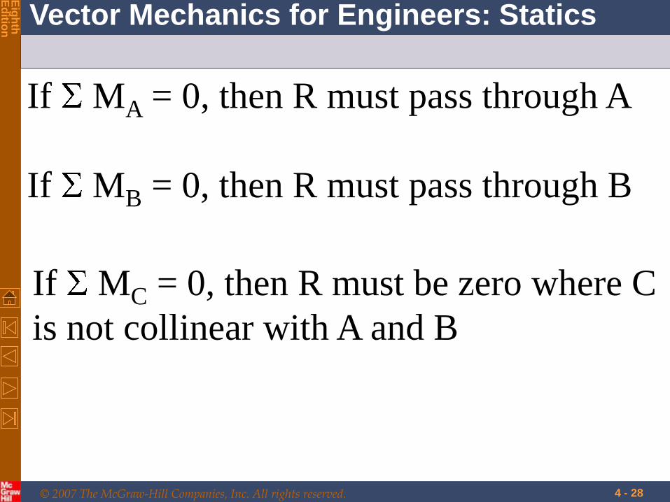
If MA = 0, then R must pass through A
If MB = 0, then R must pass through B
If MC = 0, then R must be zero where C
is not collinear with A and B

© 2007 The McGraw-Hill Companies, Inc. All rights reserved.
Vector Mechanics for Engineers: Statics
Eig
hth
E
ditio
n
The 3 equations can be solved for no more than 3 unknowns.
The 3 equations can not be augmented with additional equations, but they can be replaced
0
0
0
B
A
x
M
M
F
0
0
0
C
B
A
M
M
M

© 2007 The McGraw-Hill Companies, Inc. All rights reserved.
Vector Mechanics for Engineers: Statics
Eig
hth
E
ditio
n
Statically Indeterminate Reactions
•More unknowns than equations
Four unknown reaction force unknown, three equations available

© 2007 The McGraw-Hill Companies, Inc. All rights reserved.
Vector Mechanics for Engineers: Statics
Eig
hth
E
ditio
n
•Fewer unknowns than equations, partially constrained
Two unknown reaction force unknown, three equations available
Partially Constrained, or referred as unstable
© 2007 The McGraw-Hill Companies, Inc. All rights reserved.
Vector Mechanics for Engineers: Statics
Eig
hth
E
ditio
n
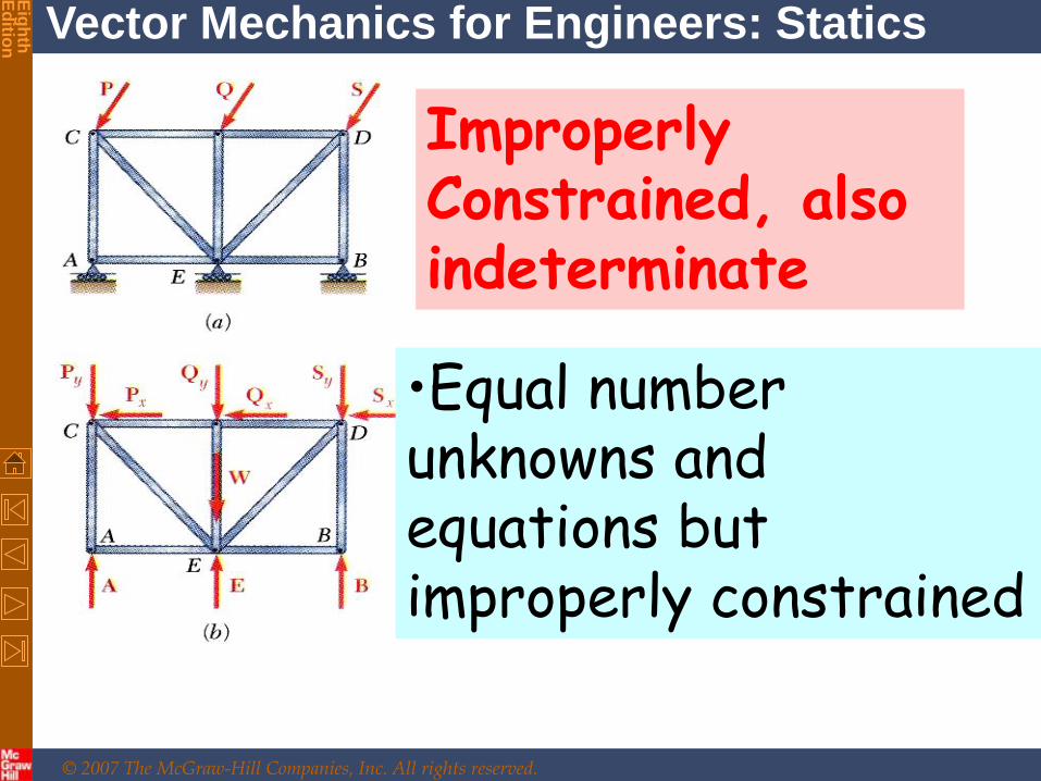
•Equal number unknowns and equations but improperly constrained
Improperly Constrained, also indeterminate

© 2007 The McGraw-Hill Companies, Inc. All rights reserved.
Vector Mechanics for Engineers: Statics
Eig
hth
E
ditio
n
Free to move horizontally
Fx=0, then two equation left for three unknowns

© 2007 The McGraw-Hill Companies, Inc. All rights reserved.
Vector Mechanics for Engineers: Statics
Eig
hth
E
ditio
n
4 - 34
If the reactions are
concurrent or parallel,
the structure is
improperly constrained.
Improperly Constrained, also indeterminate
AM 0
© 2007 The McGraw-Hill Companies, Inc. All rights reserved.
Vector Mechanics for Engineers: Statics
Eig
hth
E
ditio
n
4 - 35

© 2007 The McGraw-Hill Companies, Inc. All rights reserved.
Vector Mechanics for Engineers: Statics
Eig
hth
E
ditio
n
4 - 36
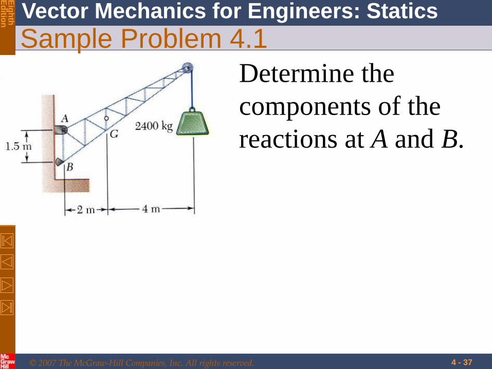
Sample Problem 4.1
It is held in place by a
pin at A and a rocker
at B. The center of
gravity of the crane is
located at G.
A fixed crane has a
mass of 1000 kg
and is used to lift a
2400 kg crate.
© 2007 The McGraw-Hill Companies, Inc. All rights reserved.
Vector Mechanics for Engineers: Statics
Eig
hth
E
ditio
n
4 - 37
Sample Problem 4.1
Determine the
components of the
reactions at A and B.

© 2007 The McGraw-Hill Companies, Inc. All rights reserved.
Vector Mechanics for Engineers: Statics
Eig
hth
E
ditio
n
4 - 38
Sample Problem 4.1
SOLUTION:
•Create a free-body
diagram for the
crane.
•Determine reactions
at B and A.

© 2007 The McGraw-Hill Companies, Inc. All rights reserved.
Vector Mechanics for Engineers: Statics
Eig
hth
E
ditio
n
4 - 39
Sample Problem 4.1
•Free-body
diagram.
© 2007 The McGraw-Hill Companies, Inc. All rights reserved.
Vector Mechanics for Engineers: Statics
Eig
hth
E
ditio
n
4 - 40
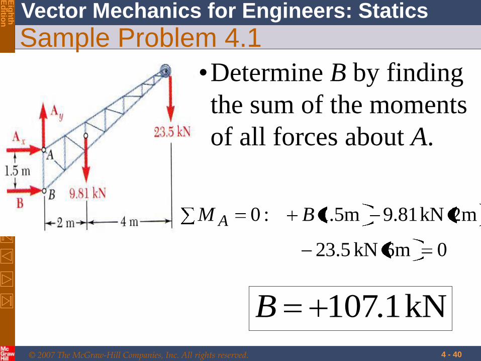
Sample Problem 4.1
•Determine B by finding
the sum of the moments
of all forces about A.
0m6kN5.23
m2kN81.9m5.1:0 BM A
kN1.107B

© 2007 The McGraw-Hill Companies, Inc. All rights reserved.
Vector Mechanics for Engineers: Statics
Eig
hth
E
ditio
n
4 - 41
Sample Problem 4.1
•Determine the reactions at
A by sum of all horizontal
forces and all vertical
forces. 0:0 BAF xx
kN1.107xA
0kN5.23kN81.9:0 yy AF
kN 3.33yA
© 2007 The McGraw-Hill Companies, Inc. All rights reserved.
Vector Mechanics for Engineers: Statics
Eig
hth
E
ditio
n

© 2007 The McGraw-Hill Companies, Inc. All rights reserved.
Vector Mechanics for Engineers: Statics
Eig
hth
E
ditio
n

© 2007 The McGraw-Hill Companies, Inc. All rights reserved.
Vector Mechanics for Engineers: Statics
Eig
hth
E
ditio
n

© 2007 The McGraw-Hill Companies, Inc. All rights reserved.
Vector Mechanics for Engineers: Statics
Eig
hth
E
ditio
n

© 2007 The McGraw-Hill Companies, Inc. All rights reserved.
Vector Mechanics for Engineers: Statics
Eig
hth
E
ditio
n

© 2007 The McGraw-Hill Companies, Inc. All rights reserved.
Vector Mechanics for Engineers: Statics
Eig
hth
E
ditio
n
4 - 47
© 2007 The McGraw-Hill Companies, Inc. All rights reserved.
Vector Mechanics for Engineers: Statics
Eig
hth
E
ditio
n
4 - 48
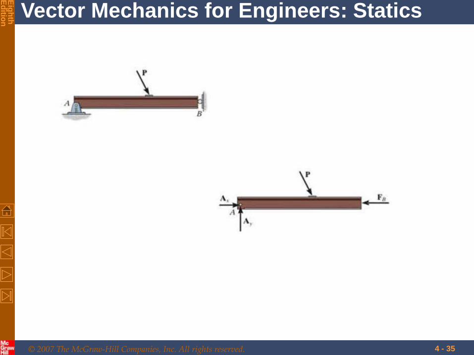
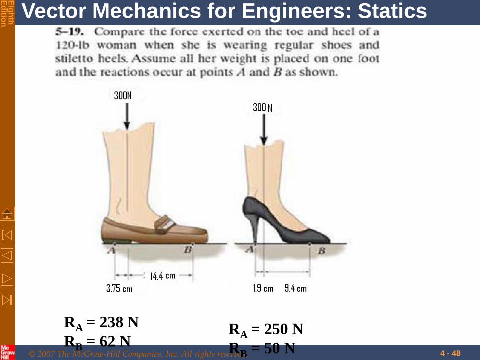
RA = 238 N
RB = 62 N RA = 250 N
RB = 50 N

© 2007 The McGraw-Hill Companies, Inc. All rights reserved.
Vector Mechanics for Engineers: Statics
Eig
hth
E
ditio
n
4 - 49

© 2007 The McGraw-Hill Companies, Inc. All rights reserved.
Vector Mechanics for Engineers: Statics
Eig
hth
E
ditio
n
4 - 50
© 2007 The McGraw-Hill Companies, Inc. All rights reserved.
Vector Mechanics for Engineers: Statics
Eig
hth
E
ditio
n
4 - 51

© 2007 The McGraw-Hill Companies, Inc. All rights reserved.
Vector Mechanics for Engineers: Statics
Eig
hth
E
ditio
n
4 - 52
Sample Problem 4.3 Determine the tension
in the cable and the
reaction at each pair
of wheels.

© 2007 The McGraw-Hill Companies, Inc. All rights reserved.
Vector Mechanics for Engineers: Statics
Eig
hth
E
ditio
n
4 - 53
Sample Problem 4.3
and its load is 5500 N,
and it is applied at G.
The cart is held in
position by the cable.
A loading car is at
rest on an inclined
track. The gross
weight of the car

© 2007 The McGraw-Hill Companies, Inc. All rights reserved.
Vector Mechanics for Engineers: Statics
Eig
hth
E
ditio
n
4 - 54
Sample Problem 4.3
SOLUTION:
•Create a free-body diagram
for the car with the
coordinate system aligned
with the track.

© 2007 The McGraw-Hill Companies, Inc. All rights reserved.
Vector Mechanics for Engineers: Statics
Eig
hth
E
ditio
n
4 - 55
Sample Problem 4.3
•Determine the cable
tension by summing force
components parallel to the
track.
•Determine the reactions at
the wheels by summing
moments about points
above each axle.

© 2007 The McGraw-Hill Companies, Inc. All rights reserved.
Vector Mechanics for Engineers: Statics
Eig
hth
E
ditio
n
4 - 56
Sample Problem 4.3
• Create a free-body diagram
N 2320
25sinN 5500
N 4980
25cosN 5500
y
x
W
W

© 2007 The McGraw-Hill Companies, Inc. All rights reserved.
Vector Mechanics for Engineers: Statics
Eig
hth
E
ditio
n
4 - 57
Sample Problem 4.3
• Determine the reactions at the wheels.
0250mm1
mm150N 9804mm625N 2320:0
2R
M A
N 17582R
00mm125
mm150N 9804mm625N 2320:0
1R
M B
.4N 5621R
• Determine the cable tension.
0TN 4980:0xF
N 4980T

© 2007 The McGraw-Hill Companies, Inc. All rights reserved.
Vector Mechanics for Engineers: Statics
Eig
hth
E
ditio
n
4 - 58
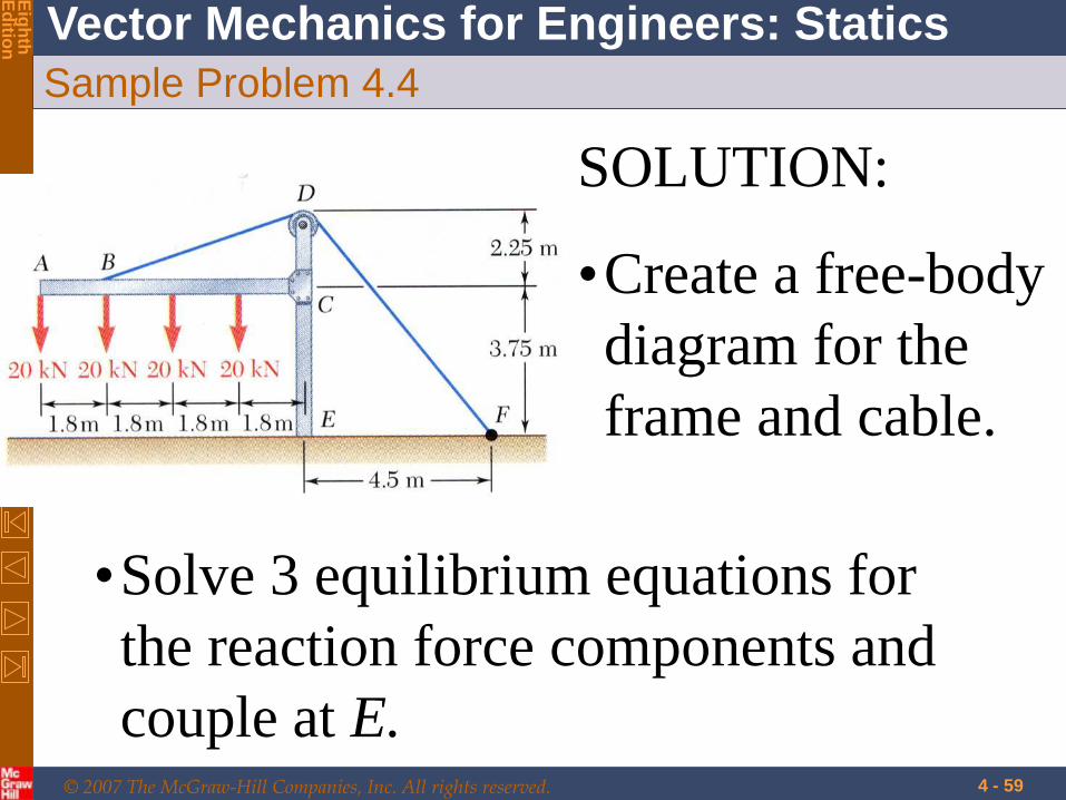
Sample Problem 4.4
The frame supports
part of the roof of a
small building. The
tension in the cable
is 150 kN.
Determine the
reaction at the fixed
end E.
© 2007 The McGraw-Hill Companies, Inc. All rights reserved.
Vector Mechanics for Engineers: Statics
Eig
hth
E
ditio
n
4 - 59
Sample Problem 4.4
SOLUTION:
•Create a free-body
diagram for the
frame and cable.
•Solve 3 equilibrium equations for
the reaction force components and
couple at E.

© 2007 The McGraw-Hill Companies, Inc. All rights reserved.
Vector Mechanics for Engineers: Statics
Eig
hth
E
ditio
n
4 - 60
Sample Problem 4.4
• Create a free-body diagram for the
frame and cable.

© 2007 The McGraw-Hill Companies, Inc. All rights reserved.
Vector Mechanics for Engineers: Statics
Eig
hth
E
ditio
n
4 - 61
Sample Problem 4.4
• Solve 3 equilibrium equations for the
reaction force components and couple.
0kN1505.7
5.4:0 xx EF
kN 0.90xE
0kN1505.7
6kN204:0 yy EF
kN 200yE
:0EM
0m5.4kN1505.7
6
m8.1kN20m6.3kN20
m4.5kN20m7.2kN20
EM
mkN0.180EM

© 2007 The McGraw-Hill Companies, Inc. All rights reserved.
Vector Mechanics for Engineers: Statics
Eig
hth
E
ditio
n
4 - 62
Draw the free body diagram of the foot
lever shown in Figure. The operator
applies a vertical force to the pedal so
that the spring is stretched 1.5 in. and
the force in the short link at B is 20 lb.

© 2007 The McGraw-Hill Companies, Inc. All rights reserved.
Vector Mechanics for Engineers: Statics
Eig
hth
E
ditio
n
4 - 63
Two smooth pipes, each having a mass
of 300 kg. are supported by the fork of
the tractor in Fig. Draw the free body
diagrams
for each pipe and both pipes together.

© 2007 The McGraw-Hill Companies, Inc. All rights reserved.
Vector Mechanics for Engineers: Statics
Eig
hth
E
ditio
n
4 - 64
Equilibrium of a Two-Force Body
•Consider a plate subjected
to two forces F1 and F2
•For static equilibrium, the
sum of moments about A
must be zero. The
moment of F2 must be
zero. It follows that the
line of action of F2 must
pass through A.

© 2007 The McGraw-Hill Companies, Inc. All rights reserved.
Vector Mechanics for Engineers: Statics
Eig
hth
E
ditio
n
4 - 65
Equilibrium of a Two-Force Body
•Similarly, the line of action
of F1 must pass through B
for the sum of moments
about B to be zero.

© 2007 The McGraw-Hill Companies, Inc. All rights reserved.
Vector Mechanics for Engineers: Statics
Eig
hth
E
ditio
n
4 - 66
Equilibrium of a Two-Force Body
•Requiring that the sum of
forces in any direction be
zero leads to the conclusion
that F1 and F2 must have
equal magnitude but
opposite sense.

© 2007 The McGraw-Hill Companies, Inc. All rights reserved.
Vector Mechanics for Engineers: Statics
Eig
hth
E
ditio
n
Two and Three force members
4 - 67
Find reactions at
A, B, D.

© 2007 The McGraw-Hill Companies, Inc. All rights reserved.
Vector Mechanics for Engineers: Statics
Eig
hth
E
ditio
n
Two and Three force members
4 - 68

© 2007 The McGraw-Hill Companies, Inc. All rights reserved.
Vector Mechanics for Engineers: Statics
Eig
hth
E
ditio
n

© 2007 The McGraw-Hill Companies, Inc. All rights reserved.
Vector Mechanics for Engineers: Statics
Eig
hth
E
ditio
n

© 2007 The McGraw-Hill Companies, Inc. All rights reserved.
Vector Mechanics for Engineers: Statics
Eig
hth
E
ditio
n

© 2007 The McGraw-Hill Companies, Inc. All rights reserved.
Vector Mechanics for Engineers: Statics
Eig
hth
E
ditio
n

© 2007 The McGraw-Hill Companies, Inc. All rights reserved.
Vector Mechanics for Engineers: Statics
Eig
hth
E
ditio
n
© 2007 The McGraw-Hill Companies, Inc. All rights reserved.
Vector Mechanics for Engineers: Statics
Eig
hth
E
ditio
n
4 - 74

© 2007 The McGraw-Hill Companies, Inc. All rights reserved.
Vector Mechanics for Engineers: Statics
Eig
hth
E
ditio
n
Two force member
4 - 75
The bucket link AB on the back hoe is
a typical example of a two-force
member since it is pin connected at its
ends and provided its weight is
neglected no other force acts on this
member.

© 2007 The McGraw-Hill Companies, Inc. All rights reserved.
Vector Mechanics for Engineers: Statics
Eig
hth
E
ditio
n
4 - 76
Equilibrium of a Three-Force Body
•Consider a rigid body
subjected to forces acting
at only 3 points.
•Assuming that their lines of
action intersect, the
moment of F1 and F2
about the point of
intersection represented by
D is zero.

© 2007 The McGraw-Hill Companies, Inc. All rights reserved.
Vector Mechanics for Engineers: Statics
Eig
hth
E
ditio
n
4 - 77
Equilibrium of a Three-Force Body
•Since the rigid body is in
equilibrium, the sum of the
moments of F1, F2, and F3
about any axis must be zero.
•The moment of F3 about D
must be zero as well and that
the line of action of F3 must
pass through D.

© 2007 The McGraw-Hill Companies, Inc. All rights reserved.
Vector Mechanics for Engineers: Statics
Eig
hth
E
ditio
n
4 - 78
Equilibrium of a Three-Force Body
•The lines of action of the
three forces must be
concurrent or parallel.

© 2007 The McGraw-Hill Companies, Inc. All rights reserved.
Vector Mechanics for Engineers: Statics
Eig
hth
E
ditio
n
4 - 79
Sample Problem 4.6
A man raises a 10 kg joist, of length
4 m, by pulling on a rope.
Find the tension in the rope and the
reaction at A.

© 2007 The McGraw-Hill Companies, Inc. All rights reserved.
Vector Mechanics for Engineers: Statics
Eig
hth
E
ditio
n
4 - 80
Sample Problem 4.6 •The three forces must
be concurrent for
static equilibrium.
•Reaction R passes
through the
intersection of the
lines of action of the
weight and rope
forces.

© 2007 The McGraw-Hill Companies, Inc. All rights reserved.
Vector Mechanics for Engineers: Statics
Eig
hth
E
ditio
n
4 - 81
•Determine the direction of
R.
636.1414.1
313.2tan
m 2.313m 515.0828.2
m 515.020tanm 414.1)2045cot(
m 414.1
m828.245cosm445cos
21
AE
CE
BDBFCE
CDBD
AFAECD
ABAF
6.58

© 2007 The McGraw-Hill Companies, Inc. All rights reserved.
Vector Mechanics for Engineers: Statics
Eig
hth
E
ditio
n
4 - 82
Sample Problem 4.6
•Determine the
magnitude of the
reaction force R.
38.6sin
N 1.98
110sin4.31sin
RT
N 8.147
N9.81
R
T

© 2007 The McGraw-Hill Companies, Inc. All rights reserved.
Vector Mechanics for Engineers: Statics
Eig
hth
E
ditio
n
4 - 83
Equilibrium of a Rigid Body in Three Dimensions
•Six scalar equations are required to
express the conditions for the
equilibrium of a rigid body in the general
three dimensional case.
000
000
zyx
zyx
MMM
FFF
© 2007 The McGraw-Hill Companies, Inc. All rights reserved.
Vector Mechanics for Engineers: Statics
Eig
hth
E
ditio
n
4 - 84
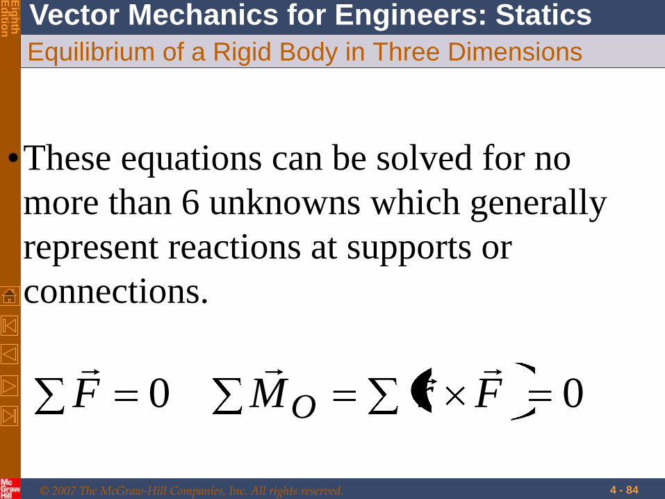
Equilibrium of a Rigid Body in Three Dimensions
•These equations can be solved for no
more than 6 unknowns which generally
represent reactions at supports or
connections.
00 FrMF O

© 2007 The McGraw-Hill Companies, Inc. All rights reserved.
Vector Mechanics for Engineers: Statics
Eig
hth
E
ditio
n
4 - 85
Reactions at Supports and Connections for a Three-
Dimensional Structure

© 2007 The McGraw-Hill Companies, Inc. All rights reserved.
Vector Mechanics for Engineers: Statics
Eig
hth
E
ditio
n
4 - 86

© 2007 The McGraw-Hill Companies, Inc. All rights reserved.
Vector Mechanics for Engineers: Statics
Eig
hth
E
ditio
n
4 - 87

© 2007 The McGraw-Hill Companies, Inc. All rights reserved.
Vector Mechanics for Engineers: Statics
Eig
hth
E
ditio
n
4 - 88

© 2007 The McGraw-Hill Companies, Inc. All rights reserved.
Vector Mechanics for Engineers: Statics
Eig
hth
E
ditio
n
4 - 89
Reactions at Supports and Connections for a Three-
Dimensional Structure

© 2007 The McGraw-Hill Companies, Inc. All rights reserved.
Vector Mechanics for Engineers: Statics
Eig
hth
E
ditio
n
Universal Joints

© 2007 The McGraw-Hill Companies, Inc. All rights reserved.
Vector Mechanics for Engineers: Statics
Eig
hth
E
ditio
n
4 - 91
Reactions at Supports and Connections for a Three-
Dimensional Structure

© 2007 The McGraw-Hill Companies, Inc. All rights reserved.
Vector Mechanics for Engineers: Statics
Eig
hth
E
ditio
n
4 - 92

© 2007 The McGraw-Hill Companies, Inc. All rights reserved.
Vector Mechanics for Engineers: Statics
Eig
hth
E
ditio
n
4 - 93

© 2007 The McGraw-Hill Companies, Inc. All rights reserved.
Vector Mechanics for Engineers: Statics
Eig
hth
E
ditio
n
Sample problem 4.7
• A 20-kg ladder used to reach
high shelves in a storeroom is
supported by two flanged
wheels A and B mounted on a
rail and by an unflanged wheel
C resting against a rail fixed to
the wall. An 80-kg man stands
on the ladder and leans to the
right. The line of action of the
combined weight W of the man
and ladder intersects the floor at
point D. Determine the
reactions at A, B, and C.

© 2007 The McGraw-Hill Companies, Inc. All rights reserved.
Vector Mechanics for Engineers: Statics
Eig
hth
E
ditio
n
4 - 95

© 2007 The McGraw-Hill Companies, Inc. All rights reserved.
Vector Mechanics for Engineers: Statics
Eig
hth
E
ditio
n
(80 20)(9.81) 981
0
981 0
981 0
0
y z y z
y y
z z
W mgj j j
F
A j A k B j B k j Ck
A B
A B C
© 2007 The McGraw-Hill Companies, Inc. All rights reserved.
Vector Mechanics for Engineers: Statics
Eig
hth
E
ditio
n
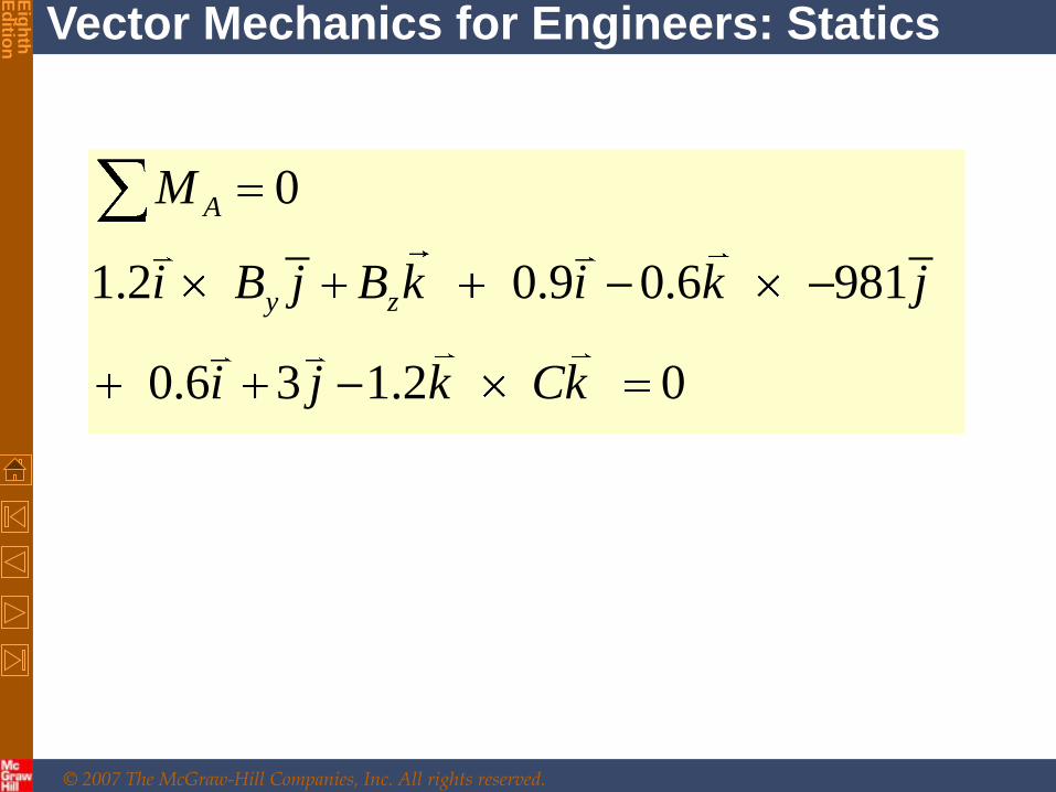
0
1.2 0.9 0.6 981
0.6 3 1.2 0
A
y z
M
i B j B k i k j
i j k Ck

© 2007 The McGraw-Hill Companies, Inc. All rights reserved.
Vector Mechanics for Engineers: Statics
Eig
hth
E
ditio
n
02.136.0
9816.09.02.1
0
0
0981
981)81.9)(2080(
kCkji
jkikBjBi
M
CBA
BA
jjjmgW
zy
A
zz
yy
5 unknowns and 5 equations,
so the problem can be solved

© 2007 The McGraw-Hill Companies, Inc. All rights reserved.
Vector Mechanics for Engineers: Statics
Eig
hth
E
ditio
n
4 - 99
Sample Problem 4.8 A sign of uniform density weighs 540 N
and is supported by a ball-and-socket joint
at A and by two cables.
Determine the tension in each cable and the
reaction at A.

© 2007 The McGraw-Hill Companies, Inc. All rights reserved.
Vector Mechanics for Engineers: Statics
Eig
hth
E
ditio
n
4 - 100
Sample Problem 4.8

© 2007 The McGraw-Hill Companies, Inc. All rights reserved.
Vector Mechanics for Engineers: Statics
Eig
hth
E
ditio
n
4 - 101
Sample Problem 4.8
SOLUTION:
•Create a free-body
diagram.
•Apply static
equilibrium to
develop equations
for the unknown
reactions.

© 2007 The McGraw-Hill Companies, Inc. All rights reserved.
Vector Mechanics for Engineers: Statics
Eig
hth
E
ditio
n
4 - 102
Sample Problem 4.8

© 2007 The McGraw-Hill Companies, Inc. All rights reserved.
Vector Mechanics for Engineers: Statics
Eig
hth
E
ditio
n
4 - 103
Sample Problem 4.8
Since there are only 5 unknowns, the
sign is partially constrain. It is free to
rotate about the x axis. It is, however, in
equilibrium for the given loading.

© 2007 The McGraw-Hill Companies, Inc. All rights reserved.
Vector Mechanics for Engineers: Statics
Eig
hth
E
ditio
n
4 - 104
Sample Problem 4.8
kjiT
kjiT
rr
rrTT
kjiT
kjiT
rr
rrTT
EC
EC
EC
ECECEC
BD
BD
BD
BDBDBD
72
73
76
32
31
32
7
236
12
848

© 2007 The McGraw-Hill Companies, Inc. All rights reserved.
Vector Mechanics for Engineers: Statics
Eig
hth
E
ditio
n
4 - 105
Sample Problem 4.
623 7
313 7
2 23 7
540N 0
: 0
: 270 N 0
: 0
1.2 m 540N 0
: 1.6 0.5143 0
: .8 .771 648 N 0
BD EC
x BD EC
y BD EC
z BD EC
A B BD E EC
BD EC
BD EC
F A T T j
i A T T
j A T T
k A T T
M r T r T i j
j T T
k T T

© 2007 The McGraw-Hill Companies, Inc. All rights reserved.
Vector Mechanics for Engineers: Statics
Eig
hth
E
ditio
n
4 - 106
Sample Problem 4.
623 7
313 7
2 23 7
: 0
: 270 N 0
: 0
: 1.6 0.5143 0
: .8 .771 648 N 0
x BD EC
y BD EC
z BD EC
BD EC
BD EC
i A T T
j A T T
k A T T
j T T
k T T

© 2007 The McGraw-Hill Companies, Inc. All rights reserved.
Vector Mechanics for Engineers: Statics
Eig
hth
E
ditio
n
4 - 107
Sample Problem 4.
kjiA
TT ECBD
N 45.02N 202.3N 675.3
N 3.630N 6.202
Solve the 5 equations
for the 5 unknowns,

© 2007 The McGraw-Hill Companies, Inc. All rights reserved.
Vector Mechanics for Engineers: Statics
Eig
hth
E
ditio
n
What if…?
4 - 108
Can the sign be in static
equilibrium if cable BD
is removed?

© 2007 The McGraw-Hill Companies, Inc. All rights reserved.
Vector Mechanics for Engineers: Statics
Eig
hth
E
ditio
n
4 - 109
The sign cannot be in static equilibrium
because TEC causes a moment about the y-
axis (due to the existence of TEC,Z) which
must be countered by an equal and
opposite moment.
This can only be provided by a cable
tension that has a z-component in the
negative-z direction, such as what TBD
has.

© 2004 The McGraw-Hill Companies, Inc. All rights reserved.
Se
ve
nth
E
ditio
n
Sample Problem 4.9
• A uniform pipe cover of radius r = 240 mm and mass 30 kg is held in a horizontal position by the cable CD. Assuming that the bearing at B does not exert any axial thrust, determine the tension in the cable and the reactions at A and B.

© 2004 The McGraw-Hill Companies, Inc. All rights reserved.
Se
ve
nth
E
ditio
n
The supports do
not exert an
appreciable
couple during
normal operation
and these are not
included in
analysis.

© 2004 The McGraw-Hill Companies, Inc. All rights reserved.
Se
ve
nth
E
ditio
n
0294
7
2
7
3
7
622
0
07
2
2947
3
7
6
0294
0
kkrir
kTjTiTkrirkAjAiAkr
M
kTA
jTBAiTBA
jTjBiBkAjAiA
F
zyx
B
z
yyxx
yxzyx
6 unknowns and 6 equations

© 2004 The McGraw-Hill Companies, Inc. All rights reserved.
Se
ve
nth
E
ditio
n
Sample Problem 4.10

© 2004 The McGraw-Hill Companies, Inc. All rights reserved.
Se
ve
nth
E
ditio
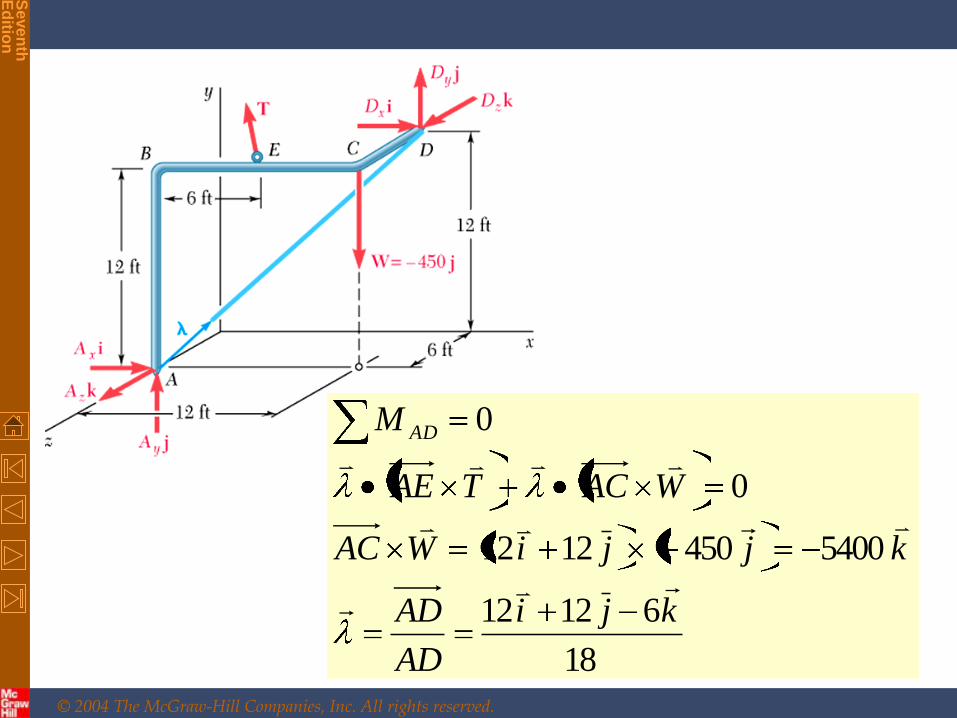
n • A 450-lb load hangs from the comer C of a rigid piece of pipe ABCD which has been bent as shown. The pipe is supported by the ball-and-socket joints A and D, which are fastened, respectively, to the floor and to a vertical wall, and by a cable attached at the midpoint E of the portion BC of the pipe and at a point G on the wall. Determine (a) where G should be located if the tension in the cable is to be minimum, (b) the corresponding minimum value of the tension.

© 2004 The McGraw-Hill Companies, Inc. All rights reserved.
Se
ve
nth
E
ditio
n
© 2004 The McGraw-Hill Companies, Inc. All rights reserved.
Se
ve
nth
E
ditio
n
18
61212
54004501212
0
0
kji
AD
AD
kjjiWAC
WACTAE
M AD

© 2004 The McGraw-Hill Companies, Inc. All rights reserved.
Se
ve
nth
E
ditio
n
12 12 65400 1800
18
4 2 4
4 2 4
6
4 2 4 12 12 6
6 18
i j kAE T k
AE T T AE
AE i j k
i j kunit vector along AE
T must be along this unit vector
i j k i j kT
min
6 12 1800
6 1800
200 100 200
i j
T
T i j k

© 2004 The McGraw-Hill Companies, Inc. All rights reserved.
Se
ve
nth
E
ditio
n
Must be
the same
direction x=0, y=15 ft
6 ( 12) 0 6
6 12 0 6
200 100 200
,
EG x i y j k
x y
x y are the coordinates of G