eighth edition - apl100apl100.wdfiles.com/local--files/notes/friction revised.pdf · eighth edition...
TRANSCRIPT

VECTOR MECHANICS FOR ENGINEERS:
STATICS
Eighth Edition
Ferdinand P. Beer
E. Russell Johnston, Jr.
Lecture Notes:
J. Walt Oler
Texas Tech University
CHAPTER
© 2007 The McGraw-Hill Companies, Inc. All rights reserved.
8 Friction

© 2007 The McGraw-Hill Companies, Inc. All rights reserved.
Vector Mechanics for Engineers: Statics
Eig
hth
E
ditio
n
8 - 2
Contents
Introduction
Laws of Dry Friction. Coefficients
of Friction.
Angles of Friction
Problems Involving Dry Friction
Sample Problem 8.1
Sample Problem 8.3
Wedges
Square-Threaded Screws
Sample Problem 8.5
Journal Bearings. Axle Friction.
Thrust Bearings. Disk Friction.
Wheel Friction. Rolling Resistance.
Sample Problem 8.6
Belt Friction.
Sample Problem 8.8

© 2007 The McGraw-Hill Companies, Inc. All rights reserved.
Vector Mechanics for Engineers: Statics
Eig
hth
E
ditio
n
8 - 3
Introduction
• In preceding chapters, it was assumed that
surfaces in contact were either frictionless
(surfaces could move freely with respect to
each other) or rough (tangential forces
prevent relative motion between surfaces).

© 2007 The McGraw-Hill Companies, Inc. All rights reserved.
Vector Mechanics for Engineers: Statics
Eig
hth
E
ditio
n
8 - 4
Introduction
• Actually, no perfectly frictionless surface
exists. For two surfaces in contact,
tangential forces, called friction forces, will
develop if one attempts to move one relative
to the other.

© 2007 The McGraw-Hill Companies, Inc. All rights reserved.
Vector Mechanics for Engineers: Statics
Eig
hth
E
ditio
n
8 - 5
Introduction
• However, the friction forces are limited in
magnitude and will not prevent motion if
sufficiently large forces are applied.
• The distinction between frictionless and
rough is, therefore, a matter of degree.

© 2007 The McGraw-Hill Companies, Inc. All rights reserved.
Vector Mechanics for Engineers: Statics
Eig
hth
E
ditio
n
8 - 6
Introduction
• There are two types of friction: dry or
Coulomb friction and fluid friction. Fluid
friction applies to lubricated mechanisms.
• The present discussion is limited to dry
friction between non-lubricated surfaces.

© 2007 The McGraw-Hill Companies, Inc. All rights reserved.
Vector Mechanics for Engineers: Statics
Eig
hth
E
ditio
n
8 - 7
The Laws of Dry Friction. Coefficients of Friction
• Block of weight W placed on
horizontal surface. Forces acting on
block are its weight and reaction of
surface N.
• Small horizontal force P applied to
block. For block to remain stationary,
in equilibrium, a horizontal
component F of the surface reaction
is required. F is a static-friction
force.

© 2007 The McGraw-Hill Companies, Inc. All rights reserved.
Vector Mechanics for Engineers: Statics
Eig
hth
E
ditio
n
8 - 8
The Laws of Dry Friction. Coefficients of Friction
• As P increases, the static-friction
force F increases as well until it
reaches a maximum value Fm.
NF sm
• Further increase in P causes the block to
begin to move as F drops to a smaller
kinetic-friction force Fk.
NF kk

© 2007 The McGraw-Hill Companies, Inc. All rights reserved.
Vector Mechanics for Engineers: Statics
Eig
hth
E
ditio
n
8 - 9
The Laws of Dry Friction. Coefficients of Friction

© 2007 The McGraw-Hill Companies, Inc. All rights reserved.
Vector Mechanics for Engineers: Statics
Eig
hth
E
ditio
n
8 - 10
The Laws of Dry Friction. Coefficients of Friction

© 2007 The McGraw-Hill Companies, Inc. All rights reserved.
Vector Mechanics for Engineers: Statics
Eig
hth
E
ditio
n
8 - 11
The Laws of Dry Friction. Coefficients of Friction
• Maximum static-friction force:
NF sm
• Kinetic-friction force:
sk
kk NF
75.0
• Maximum static-friction force and kinetic-friction force
are:
- proportional to normal force
- dependent on type and condition of contact surfaces
- independent of contact area

© 2007 The McGraw-Hill Companies, Inc. All rights reserved.
Vector Mechanics for Engineers: Statics
Eig
hth
E
ditio
n
8 - 12
The Laws of Dry Friction. Coefficients of Friction
• Four situations can occur when a rigid body is in contact with a
horizontal surface:
• No friction,
(Px = 0)
• No motion,
(Px < Fm)

© 2007 The McGraw-Hill Companies, Inc. All rights reserved.
Vector Mechanics for Engineers: Statics
Eig
hth
E
ditio
n
8 - 13
The Laws of Dry Friction. Coefficients of Friction
• Four situations can occur when a rigid body is in contact with a
horizontal surface:
• Motion impending,
(Px = Fm)
• Motion,
(Px > Fm)
© 2007 The McGraw-Hill Companies, Inc. All rights reserved.
Vector Mechanics for Engineers: Statics
Eig
hth
E
ditio
n
8 - 14
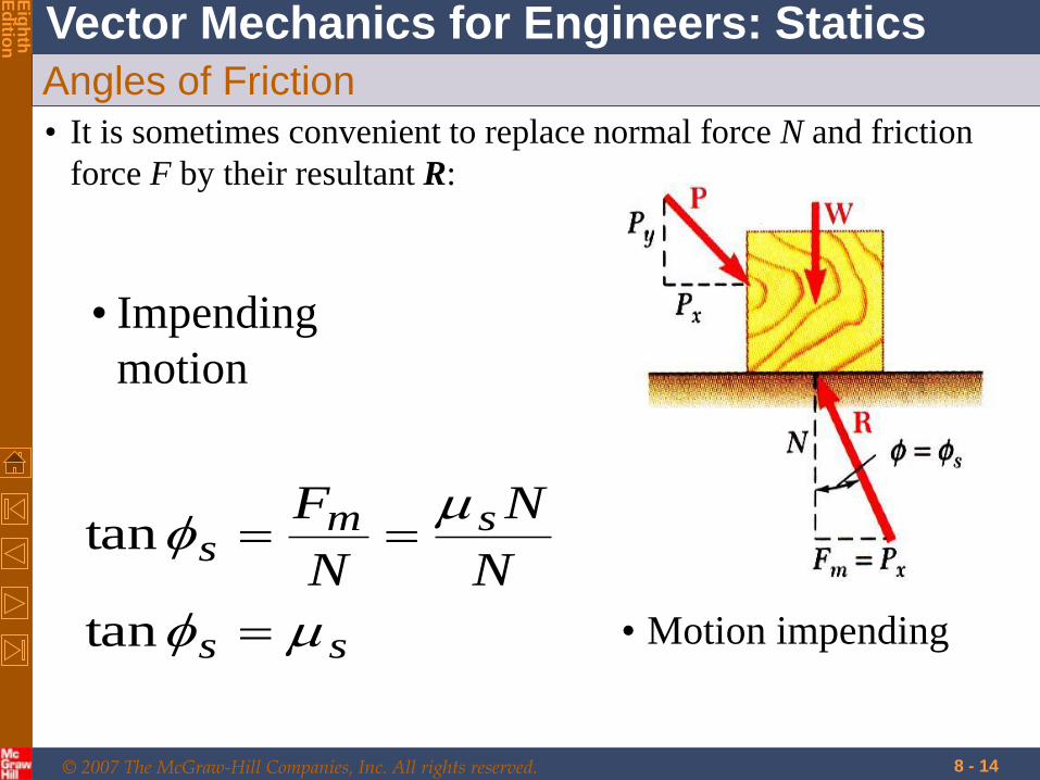
Angles of Friction
• It is sometimes convenient to replace normal force N and friction
force F by their resultant R:
• Impending
motion
ss
sms
N
N
N
F
tan
tan
• Motion impending

© 2007 The McGraw-Hill Companies, Inc. All rights reserved.
Vector Mechanics for Engineers: Statics
Eig
hth
E
ditio
n
8 - 15
Angles of Friction
• It is sometimes convenient to replace normal force N and friction
force F by their resultant R:
• Motion
kk
kkk
N
N
N
F
tan
tan

© 2007 The McGraw-Hill Companies, Inc. All rights reserved.
Vector Mechanics for Engineers: Statics
Eig
hth
E
ditio
n
8 - 16
Problems Involving Dry Friction
Impending motion at all points of contact
(body on verge of slipping)
No apparent Impending motion
Impending motion at some points of contact

© 2007 The McGraw-Hill Companies, Inc. All rights reserved.
Vector Mechanics for Engineers: Statics
Eig
hth
E
ditio
n
Impending Motion at All Points of Contact
8 - 17
Find the smallest angle q for which the 100 N
bar can be placed against the wall, without
slipping. (Five unknowns). Slipping occurs
simultaneously at A and B

© 2007 The McGraw-Hill Companies, Inc. All rights reserved.
Vector Mechanics for Engineers: Statics
Eig
hth
E
ditio
n
8 - 18
For a minute assume there was a roller at B. Then Na=mg and F
= (N-W/2)/tanq. F is large if theta is small. A limiting value will
reached. At larger theta F will be smaller than (mu NA) and will
not slip.

© 2007 The McGraw-Hill Companies, Inc. All rights reserved.
Vector Mechanics for Engineers: Statics
Eig
hth
E
ditio
n
8 - 19
Sample Problem 8.3
The moveable bracket shown
may be placed at any height
on the 3-cm diameter pipe.
If the coefficient of friction
between the pipe and bracket
is 0.25, determine the
minimum distance x at
which the load can be
supported. Neglect the
weight of the bracket.

© 2007 The McGraw-Hill Companies, Inc. All rights reserved.
Vector Mechanics for Engineers: Statics
Eig
hth
E
ditio
n
8 - 20
Sample Problem 8.3
The moveable bracket shown may be
placed at any height on the 3-cm
diameter pipe. If the coefficient of
friction between the pipe and bracket is
0.25, determine the minimum distance x
at which the load can be supported.
Neglect the weight of the bracket.

© 2007 The McGraw-Hill Companies, Inc. All rights reserved.
Vector Mechanics for Engineers: Statics
Eig
hth
E
ditio
n
8 - 21
Sample Problem 8.3

© 2007 The McGraw-Hill Companies, Inc. All rights reserved.
Vector Mechanics for Engineers: Statics
Eig
hth
E
ditio
n
8 - 22
SOLUTION:
•When W is placed at
minimum x, the bracket
is about to slip and
friction forces in upper
and lower collars are at
maximum value.
• Apply conditions for static equilibrium to find minimum x.

© 2007 The McGraw-Hill Companies, Inc. All rights reserved.
Vector Mechanics for Engineers: Statics
Eig
hth
E
ditio
n
8 - 23
SOLUTION:
• If x is larger than
minimum, by inspection
reactions NA and NB are
larger (moment due to W is
larger which tries to tilt the
bracket more creating larger
reactions). FA and FB do not
then reach their limiting
value. • Apply conditions for static equilibrium to find minimum x.

© 2007 The McGraw-Hill Companies, Inc. All rights reserved.
Vector Mechanics for Engineers: Statics
Eig
hth
E
ditio
n
8 - 24
When W is placed at minimum x, the
bracket is about to slip and friction forces
in upper and lower collars are at maximum
value.
BBsB
AAsA
NNF
NNF
25.0
25.0

© 2007 The McGraw-Hill Companies, Inc. All rights reserved.
Vector Mechanics for Engineers: Statics
Eig
hth
E
ditio
n
8 - 25
• Apply conditions for static equilibrium to find minimum x.
:0 xF 0 AB NNAB NN
:0 yF
WN
WNN
WFF
A
BA
BA
5.0
025.025.0
0
WNN BA 2

© 2007 The McGraw-Hill Companies, Inc. All rights reserved.
Vector Mechanics for Engineers: Statics
Eig
hth
E
ditio
n
8 - 26
:0 BM
05.1275.026
05.125.036
0cm5.1cm3cm6
xWWW
xWNN
xWFN
AA
AA
cm12x

© 2007 The McGraw-Hill Companies, Inc. All rights reserved.
Vector Mechanics for Engineers: Statics
Eig
hth
E
ditio
n
8 - 27
If x is larger, then slip will not occur at
any of the locations since Na is equal to
Nb and coeff. of friction is same.
Also, value of W does not matter. It
seems to decide the contact and friction is
related to reactions for slipping.

© 2007 The McGraw-Hill Companies, Inc. All rights reserved.
Vector Mechanics for Engineers: Statics
Eig
hth
E
ditio
n
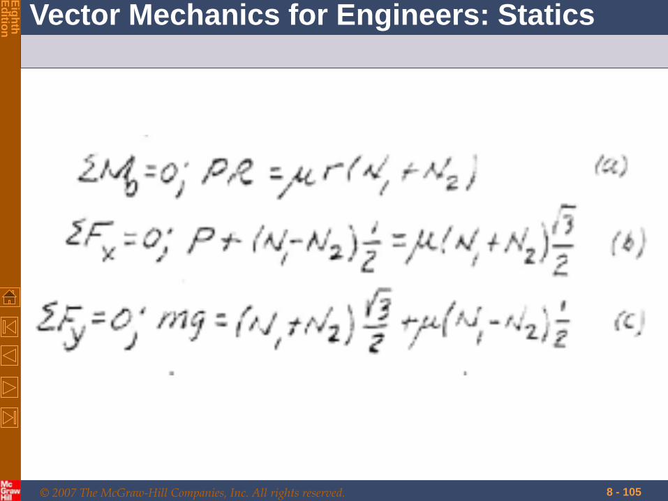
Fig. shows an automobile on a road inclined at
an angle q with the horizontal. s =0.6, d
=0.5.
What is the maximum inclination the car can
climb at uniform speed. The car is rear wheel
drive and has a loaded weight of 3600 lb (1 ib
=4.5 N).
Assume tires do not slip (and spin) i.e pure
rolling at point of contact.

© 2007 The McGraw-Hill Companies, Inc. All rights reserved.
Vector Mechanics for Engineers: Statics
Eig
hth
E
ditio
n

© 2007 The McGraw-Hill Companies, Inc. All rights reserved.
Vector Mechanics for Engineers: Statics
Eig
hth
E
ditio
n

© 2007 The McGraw-Hill Companies, Inc. All rights reserved.
Vector Mechanics for Engineers: Statics
Eig
hth
E
ditio
n

© 2007 The McGraw-Hill Companies, Inc. All rights reserved.
Vector Mechanics for Engineers: Statics
Eig
hth
E
ditio
n
•If drive wheel was allowed to slip we
replace s by d
8 - 32

© 2007 The McGraw-Hill Companies, Inc. All rights reserved.
Vector Mechanics for Engineers: Statics
Eig
hth
E
ditio
n
•Compute the torque needed by the drive
wheels to move the car at a uniform
speed up an incline where q =150. The
diameter of tire is 25 in. (1 inch =2.54
cm)

© 2007 The McGraw-Hill Companies, Inc. All rights reserved.
Vector Mechanics for Engineers: Statics
Eig
hth
E
ditio
n

© 2007 The McGraw-Hill Companies, Inc. All rights reserved.
Vector Mechanics for Engineers: Statics
Eig
hth
E
ditio
n

© 2007 The McGraw-Hill Companies, Inc. All rights reserved.
Vector Mechanics for Engineers: Statics
Eig
hth
E
ditio
n
No Apparent Impending Motion
8 - 36
Second type of problems: No Apparent
Impending Motion

© 2007 The McGraw-Hill Companies, Inc. All rights reserved.
Vector Mechanics for Engineers: Statics
Eig
hth
E
ditio
n
8 - 37
No apparent impending motion
6 unknowns, 6 equations

© 2007 The McGraw-Hill Companies, Inc. All rights reserved.
Vector Mechanics for Engineers: Statics
Eig
hth
E
ditio
n
It is not known whether motion is impending or not
8 - 38
• All applied forces known
• Coefficient of static friction is known
• Determine whether body will remain at rest or
slide

© 2007 The McGraw-Hill Companies, Inc. All rights reserved.
Vector Mechanics for Engineers: Statics
Eig
hth
E
ditio
n
Equilibrium Versus Frictional Equations
8 - 39

© 2007 The McGraw-Hill Companies, Inc. All rights reserved.
Vector Mechanics for Engineers: Statics
Eig
hth
E
ditio
n
Equilibrium Versus Frictional Equations
8 - 40
Problems where the friction force F is to
be an equilibrium force and satisfies the
inequality F < μsN then we can assume the
sense of direction of F on the free-body
diagram.
The correct sense is made known after
solving the equations of equilibrium for F.

© 2007 The McGraw-Hill Companies, Inc. All rights reserved.
Vector Mechanics for Engineers: Statics
Eig
hth
E
ditio
n
Equilibrium Versus Frictional Equations
8 - 41
This is possible because the equilibrium
equations equate to zero the components
of vector acting in the same direction.

© 2007 The McGraw-Hill Companies, Inc. All rights reserved.
Vector Mechanics for Engineers: Statics
Eig
hth
E
ditio
n
Equilibrium Versus Frictional Equations
8 - 42
However, in cases where the frictional
equation F = μsN is used in the solution of
a problem the convenience of assuming
the sense of F is lost.
Since the frictional equation relates only
the magnitude of two perpendicular
vectors. Consequently, F must always be
shown acting with its correct sense on the
free-body diagram.

© 2007 The McGraw-Hill Companies, Inc. All rights reserved.
Vector Mechanics for Engineers: Statics
Eig
hth
E
ditio
n
8 - 43
Sample Problem 8.1

© 2007 The McGraw-Hill Companies, Inc. All rights reserved.
Vector Mechanics for Engineers: Statics
Eig
hth
E
ditio
n
8 - 44
Sample Problem 8.1
A 100 N force acts as shown on a 300 N
block placed on an inclined plane. The
coefficients of friction between the block
and plane are s = 0.25 and k = 0.20.
Determine whether the block is in
equilibrium and find the value of the
friction force.

© 2007 The McGraw-Hill Companies, Inc. All rights reserved.
Vector Mechanics for Engineers: Statics
Eig
hth
E
ditio
n
8 - 45
•Determine values of friction force and
normal reaction force from plane required
to maintain equilibrium.
•Calculate maximum friction force and
compare with friction force required for
equilibrium. If it (maximum friction
force) is greater, block will not slide.

© 2007 The McGraw-Hill Companies, Inc. All rights reserved.
Vector Mechanics for Engineers: Statics
Eig
hth
E
ditio
n
8 - 46
•If maximum friction force is less than
friction force required for equilibrium,
block will slide. Calculate kinetic-
friction force.

© 2007 The McGraw-Hill Companies, Inc. All rights reserved.
Vector Mechanics for Engineers: Statics
Eig
hth
E
ditio
n
8 - 47
:0 xF
0N 300 - N 10053 F
N 80F
:0 yF
0N 300 - 54 N
N 240N

© 2007 The McGraw-Hill Companies, Inc. All rights reserved.
Vector Mechanics for Engineers: Statics
Eig
hth
E
ditio
n
8 - 48
•Calculate maximum friction force and
compare with friction force required
for equilibrium. If it is greater, block
will not slide.
m s mF N F 0.25 240 N 60 N
The block will slide down the plane.

© 2007 The McGraw-Hill Companies, Inc. All rights reserved.
Vector Mechanics for Engineers: Statics
Eig
hth
E
ditio
n
8 - 49

© 2007 The McGraw-Hill Companies, Inc. All rights reserved.
Vector Mechanics for Engineers: Statics
Eig
hth
E
ditio
n
8 - 50
Sample Problem 8.1
•If maximum friction force is less than
friction force required for equilibrium,
block will slide. Calculate kinetic-
friction force.
N 240200
N
.
FF kkactual
N 48actualF

© 2007 The McGraw-Hill Companies, Inc. All rights reserved.
Vector Mechanics for Engineers: Statics
Eig
hth
E
ditio
n
Impending Motion at Some Points of Contact
8 - 51
Determine the horizontal force P needed to
cause movement. Weight of each member is
100 N.

© 2007 The McGraw-Hill Companies, Inc. All rights reserved.
Vector Mechanics for Engineers: Statics
Eig
hth
E
ditio
n Impending Motion at Some Points of Contact
8 - 52
From the FBD 7 unknowns.
6 equilibrium equations and one static
friction equation

© 2007 The McGraw-Hill Companies, Inc. All rights reserved.
Vector Mechanics for Engineers: Statics
Eig
hth
E
ditio
n
Impending Motion at Some Points of Contact
8 - 53
As P increases it will either cause slipping
at A and no slipping at C, so that FA =
0.3NA and Fc ≤ 0.5Nc.
OR
slipping occurs at C and no slipping at
A, in which case Fc = 0.5Nc and FA ≤ 0.3NA
Calculate ‘P’ for each case and choose
the smaller P.

© 2007 The McGraw-Hill Companies, Inc. All rights reserved.
Vector Mechanics for Engineers: Statics
Eig
hth
E
ditio
n
8 - 54
Beam A B is subjected to a uniform load of 200 N/m and is
supported at B by post BC. If the coefficients of static
friction at B and C are μB = 0.2 and μC= 0.5. determine the
force P needed to pull the post out from under the beam.
Neglect the weight of the members and the thickness of the
beam.

© 2007 The McGraw-Hill Companies, Inc. All rights reserved.
Vector Mechanics for Engineers: Statics
Eig
hth
E
ditio
n
8 - 55
∑ MA=0 → NB = 400 N

© 2007 The McGraw-Hill Companies, Inc. All rights reserved.
Vector Mechanics for Engineers: Statics
Eig
hth
E
ditio
n
8 - 56

© 2007 The McGraw-Hill Companies, Inc. All rights reserved.
Vector Mechanics for Engineers: Statics
Eig
hth
E
ditio
n
8 - 57
4 unknowns. So assumption on
slipping.

© 2007 The McGraw-Hill Companies, Inc. All rights reserved.
Vector Mechanics for Engineers: Statics
Eig
hth
E
ditio
n
8 - 58
4 unknowns. So assumption on slipping.

© 2007 The McGraw-Hill Companies, Inc. All rights reserved.
Vector Mechanics for Engineers: Statics
Eig
hth
E
ditio
n
8 - 59

© 2007 The McGraw-Hill Companies, Inc. All rights reserved.
Vector Mechanics for Engineers: Statics
Eig
hth
E
ditio
n
8 - 60
Cylinder rolling from Assignment sheet

© 2007 The McGraw-Hill Companies, Inc. All rights reserved.
Vector Mechanics for Engineers: Statics
Eig
hth
E
ditio
n
8 - 61
Thrust Bearings. Disk Friction

© 2007 The McGraw-Hill Companies, Inc. All rights reserved.
Vector Mechanics for Engineers: Statics
Eig
hth
E
ditio
n Thrust bearings
Support the axial thrust of both horizontal as well as vertical shafts
Functions are to prevent the shaft from drifting in the axial direction and to transfer thrust loads applied on the shaft
Vertical thrust bearings also need to support the weight of the shaft and any components attached to it
The moving surface exerted against a thrust bearing may be the area of the end of the shaft or the area of a collar attached at any point to the shaft
Sorurce:web.iitd.ac.in/~rribeiro/MEL204170LubricationLec%20150211.ppt

© 2007 The McGraw-Hill Companies, Inc. All rights reserved.
Vector Mechanics for Engineers: Statics
Eig
hth
E
ditio
n Types of thrust bearings
Plain thrust: Consists of a stationary flat bearing surface against which the flat
end of a rotating shaft is permitted to bear
ROTOR
Bearing surface
Flat end of rotor
Axial movement
Sorurce:web.iitd.ac.in/~rribeiro/MEL204170LubricationLec%20150211.ppt

© 2007 The McGraw-Hill Companies, Inc. All rights reserved.
Vector Mechanics for Engineers: Statics
Eig
hth
E
ditio
n
8 - 64
Consider rotating hollow shaft:

© 2007 The McGraw-Hill Companies, Inc. All rights reserved.
Vector Mechanics for Engineers: Statics
Eig
hth
E
ditio
n
8 - 65
21
22 RR
APr
AA
PrNrFrM
k
kk

© 2007 The McGraw-Hill Companies, Inc. All rights reserved.
Vector Mechanics for Engineers: Statics
Eig
hth
E
ditio
n
8 - 66
Thrust Bearings. Disk Friction
For full circle of radius R,
PRM k32
21
22
31
32
32
2
0
2
21
22
2
1
RR
RRP
drdrRR
PM
k
R
R
k
q

© 2007 The McGraw-Hill Companies, Inc. All rights reserved.
Vector Mechanics for Engineers: Statics
Eig
hth
E
ditio
n
Clutch and friction
8 - 67
The largest torque which can be
transmitted by a clutch without
slipping

© 2007 The McGraw-Hill Companies, Inc. All rights reserved.
Vector Mechanics for Engineers: Statics
Eig
hth
E
ditio
n
8 - 68
Belt Friction

© 2007 The McGraw-Hill Companies, Inc. All rights reserved.
Vector Mechanics for Engineers: Statics
Eig
hth
E
ditio
n
8 - 69
The normal and frictional
forces, acting at different
points along the belt vary
both in magnitude and
direction.
Due to this unknown
distribution, the analysis of
the problem will first
require a study of forces
acting on a differential
element of the belt.
Belt Friction

© 2007 The McGraw-Hill Companies, Inc. All rights reserved.
Vector Mechanics for Engineers: Statics
Eig
hth
E
ditio
n
8 - 70

© 2007 The McGraw-Hill Companies, Inc. All rights reserved.
Vector Mechanics for Engineers: Statics
Eig
hth
E
ditio
n
8 - 71
Belt Friction
• Relate T1 and T2 when belt is about to slide to
right.

© 2007 The McGraw-Hill Companies, Inc. All rights reserved.
Vector Mechanics for Engineers: Statics
Eig
hth
E
ditio
n
8 - 72
Belt Friction
Draw free-body diagram for element of belt

© 2007 The McGraw-Hill Companies, Inc. All rights reserved.
Vector Mechanics for Engineers: Statics
Eig
hth
E
ditio
n
8 - 73
Belt Friction
02
cos2
cos:0
NTTTF sx qq
02
sin2
sin:0
TTTNFy

© 2007 The McGraw-Hill Companies, Inc. All rights reserved.
Vector Mechanics for Engineers: Statics
Eig
hth
E
ditio
n
8 - 74
Belt Friction
•Combine to eliminate N, divide
through by q,
2
2sin
22cos
q
q
q
q
TT
Ts
•In the limit as q goes to zero,
0 Td
dTs
q

© 2007 The McGraw-Hill Companies, Inc. All rights reserved.
Vector Mechanics for Engineers: Statics
Eig
hth
E
ditio
n
8 - 75
Belt Friction
•Separate variables and integrate
from qq to0
se
T
T
T
Ts
1
2
1
2 orln

© 2007 The McGraw-Hill Companies, Inc. All rights reserved.
Vector Mechanics for Engineers: Statics
Eig
hth
E
ditio
n
8 - 76
Belt Friction
Note: Which is T2 and which is T1?
- T2 is the larger force and always
opposes friction.

© 2007 The McGraw-Hill Companies, Inc. All rights reserved.
Vector Mechanics for Engineers: Statics
Eig
hth
E
ditio
n
8 - 77

© 2007 The McGraw-Hill Companies, Inc. All rights reserved.
Vector Mechanics for Engineers: Statics
Eig
hth
E
ditio
n
8 - 78
T2 is always greater than T1. T2
represents tension in the part of belt which
pulls while T1 is tension in part which
resists.
Angle of contact is expressed in radians.
may be larger than 2, if a rope is
wrapped ‘n’ times around a post
= 2n

© 2007 The McGraw-Hill Companies, Inc. All rights reserved.
Vector Mechanics for Engineers: Statics
Eig
hth
E
ditio
n
8 - 79
Sample Problem 8.8
A flat belt connects pulley A
to pulley B. The coefficients
of friction are s = 0.25 and k
= 0.20 between both pulleys
and the belt.
Knowing that the maximum
allowable tension in the belt is
3000 N, determine the largest
torque which can be exerted
by the belt on pulley A.

© 2007 The McGraw-Hill Companies, Inc. All rights reserved.
Vector Mechanics for Engineers: Statics
Eig
hth
E
ditio
n
8 - 80
Sample Problem 8.8

© 2007 The McGraw-Hill Companies, Inc. All rights reserved.
Vector Mechanics for Engineers: Statics
Eig
hth
E
ditio
n
8 - 81
Sample Problem 8.8
A flat belt connects pulley A to pulley B.
The coefficients of friction are s = 0.25
and k = 0.20 between both pulleys and
the belt.
Knowing that the maximum allowable
tension in the belt is 3000 N, determine
the largest torque which can be exerted by
the belt on pulley A.

© 2007 The McGraw-Hill Companies, Inc. All rights reserved.
Vector Mechanics for Engineers: Statics
Eig
hth
E
ditio
n
Sample Problem 8.8 Solution
8 - 82
•Since angle of contact is
smaller, slippage will
occur on pulley B first.
Determine belt tensions
based on pulley B.

© 2007 The McGraw-Hill Companies, Inc. All rights reserved.
Vector Mechanics for Engineers: Statics
Eig
hth
E
ditio
n
Sample Problem 8.8 Solution
8 - 83
N317776881N3000
6881N3000
1
32250
112
../T
.eT/eT/T .s

© 2007 The McGraw-Hill Companies, Inc. All rights reserved.
Vector Mechanics for Engineers: Statics
Eig
hth
E
ditio
n
Sample Problem 8.8
8 - 84
•Taking pulley A as free-body, sum
moments about pulley center to
determine torque. 0N3000N31777m200 ..M:M AA
mN5244 .MA

© 2007 The McGraw-Hill Companies, Inc. All rights reserved.
Vector Mechanics for Engineers: Statics
Eig
hth
E
ditio
n
Sample Problem 8.8
8 - 85
•Check that belt does not slip at A. =
240o = 4/3 rad
5240125052403
4
5240N31777
N3000
1
2
...
..
lnT
Tln
ss
s

© 2007 The McGraw-Hill Companies, Inc. All rights reserved.
Vector Mechanics for Engineers: Statics
Eig
hth
E
ditio
n
8 - 86

© 2007 The McGraw-Hill Companies, Inc. All rights reserved.
Vector Mechanics for Engineers: Statics
Eig
hth
E
ditio
n
Angle of wrap
8 - 87

© 2007 The McGraw-Hill Companies, Inc. All rights reserved.
Vector Mechanics for Engineers: Statics
Eig
hth
E
ditio
n
8 - 88

© 2007 The McGraw-Hill Companies, Inc. All rights reserved.
Vector Mechanics for Engineers: Statics
Eig
hth
E
ditio
n
8 - 89

© 2007 The McGraw-Hill Companies, Inc. All rights reserved.
Vector Mechanics for Engineers: Statics
Eig
hth
E
ditio
n
8 - 90

© 2007 The McGraw-Hill Companies, Inc. All rights reserved.
Vector Mechanics for Engineers: Statics
Eig
hth
E
ditio
n
8 - 91

© 2007 The McGraw-Hill Companies, Inc. All rights reserved.
Vector Mechanics for Engineers: Statics
Eig
hth
E
ditio
n
8 - 92

© 2007 The McGraw-Hill Companies, Inc. All rights reserved.
Vector Mechanics for Engineers: Statics
Eig
hth
E
ditio
n
8 - 93
Angle of lap decided by
taking tangent at the points
of contact.

© 2007 The McGraw-Hill Companies, Inc. All rights reserved.
Vector Mechanics for Engineers: Statics
Eig
hth
E
ditio
n
8 - 94

© 2007 The McGraw-Hill Companies, Inc. All rights reserved.
Vector Mechanics for Engineers: Statics
Eig
hth
E
ditio
n
8 - 95

© 2007 The McGraw-Hill Companies, Inc. All rights reserved.
Vector Mechanics for Engineers: Statics
Eig
hth
E
ditio
n
8 - 96

© 2007 The McGraw-Hill Companies, Inc. All rights reserved.
Vector Mechanics for Engineers: Statics
Eig
hth
E
ditio
n
8 - 97
Wedges
• Wedges - simple machines used to
raise heavy loads.
• Force required to lift block is
significantly less than block weight.
• Friction prevents wedge from sliding
out.
• Want to find minimum force P to
raise block.
• Block as free-body
0
:0
0
:0
21
21
NNW
F
NN
F
s
y
s
x
or
021 WRR

© 2007 The McGraw-Hill Companies, Inc. All rights reserved.
Vector Mechanics for Engineers: Statics
Eig
hth
E
ditio
n
8 - 98

© 2007 The McGraw-Hill Companies, Inc. All rights reserved.
Vector Mechanics for Engineers: Statics
Eig
hth
E
ditio
n
8 - 99

© 2007 The McGraw-Hill Companies, Inc. All rights reserved.
Vector Mechanics for Engineers: Statics
Eig
hth
E
ditio
n
8 - 100

© 2007 The McGraw-Hill Companies, Inc. All rights reserved.
Vector Mechanics for Engineers: Statics
Eig
hth
E
ditio
n
8 - 101

© 2007 The McGraw-Hill Companies, Inc. All rights reserved.
Vector Mechanics for Engineers: Statics
Eig
hth
E
ditio
n
8 - 102

© 2007 The McGraw-Hill Companies, Inc. All rights reserved.
Vector Mechanics for Engineers: Statics
Eig
hth
E
ditio
n
8 - 103

© 2007 The McGraw-Hill Companies, Inc. All rights reserved.
Vector Mechanics for Engineers: Statics
Eig
hth
E
ditio
n
8 - 104
© 2007 The McGraw-Hill Companies, Inc. All rights reserved.
Vector Mechanics for Engineers: Statics
Eig
hth
E
ditio
n
8 - 105

© 2007 The McGraw-Hill Companies, Inc. All rights reserved.
Vector Mechanics for Engineers: Statics
Eig
hth
E
ditio
n
8 - 106

© 2007 The McGraw-Hill Companies, Inc. All rights reserved.
Vector Mechanics for Engineers: Statics
Eig
hth
E
ditio
n
8 - 107

© 2007 The McGraw-Hill Companies, Inc. All rights reserved.
Vector Mechanics for Engineers: Statics
Eig
hth
E
ditio
n
8 - 108

© 2007 The McGraw-Hill Companies, Inc. All rights reserved.
Vector Mechanics for Engineers: Statics
Eig
hth
E
ditio
n
8 - 109

© 2007 The McGraw-Hill Companies, Inc. All rights reserved.
Vector Mechanics for Engineers: Statics
Eig
hth
E
ditio
n
8 - 110

© 2007 The McGraw-Hill Companies, Inc. All rights reserved.
Vector Mechanics for Engineers: Statics
Eig
hth
E
ditio
n
8 - 111

© 2007 The McGraw-Hill Companies, Inc. All rights reserved.
Vector Mechanics for Engineers: Statics
Eig
hth
E
ditio
n
8 - 112

© 2007 The McGraw-Hill Companies, Inc. All rights reserved.
Vector Mechanics for Engineers: Statics
Eig
hth
E
ditio
n
8 - 113
Assume impending slip at A and
no slip at B

© 2007 The McGraw-Hill Companies, Inc. All rights reserved.
Vector Mechanics for Engineers: Statics
Eig
hth
E
ditio
n
8 - 114

© 2007 The McGraw-Hill Companies, Inc. All rights reserved.
Vector Mechanics for Engineers: Statics
Eig
hth
E
ditio
n
8 - 115

© 2007 The McGraw-Hill Companies, Inc. All rights reserved.
Vector Mechanics for Engineers: Statics
Eig
hth
E
ditio
n
8 - 116

© 2007 The McGraw-Hill Companies, Inc. All rights reserved.
Vector Mechanics for Engineers: Statics
Eig
hth
E
ditio
n
8 - 117

© 2007 The McGraw-Hill Companies, Inc. All rights reserved.
Vector Mechanics for Engineers: Statics
Eig
hth
E
ditio
n
8 - 118

© 2007 The McGraw-Hill Companies, Inc. All rights reserved.
Vector Mechanics for Engineers: Statics
Eig
hth
E
ditio
n
8 - 119

© 2007 The McGraw-Hill Companies, Inc. All rights reserved.
Vector Mechanics for Engineers: Statics
Eig
hth
E
ditio
n
8 - 120

© 2007 The McGraw-Hill Companies, Inc. All rights reserved.
Vector Mechanics for Engineers: Statics
Eig
hth
E
ditio
n
8 - 121
Wedges
06sin6cos
:0
0
6sin6cos
:0
32
32
s
y
ss
x
NN
F
P
NN
F
• Wedge as free-body
or
032 RRP