the efficac of oel eign on he roficienc of oler echange
TRANSCRIPT

AUT Journal of Mechanical Engineering
AUT J. Mech. Eng., 4(3) (2020) 331-346DOI: 10.22060/ajme.2020.16416.5817
The Efficacy of Novel Designs on the Proficiency of Polymer Exchange Membrane Fuel Cell A. Sheikhmohamadi1, I. Mirzaee1, N. Pourmahmoud1, N. Ahmadi2,*
1Mechanical Engineering Department, Urmia University, Urmia, Iran2Mechanical Engineering Department, Urmia University of Technology, Urmia, Iran
ABSTRACT: Numerical simulation is extensively used in the many industries to investigate transport phenomena inside channels with variant dimensions to save time and cost. In this paper, novel designs for cylindrical polymer fuel cell in the numerical and three-dimensional form are presented. In the simulation of these models, finite volume method is used. Thereafter, novel designs are used to increase the proficiency of polymer electrolyte fuel cell. In this study at first, the effect of semi-circular prominent gas diffusion layers is studied. By locating these prominences on gas diffusion layers, this fact is observed that the performance of fuel cell is enhanced in same condition. However, the optimum size of the prominences is also investigated in the present work. By reaching the magnitude of the radius to 0.55 mm, the flow velocity exceeds the desired magnitude. By this way the diffusion of species impressed negatively. Then, the effect of gradual changes in cross-section, the geometrical configuration of cell parts on species diffusion, the output current density is put under careful study. The results displayed the optimal performance is belong to the cylindrical fuel cell with elliptical cross-section. Wider transport region and lower drop quantity in identical volume for reactive gases to pass to the reactive domain are the reasons for optimal function.
Review History:
Received: 2019-05-24Revised: 2019-09-24Accepted: 2019-11-05Available Online: 2020-01-08
Keywords:
Polymer fuel cell
Finite volume method
Species
Computational fluid dynamics
Simulation
331
*Corresponding author’s email: email
Copyrights for this article are retained by the author(s) with publishing rights granted to Amirkabir University Press. The content of this article is subject to the terms and conditions of the Creative Commons Attribution 4.0 International (CC-BY-NC 4.0) License. For more information, please visit https://www.creativecommons.org/licenses/by-nc/4.0/legalcode.
1. INTRODUCTION Recently, an unprecedentedly modern energy converting
devices known as Proton Exchange Membrane Fuel Cell (PEMFC) has grasped large amount of attention. Getting use of thin polymer membrane for its electrode, the so-called energy considerably exploits to meet both transformational and residential needs [1-3]. Among multitude privileges, the most prominent ones are: high rate performance, noiselessness and conforming environmental criteria, small amount of temperature during the work, fast resumption, also it has a polymer type and non-liquid membrane and it has a simple procedure to design. Unlike its superiority, it needs optimization in performance and costs to enter safe competition with past combustion plants [4-8].
Multitude works have performed in this field as well as systems, yet exorbitant expenses hinders to convert it to a sustainable trading product. Using fuel (as hydrogen gas) and oxidizing (as air-taken oxygen), it applies to produce electricity [9].
Both anode and cathode sides are composed of porous media and wrought of the materials that they can conduct electrically, like carbon [10]. In addition, the outer portion of bipolar plates is near to the membrane. Cracking surface of anode and cathode are the regions which fuel cell reduction and half-reaction oxidation run. Fuel cell electrodes are
comprised of porous structure to flow gas. The mentioned method keeps at reach the Gas Diffusion Layer (GDL) to reduce oxygen and hydrogen transport resistance to active reactive layers, Hitherto, abundant research attempts are conducted to improve close to reality simulations [4]. Multitude scientists globally concentrated to enhance of the PEMFC’s efficiency and make it sumptuary competitive to present energy converters. Plenty studies have considered diverse dimensions of polymer fuel cell as function of its operative state (For an example ) [10]. The present study employs the numerical modeling which is the most prominent instruments to optimize polymer fuel cell performance [8]. Numerical modeling has utilized to investigate fundamental running phenomena in the fuel cell system [11-19]. Myriad studies conducted to increase the quality of the performance of the fuel cell. PEMFC optimal operation are affected by numerous parameters as moisturizing of species, velocity, pressure, and temperature of reactants. Originally, geometric parameters take primary and significant function to influence of. For instance, the case with larger shoulder size in the width section has less performance than lower shoulder one. In this way, the efficacy of geometric parameters on polymer cell operation is one of the decisive factors and the hub of countless studies [20]. One study investigated the effect of both operational parameters and geometric changes of gas penetration plates [21-24]. The outcomes displayed the swell composition

A. Sheikhmohamadi et al., AUT J. Mech Eng., 4(3) (2020) 331-346, DOI: 10.22060/ajme.2020.16416.5817
332
inside of the gas penetration plates has considerable effects in the increase of fuel cell performance [25]. Also resembling survey has performed by, Samanipour et al. [4], Ahmadi et al. [26] and Ebrahimi et al. [27] taking 2Dimensional (2D) and numerical, investigated the influence of monotonous penetration of non-homogenous catalyst about the PEMFC performance. This study verified optimal distribution of cathode and anode would increase the operation of fuel cell around %70. By using of similar approach Cooper et al. [28] considered the impact of switching of the coefficient with the interlocking channels. Moreover, Yan et al. [29] modeled PEMFC in the completely unstable condition. In addition, an investigation is performed by Liu et al. [30] that suggested 2D analytical model. Ahmadi et al. [31] presented an analytical approach by using of perturbation theory to model the species distribution variation in the PEMFC with cylindrical shape. As a result, the profile of velocity and species distribution in the gas channels are achieved from their analytical model. Also, Ahmadi et al. [32] focused on the simulation of species transport. Shakerinejad et al. [33] studied the possibility of the enhancing of the efficiency the penetration of the species by attaching of a small hydrophilic layer in fuel cells . Additionally, they considered the effect of water flooding of PEMFC. As another work [34,35], the Lattice Boltzmann Method (LBM) is applied to study the transport problems in the fuel cell.
In many published works [36, 37], the PEMFC considered has square shape gas channels. Therefore, present work focused to study about the impact of changing the geometrical configuration on the efficiency. So, new design for PEMFC is suggested with cylindrical shape and it is compared with the base model that has conventional shape [4].
2. MODEL SPECIFICATIONS
The domain which is used for computation is shown in Fig. 1. As it is clear, the fuel cell made of from gas flow channels, anode and cathode terminals, electrodes, and membrane [4,38].
3. MODEL ASSUMPTIONS A few assumptions are implemented in current non-
isothermal model including: ideal gas mixture, homogeneity of the GDLs and catalysts. And the flow regime assumed to be laminar and incompressible because of low Reynolds (less than 200) and low Mach number [4,39].
4. MATHEMATICAL APPROACH
To simulate the PEMFC numerically, the following equations are applied on the domain. These equations respectively named, continuity, momentum, species and potential [40,41]:
( ) 0.ρ∇ =u (1)
( )( ) ( )2
1 . .ρ µε
∇ = −∇ +∇ ∇ + ueffP Suu u
(2)
( ) ( ). .∇ =∇ ∇ +eff
K K K KC D C Su (3)
( ) 0. Φκ Φ∇ ∇ + =eff
e e S (4)
In Eq. (1), ρ demonstrates the density of mixture. The effective porosity is surveyed by Ԑ. The viscosity of reactant gases is demonstrated by μ in Eq. (2). Su is the term of momentum source which employs to explicate the drag force of Darcy law [4, 8, 40, 42]:
uSKµ
= − u
(5)
In above, the permeability inside of the porous zone is indicated by K. For more information about the equation can be refer to references [4,11].
5. MARGINAL TERMS AND SOLVING METHODS Table 1 illustrates the assumed boundary condition in the
current study. Conforming to Eq. (2), the velocity of species assumed to be constant and determined at inlet regions. Also, stoichiometry (in fact, it is the ratio of inlet fuel amount to needed fuel in ampere current) [4].
For instance, the velocity of entering species thru the channels is determined by [40,43]:
Fig. 1. 3D view and front view (Computational domain) [4].
Fig. 1. 3D view and front view (Computational domain) [4].

333
A. Sheikhmohamadi et al., AUT J. Mech Eng., 4(3) (2020) 331-346, DOI: 10.22060/ajme.2020.16416.5817
2 , 2avg in MEA
anH in in ch
I RT AuX F P Aζ
=
(6)
2 , 4avg in MEA
cthO in in ch
I RT AuX F P Aζ
=
In which ζ is the stoichiometry, and mass fraction of hydrogen is shown by XH2, in, and current density is indicated by Iavg =15000 A/m2, Universal gas constant is R, Faraday number is demonstrated by F, also the inlet reactant temperature and pressure into the gas channels are specified by Tin and Pin, respectively, AMEA is the effective area and Ach is the area of the gas channel [4].
6. RESULTS OF SIMULATION6.1. Verification of results
Taking numerical simulation, the results of these simulations are verified by available published data. As it is obvious in Fig. 2, there seems an optimal agreement between of these results. P = V × I demonstrates the relation between the voltage, current density, and power density. The inconsiderable disagreement is obvious in 0.4 V. Because the model does not consider the effect of liquid water due to single-phase consideration, so, current density fall can’t be optimally modelled. Multiphase model displays very good agreement with the empirical results. Therefore, crediting the base model, the efficacy of geometric changes is studied [4,
44-46]. Table 2 displays the operational condition of fuel cell and
its geometric parameters. The inlet gases are in humid state on the anode and cathode side.
This study aims to present a comparison between fuel cell with a square channel and cylindrical fuel cell. Fig. 3 displays mesh configuration from the font view [49].
The result of grid independency test is represented in Fig. 4. Selecting 200000 computational grid number, there seems no variation in output current density. Even increasing the number of set cells doesn’t put any change in the current density [4].
Table 1. The boundary conditions which is used [4, 26, 31-32].
Location Type of boundary condition Inlet of anode inu u= , inTT = , 0=v ,
2 2H H ,a
inC C= , 2 2H O H O,
ainC C=
Inlet of cathode inuu = , inTT = , 0=v , 2 2O O ,
cinC C= ,
2 2N N ,c
inC C=
Anode and Cathode channel outlet 0=∂∂
=∂∂
=∂∂
=∂∂
xT
zw
xv
xu
Between of the channels and gas diffusion layers
1 1
,eff GDLy h y h
u uy y
ε− += =
∂ ∂=
∂ ∂,
1 1
,eff GDLy h y h
v vy y
ε− += =
∂ ∂=
∂ ∂,
1 1
,eff GDLy h y h
w wy y
ε− += =
∂ ∂=
∂ ∂
Between of the gas diffusion layers and catalysts
2 2
, ,eff GDL eff CLy h y h
u uy y
ε ε− += =
∂ ∂=
∂ ∂,
2 2
, ,eff GDL eff CLy h y h
v vy y
ε ε− += =
∂ ∂=
∂ ∂,
2 2
, ,eff GDL eff CLy h y h
w wy y
ε ε− += =
∂ ∂=
∂ ∂
Between of the catalysts and membran 0==== iCwvu
External area of gas channels 0==== iCwvu , 353KsurfaceT =
Internal area of gas channels 0== wu , surface wallT T=
External surface of anode bipolar plates 0solφ = , 0mem
yφ∂
=∂
External surface of cathode bipolar plates sol cellVφ = , 0mem
yφ∂
=∂
External surfaces 0mem
xφ∂
=∂
, 0mem
zφ∂
=∂
, 0sol
xφ∂
=∂
, 0sol
zφ∂
=∂
Table 1. The boundary conditions which is used [4, 26, 31-32].
Fig. 2. Results of base model [4].
Fig. 2. Results of base model [4].

A. Sheikhmohamadi et al., AUT J. Mech Eng., 4(3) (2020) 331-346, DOI: 10.22060/ajme.2020.16416.5817
334
Furthermore, the local grid size examination is indicated in Fig. 5. For this reason, oxygen mole fraction is chosen to study. It is obvious that, by reaching to the 200000 for the grid size, there is no notable change in the species mole fraction [44].
6.2. Characteristics of GDLs with circular prominent 6.2.1. Effects of the radius size
One of the main parts of the fuel cell which has great impact on the outcoming power is gas diffusion layers [2]. Desired configuration of gas diffusion layers leads to optimal
Table 2. Configuration of working condition for base model [4, 32, 47-48].
Unit Value Symbol Parameter m 0.05 L Length of the model m 3-3×10 W Width of the model m 3-3×10 H Height of the gas channel m 3-3×10 landW Land area width m 3-0.26×10 GDLd Thickness of gas diffusion layer m 3-0.23×10 memδ Thickness of membrane m 3-0.0287×10 clδ Thickness of catalyst
atm 3 aP Pressure of anode atm 3 cP Pressure of cathode K 353.15 T Temperature % 100 𝜓𝜓𝜓𝜓 Relative humidity
Table 2. Configuration of working condition for base model [4, 32, 47-48].
Fig. 3. Grid of base model [4].
Fig. 4. Grid examination [4].
400000computational cell 200000computational cell 100000computational cell 50000computational cell
Fig. 5. Mole fraction for different grid size [4].
Fig. 3. Grid of base model [4]. Fig. 4. Grid examination [4].
Fig. 5. Mole fraction for different grid size [4].

335
A. Sheikhmohamadi et al., AUT J. Mech Eng., 4(3) (2020) 331-346, DOI: 10.22060/ajme.2020.16416.5817
transference of the species to the electro chemical reaction zones. Fig. 6 shows side view of fuel cell with prominences on the GDLs. The outcomes reveal that the GDLs with prominences have preferable proficiency than the base model which has no prominences on GDLs. To obtaining to this aim, a prominence with semi-cylindrical shape placed on gas diffusion layers. Therefore, these layers assembled in a way that they have a semi-cylindrical shape at the underneath of channel [3,50].
Some numerical proceedings are done to discuss the impact of present innovative plan. The geometrical shape specification of various cases has presented in Table 3.
Four cases are presented to peruse the impact of GDLs with prominences. More, the outcomes are evaluated with base mode. To attain to that goal, the radius of prominences is increased awhile about 0.1 mm in each stage. Polarization chart of results is shown in Fig. 7 [2].
Assembling of the GDLs with prominences leads to the
generated cell current density in identical voltage increases. Increasing the size of prominences from 0.25 mm leads to enhancing the performance of PEMFC impressively. Nonetheless, if the size of prominences reaches to 0.55 mm, the drastic slump in the output current density is indicated. The causes that growing the output current density of cell are that these prominences cause a great increment in the velocity of flow thru the gas channels. With lessen of the flow passing area, the flow velocity is enhanced. This increment of gas velocity, to an appointed quantity, facilitate the transferring of reactant to the reaction zones. Plus, by locating the prominences on the GDLs, the surface of transmitting of reactant becomes wider than base model. Also, these new design acts like the impediments, by locating in front of the flow, gain the spacious magnitude of reactant and supply the species quickly into the zone that reactions take place there. When the radius of prominences enhances to 0.55 mm, due to a very small area in the flow path, the quantity of velocity
Fig. 6. Prominent gas diffusion layers [3]. Table 3. Geometrical exclusivity [51].
Symbol Case 1 Case 2 Case 3 Case 4
R 0.25mm 0.35mm 0.45mm 0.55mm
Fig. 6. Prominent gas diffusion layers [3].
Table 3. Geometrical exclusivity [51].
Fig. 7. Polarization diagram for cases.
Fig. 7. Polarization diagram for cases.

A. Sheikhmohamadi et al., AUT J. Mech Eng., 4(3) (2020) 331-346, DOI: 10.22060/ajme.2020.16416.5817
336
of flow overstep from the desired limited area and it causes to the lake of the species penetration at anode and cathode sections. Present fact impresses the efficiency contrarily. Mole fraction of oxygen and hydrogen are shown in Fig. 8. As depicted, the bottommost magnitude of the concentration of species is for case 2, particularly at the exit zones, owing to big
consumption of them. The values of species in present case attains to the lower magnitude at the exit regions. Against, case number 4 has lower magnitude owing because of the diffusivity challenges which is said above [2].
Fig. 9 indicates repartition of water magnitude in the form of mass fraction for the cathode side for cases [52]. As
Fig. 8. Oxygen and hydrogen mole fraction along the catalyst layers.
Fig. 8. Oxygen and hydrogen mole fraction along the catalyst layers.
Base Case 1 Case 2
Case 3 Case 4
Fig. 9. Mass fraction of water [2,53].
Fig. 9. Mass fraction of water [2,53].
337
A. Sheikhmohamadi et al., AUT J. Mech Eng., 4(3) (2020) 331-346, DOI: 10.22060/ajme.2020.16416.5817
can be seen, case 2 has the highest amount of water in same operational condition, concerning in the near of center to the exhaust region. Abundant agglomeration of water at cathode side leads to water flooding of GDL. And this phenomenon reversely affects species penetration to the reaction areas. In case 2, deficiency of reactant, especially after L=0.04 m and the agglomeration of water at this area, decrease the life cycle of PEMFC set and causes to the corrosion and decadence of it. Versus, case 3 does not have any problems that are said above. In the case 3, the obtained proficiency and life cycle of PEMFC are optimized in the collation with others.
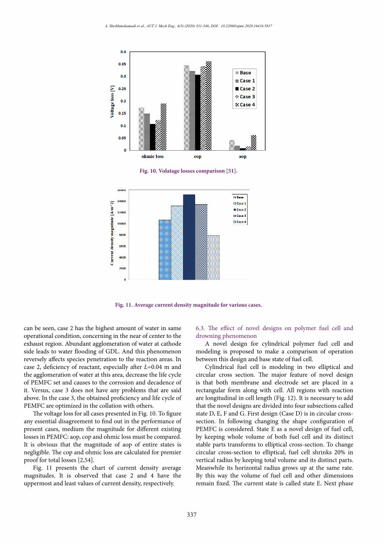
The voltage loss for all cases presented in Fig. 10. To figure any essential disagreement to find out in the performance of present cases, medium the magnitude for different existing losses in PEMFC: aop, cop and ohmic loss must be compared. It is obvious that the magnitude of aop of entire states is negligible. The cop and ohmic loss are calculated for premier proof for total losses [2,54].
Fig. 11 presents the chart of current density average magnitudes. It is observed that case 2 and 4 have the uppermost and least values of current density, respectively.
6.3. The effect of novel designs on polymer fuel cell and drowning phenomenon
A novel design for cylindrical polymer fuel cell and modeling is proposed to make a comparison of operation between this design and base state of fuel cell.
Cylindrical fuel cell is modeling in two elliptical and circular cross section. The major feature of novel design is that both membrane and electrode set are placed in a rectangular form along with cell. All regions with reaction are longitudinal in cell length (Fig. 12). It is necessary to add that the novel designs are divided into four subsections called state D, E, F and G. First design (Case D) is in circular cross-section. In following changing the shape configuration of PEMFC is considered. State E as a novel design of fuel cell, by keeping whole volume of both fuel cell and its distinct stable parts transforms to elliptical cross-section. To change circular cross-section to elliptical, fuel cell shrinks 20% in vertical radius by keeping total volume and its distinct parts. Meanwhile its horizontal radius grows up at the same rate. By this way the volume of fuel cell and other dimensions remain fixed. The current state is called state E. Next phase
Fig. 10. Volatage losses comparison [51].
Fig. 10. Volatage losses comparison [51].
Fig. 11. Average current density magnitude for various cases.
Fig. 11. Average current density magnitude for various cases.

A. Sheikhmohamadi et al., AUT J. Mech Eng., 4(3) (2020) 331-346, DOI: 10.22060/ajme.2020.16416.5817
338
initiates with introducing state F. State F is in circular cross-section and total volume of electrode set and membrane equals to state D. Total length of fuel cell should be reduced. Fig. 7 illustrates geometric parameters of cylindrical fuel cell for distinct states of novel design from front view. The novel design keeps total volume of fuel cell, electrode equivalent region and membrane constant by the increase in number of channels, electrode set and membrane in oval and circular cross-section (state G, F) [4].
Table 4 demonstrates dimensional and operational specifications for distinct states of Fig. 13. In the present design which depicted with oval and circular cross-sections, electrode set and membrane are both designed and represented through Fig. 13.
Fig. 14 points out gas channels inlet for different states.Fig. 15 displays polarization curve for distinct states of
novel design comparing with base state.It is quite clear all distinct cylindrical states comparing
with base state generate more outlet current. In this way, state G generates the maximum and state D the minimum current density. The current density variation is depicted in Fig. 10 at
voltage 0.4 [59]. Since there in no requirement to form a curve in electrode
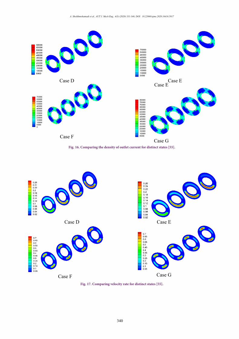
set and membrane in this design, their development (electrode set and membrane) is feasible and less costly. Indeed, it is one of the optimal features of current design. As it is obvious in Fig. 16, as the number of channels, electrode and membrane increases, and the density of outlet current increases too. Regarding shape and volume of gas channels in cylindrical design, there is less fluid current drop.
Fig. 17 demonstrates the velocity rate of reactive gases flow in anode and cathode gas channels. As it is seen, the increase in number of channels in constant cross-section for elliptical and circular states results in the increase in gas flow velocity. Since the increase in the number of electrodes set and membrane leads to the increase in channels inlet, thereupon, the channels inlet area reduces in state F and D comparing to states E and D. Therefore, the reduction in constant cross-section area leads to dramatic reduction in the amount of velocity. When velocity increases in G and F states and sequentially porosity area in electrode set and membrane increases to total channel area, there seems a dramatic increase
Case E Case D
Case G Case F
Fig. 12. the three-dimensional overview for novel design [55].
Fig. 12. the three-dimensional overview for novel design [55].
Table 4. Demonstrates dimensional [56-58].
Case G Case F Case E Case D Units Symbol Parameter 21.25 21.25 42.5 42.5 mm L Channel length 0.26 0.26 0.26 0.26 mm δGDL Diffusion layer thickness
0.0287 0.0287 0.0287 0.0287 mm δCL Thickness of catalyst 0.23 0.23 0.23 0.23 mm δMEM Membrane thickness 0.4 0.4 0.4 0.4 --- εGDL Porosity 0.4 0.4 0.4 0.4 --- εMEM Membrane porosity 1.8 2 1.8 2 mm d Horizontal Radius 2.2 2 2.2 2 mm e Vertical Radius
0.000085 0.000085 0.000085 0.000085 mm2 AEL Electrode Effective area 2.0643×10⁻⁶ 1.7081×10⁻⁶ 1.6844×10⁻⁶ 2.0865×10⁻⁶ mm2 Ach Gas Channel Inlet area
Table 4. Demonstrates dimensional [56-58].

339
A. Sheikhmohamadi et al., AUT J. Mech Eng., 4(3) (2020) 331-346, DOI: 10.22060/ajme.2020.16416.5817
Case E Case D
Case G Case F
Fig. 13. Elliptical and circular cylindrical fuel cell from front view [55].
Fig. 14. The orientation for gas flow entry to anode and cathode channels and form of their composition.
Fig. 15. The comparison of polarization graph for distinct states.
Fig. 13. Elliptical and circular cylindrical fuel cell from front view [55]
Fig. 14. The orientation for gas flow entry to anode and cathode channels and form of their composition.
Fig. 15. The comparison of polarization graph for distinct states.
A. Sheikhmohamadi et al., AUT J. Mech Eng., 4(3) (2020) 331-346, DOI: 10.22060/ajme.2020.16416.5817
340
14
Fig. 15 displays polarization curve for distinct states of novel design comparing with base state.
Fig. 15. The comparison of polarization graph for distinct states.
It is quite clear all distinct cylindrical states comparing with base state generate more outlet current. In this
way, state G generates the maximum and state D the minimum current density. The current density
variation is depicted in Fig. 10 at voltage 0.4 [59].
Case E Case D
Case G Case F
Fig. 16. Comparing the density of outlet current for distinct states [55].
Since there in no requirement to form a curve in electrode set and membrane in this design, their
development (electrode set and membrane) is feasible and less costly. Indeed, it is one of the optimal 14
Fig. 15 displays polarization curve for distinct states of novel design comparing with base state.
Fig. 15. The comparison of polarization graph for distinct states.
It is quite clear all distinct cylindrical states comparing with base state generate more outlet current. In this
way, state G generates the maximum and state D the minimum current density. The current density
variation is depicted in Fig. 10 at voltage 0.4 [59].
Case E Case D
Case G Case F
Fig. 16. Comparing the density of outlet current for distinct states [55].
Since there in no requirement to form a curve in electrode set and membrane in this design, their
development (electrode set and membrane) is feasible and less costly. Indeed, it is one of the optimal
14
Fig. 15 displays polarization curve for distinct states of novel design comparing with base state.
Fig. 15. The comparison of polarization graph for distinct states.
It is quite clear all distinct cylindrical states comparing with base state generate more outlet current. In this
way, state G generates the maximum and state D the minimum current density. The current density
variation is depicted in Fig. 10 at voltage 0.4 [59].
Case E Case D
Case G Case F
Fig. 16. Comparing the density of outlet current for distinct states [55].
Since there in no requirement to form a curve in electrode set and membrane in this design, their
development (electrode set and membrane) is feasible and less costly. Indeed, it is one of the optimal
Fig. 16. Comparing the density of outlet current for distinct states [55].
Case E Case D
Case G Case F
Fig. 17. Comparing velocity rate for distinct states [55].
Case E Case D
Case G Case F
Fig. 17. Comparing velocity rate for distinct states [55].
Case E Case D
Case G Case F
Fig. 17. Comparing velocity rate for distinct states [55].
Fig. 17. Comparing velocity rate for distinct states [55].

341
A. Sheikhmohamadi et al., AUT J. Mech Eng., 4(3) (2020) 331-346, DOI: 10.22060/ajme.2020.16416.5817
in outlet current density in fuel cell. However, in elliptical cross-section, the porous zone area slightly increasing leading to current density growing up into circular cross-section [60].
Fig. 18 displays oxygen mole fraction for distinct states in cathode side. In state G, the use of oxygen is higher than other states. This state takes the highest rate in dense outlet current and oxygen use. On the opposite side, state D bears the lowest rate in outlet current and the lowest oxygen use to all other states.
Fig. 19 displays the water molar concentration in distinct states in anode and cathode side. State G takes the highest
rate of water molar concentration in cathode and the lowest rate in anode (due to use of water). The amount of water generation in cathode bears the direct relation to fuel cell action. Accordingly, when the activity of fuel cell and then outlet flow density increases, the amount of water generation increases as well. As it is clear from the Fig. 19, the amount of generation and concentration of water bears a direct relation to fuel cell activity.
The comparison of mass fraction of water is indicated at Fig. 20 for new suggested design. As it was clarified before, the current parameter demonstrates the ability of membrane
Case E Case D
Case G Case F
Fig. 18. Comparing oxygen mass fraction for distinct states [55].
Case E Case D
Case G Case F
Fig. 18. Comparing oxygen mass fraction for distinct states [55].
Case E Case D
Case G Case F
Fig. 18. Comparing oxygen mass fraction for distinct states [55].
Fig. 18. Comparing oxygen mass fraction for distinct states [55].
Case E Case D
Case G Case F
Fig. 19. Mass fraction of water for different cases [26,55].
Fig. 19. Mass fraction of water for different cases [26,55].

A. Sheikhmohamadi et al., AUT J. Mech Eng., 4(3) (2020) 331-346, DOI: 10.22060/ajme.2020.16416.5817
342
in transport of hydrogen ion to various reaction regions. It should be added that the values of water concentration are the function of the water concentration in the membrane and at the interface of membrane and cathode catalyst layer. In the current design, two factors cause the higher amount of liquid water mass fraction in cathode side. Generally, two factors lead to such condition. First in the novel design, there is higher amount of generated water in cathode side. As the accumulation of water in cathode increases, liquid water increases too. In this way the probability of transport phenomenon specifically in lower voltages increases. Second, both the effective electrode area and membrane is relatively low [4,61].
7. CONCLUSIONIn this paper a 3D numerical model has presented. In
the following an innovative design for the PEMFC is given to enhance its efficiency. Also, the comparison about the studying the transport phenomena for base model and new design is performed [62,63]. At first the effect of locating semi-circular prominences on GDLs is studied and by posing these prominences the absorbing area of species is increased and the performance of cell grows up. In the following the performance of cylindrical shape PEMFC is investigated. These designs are divided into four subsections called D, E, F, G states. All distinct cylindrical states, comparing with base state, generate higher outlet current. Among all states, state G generates the highest and state D the lowest amount of current. The increment of the channels in fixed width size for cylindrical cases leads to the velocity increase in gas current [2]. This is because of the increase in number of electrode set,
membrane and consequently channel. This process leads to the decrease in channel inlets (G and F state) comparing to D and E states. Accordingly, when cross-section area reduces in constant state, the amount of velocity considerably increases. Very probably transport phenomenon will be quite pertinent if mismanagement of water runs in states E and D. Since the channel inlet area for state G is more and its velocity of species inside channels high, the amount of consuming ability for the current state is higher than other states. State F bears the lowest amount of consuming ability. A model of simulation fuel cell in Lattice-Boltzmann Method is recommended for future studies.
Nomenclature
a :Water activity
C :Molar concentration [mol/m3]D :Mass diffusion coefficient [m2 /s]F :Faraday constant [C /mol]I :Local current density [A /m2]J :Exchange current density [A/m2]K :Permeability [m2]M :Molecular mass [kg/mol]nd :Electro-osmotic drag coefficientP :Pressure [Pa]R :Universal gas constant [J/mol. K]T :Temperature [K]t :Thickness
Case E Case D
Case G Case F
Fig. 20. Mass fraction of liquid water at longitude direction [4,55].
Fig. 20. Mass fraction of liquid water at longitude direction [4,55].

343
A. Sheikhmohamadi et al., AUT J. Mech Eng., 4(3) (2020) 331-346, DOI: 10.22060/ajme.2020.16416.5817
u :Velocity vectorVcell :Cell voltageVoc :Open-circuit voltageW :WidthX :Mole fractionGreek Letter
α :Water transfer coefficient
effε :Effective porosity
ρ :Density [kg/m3]
eφ:Electrolyte phase potential (varies from -1 to 1) [V]
µ :Viscosity [kg/m.s]
mσ :Membrane conductivity [1/Ω.m]
λ :Water content in the membrane
ζ :Stoichiometric ratio
η :Over potential [V]
effλ :Effective thermal conductivity [W/m.K]
SUBSCRIPTS AND SUPERSCRIPTSACH :Anode ChannelCCH :Cathode ChannelABP :Anode BipolarCBP : Cathode BipolarAGDL :Anode Gas Diffusion LayerCGDL :Cathode Gas Diffusion LayerACL :Anode Catalyst LayerCCL : Cathode Catalyst Layera :Anodec :Cathodech :Channelk :Chemical speciesm :MembraneMEA :Membrane electrolyte assemblyref :Reference valuesaturation :satw :Watera :Anode
REFERENCES[1] M. Ecker, J. B. Gerschler, J. Vogel, S. Käbitz, F. Hust, P. Dechent, and D.
U. Sauer, Analyzing calendar aging data towards a lifetime prediction model for lithium-ion batteries, in: nth Electric Vehicle Symposium
2012, EVES 2012, Los Angeles, CA, US, May 6-9, 2012, pp. 47-57.[2] B. Pivovar, Catalysts for fuel cell transportation and hydrogen related uses,
Nature Catalysis, 2(7) (2019) 562-565.[3] S.R. Nima Ahmadi, Journal of the Brazilian Society of Mechanical
Sciences and Engineering, in, Springer Berlin Heidelberg, 2019.[4] H. Samanipour, N. Ahmadi, I. Mirzaee, M. Abbasalizade, The Study of
Cylindrical Polymer Fuel Cell’s Performance and the Investigation of Gradual Geometry Changes’ Effect on Its Performance, Periodica Polytechnica Chemical Engineering, 63(3) (2019) 513-526.
[5] N. Ahmadi, S. Rezazadeh, I. Mirzaee, Study the effect of various operating parameters of proton exchange membrane, Periodica Polytechnica Chemical Engineering, 59(3) (2015) 221-235.
[6] T. Van Nguyen, Modeling two-phase flow in the porous electrodes of proton exchange membrane fuel cells using the interdigitated flow fields, in: Tutorials in Electrochemical Engineering-Mathematical Modeling: Proceedings of the International Symposium, The Electrochemical Society, 1999, pp. 222.
[7] S. Korkut, M.S. Kilic, S. Uzuncar, B. Hazer, Novel Graphene-Modified Poly (styrene-b-isoprene-b-styrene) Enzymatic Fuel Cell with Operation in Plant Leaves, Analytical Letters, 49(14) (2016) 2322-2336.
[8] N. Ahmadi, S. Rezazadeh, I. Mirzaee, N. Pourmahmoud, Three-dimensional computational fluid dynamic analysis of the conventional PEM fuel cell and investigation of prominent gas diffusion layers effect, Journal of mechanical science and technology, 26(8) (2012) 2247-2257.
[9] F.A. Al‐Sulaiman, F. Hamdullahpur, I. Dincer, Trigeneration: a comprehensive review based on prime movers, International journal of energy research, 35(3) (2011) 233-258.
[10] S. Martemianov, Gueguen, M., Grandidier, J., & Bograchev, D, Mechanical effects in PEM fuel cell: application to modeling of assembly procedure, Journal of Applied Fluid Mechanics, 2(2) (2009) 49-54.
[11] N. Ahmadi, N. Pourmahmoud, I. Mirzaee, S. Rezazadeh, Three-dimensional computational fluid dynamic study on performance of polymer exchange membrane fuel cell (PEMFC) in different cell potential, Iranian Journal of Science and Technology. Transactions of Mechanical Engineering, 36(M2) (2012) 129.
[12] W. Chang, J. Hwang, F. Weng, S. Chan, Effect of clamping pressure on the performance of a PEM fuel cell, Journal of Power Sources, 166(1) (2007) 149-154.
[13] N. Ahmadi, H. Taraghi, M. Sadeghiazad, A numerical study of a three-dimensional proton exchange membrane fuel cell (PEMFC) with parallel and counter flow gas channels, Iranian Journal of Science and Technology Transactions of Mechanical Engineering, 39(M2) (2015) 309-323.
[14] J.C. Amphlett, R.M. Baumert, R.F. Mann, B.A. Peppley, P.R. Roberge, T.J. Harris, Performance modeling of the Ballard Mark IV solid polymer electrolyte fuel cell I. Mechanistic model development, Journal of the Electrochemical Society, 142(1) (1995) 1-8.
[15] C. Werner, L. Busemeyer, J. Kallo, The impact of operating parameters and system architecture on the water management of a multifunctional PEMFC system, International Journal of Hydrogen Energy, 40(35) (2015) 11595-11603.
[16] O.-J. Kwon, H.-S. Shin, S.-H. Cheon, B.S. Oh, A study of numerical analysis for PEMFC using a multiphysics program and statistical method, International Journal of Hydrogen Energy, 40(35) (2015) 11577-11586.
[17] D. Lee, J.W. Lim, S. Nam, I. Choi, Gasket-integrated carbon/silicone elastomer composite bipolar plate for high-temperature PEMFC, Composite Structures, 128 (2015) 284-290.
[18] F.A. Uribe, S. Gottesfeld, T.A. Zawodzinski, Effect of ammonia as potential fuel impurity on proton exchange membrane fuel cell performance, Journal of the Electrochemical Society, 149(3) (2002) A293-A296.
[19] E.A. Ticianelli, C.R. Derouin, S. Srinivasan, Localization of platinum in low catalyst loading electrodes to to attain high power densities in SPE fuel cells, Journal of electroanalytical chemistry and interfacial electrochemistry, 251(2) (1988) 275-295.
[20] S. Rezazadeh, H. Sadeghi, N. Ahmadi, Numerical investigation of step-liked bipolar plates effect on proton exchange membrane fuel cell performance, in: 2017 International Conference on Engineering and Technology (ICET), IEEE, 2017, pp. 1-11.
[21] D. Natarajan, T. Van Nguyen, A two-dimensional, two-phase,

A. Sheikhmohamadi et al., AUT J. Mech Eng., 4(3) (2020) 331-346, DOI: 10.22060/ajme.2020.16416.5817
344
multicomponent, transient model for the cathode of a proton exchange membrane fuel cell using conventional gas distributors, Journal of the Electrochemical Society, 148(12) (2001) A1324-A1335.
[22] N. Ahmadi, S. Rezazadeh, M. Yekani, A. Fakouri, I. Mirzaee, Numerical Investigation of The Effect of Inlet Gases Humidity on Polymer Exchange Membrane Fuel Cell (PEMFC) Performance, Transactions of the Canadian Society for Mechanical Engineering, 37(1) (2013) 1-20.
[23] K.W. Lum, J.J. McGuirk, Three-dimensional model of a complete polymer electrolyte membrane fuel cell–model formulation, validation and parametric studies, Journal of Power Sources, 143(1-2) (2005) 103-124.
[24] D.H. Ahmed, H.J. Sung, Effects of channel geometrical configuration and shoulder width on PEMFC performance at high current density, Journal of Power Sources, 162(1) (2006) 327-339.
[25] M. Gholizadeh, M. Ghazikhani, I. Khazaee, Experimental study of humidity changes on the performance of an elliptical single four-channel PEM fuel cell, Heat and Mass Transfer, 53(1) (2017) 233-239.
[26] N. Ahmadi, A. Dadvand, S. Rezazadeh, I. Mirzaee, Analysis of the operating pressure and GDL geometrical configuration effect on PEM fuel cell performance, Journal of the Brazilian Society of Mechanical Sciences and Engineering, 38(8) (2016) 2311-2325.
[27] S. Ebrahimi, R. Roshandel, K. Vijayaraghavan, Power density optimization of PEMFC cathode with non-uniform catalyst layer by Simplex method and numerical simulation, International Journal of Hydrogen Energy, 41(47) (2016) 22260-22273.
[28] N.J. Cooper, A.D. Santamaria, M.K. Becton, J.W. Park, Investigation of the performance improvement in decreasing aspect ratio interdigitated flow field PEMFCs, Energy conversion and management, 136 (2017) 307-317.
[29] W.-M. Yan, H.-Y. Li, W.-C. Weng, Transient mass transport and cell performance of a PEM fuel cell, International Journal of Heat and Mass Transfer, 107 (2017) 646-656.
[30] J.X. Liu, H. Guo, F. Ye, C.F. Ma, Two-dimensional analytical model of a proton exchange membrane fuel cell, Energy, 119 (2017) 299-308.
[31] N. Ahmadi, A. Dadvand, I. Mirzaei, S. Rezazadeh, Modeling of polymer electrolyte membrane fuel cell with circular and elliptical cross‐section gas channels: a novel procedure, International Journal of Energy Research, 42(8) (2018) 2805-2822.
[32] N. Ahmadi, S. Rezazadeh, A. Dadvand, I. Mirzaee, Modelling of gas transport in proton exchange membrane fuel cells, Proceedings of the Institution of Civil Engineers-Energy, 170(4) (2016) 163-179.
[33] E. Shakerinejad, M. Kayhani, M. Nazari, A. Tamayol, Increasing the performance of gas diffusion layer by insertion of small hydrophilic layer in proton-exchange membrane fuel cells, International Journal of Hydrogen Energy, 43(4) (2018) 2410-2428.
[34] M. Nazari, E. Shakerinejad, M. Kayhani, Tailored Surface Wettability of Gas Diffusion Layer in Polymer Electrolyte Membrane Fuel Cells: Proposing a Pore Scale‐Two Phase Design, Fuel Cells, 18(6) (2018) 698-710.
[35] M. Afra, M. Nazari, M.H. Kayhani, M. Sharifpur, J. Meyer, 3D experimental visualization of water flooding in proton exchange membrane fuel cells, Energy, 175 (2019) 967-977.
[36] agupubs, agupubs, in: Effects of wind‐powered hydrogen fuel cell vehicles on stratospheric ozone and global climate, 2008.
[37] N. Zamel, X. Li, Effective transport properties for polymer electrolyte membrane fuel cells–with a focus on the gas diffusion layer, Progress in energy and combustion science, 39(1) (2013) 111-146.
[38] J. Ge, H. Liu, A three-dimensional two-phase flow model for a liquid-fed direct methanol fuel cell, Journal of Power Sources, 163(2) (2007) 907-915.
[39] S. Litster, N. Djilali, Mathematical modelling of ambient air-breathing fuel cells for portable devices, Electrochimica Acta, 52(11) (2007) 3849-3862.
[40] V. Gurau, H. Liu, S. Kakac, Two‐dimensional model for proton exchange membrane fuel cells, AIChE Journal, 44(11) (1998) 2410-2422.
[41] N.A. Sajad Rezazadeh, Nader Pourmahmoud, Iraj Mirzaee, Two dimensional numerical analysis of operating and geometrical parameters effect on the fuel cell performance, International Journal of Heat and Technology, 31(2) (2013) 43-50.
[42] H. Guo, H. Chen, F. Ye, C.F. Ma, Baffle shape effects on mass transfer and power loss of proton exchange membrane fuel cells with different baffled flow channels, International Journal of Energy Research, 43(7) (2019) 2737-2755.
[43] R.B. Ferreira, Falcão, D. S., Oliveira, V. B., & Pinto, A. M. F, A one‐dimensional and two‐phase flow model of a proton exchange membrane fuel cell, ournal of Chemical Technology & Biotechnology, 90(9) (2015) 1547-1551.
[44] J.-K. Kuo, T.-H. Yen, Three-dimensional numerical analysis of PEM fuel cells with straight and wave-like gas flow fields channels, Journal of Power Sources, 177(1) (2008) 96-103.
[45] P. Chavan, Hydrogen fuel cell vehicle, International Journal of Latest Trends in Engineering and Technology (IJLTET), 7(3) (2016) 192-196.
[46] S.R. Mehdi Mehrabi , Mohsen Sharifpur , Josua P. Meyer, Institutional Repository of the University of Pretoria, in: Proceedings of the ASME 2012 10th Fuel Cell Science, Engineering and Technology Conference FuelCell, 2012, San Diego, CA, USA, July 23, 2013, pp. 447-452.
[47] L. Wang, A. Husar, T. Zhou, H. Liu, A parametric study of PEM fuel cell performances, International journal of hydrogen energy, 28(11) (2003) 1263-1272.
[48] M.A.S. Al-Baghdadi, H.A.S. Al-Janabi, Influence of the design parameters in a proton exchange membrane (PEM) fuel cell on the mechanical behavior of the polymer membrane, Energy & fuels, 21(4) (2007) 2258-2267.
[49] L. Karpenko-Jereb, C. Sternig, C. Fink, V. Hacker, A. Theiler, R. Tatschl, Theoretical study of the influence of material parameters on the performance of a polymer electrolyte fuel cell, Journal of power sources, 297 (2015) 329-343.
[50] E. Antolini, R. Passos, E.A. Ticianelli, Effects of the carbon powder characteristics in the cathode gas diffusion layer on the performance of polymer electrolyte fuel cells, Journal of Power Sources, 109(2) (2002) 477-482.
[51] N. Ahmadi, S. Rostami, Enhancing the performance of polymer electrolyte membrane fuel cell by optimizing the operating parameter, Journal of the Brazilian Society of Mechanical Sciences and Engineering, 41(5) (2019) 220.
[52] M. Yekani, M. Masoodi, N. Ahmadi, M.S. Azad, K. VAHEDI, A CFD MODEL FOR POLYMER FUEL CELL, Key Engineering Materials, Volume 1: Current State-of-the-Art on Novel Materials, 1 (2014) 71.
[53] S. Cano-Andrade, M. Von-Spakovsky, C. Rubio-Arana, Effect of Radial Plate Flow Field Distribution on Current Density in a Proton Exchange Membrane (PEM) Fuel Cell, in: ASME 2007 International Mechanical Engineering Congress and Exposition, American Society of Mechanical Engineers Digital Collection, 2007, pp. 617-625.
[54] I. Dincer, and Canan Acar, A review on clean energy solutions for better sustainability, International Journal of Energy Research, 5(39) (2015) 585-606.
[55] D.E. Curtin, Robert D. Lousenberg, Timothy J. Henry, Paul C, Advanced materials for improved PEMFC performance and life, Journal of power Sources, 1-2(131) (2004) 41-48.
[56] A. Mohammadi-Ahmar, B. Osanloo, A. Solati, J. Ghasemi, Performance improvement of the circular tubular PEMFC by using different architectures and number of layers, Energy conversion and management, 128 (2016) 238-249.
[57] J.B.S. Christian, Sean P. E, Tungsten Cathode Catalyst for PEMFC, in, United States. Department of Energy. Office of Energy Efficiency and Renewable Energy. USDOE - Office of Energy Efficiency and Renewable Energy (EE), OSRAM SYLVANIA Products Inc. Place of Publication: United States, 2006, pp. 1-22.
[58] M. Afzal, Mohsin Saleemi, Baoyuan Wang, Chen Xia, Wei Zhang, Yunjuan He, Jeevan Jayasuriya, and Bin Zhu, Fabrication of novel electrolyte-layer free fuel cell with semi-ionic conductor (Ba0. 5Sr0. 5Co0. 8Fe0. 2O3− δ-Sm0. 2Ce0. 8O1. 9) and Schottky barrier, Journal of Power Sources, 1(328) (2016) 136-142.
[59] A. Solati, B. Nasiri, A. Mohammadi-Ahmar, K. Mohammadi, A.H. Safari, Numerical investigation of the effect of different layers configurations on the performance of radial PEM fuel cells, Renewable Energy, (2019).
[60] W. Yang, T. Zhao, A two-dimensional, two-phase mass transport model for liquid-feed DMFCs, Electrochimica Acta, 52(20) (2007) 6125-6140.

345
A. Sheikhmohamadi et al., AUT J. Mech Eng., 4(3) (2020) 331-346, DOI: 10.22060/ajme.2020.16416.5817
[61] N. Mendis, K. M. Muttaqi, and Sarath Perera, Management of low-and high-frequency power components in demand-generation fluctuations of a DFIG-based wind-dominated RAPS system using hybrid energy storage, IEEE transactions on industry applications, 3(50) (2013) 2258-2268.
[62] R.R.F. Mahmoodi, Transient Three-dimensional Simulation of a Metal
Hydride Hydrogen Storage Tank Interconnected to a PEM Fuel Cell by Heat Pipes, Iranian Journal of Hydrogen and Fuel Cell (IJHFC) 2(6) (2019) 117-132.
[63] S.Y. Xingwen Yu, Recent advances in activity and durability enhancement of Pt/C catalytic cathode in PEMFC, Journal of Power Sources, 1(172) (2007) 133-144.
HOW TO CITE THIS ARTICLEA. Sheikhmohamadi, I. Mirzaee, N. Pourmahmoud, N. Ahmadi, The Effect of Novel Designs on the Performance of Polymer Electrolyte Membrane Fuel Cell, AUT J. Mech Eng., 4(3) (2020) 331-346.
DOI: 10.22060/ajme.2020.16416.5817

This pa
ge in
tentio
nally
left b
lank