eheeeeeemhhmhi i.eomomom - dtic.mil · (3.8) if cos 0, 0, then the azimuthal angle 0 is uniquely...
TRANSCRIPT

-A199 434 ESTIMATION OF AZIRUTURL AND VERTICAL ARRIVAL MC 1 -ROTRBLE HORIZONT (U) DEFENCE RESEARCH ESTABLISHMENT
ATLANTIC DARTMOUTH (NOVA SCOTI 8 A TEENNOLK ET ALUNCLASSIFIED JUL 87 DREA/87/18i F/G 17/1
EEEEEEEEEEill
EhEEEEEEmhhmhII.Eomomom

jj 2.0
tJL2 1.0 4III . *'2----12
*: IINth I~g Il
1
II • • • 111 'iii' • •

4UNLIMITED DISTRI BUTION
I 'National Defence Defense Nationale 1 ftEOYResearch and rBureau de Recherche
I Development Branch et Developpment
REPORT 87/101JulIy 1987
a)1
IESTIMATION OF AZIMUTHAL AND[ VERTICAL ARRIVAL ANGLES AT A
_ ROTATABLE HORIZONTAL LINE ARRAY
B. A. Trenholm - ames.A.. Theriault
DISLTUTICN STrATEMEN-T AI
Approv'd for publiac relaocea
Distribution UraUmited
Defence Centre de*Research Recherches pour la
Establishment Defense D "CAtlantic Atlantique D I
ELECTEOCariadgi
8.7 1i 30 03

44
r.r
. EE4 EERHETBIHETALNI ETR ERCECE ORL FNEALNIU
90R V TET PO O 029GOESRE .. 11
DATOT,-4.TLPOE
DATOT.NI
.2 Z 40;4 .10 2 Z
.4""" '" "' : " ' ' ", 5 .. .... .. . } ¢ ~

UNLIMITED DISTRIBUTION
I ,National Defence Weense NationaleResearch and Bureau do RechercheDevelopment. Branch at DWveloppmeont
ESTIMATION OF AZIMUTHAL ANDVERTICAL ARRIVAL ANGLES AT A
ROTATABLE HORIZONTAL LINE ARRAY
B.A. Trenhoim - James A. Theriault
July 1987
*Approved by FLF. Brown Director/Underwater Acoustics Division
DISTRIBUTION APPROVED BY
* CHIEF D.R.E.A.
REPORT 87/101
Deems Centre deIResearch Recherches pour Ia
Establishmnent WofnseAtlantic Atlantique
Caaa

ABSTRACT
A Horizontal Line Array (HLA) receiver is subject to left-right bearing ambiguity. It isalso susceptible to bearing bias caused by non-zero vertical arrival angles. The true bearingangle and the vertical arrival angle may both be estimated if a second observation is made,with the HLA rotated to a new orientation. A closed-form solution is presented for the caseof stationary source and receiver. For small observation errors, the resulting errors in theestimated angles can also be expressed in closed form.
RtSUMt
*• Les ricepteurs de sonar en ligne horizontale (Horizontal Line Array, HLA) sont sujets i desambiguitds a gauche ou & droite quant au relivement. Uls sont 6galement sujets i des erreurs derelivernent causies par des angles d'arrivie non nuls par rapport i la verticale. Le relivement'veritable et l'angle d'arrivie par rapport i la verticale peuvent tous deux itre -Stimds si oneffectue une deuxi~me observation apres avoir aligni le HLA sur un nouveau cap. Une solutionanalytique complite est prdsent6e pour le cas d'une source et d'un r6cepteur stationnaires. Pourde petites erreurs d'observation, lea erreurs risultantes des angles estim6s peuvent 6galementitre exprimdes sous forme de solution analytique complite.
L
0%
Ket
Accession ForNTIS GRA&I
IDTIC TABUniannounced EJustifi catio
By_______ / OqConens Distribution 4w
Avnid -Lility Codes40r
~'.1and/or
AbstractDit -ecaU
Table of Contents Ili____
1 Introduction1
2 The lILA Bearing Bias Problem 2
3 Estimation of Azimuthal and Vertical Arrival Angles 4
3.1 Solution by Rotation of the Array............................... 4
* 3.2 Assumptions and Restrictions.................................. 4
3.3 The Analytic Model........................................ 5
3.4 The Analytic Solution...................................... 6
4 Graphic Representation 7
4.1 Graphic Estimation of Vertical Arrival Angle....................... 7
4.1.1 Example of Method (a)................................. 8
4.1.2 Example of Method (b)................................. 8
4.1.3 Example of Method (c).................................8
4.1.4 Example of Method (d)................................ 12
4.2 Graphic Estimation of Azimuthal Angle.......................... 14
5 Error Estimates IS
S5.1 Model of Observation Errors.................................. 15
Ps 5.1.1 Errors in coop...................................... 15
5.1.2 Errors in Rotation Angle W ............................ 16
5.2 Resulting Errors in the Closed-Form Solution. .. .. .. .. ... ... ... .. 17
5.2.1 Maximum Errors..................................... 17
5.2.2 R.M.S. Errors....................................... 18
5.3 An Example of Maximum Errors .. ............................ 19
AllS

5.3.1 Errors When Vertical Angle Bias is Not Removed. .. .. ... .. .... 19
5.3.2 Errors in Estimated Azimuthal Angle after Rotation. .. .. .. .. .... 19
S5.3.3 Errors in Estimated Vertical Angle after Rotation. .. .. .. ... .... 19
5.4 General Trends. .. .. .. .. ... ... ... ... ... ... .. ... ... .. 22
6 Conclusions 23
4-Bibliography 24
Appendices 25
A Parametric Analysis of Maximum Errors 25
B Parametric Analysis of R.M.S. Errors 31
C The Effect of Error In Rotation Angle 37
0.1 Maximum Errors Due to Error in Rotation Angle.................... 38
C.2 R.M.S. Errors Due to Error in Rotation Angle...................... 43
.1'~.~iv

1 Introduction
A Horizontal Line Array (HLA) receiver is a one-dimensional array of sensors lying in thehorizontal plane. An HLA can be used to detect an underwater acoustic source, and to obtainan estimate of the direction of the arriving signal. Due to the one-dimensional nature of theHLA, the bearing estimates are subject to left-right ambiguity. HLA bearing estimates arealso susceptible to bearing bias caused by non-zero vertical arrival angles.
The true bearing angle and the vertical arrival angle may both be estimated if a secondobservation is made. This can be accomplished by rotating the HLA to a new orientation. Theproblem can be modelled as two nonlinear equations in two unknowns. A closed-form solutionis presented for the case of stationary source and receiver. Error bounds on the estimatescan be calculated as a function of observation errors, HLA rotation angle, and signal arrivalgeometry. For small observation errors, the resulting errors in the estimated angles can aiso
0 be expressed in closed form.
-I.
i

2 The HLA Bearing Bias Problem
Figure 2.1 illustrates the geometry of a plane wave signal arriving at a Horizontal LineArray. The HLA is lying in the plane 0 = 0. The azimuthal angle 0 is measured in the plane,clockwise from the HLA axis. The arriving signal has azimuthal angle 0 and vertical arrivalangle 4.
The HLA sensors may be processed using one of several methods, to provide an esti-mate of cos 0, where f is the angle of incidence between the array axis and the signal vector[Walker, 1985]. The angle of incidence is a function of the azimuthal angle and the verticalangle:
cos 0= cos 0 cos 4. (2.1)
The estimate of arrival direction therefore has a left-right ambiguity:
6 = +Oo (2.2)
where
80 = cos- I (cos cos 4) ; 0 < 0o < 1800 • (2.3)
If the signal vector is in the plane 4 = 0, then cos0 = cos0. However, if the verticalarrival angle 4 is non-zero, then the measured angle of incidence P may not be equal to theazimuthal angle 0. 0 is therefore a biased estimator of 0. The effect of non-zero '0 is to makecos 0 smaller than cos 9. Therefore # is biased toward the broadside direction cos 0 = 0.
A graph will be used to show the magnitude of the bias, for 0 between 0 0and 1800. Thebias, B, is defined as follows:
B= #-
= cos-1 (cos0cos) -0 ; 00 < < 1800 (2.4)= -cos- 1 (cos~coso)-9 ; -180. <e<00
Figure 2.2 shows the bias error B as a function of 0, for several values of the vertical arrivalangle 4). It is evident from this figure that bearing bias can be a serious problem. Themaximum bias occurs in the endfire directions, 0 = 0 and 9 = 1800; the maximum absolutebias error is equal to the vertical arrival angle 10)1:
.; IBI 5 10)1 .(2.5)
2
IZ% %
A,

Fi ur 2 1: A r iv lSng e go m tr
SC ~VERTICAL ANGLE 0
25 S.w~ - -20.0
hi - 40o..
a 530_____ 0____ 0__ 120___ 150____ISO.
AZMTA ANGL IN DEGEE
Fiue22 HABaig isa fnto f zmta age0 orsvrlvauso hvertial arivalangl
4 -' 3
%25

3 Estimation of Azimuthal and VerticalArrival Angles
*3.1 Solution by Rotation of the Array
The true azimuthal angle and the vertical arrival angle may both be estimated if a secondobservation is made. This can be accomplished by rotating the Horizontal Line Array toa new orientation. The problem may then be approximated as two nonlinear equations intwo unknowns. A closed-form solution can be obtained for the case of stationary source andreceiver. For small errors in the observations and in the assumed rotation angle, the resulting
* errors in the estimated angles can also be expressed in closed form.
3.2 Assumptions and Restrictions
A number of simplifying assumptions are made in order to find a computable closed-formsolution:
(a) The array is assumed to be perfectly stable; errors due to tilting and stretching of thearray are not included. However, the standard deviation of the angular observation errormay be increased to approximate this effect.
(b) The source and receiver positions are assumed to be stationary. However, the effect ofLminor relative motion may be approximated by enlarging the error bounds for the final
estimated angles.
(c) The propagation path is assumed to be the same for both observations; that is, the verticalarrival angle 0 remains constant. This assumption restricts the usefulness of the methodto environments in which the vertical arrival angle is stable.
K (d) The rotation angle At is assumed to be larger than the magnitude of the observationerrors e, i.e. Isin A01 a.
'.
.
4

3.3 The Analytic Model
The Horizontal Line Array is rotated through an angle A#, where sin A# $ 0. The ob-servations cos #1 and cos 82 are made before and after rotation, respectively. Let 01 and 02 bethe azimuthal angles clockwise from the array forward endfire direction before and after rota-tion. Let 4,1 and 02 be the corresponding vertical arrival angles before and after rotation. Thenit is possible to describe the problem by two equations in four unknowns:
cos8 1 = cos 91 cos 41 (3.1)
cos 2 =cos 02 cos2 (3.2)
The number of unknowns may be reduced by assuming 0i = 0 = , and 01 = 0, 020 - AO, to obtain two equations in two unknowns:
cosflx = cos 0 cos 0 (3.3)
cos 62 = cos (9 - A#) cos4. (3.4)
The assumption of constant vertical arrival angle 4 is reasonable if the measurementsare made simultaneously by a pair of collocated HLAs, or if the acoustic propagation path isstable. For instance, in underwater acoustics, bottom reflected paths arriving at steep verticalangles are relatively stable.
The assumpt'on of constant azimuthal angle 0 is reasonable if there is little relative move-ment of source and receiver between observations. That is,
(a) the measurements are made simultaneously by a pair of collocated HLAs, or
(b) the source and receiver are stationary, or
(c) the source is in the far field.
In practice, a finite amount of time At would be required to rotate the array. The array mayalso be shifted a distance D. Therefore an error E0 may be introduced in the estimate of 6
"-, due to motion of a source with velocity V at range R:',
This error should be included when calculating the total error in the final estimate of 0. Forexample, if D = 0.075nm, V - Ikt, At = 0.1hr and R = 3nm, then E0 P 3.30 .
.5
•% %6
"* ,

4 3.4 The Analytic Solution
The analytic solution may be found by expanding equation 3.4 to obtain:
coo 0 cos = cos81 (3.6)
sin 0cos COS2 c9s61 COn O (3.7)sin A8
The vertical arrival angle 4 is found by squaring and summing equations 3.6 and 3.7 to obtain:
F 61 2 COS 2 - COS lCOS A 0 )21 <90Cos4= [(os + sinAO ; 0< <90 . (3.8)
If cos 0, 0, then the azimuthal angle 0 is uniquely defined by:
Scos = cos #1/cos 0 (3.9)sinG= (cos82 - cos icos A0)/(sinAScos,)
If 4 = 90', then 0 is indeterminate. Also, when observation errors are present, care must be
taken to ensure that I cos 0 1, 1 cos 01 and I sin 01 do not exceed unity.
The next section shows graphs of the relationship between 61, P2 and 4,, and illustratesthe sensitivity of the solution to problem geometry.
*. Section 5 returns to the analytic solution to derive closed-form expressions for maximum
and r.m.s. errors in the estimated values of azimuthal angle 0 and the cosine of the verticalangle 4.
0
6
0%%Z*
................................................

4 Graphic Representation
4.1 Graphic Estimation of Vertical Arrival Angle
The HLA angle estimation problem can be solved directly using a computer. However, itis instructive to examine graphs of the relationships between the parameters of interest. Suchgraphs provide an appreciation for the sensitivity of the solution to observation errors. Graphsmay also provide an alternative to using a computer. However, the use of such graphs may becumbersome due to the large number of variables (PI, 62, AO, 0, and 4).
To obtain a graphic solution, it is convenient to first estimate the vertical angle 4. Thereare several ways to solve graphically for 4). Four methods will be considered here. In each
* A of these methods, separate graphs are required corresponding to discrete values of the rotationangle AO.
Method (a) In this method, #I is plotted against 02 for several discrete values of 4'. Thisallows graphic resolution of left-right ambiguity, but requires a quadrant search for thecorrect solution.
Method (b) This method uses absolute angles only. 1,61 is plotted against 1#21 for several
discrete values of 4. This graph may also be used to resolve left-right arnibiguity, butrequires careful interpretation. The larger scale is easier to read.
Method (c) This method uses a nonlinear scale. cos8 1 is plotted against cosP2 for severaldiscrete values of 4). This is similar to Method (b), except for the use of the cosinescale. Horizontal Line Array resolution capability is usually uniform in the cosine do-main. That is, cos# can be estimated with an accuracy which is independent of f. Thegraph for Method (c) therefore provides a better feeling for sensitivity to observationerrors.
Method (d) This method is based on the deviation between the expected and observed valuesof 1021. Given the observation I#11, two forecasts are made for 1#21, for right and leftbearing hypotheses, under the assumption that 4) = 0. After rotation, the forecastwhich agrees most closely with the observed value 1,21I determines the choice of right orleft bearing. If the agreement is not exact, the difference may be used to estimate themagnitude of 4). This method allows large values of 4) to be identified.
.1
..
7
o
04,.
*4,.

4.1.1 Example of Method (a)
Figure 4.1 shows the graphs for Method (a), for rotation angles of 200,450, and 900. Theobserved values of cos I and cos #2 do not immediately indicate the signs of these angles. How-ever, for any pair of observations, there is only one signed pair that fits the data. The answeris found by searching through the four possible sign pairs:
H 1,-1021)
Consider the following example:
A9 = 200, 1011 = 96.40, I1= 108.80
In figure 4.1, the only solution pair is:
I = -96.4*, #2 = -108.8 °
which lies on the contour 4, = 50 ° . These values are difficult to read unless the plot is quitelarge. The estimated azimuthal angles, from Figure 4.5, are:
01 = -100o, 02 = -120'.
4.1.2 Example of Method (b)
Figure 4.2 shows the corresponding graphs for Method (b). Given I#1 and 621 as before,the vertical angle 4 may be read from the graph by interpolating between contours. This graphis easier to read because the contours are continuous and are plotted on a larger scale. Theleft-right ambiguity is resolved as follows. For any given vertical angle 4, there are two possiblea priori values of 1#21 for each observed angle 61. The largest value corresponds to rotation
.S away from the signal direction (01 and A8 have opposite signs); the smallest value correspondsto rotation towards the signal direction (01 and AO have the same sign).
4.1.3 Example of Method (c)
• Figure 4.3 shows the graphs for Method (c). The vertical angle 4 and the left-rightambiguity may be solved as for Method (b). The natural cosine scale gives a better appreciationof the ability to resolve different values of 4. For instance, a large value of 4, produces a largeshift in the observed value #I when the signal is arriving from the endfire directions 9 = 0 °and. = 180°; however the HLA is less capable of resolving these differences in the endfire directions.
8
N..N

:IS NOTATION ANGLE 60 t o.* VERTICAL NGLE 9
so -0.*..0 4 -0.0
0. 30.*
-120.I I..I-- --,ISO
-120
-2 -40 0 60 20 to0
NOTATION ANGLIC A0 So4.@
10/
S I*M- I0
Figur 4.:Etmto fvriaKrialageuiggahcMtoa
09
Jil4l

NOTATION ANGLE ae t .* VERTICAL ANGLE 0I O . . ., . . , . . . . .
,ox -0.*
#A It 6 1,8 A 9 < 0 - . .1*, '***-'-S.... 40.0- - ./ - " 0 ."
SS-uV
30 1 61AO >
o 30 3O0 20 150 180
ROTATION ANGLE 60 - 45.*
i 130.
u 0 s o so t o 1-0 ISO
NOTATION ANGLE af - 90.0
SOI . . . ., . . . , . ., . .
#aISO--
120-
so-o
0 0 30 20 Ito ISO I0
ANL I ZG1
IFigure 4.2: Estimation of vertical arrival rgle using graphic Method (b)
I.--.".'_

ROTATION ANGLI AS0- O.' VERITICAL ANGLE *
t! s~no 20"-. -i- ."
6IA <',a 0 . . .... 40."10
* - -10..""
I o g I o l20 160
RtOTATIONI ANGLI 69 46.0
1-20
1500.
05 1 0 so. 0- 5
160
./ / .
00 60 0 120 150
ROTATION £1011I £0 - dO.0
e 4: E ion of v l -
%150
* " / ", "
. oo ,o /
• /ij ll -, Illli
Figure 4.3: Estmaio ofvri-7- ialage sn gahcMto c
nr, ., . - , "-%, . .,.4 ,"." i" v ,' - ,,,-. .,+ + . , ,.. ." " , """- - . "- " .-. " .,"," "", l' -. " -.---- ." .- ",-

4.1.4 Example of Method (d)
Figure 4.4 shows the graphs for Method (d). In this Method, the a priori estimate 1021, isbased on the assumption that the vertical arrival angle 0 is equal to 0. There are two possiblesolutions, corresponding to the ambiguous left and right solutions:
1421() = cos - ' (coS( 11 l + IAO)) ; < A < 0 (4.1)
'. or.1." IA216 ) = coo- 1 (cos(lai. - IAOl))) ; 6 1AO > 0. (4.2)
After the observation 1021, the chosen estimate 1421 is the one which agrees most closely withthe observation. The deviation 6 is then defined as follows:
b5 = I121- 1h8 (4.3)
Note, in Figure 4.2, that zero deviation is expected when 4' = 0. If 4 0 0, then a negativedeviation is expected when the rotation is away from the signal direction; a positive deviation
* is expected when the rotation is towards the signal direction.
Consider the same example again:
Af = 200, l1l 96.4 ° and 1621 = 108.80
Then:
121(*) = 116.40 and 42 1(b) = 76.40
The appropriate choice is
"4 1021 = 1I -a = 116.40,
which implies that #1 A0 < 0 and therefore
01= -96.4°.
However, there is not a perfect match between the predicted angle before rotation and theobserved angle after rotation. The deviation is:
6 = 1108.8o1 - 1116.4O1 = -7.6'.
From Figure 4.4, the value of the vertical arrival angle 4 is therefore 50*. Note that in Fig-4.' ure 4.4, the derivative discontinuties correspond to the corners of the rectangles in Figure 4.2.
12
IF"J
4"~ ~ ~ ,... .;4* 4 . ., *? " 4 44 *~ * -4%

NOTATION ANGLE AS - 80.' VERTICAL ANGLE o
so ..-' .- ..O.'
so - 0.*
50.0I- -' . . .. ,. . 430."
", * ; -+. . 50.~ .,.._ .+
do
-4o- '0.A8 < 0
sio so 90 ldo do5 180
ROTAIlON AINGLE A* 45.*
40-
J
-40 -6-
0 00 5 120 150 Igo
NOTATION ANGLE AS - 90.'
40 .. . .40-
o- A\! .. •,". ', . .
-20 '
40-
*0 so soO 1,0 Igo
ANG LE LN 1 0 110I
Figure 4.4: Estimation of vertical arrival angle using graphic Method (d)
13
1
iv
I%
ALL.

4.2 Graphic Estimation of Azimuthal Angle
Once the value of the vertical arrival angle 4) has been estimated, it may then be used tocorrect # to estimate the true bearing 0. Equation 2.1 defines the relationship between 0,4)and 6. Figure 4.5 shows the relationship between 9 and # for several values of 4).
To continue the example from the preceding section, it has been shown that, if
A# = 20, 1i1 = 96.40, and 1,21 = 108.80,
then it can be deduced that
#1 =96.4', #2 =108.8', and 4 = 500
Equation 2.1 or Figure 4.5 may be used to obtain the estimated azimuthal angles:
01 = -100°' , 1 = -120'
O
-r . 18 -. . , . . w . I . , . I • ' VERTICAL ANGLE
150-5.0a - - -- -10."
V 120- -20'
-U:. z -°- .-.".
hi 0-
~30 -'
00 30 60 90 120 150 160
AZIMUTHAL ANGLE 101 IN DEGREES
Figure 4.5: The true bearing 9 can be obtained from observation 6, if the vertical angle 4 isS.known.
-..
-.- ,...-.14
-...

a
5 Error Estimates
5.1 Model of Observation Errors
The analytic solution provides an exact closed form for the azimuthal and vertical arrivalangles. However there may be errors in the observed values cos #I and cos #2 as well as errorin the assumed rotation angle A8.
5.1.1 Errors in cosfi
It will be assumed that the standard deviation of the HLA observation cos 0 is independentof/':
SoaCo, = sin 0 (5.1)
where ao is the standard deviation of the bearing error in the broadside direction I1 = 900, fora specified signal-to-noise ratio. Figure 5.1 shows the observation errors A# corresponding tocos 0 ± r as a function jf fl for the case o0 = 1. Note that maximum errors IA6rmax occur inthe endfire directions, and also at angles 0+ IA#Xn and 180- IA6Imax. For small values of e,a second-order Taylor series expansion of cos# leads to an approximate expression for IA,6m,.:
* 2A COS - cos# -A (5.2)
- sin f + sign(sin 0)V(sin' ± 2 cos #A cos #) +
-A6 cos ; cosO$0 (5.3)
A j 0I Imax V1(5.4)
IAPI.- f FL-2o ft O.7Va . (5.5)
In this example, the maximum error is approximately 10.70.
15
WeJ
'9I

to "-I-
q..=1.00
I-
-to
m-S
0 30 60 90 120 150 180
* Figure 5.1: Bounds on error in the observed angle , corresponding to cosi ± sin o0, where
ac.
S5.1.2 Errors in Rotation Angle AO
The standard deviation in the rotation angle AO will be denoted by
= h (5.6)
*where h is given in degrees.
16
£%
-. ~~~~~~ -e *. 5. ,* *5. .J.. r~t*~5 *J= . ? 5 e_
ZIP A,'

5.2 Resulting Errors in the Closed-Form Solution
For suitably small errors c and h, the resulting errors in the estimated azimuthal and.vertical arrival angles 9 and 0 can be approximated in closed form. However, if the errors are.. . large, more elaborate methods are required to estimate the errors [Theriault, 1987].
First derivatives are obtained by differentiating equations 3.6 and 3.8 with respect tocos fi, coe #2 and A# to obtain the following expressions:
(cos _ sin e 2 (5.7)iicos 6I sinA8
a Cos _ sinG1 (5.8)acos 2 sin AG
a cos _ ir sin 01 sin 02 cos ("-'> -(5.9)aA 180 sin A9
a0e 18 O cos( 2
a7 cos6 1 , cososinAg
".. I S0 cos a,a cosi2 r cos4,sinAO (5.11
0G. _= cos 01 sin 02 (5.12).A0 sin A8
The error analysis is based on a first-order Taylor series expansion in the errors C andh. It is assumed that these errors are small with respect to the rotation angle:
e =sin o < IsinAG1cosO (5.13)
-M dh < Isin A6i
It is further assumed that the errors in cos Pi, cos#2, and the error in the assumed rotationangle A9, are statistically independent. Two cases will be considered here:- maximum errors
* and root-mean-square errors.
- 5.2.1 Maximum Errors
It will be assumed that e and h are strict upper bounds on the errors in cos # and AG:0.
Ico'8-cosfI 56 (5.14)IS'lO - A01 < h.
17
. .-. . . - . . . .. ... . " .. ' ,, ,'. , ,,,, ': . . , , -w .- z., ,
%4~
%4

'p"
Then upper bounds on the absolute errors in the vertical angle cos € and the azimuthal angle0 are given by the first-order Taylor expansions:
49 COS 0cosCosh"9 < Cos # I a COS # acos:'. IcoI-co, , _c__ •+ I-'84, I+
< [jon a11 ++ ao1sn 1si 2p Oft~~ufrsluiI6~ si~sn2o4 h (5.15)I sin A91 j IO sinA#
0e 1 ft 1 8 hY88acos,1 a Cos j62 aA
<ICOS 011+ ICOS 02I1 + cos 01sin 02 h (5.16)
I. sinA~lcos0 in sin AO
00
Annex A contains a parametric analysis of maximum errors.
5.2.2 R.M.S. Errors
The r.m.s. errors of the estimated azimuthal angle and the cosine of the vertical anglewill be denoted by So and Sco,# respectively. For small error standard deviations e and h, a
first-order Taylor series expansion may be used to obtain the following estimated errors:
r,,Cos )2 + (8cos ) + 0ao, ) 211/2
Sco 0 acoss1 a CO 28acos82 +h
[si260 + Sin 2 062 + (-I- sin 01 sine02 COS02h2 1/27,. So.,, [(ci 6,) + ( ac-s, 2e) +( -h
,,[,.,oe,,, + C0, 2)6, (,a.co,,isn6os4o,,2,h] (5.18'IsinAlOs[
[ Note that the approximate error in cos 2 is not exact a approaches zero because of
the boundary constraint I cos 01 < 1. Similarly, the approximate error in 0 is not exact as
18
0*,, ZSL
P approaches the endfire directions. In these situations, the approximate error expression
overestimates the actual r.m.s. error.
From these equations, the effect of an error h in the rotation angle is comparable to theeffect of the broadside angular resolution 0. Therefore, if h cos 4 > 00 then the error in rotationangle dominates, while if h cos 4 < ao the angular resolution of the array dominates. Errors inthe rotation angle are less critical when the vertical arrival angle is steep.
Annex B contains a parametric analysis of r.m.s. errors. Annex C contains examples ofthe effect of error in rotation angle.
"-" .5.3 An Example of Maximum Errors
5.3.1 Errors When Vertical Angle Bias is Not Removed'4
First, for purposes of comparison, it is instructive to consider the errors which occur if thearray is not rotated, and the vertical arrival angle 4, is assumed to be zero. For the special
case AO = 0, the maximum errors are defined as follows:
U, f IB(0,0)J + IAl(9,0,e)I + h ; A9 = 0 (5.19)UO = 4, ; Ae =o (5.20)
Figure 5.2 shows the approximate error bound UO on azimuthal angle, for 4 = 200. Thebroadside resolution angle is 0 = 10, and the error h in rotation angle is assumed to be
C-.... zero. The error is most severe in the endfire directions. At endfire, the estimates are subjectto the maximum bias error plus the maximum angular resolution and rotation angle error.
5.3.2 Errors in Estimated Azimuthal Angle after Rotation
Figure 5.3 shows a plot Pf the resulting error bound U, in the azimuthal angle estimateas a function of the true azimuthal angle 0, for rotation angle AO = 200, when the verticalarrival angle is 4 = 20*. Note that the maximum error in 0 occurs near the endfire directions0 = 0 and 0 = 1800. The minimum errors occur near the broadside directions 0 = ±900.
4- 5.3.3 Errors in Estimated Vertical Angle after Rotation
Figure 5.4 shows the error in the estimated vertical arrival angle 4, corresponding tocos ±,U_ ± for the same example. Note that the errors in 4 have the opposite trend to errorsin 0. The minimum error in vertical arrival angle occurs near the endfire directions 0 = 0 °and0 - 1800. The maximum errors occur near the broadside directions 0 = ±900.
19

r~. r- -V -V- K:1 -tr 7-- WT -W.N ~ -W - r -i- rn a . ~ .. .
ROTATION ANGLE A - 0.*
qe = 1.00" & = 0.00'
VERTICAL ANGLE 0
i 1
C "0 -120 -60 0 60 120 180
AZIMUTHAL ANGLE e IN DEGREES
* Figure 5.2: Approximate bound U8 on error in the estimated azimuthal angle 0 when the arrayis not rotated, and the vertical arrival angle 4 is assumed to be zero; maximum broadsideangular error is 0 = 1°; the error h in rotation angle is zero; the true value of 0 is 200.
ROTATION ANGLE 6e - 20.0
0. = 1.00' h = 0.00"
VERTICAL ANGLE 0"" -20.'
0
~ 10
,.,.
-
'11 . .- o
a'M
---" 80 -120 -60 0 60 120 180
AZIMUTHAL ANGLE B IN DEGREESFigure 5.3: Error bound U8 for the estimated azimuthal angle 0 as a function of 0, for vertical
arrival angle 4 = 20'; maximum broadside angular error is o0 = 10; rotation angle AO = 200.
as.-.
-', ,* 20

ROTATION ANGLE AO - 20.*.0 = h.0" h = 0.000
" 8G VERTICAL ANGLE 0
*20. o
60-
20 - -8 - - -
I 80 -120 -60 0 60 120 180AZIMUTHAL ANGLE e IN DEGREES
Figure 5.4: Bounds on the estimated vertical arrival angle € = 200, as a function of azimuthal* angle 0; maximum broadside angular error is a0 = 1'; rotation angle AO = 20'.
-a
If,.
.21
!.r"LMz

9
5.4 General Trends
Appendix A contains a parametric analysis of error bounds on 0 and 4 resulting fromerrors in the observations cos 6. The parametric analysis includes several values of rotationangle AO and vertical arrival angle 4.
The best azimuthal estimates are obtained near the broadside direction; steep verticalarrival angles degrade the estimate of azimuthal angle. if the initial observed angle is nearbroadside and the vertical arrival angle is very small, a solution by rotation of the array leads toslightly larger errors than the simple uncorrected estimate. However, since the vertical arrivalangle is usually unknown, rotation is recommended. Rotation produces a significant decrease
in the estimated azimuthal error, when the vertical angle is steep.
The best vertical angle estimates are obtained near the endfire directions; steep verticalarrival angles improve the estimate of vertical arrival angle.
Appendix B contains a parametric analysis of r.m.s. errors for the same cases. The samegeneral trends apply.
Appendix C contains a parametric analysis of the effect of errors in the rotation an-* gle. Errors in rotation angle produce maximum errors in azimuthal estimates near endfire;
these errors are independent of vertical arrival angle. Maximum errors in vertical angle occurnear broadside; these errors decrease as the vertical arrival angle increases.
The overall errors are minimized when the rotation angle is ±90° . In order to makeeffective use of the rotation solution, the rotation angle must be large with respect to thebroadside resolution angle aoO and the rotation angle error h.
.. '
.22
0
.

6 Conclusions
A Horizontal Line Array (HLA) is subject to left-right bearing ambiguity due to its one-dimensional nature. It is also subject to bearing bias error if the signal vector is not in thesame plane as the HLA. However, by rotating the array to a new orientation, it is possibleto estimate both the azimuthal angle and the vertical arrival angle. The solution is given inclosed form, for the case of stationary source and receiver. The method relies on the existenceof a stable vertical arrival angle.
Graphic methods may be used to aid in solution. However, a separate graph is requiredfor each possible rotation angle. Graphic methods are also limited in accuracy, since manualinterpolation is required. However, graphs provide an appreciation of the sensitivity of the
*solution to observation errors.
* Solution errors can be expressed in closed form as a function of small errors in observedangles and small errors in the angle of rotation. Best estimates of vertical arrival angle are ob-tained in the endfire directions, with steep vertical arrival angles. Best estimates of azimuthalangle are obtained in the broadside directions, with zero vertical arrival angle. Overall esti-mates improve as the array rotation angle approaches 90'.
Array rotation can produce significant overall improvement of the azimuthal angle esti-mate. The effect of large vertical arrival angles is reduced dramatically. However, if thevertical arrival angle is very small, angle estimates near broadside are slightly degraded.
a.
-, 23d%
. ~ ~ I k -1 A-%.. . . . . . . . . .

, I
Bibliography
[Walker, 1985] R. S. Walker, Bearing Accuracy and Resolution Bound$ of High-ResolutionBeamformers; ICASSP-IEEE International Conference on Acoustics, Speech,and Signal Processing; March 26-29, 1985.
[Theriault, 1987] James A. Theriault, Error Estimates for Azimuthal and Vertical Arrival An.gles at a Rotatable Horizontal Line Array; DREA Technical Memorandum87/ (Draft).
.- 24
% % N %
.A % %%

Appendix A Parametric Analysis ofMaximum Errors
A number of graphs have been prepared to examine the sensitivity of the analytic solutionto worst-case errors in the observed angles. The maximum positive and negative errors in thevertical angle U. and U; are defined as follows:
:u* = cos-(C+) -U; = cos-,(C - ) )
whereC+ = maxI(cos - 0,), ](A.2)C- = rin [(cos,+U~,), 1]
It is assumed in all of these cases that the rotation angle is known exactly (i.e. h = 0). Themaximum angle error at broadside is ao = 10. Four rotation angles 200, 450, 9 0 and 135°areconsidered. Several vertical arrival angles are examined. Section 5.4 discusses the generaltrends shown in these graphs.
For purposes of comparison, figure A.1 shows the maximum error UO for the case wherethe array is not rotated, and the vertical arrival angle is assumed to be zero.
525
S.
S..-
:.:J
4 ,n
4.
-4
I..
4m' . " . % . . • -"- ". '-"-. - . , . - "" "",''. . ' ' . " ' .-. - % " .- .-.. ' -.-.-.- • -.-. . • . ,. '. - " ' '".'"." .".
0' -. ' " - . . . . ." -" '. . " " ' , '%" " - "- . - ' ' . .. . ''" . % '' % '' . .j ' ," ".,," '. % "% ' - % ' ,

ROTATION ANGLE 69 - 0.*
. = 1.00" k = 0.00"
" 15 ii""-~I I• " VERTICAL ANGLE 0
V.."" I I I
-I.. .a Ii
,, - •V) • ~ -10.*.a 10 2 ., I (I l , - -30.
.". • .. . . . .4 0 .45'
80 -120 -60 0 so 120 180AZIMUTHAL ANGLE IN DEGREES
Figure A.1: Bound [,r on the maximum error in the estimated azimuthal angle if the array isnot rotated; ac- 10; h 0.
I26
.- 1,
O o7
I.*I.* *I.. .

ROTATION ANGLE 60 - 20.oa 1.00' k * 0.00'
.. 5 I I"i VERTICAL ANGLE 0
-- 10.*lo-- -20.0- 10 - -20.
-30.0-.... 40.'
' /\ '. . .
'.' 5 . "/I-50.
-CSa0 -120 -60 0 60 120 180
AZIMUTHAL ANGLE S IN DEGREES
Figure A.2: Error bound U6 on the estimated azimuthal angle 0, as a function of 0 and thevertical arrival angle 0, where the maximum cosine error is sincro; Oo = 10; rotation angle60 20; h =0.
ROTATION ANGLE AS a 20.' f 1.00" h = 0.00'
30hVERTICAL ANGLE 0
20- 0.010 -20- 20
1.0 * .. .. 1.
40.'= .. 50.'
...'- ..- -1o , --, 1~- - -- "---20 "
- "1 -20- . - J L . . .
80 -120 -60 0 60 120 160AZIMUTHAL ANGLE S IN DEGREES
* Figure A.3: Error bounds U' and U- on the estimated vertical arrival angle 41, as a function
of azimuthal angle 9, for several vertical arrival angles 41, where the maximum cosine error is
sin'o; G0 = 10; rotation angle Af = 200; h = 0.
27
%%-
rOl

ROTATION ANGLE 60 - 45.0U.a1.00* k 0 .00*
VERTICAL ANGLE 0
-0.'
5.'
o10 -20.0- -30.'
.. . 40.'
-50.
- -
A'G8D0 -120 -60' 0 60 120 180OAZIMUTHAL ANGLE e IN DEGREES
Figure A.4: Error bound U8 on the estimated azimuthal angle 0, as a function of 9 and thevertical arrival angle 4,where the maximum cosine error is sin Go; ao= 10; rotation angleAO 450; h =0.
ROTATION ANGLE 68 - 45.0
CFO .0 h =0.00'
VERTICAL ANGLE 0
20U - 0.'
10 ....... - So.*.. . 40.'
'-20-
m-80 -120 -60 0 60 120 180AZIMUTHAL ANGLE e IN DEGREES
Figure A.5: Error bounds U'and U;on the estimated vertical arrival angle 4,as a functionof azimuthal angle 0, for several vertical arrival angles 4,where the maximum cosine error issini ao; a0 1'; rotation angle A9 450; h = 0.
28
%W

ROTATION ANGLE 69 - 90.*, = 1.00" k = 0.00'
- 15 . , . . . ,1 T
VERTICAL ANGLE 0
.,a 0,*
-.4- 10. •
_ 10 - -20.'< - -SO0..
=
o- ..... 40.*-. 50.
C
hi - - .... .5-
80 -120 -60 0 60 120 180AZIMUTHAL ANGLE 0 IN DEGREES
* Figure A.6: Error bound Us on the estimated azimuthal angle 0, as a function of 0 and the
vertical arrival angle 0, where the maximum cosine error is sino0; o0 10; rotation angle
A= 90'; h 0.
ROTATION ANGLE Ae - 90.e, = 1.00" h = 0.00'
30
VERTICAL ANGLE 0, 20 .
2- -10.0
* 10
E:! " . .... 40.*"" ---- 10o0
S" C--eO0
so-120 -0 0 0 120 180
,.. AZIMUTHAL ANGLEC 0 IN DEGREES
0.l
. Figure A.7: Error bounds U' and U- on the estimated vertical arrival angle @as a function
<.'. of azimuthal angle 0, for several vertical arrival angles ,where the maximum cosine error is'".sin o; a0 =PI; rotation angle A8 90; h = 0.
'p. 29' J ' . , " r ' ,' , . . . ,P , . . . . . . " . " " . " ... . , . % " " . . . . % " . " . " . . ' - ' - .. . " .

'S
ROTATION ANGLE AO a 135.'CF I, 1 .00* k - 0.00"
15
VERTICAL ANGLE 0
3-- 5.
-10_ - .20.0". . 40.'. . ... 40.*
50.
la
0 o -0 s 120 ISO
AZIMUTHAL ANGLE e INDERS
.DEGREES
-Figure A.8: Error bound U0 on the estimated azimuthal angle 0, as a function of 0 and the!vertical arrival angle ,where the maximum cosine error is sinao; ao= IP; rotation angle
.. A6 135°; h 0 .
5% -J. .
~ROTATION INGLE 60 - 135.*
.4U I.. I ., . . , , , , ,
AZIM T A VNTICAL ANGLE
02
AG = 13~; h0.0
10i - -2 .9-30.
= 1.0040.0
S.. -. z - 5
0- -10.'
-S10
NO- • '6 0 ._ 1 1. .
AZIMTHA NL 0 IN EGEE
03
Sp.* U
*! "-Is -60 0 o0 120 180
AZIMUTHAL ANGLE B IN DEGREES
~Figure A.9: Error bounds U and U on the estimated vertical arrival angle 4,, as a function
of azimuthal ngle , for several vertical arivl angles 4, where the maximum cosine error is
sino0; U0 = 10; rotation angle AG = 1350; h -=0.
~30
p.,
, --.-..... .- .-.-. .. /-.-. '... - - j ,, .. .. .. . -, e _ ,,-v ., . , , , . ., ., , .. ,

Appendix B Parametric Analysis ofR.M.S. Errors
A number of graphs have been prepared to examine the sensitivity of the analytic solutionto random errors in the observed angles. The positive and negative errors in the vertical angleISO and S. corresponding to the approximate r.m.s. error S c,,. are defined as follows:-So+
= Cos- I(C + ) -(B. 1)
S; = cos- 1(C-) -
C+ = max [(cos0 - SCO.,), 0] (B.2)C- = min [(cos4 + S. ,), 1]
It is assumed in all of these cases that the rotation angle is known exactly (i.e. h =0). The broadside resolution angle 0 is 1. Four rotation angles 200, 45, 90and 135are
considered. Several vertical arrival angles are examined. Section 5.4 discusses the generaltrends shown in these graphs.
For purposes of comparison, figure B.1 shows the r.m.s. error So for the case where thearray is not rotated, and the vertical arrival angle is assumed to be zero. For this special case,the approximate r.m.s. errors are defined as follows:
S9o [B2 (9,.) + Ap(0,0,C) + h2 ] 2 AO 0 (B.3), ~s,= 4/; AGo~o
4>.--'
* ... ,
O.
31
L %
r_,%
.(,
:! NA--
," " " , .' ,....,... .. .. -- ,'. . .-.. .. " -. .' '. .' '.' .'. - ,.,, ., _, , . , , " ."d " , ", , , ,
O0

ROTATION ANGLE 6e - 0., 1.00 h = 0.00"
~15'"" 'I I VERTICAL ANGLE 0
1 I -20.
I ' ' I ' . 0.:= l ' I I I ... 40.'
1 " . " - • •"50.0" ' I I |' I "
.. 5 \' ''I .
.1 \i . , /.)!..
AV 80 -120 -60 0 60 120 180AZIMUTHAL ANGLE e IN DEGREES
Figure B.1: Approximate r.m.s. error So for the estimated azimuthal angle if the array is not
rotated; #o = 10; h = 0.
3..- 32
0m°

-------------- f l .- ~ . . .
ROTATION ANGLE 60 - 20.'I.=1.00' h - 0.00'
~15-s VERTICAL ANGLE 0
0.0
.d.
S10- - .20."
-30.0
..... 0 .
Xi
AB80 -120 -60 0 60 120 180AZIMUTHAL ANGLE e IN DEGREES
* Figure B.2: Approximate r.m.s. error So in azimuthal angle 0, as a function of 9 and the verticalarrival angle 4,where the r.m.s. cosine error is sin go; o 10; rotation angle AO 200; h =0.
ROTATION ANGLE A8 - 20.'e=1.00* b 0.00'
VERTICAL ANGLE 0
-0.*
10
C- -- O0
- -. .. -F11 ..
80-120 -60 0 60 120 180AZIMUTHAL ANGLE B IN DEGREES
Figure B.3: Errors S+and S-in vertical arrival angle 4), an a function of azimuthal angle 9,for several vertical arrival angles 4,where the r.m.s. cosine error is sin ao; go P 1; rotationangle A# 200; h= 0.
33

ROTATION ANGLE AID - 45.oI.=1.00' h 0.0
S VERTICAL ANGLE 0)
-J - 0.05.'
-30.'
.. . 40.0
-50.
-. 180 -120 -80 0 60 120 180AZIMUTHAL ANGLE e IN DEGREES
Figure B.4: Approximate r.m.s. error So in azimuthal angle 0, as a function of 9 and the verticalarrival angle 4,where the r.m.s. cosine error is sin ao; ao = 10; rotation angle A9 450; h =0.
ROTATION ANGLE AG - 45.*1.[000 h =0.009
VERTICAL ANGLE0
-0.
!!E -- 10.j
5 2
NO, '-120 -6 0 10 10* AZIMUTHAL ANGLE G IN DEGREES
Figure B.5: Errors S'and S in vertical arrival angle 4), as a function of azimuthal angle 6,for several vertical arrival angles 4,where the r.m.s. cosine error is sin Go; Oro =10; rotationangle A9 450; h =0.
34
1./

w°.-
ROTATION ANGLE AO a 90.'w.=1.00. b 0.00'
"15
" VERTICAL ANGLE 0
3C-1a - O.
0
C,,E . 5
" < - -10.'"10 -. 20.'
: - •- 30.'040.= ..... 40.0
.-- . ..
.''-' -120 -60 0 60 120 180r .. AZIMUTHAL ANGLE 6 IN DEGREES
.. Figure B.6: Approximate r.rn.s, error So in azimuthal angle 0, as a function of 0 and the verticalarrival angle @,where the r.m.s, cosine error is sin a0; a0 1'; rotation angle A9 900; h -- 0.
~ROTATION ANGLE A9 - 90.*
o, = . }" h =0.00°
30
A UVERTICAL ANGLE
5.
RAI O- --0.
- - - --- - -. I 0.'
-= 40- .- 0.4
30
!E -,- --140 _1_20_ 160. 040120 1 -0.'
angl AO 90 - 0... .
-,- - . - -o
h35
% or% 0e . AZIMUTHAL ANGLE B IN DEGREES
,-. Figure B.7: Errors S and S# in vertical arrival angle 4), as a function of azimuthal angle 0,",."for several vertical arrival angles 4), where the r.rn.s. cosine error is sin 00; u0 = 1; rotation• ,',.angle zA0 = 9Q0; h =0O.
.'I.
kg35
. .,, .", . .. , - . .. . . ., - . . .,, ., .. - -. ' ' .. '- + .. " "-."-".," - . , -: -'. ."."." . . -"-",

ROTATION ANGLE 68 - 135'u, = 1.00' b = 0.00
15
"- VERTICAL ANGLE 0- 0.,
5.0
. -10.'"2 .100
= - -30.@..... 40.'-. 50.
-C
-120 -60 0 60 120 180AZIMUTHAL ANGLE e IN DEGREES
Figure B.8: Approximate r.m.s. error So in azimuthal angle 0, as a function of 9 and the verticalarrival angle , where the r.m.s. cosine error is sin a0 ; ao = 10; rotation angle A8 = 1350;
". h=O.
ROTATION ANGLE AO - 135.'= 1.00' h = 0.00'
"- ' 30 . 1, T, ,
VERTICAL ANGLE 020 - 0."
ha 5.e1010 o -10.
-*20.8
. . "" ....40.0
o ,, . _ _ ..._.=0 .5"0.",
E -10
"C o -20
0 -120 -60 0 60 120 180* AZIMUTHAL ANGLE 0 IN DEGREES
Figure B.9: Errors S' and S in vertical arrival angle 0, as a function of azimuthal angle 0,for several vertical arrival angles 4, where the r.m.s. cosine error is sin Oo; ao 10; rotationangle AO= 1350; h =O.
36
--- - * * - * *-*" - , - - -," - - - -

Appendix C The Effect of Error inRotation Angle
A number of graphs have been prepared to examine the sensitivity of the analytic solutionto an error h in the rotation angle A8. In all of the examples, h = 10.
It is assumed in all of these cases that the observations cosp, and cos# 2 are exact, i.e.ao = *. Four rotation angles 200, 450, 9 0 and 135*are considered. Several vertical arrivalangles are examined. Figures 0.2 to C.9 show the maximum errors resulting from a maximumerror of V~in the rotation angle. Figures C.11 to 0.18 show the r.m.s. errors resulting from anr.m.s. error of 10.
For purposes of comparison, figures 0.1 and C.10 show the maximum error Us and the6 r.m.s. error So for the case where the array is not rotated, and the vertical arrival angle is
assumed to be zero.
j37
I"
6k%
,.. o a o
A ubro 'pphvebe rpe oeamn h iiiyo te.ltcslto
to'pro ntertto age 0 nalo h xmls °
Iti6sue nalo hs ae htte bevtoscs1adcs x xcie................................ Furoainnge20 , 4 , °nd15recsdrd . vrlvria ria
-. ' ngls ae eamied.FigresC.2to .9 sow .he .axiu ..rros.rsulingfro a b* maximum........................ angl .Fiue .11t ..... 18so h .. s..rrrs.re ultn rm
.. . .. .. m.seroo. . . . . . . . . . .

C.1 Maximum Errors Due to Error in Rotation Angle
ROTATION ANGLE Ae w 0.0', = 0.00" h 3 1.00"
is " I. ' * ' '. |1 ' I
I '
" . I"VERTICAL ANGLE 0
I5.0
, 10 .- ----0Il ~ ' II -..... 40.':i ' i i ,. ...50.'x " I '. I''.1 II
!/ //,...".I \ .... ..*
A -80 120 -60 0 60 120 180AZIMUTHAL ANGLE B IN DEGREES
F: :re C.I: Bound U8 on the maximum error in the estimated azimuthal angle if the array isnot rotated; ao 00; h 10.
.p.
.-
.0
P=)

ROTATION ANGLE 40 - 20."
*0.00 k M 1.00,15
__ VERTICAL ANGLE 10
-- 10..1to10 -. 20.0
M -- S
ASO ~ ~ ~ ~ .-10 -0u.012 8
AZMTA NLE0I ERE
Figur C.:ErrbudU nteetmtdaiuta nl ,a ucino n h
-120 IO -60 L0 60 20 18
AZIMUTHETICL ANGLE o NDERE
A620 = 00 h 0
ROTION ANL -20.20.
-0.0
-bo
:10-120 -60 0 s0 120 160.4AZIMUTHAL ANGLE 9 IN DEGREES
*Figure C.3: Error bounds U'and U-on the estimated vertical arrival angle ias a functionof azimuthal angle 0, for several vertical arrival angles ~,where the maximum cosine error issin 0'0; aro 00; rotation angle W~ = 200; h P .
39
.1 .1 4

ROTATION ANGLE Ae a 45*S= 0.00 k 1.00'
1.2
VERTICAL ANGLE 0
- -50.-, 10 -- 20.'
R T - . -SO'.............................................. 40.'
" -.... 50..
0.
AZIMUTVETICA ANGLE 0 NDERE
-5.
a10 - 2 .
-12 -60-0560;120.180
700
AZIMTAL ANGLE VE IN ANGsin e. ao 0-0 o." a A.0
Z~bV.
20 - 0.'
- -1-1 0 .I %- .20.
L" .. %50.'
,. ... . 1.. . . .. . ..-~0-120 -60 0 60 120 180
O. AZIMUTHAL ANGLE B IN DEGREES~~Figure 0.5: Error bounds U and U" on the estimated vertical arrival angle 4., as a function
of azimuthal angle 9, for several vertical arrival angles 4., where the maximum cosine error issin co; uo =Q0; rotation angle AG = 450, h =10.
3..
N,",', 4
", . ,, - - , - , - . . ."- - - ", " " ,, - - % - - , - . ' - " " - - . ' - - , -, - % - - . , - ,
e"tJ " " " . - - ' " " ' - . ' " . ' # .' . ' " . " " ' . ' ' r ' . 2 ' ' " " : " , . " . . ' ' . . ' . - - . ' ' ' . .

ROTATION ANGLE 69 - 90.'=0.00' h z1.00'
VERTICAL ANGLE 0
-- 0.:
-10- -. 20.'
t 40.'... .. 40.'
5
A~BO -120 -60 0 60 120 180AZIMUTHAL ANGLE B IN DEGREES
*Figure C.6: Error bound Up on the estimated azimuthal angle 9, as a function of 9 and thevertical arrival angle 4,where the maximum cosine error is sincro; ao = 00; rotation angleAO 90'; h 1'.
ROTATION ANGLE 60 - 90.0000' Ii1.000
30.Wi VERTICAL ANGLE (P
20- -A.*
S10 - -20.0
440.
':-18 -10 -0 0 s 2m8
441
.-l0 0 6 0 ,0 12 8AZ% TA NLEBI ERE
Mlw

~~y~r~u..~wrv-pw*- Vr~f..t~w.vVT~rr.0w~wvw~ro~ww r~w~ t7W ~ -" -.- '-- - -- --- -- - --
ROTATION ANGLE 6e - 135.'a = 0.00" h* 1.00'
A.- M__ VERTICAL ANGLE 0
- -10.'
-- 10 - 20.', == . _30. o
-..... 40.. .- ,,. ..50.o
PC."I .
A80 -120 -60 0 60 120 160AZIMUTHAL ANGLE 0 IN DEGREES
Figure C.8: Error bound U8 on the estimated azimuthal angle 0, as a function of 0 and thevertical arrival angle 4,, where the maximum cosine error is sina0; oo = 00; rotation angleAG= 135; h =1.
ROTATION ANGLE 60 - 135.'
0. =.00 h 1.00
30.
M VERTICAL ANGLE 0)
ha 2 0 - 0.'- - -35 ..10 -2 0.0
- 20.0.40.'
,i_ -..o
01
-- 1 -120 -60 0 60 120 IS0AZIMUTHAL ANGLE 0 IN DEGREES
Figure C.9: Error bounds U' and U on the estimated vertical arrival angle 4, as a functionr of azimuthal angle 0, for several vertical arrival angles 4,, where the maximum cosine error is
sinao 0 ; ao0 =00; rotation angle A9 = 1350; h = 1°.
42
.e.tV'.

YV.-
C.2 R.M.S. Errors Due to Error in Rotation Angle
ROTATION ANGLE AO = 0.0
u, - 0.00" h - 1.00*
I 2I1 "i "" VERTICAL ANGLE
-- 0.0
110.
,11... 40.*I* I i , ' I - -I.
v,.,
80 -120 -00 0 60 120 180AZIMUTHAL ANGLE 0 IN DEGREES
Figure C.10: Approximate r.m.s. error So for the estimated azimuthal angle if the array is notrotated; ao 0°; h = 1'.
r'1
.
43
% %
NA
0 ' . " . " . d / -. , . ,% . ,. " , . . " . , ' " " " " " " " "
e, ".- " " ' ,,"'V'YN. ', • " " . " *- .- '"""" ""*" " " t..'. " '-" .,." "'.

ROTATION ANGLE 60 20.'9.=0.000 k = 1.000
S VERTICAL ANGLE 0)
* hi*
-- 10.010- - -20.6
...40.'
-5
-&0 -120' -60' 0 60 120 180AZIMUTHAL ANGLE e IN DEGREES
Figure C.11: Approximate r.m.s. error So in azimuthal angle 0, as a function of 6 and thevertical arrival angle ~ where the r.m.s. cosine error is sinoo ao; 0 ; rotation angleA9 20* h =10.
ROTATION ANGLE 6e - 20.'a= 0.00' h z 1.00'
30CVERTICAL ANGLE
520 0.*
-03
1/ - - -0.1P * 50.'
_1-2
N? 20
80-2 6 0 6 2 8
.1% %
ROTATION ANGLE ,0 - 45.0a 0.00' b a 1.00"
" 158S VERTICAL ANGLE v
' -- 0.°
Io- - 0.0k,,,,. .40.°5..0
5
-120 -60 0 60 120 160AZIMUTHAL ANGLE 0 IN DEGREES
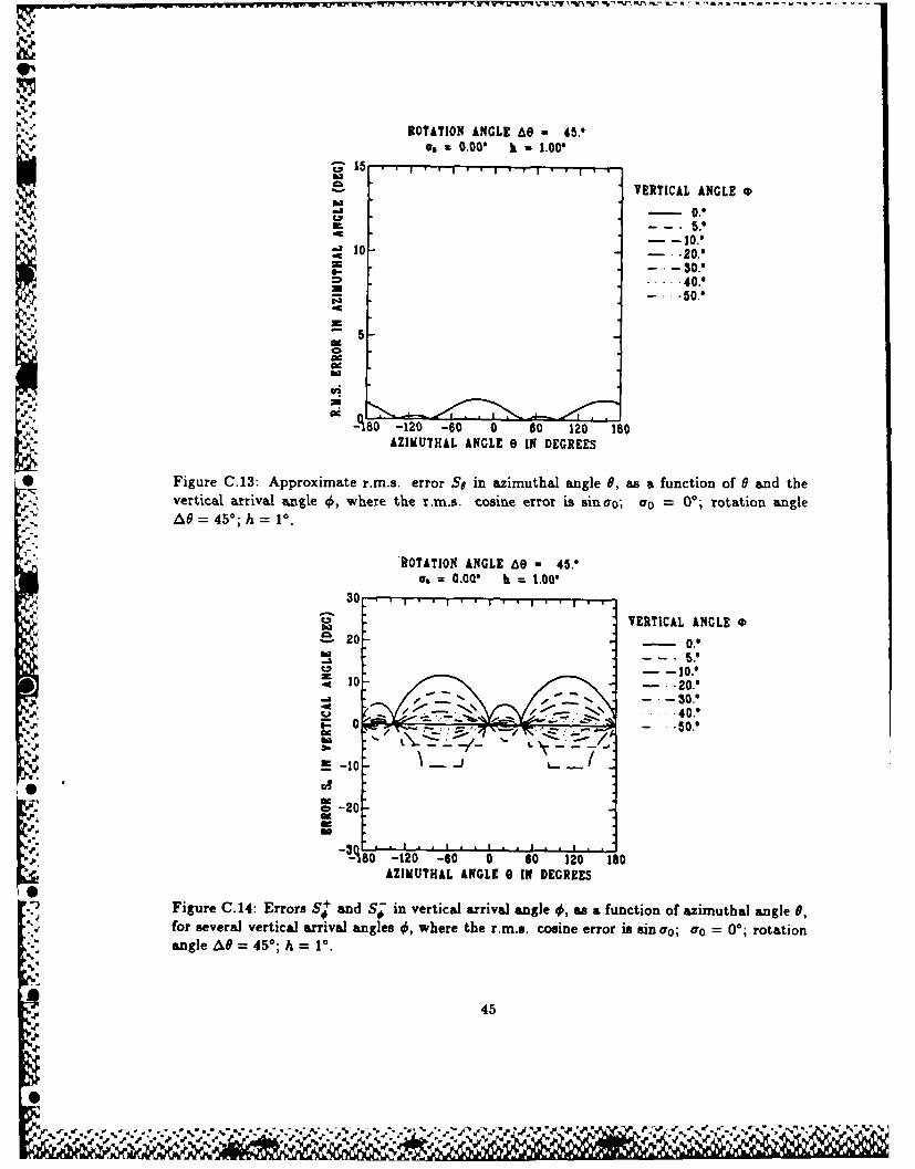
* Figure C.13: Approximate r.m.s. error So in azimuthal angle 0, as a function of 0 and thevertical arrival angle 4, where the r.m.s. cosine error is sinao; co = 00; rotation angleA = 45';h= ° .
'ROTATION ANGLE 60 - 45"=: 000' = 1.00
30.
VERTICAL ANGLE 0P
-20O.
< I 0 l .2 0 . 9
- -30...... 40.'0 I TZ . . .
t1' 0-120 -20 180AZIMUTHAL ANGLE 0 IN DEGREES
Figure C.14: Errors S' and S in vertical arrival angle 0, as a function of azimuthal angle 9,for several vertical arrival angles q$, where the r.m.s. cosine error is sin Oro; Oro = 00; rotationangle A# = 45*; h 1=0.
45
- \ •Jg . " ' ,-- o.L -
• S
,j,,,, S.

ROTATION ANGLE 6e - 9.
U.=0.00* b - 1.00*q~15
S VERTICAL ANGLE 0s
10- 2 .
.. . 40.0- ~ - 0.*
5
Cfi
-A80 -120 -60 0 60 120 180AZIMUTHAL ANGLE 0 IN DEGREES
Figure C.15: Approximate r.m.s. error S# in azimuthal angle 0, as a function of 6 and thevertical arrival angle 4,where the r.rn.s. cosine error is sin ao; o 00; rotation angle
A8 9'; h 1'.
ROTATION ANGLE 60 90.'
30VERTICAL ANGLE 0
S 20-- 0hi --. 5.0
-30.
0 - 20.
M-10 - S.
C, 20
r
-O-120 -60 0 60 120 1000. AZIMUTHAL ANGLE 0 IN DEGREES
L **,~Figure C.16: Errors S+and S-7 in vertical arrival angle 4,, as a function of azimuthal angle 6,for several vertical arrival angles 4,where the r.m.s. cosine error is sin Oro; fo= 00; rotation
angle AV=90*; h 1'.
46
~ q.5*

ROTATION ANGLE A0O - 135.'e.=0.00* h =1.00*
15
VERTICAL ANGLE
5.*
10 - -20.'
40.*
-50.
A C.
A80lS -120 -60 0 60 120 180AZIMUTHAL INGLE 8 IN DEGREES
Figure C.17: Approximate r.m.s. error S# in azimuthal angle 0, as a function of 6 and thevertical arrival angle 4,, where the r.m.s. cosine error is sin Go; aro = 00; rotation angle
AO 135w; h P1.
ROTATION ANGLE 69 - 135.'C,=0.00. h =1.00'
30.S VERTICAL ANGLE 0
-- 10.'10 - -20.0
- -S.' -- 30.'
- ,-.---~ -40.0
-1201 -60 0 60 120' 180AZIMUTHAL ANGLE e IN DEGREES
Figure C.18: Errors S'and S-in vertical arrival angle 4,, as a function of azimuthal angle 0,for several vertical arrival angles , where the r.m.s. cosine error is sin ao; a0 00; rotationangle AO 135*; h 1.
47
% * %~ %" "

o1
I-."
-
"
y..
'%
.•
0'"
e'p
* * , , .4 - . tS *S t
* * -.
.
.h
.~ d

UNCLASSI FIED
SECURITY CLASSIFICATION OF FORM
(highest Classificationt of Title, Abstract. Keywords)
DOCUMENT CONTROL DATAISecurily claselficattion of title. body of abstract aind indexing efnotation must be enlered when the overall locurment i$s l d,o)
1. ORIGINATOR (the name and address of the orgarnization preparing the document 2. SECURITY CLASSIFICATIONOrganizations for whom the document was prepared, e.g. Establishment sponsoring (overall security classification of the documenta contractor's report, or tasking agency, are entered in section 8.) including special warning terms if applicabie)
Defence Research Establishment Atlantic Unclassified
3. TITLE (the complete document title as indicated on the title page. Its classification should b? indicated by the appropriateabbreviation (M.C.R or U) in parentheses after the title.)ESTIMATION OF AZIMUTHAL AND VERTICAL ARRIVAL ANGLES AT A ROTATABLE HORIZONTALLINE ARRAY (U)
4. AUTHORS (Last name, first name, middle initial. If military, show rank, e.g. Doe, Mal. John E.)
TRENHOLM, B. A. and THERIAULT, .Jh'mes A.
"5. DATE OF PUBLICATION tmonth an~d year of publication of 6a. NO, OF PAGES (total 6b NO OF REFS (reit citet: ind.. ocument) containi g information. Include document)
- JUL 1987Annexes. Appendices, etc.)" .-5 3 2
7- DESCRIPTIVE NOTES (the category of the document, e.g technical report, technical note or memorandum If appropriate. enter the type of* report. e.g interim, progress, summary, annual or final Give the inclusive daltes when a specific reporting period is covered)
DREA Report
B SPONSORING ACTIVITY (the name of the department prolect office or Laboratory sponsoring the research and deveiopment Include theaddress.)
Defence Research Establishment Atlantic, P.O. Box 1012, Dartmouth, N.S. B2Y 3Z7
* 9a PROJECT OR GRANT NO. (if appropriate, the applicable research 9c. CONRACT NO (it appropriate. the apphcable numbe, underand development project or grant number under which the document which the document was written)
%% was written. Please specify whether project or grant)
".4 Research Project DRDA06
iCa ORIGINATOR'S DOCUMENT NUMBER (the official document 10b. OTHER DOCUMENT NOS. (Any other numbers which Maynumber by which the document is identified by the originating be assigned this document either by the originator or by theactivity This number must be unique to this document.) aponsor)
DREA REPORT 87/101
1 1. DOCUMENT AVAILABILITY (aty limitations on further dissemination of the document, other ti-, those imposed by security clesslic0rion)
IX I Unlimited distributionI Distribution limited to defence departments and defence contractors; further distribution only as approved
i Distribution limited to defence departments and Canadian defence contractors: further distribution only as approvedI I Distribution limited to government departments and agencies; further distribution only as approved
I Distribution limited to defence departments; further distribution only as approvedI ) Other (please specify):
12. DOCUMENT ANNOUNCEMENT (any limitation to the bibliographic announcement of this document. This will normally correspond tothe Document Avalablty (11). However, where further distribution (beyond the audience specified in 11) is possible, a widerannouncement audience may be selected.)
Unlimited Distribution
UNCLASSIFIED
SECURITY CLASSIFICATION OF FORM
49 oC03 9/04/87
0%' - •. . .- , -. .•-%-%"%"%-.." .%-% % - %"%,). - - .,. % '% % - - - % % . - - . - - - • . . " -* - .. ". -.V..%

[" '-: UNC LASS IF I EDSECURITY CLASSIFICATION OF FORM
13. ABSTRACT I a brief and factual summary of the document. It may also appear elsewhere in the body of the document itself it is highlydesrabe that the miostract of classified documents be unclassified. Each paragraph of the abstract shall begin with an indication of thesecurity classification of the information in the paragraph (unless the document Itself is unclassified) represented as (S). IC), IRi. or 11U)ft is not necessary to include here abstracts in both official languages unless the text is bilingual
A Horizontal Line Array (HLA) receiver is subject to left-right bearing
ambiguity. It is also susceptible to bearing bias caused by non-zero vertical
arrival angles. The true bearing angle and the vertical arrival angle may both be
estimated if a second observation is made, with the HLA rotated to a neworientation.
A closed-form solution is presented for the case of stationary source and receiver.
For small observation errors, the resulting errors in the estimated angles can also
be expressed in closed form.
..
14 KEYW'AORDS. DESCRIPTORS or IDENTIFIERS Itechnically meaningful terms or short phrases that characterite a document and could be- heipful in cataloguing the document They should be selected so that no security classification is required. Identifiers. such as equipment
model designat on, trade name, military project code name, geographic location may also be included If possible, keywords should be selectedfrom a publisled thesaurus e.g. Thesaurus of Engineering and Scientific Terms (TEST) and that thesaurus identified. If it is not possible tcselect indexing terms which are Unclassified, %he classfication of each should be indicated as with the title.)
Underwater Acoustics
Beamform i ng
Antenna
Ambiguity
Signal Processing
.-.,
Ii-
_%-.
UNCLASSIFIED
SECURITY CLASSIFICATION OF FORM
50
- % %,°, ". %

pAt
pled
'IIISiiII'l II'k
JvL