effect of a baffle length
TRANSCRIPT

7/27/2019 Effect of a Baffle Length
http://slidepdf.com/reader/full/effect-of-a-baffle-length 1/18

7/27/2019 Effect of a Baffle Length
http://slidepdf.com/reader/full/effect-of-a-baffle-length 2/18
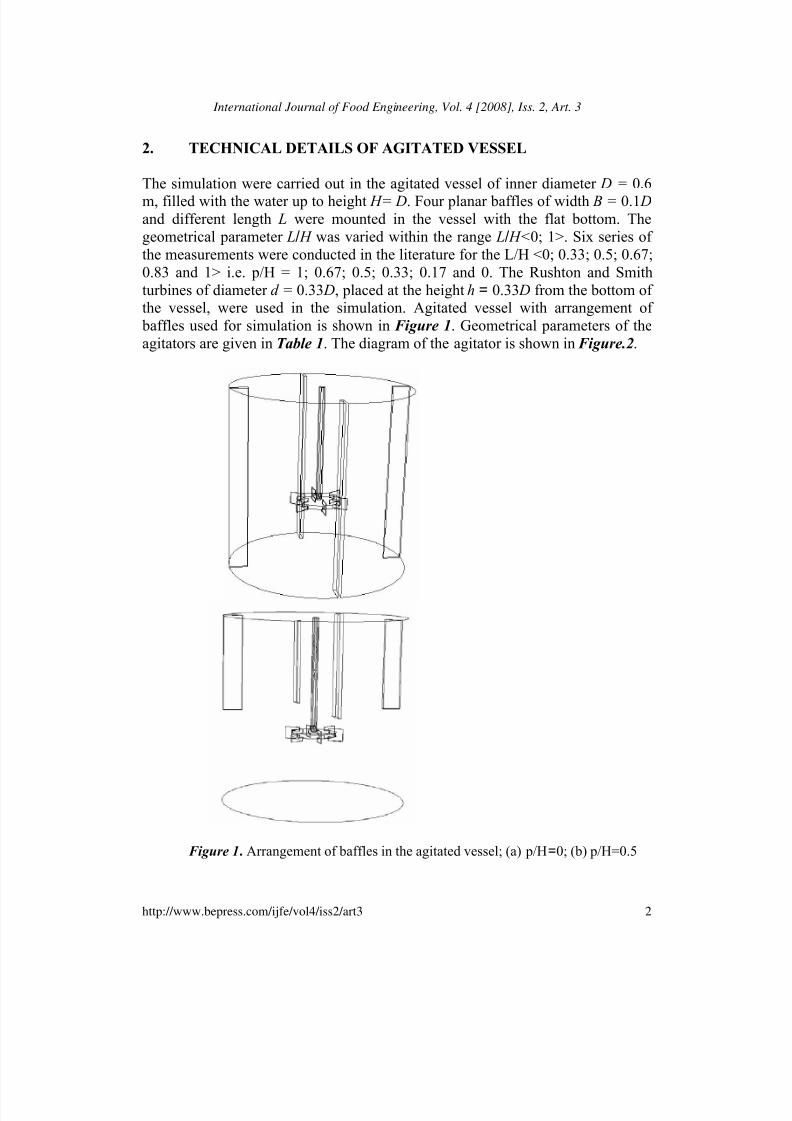
Simulation of an Effect of a Baffle Length on
the Power Consumption in an Agitated Vessel
Palani Sivashanmugam and S. Prabhakaran
Abstract
Agitated vessels are often used for homogenization of the miscible liquids in chemical, bio-
chemical, and food industries. Computational fluid dynamics (CFD) is a useful tool for studying
fluid flows, including those of mixing systems. It is particularly powerful where the ability existsto corroborate model results with available data. The CFD simulation was carried out for Rushton
and Smith turbines agitators. The standard k- model has been used for turbulence modeling. The
data obtained by simulation are matching with the literature experimental value for standard baffle
with the discrepancy of less than + 4.5% for power number. The simulated results for agitated
vessel with short baffle (non-standard) are agreeing with the literature values within plus or minus
5% for Power Number.
KEYWORDS: agitated vessel, power consumption, short baffles, CFD, turbine agitators

7/27/2019 Effect of a Baffle Length
http://slidepdf.com/reader/full/effect-of-a-baffle-length 3/18
1. INTRODUCTION
Agitators are used widely for mixing of miscible and immiscible fluid, dispersion
of gas in liquid, suspension of solids in liquid as it is done in hydrogenation of oils. Various types of agitators are used for different applications of mixing and
agitation. Among these turbine type agitator is used widely for dispersing gasinto liquid, which is very much required in fermentation and effluent treatment
application. Prior to 1970s, researchers recognized that the angle of impeller
blade, vessel geometry, baffle were plays the major role in agitated vessel and
postulated that an impeller with more baffle can perform better in terms of power consumption. Since then, impellers with angle of blades have been discarded, and
the 6-blade disk turbine impeller with 4- baffle has become the most popular
impeller.The power consumption depends on the geometrical parameters of the
agitator, baffles and vessel. The power curves for different agitators working inthe vessel equipped with standard baffles (i.e. baffle length L is equal to liquidheight H in the vessel) were reported by Joanna Karcz, Marta Major, 1998.
During recent years, the studies on power consumption for the impeller-vessel
systems of different geometry have been continued by many research workers.
Using CFD, one can understand the mechanism of mixing of fluids in mixingtanks with much easier and economical than the use of experiments. Also CFD
simulation is useful for predicting the vessel hydrodynamics in a wide range of
operational conditions or various geometries. Computational Fluid Dynamics(CFD) has already been used in many studies to predict flow patterns and local
gas volume fractions in the stirred gas-liquid vessels (Bakker and Van Den
Akker,1994; Morud and Hjertager,1996; Derksen, 2002; Van Den Akker, 2007).CFD has reached a level that gives reliable and accurate results for predicting the
flow field in stirred vessels (Sommerfeld and Decker,2003). Several methods had been successfully developed to simulate the flow in a stirred vessel, where good
agreement of the mean flow field with experimental data was achieved. Three-
dimensional steady-state predictions based on this approach were presented byVlaev, and. Staykov, 2001. Mavros and Mann extended this approach to simulate
two-phase flow in a Rushton stirred vessel.
This paper presents the simulation results of an effect of a baffle length on
the power consumption in the agitated vessel with different high-speed agitatorsand the results were compared with the experimentally reported literature value.
1
Sivashanmugam and Prabhakaran: Simulation of an Effect of a Baffle Length on the Power Consumption in an Agitated Vessel
Published by The Berkeley Electronic Press, 2008
7/27/2019 Effect of a Baffle Length
http://slidepdf.com/reader/full/effect-of-a-baffle-length 4/18

7/27/2019 Effect of a Baffle Length
http://slidepdf.com/reader/full/effect-of-a-baffle-length 5/18
Table 1. Geometrical parameters of the agitators
No Agitator d/D Z a/d b/d Remarks
1 Rushton
Turbine
0.33 6 0.25 0.2
2 Smith Turbine 0.33 6 0.25 0.2 R = b/2
(a) Rushton turbine
(b) Smith turbine
Figure 2. Diagram of agitators
3. CFD SIMULATION METHODS
Three main generalized approaches namely multiple reference frame (MRF),
computational snapshot, and sliding mesh approach are used to predict the flow
field in an agitated vessel. The first two approaches involve steady state
computation producing time average flow filed and the third involves transientcomputation to produce time accurate flow filed. The computational domain
3
Sivashanmugam and Prabhakaran: Simulation of an Effect of a Baffle Length on the Power Consumption in an Agitated Vessel
Published by The Berkeley Electronic Press, 2008

7/27/2019 Effect of a Baffle Length
http://slidepdf.com/reader/full/effect-of-a-baffle-length 6/18
representing mixer is divided into two non-overlapping regions –one surrounding
the impeller and the other representing the rest of the vessel. In this paper MRF
approach has been tried. The brief description of this approach is as follows:
initially simulation of flow is done for inner domain surrounding the impeller in areference frame rotating with impeller. The flow field separating (interface) the
inner and outer domain serves as boundary conditions for simulation of flow fieldin the outer domain of the frame reference model. This results in the revised
boundary conditions for flow field inner domain. The procedure is repeated till
suitable numerical convergence criterion is achieved.
CFD simulation can be carried out by solution of continuity equation andtime averaged Navier-stroke equations;
{ } 0ρdiv =U (1)
{ } { } { } { } .u'u'ρdivµdiv pρdivρt
FUUUU +−+∇+−∇=+∂∂
(2)
Several turbulence models such as k-epsilon, k-omega, etc are availablefor carrying out simulation. Among these models k-epsilon is very widely used
because of its reasonable accuracy for a wide range of turbulent condition in an
agitated vessel. The following two equations have to be solved along with the
above equation for k-ε turbulence model.
{ } { } ρε2µk σk"
µdivk ρdivρk
tij1
1−+
∇=+
∂∂
EU (3)
{ } { }k
ερC-2µ
k
εCε
σε
µdivερdivρε
t
2
2εijij11ε1
EEU ×+
∇=+
∂∂ (4)
Where
∂∂
+∂∂
=i
j
j
ii
xx2
1 jE
UU(5)
Solution of Eqs (3) and (4) give spatial variation of k and ε which in turn
can be used to find out spatial variation of turbulent viscosity or eddy viscosity µ t using the Prandtl-Kolmogorov relation
ε
k ρCµ
2
µt = (6)
Once µ t is known, expression of turbulent stresses appearing in Eq.(2)can be given as
ijijt ji ρk δ3
22µu'u'ρ −=− E (7)
4
International Journal of Food Engineering, Vol. 4 [2008], Iss. 2, Art. 3
http://www.bepress.com/ijfe/vol4/iss2/art3

7/27/2019 Effect of a Baffle Length
http://slidepdf.com/reader/full/effect-of-a-baffle-length 7/18
The standard values of different constants appearing in Eqs (3),(4) and (6)
are C µ = 0.09, σk =1.00, σε = 1.3, C 1ε =1.44 and C 2ε =1.92Commercial CFD software FLUENT was used to perform simulation. To
start with several exploratory simulations were carried out using MRF approach
to finalize the geometry and to conduct grid independent test and the result isshown in Figure 3. From this figure it is observed that accuracy of the result
increases with increase in mesh (cell) volume and became constant at 176550
cells. Final CFD simulations were done at this cell number. Figure 4 presents thetypical appearance of the vessel with meshed condition.
Mesh volume Vs Power Number
0
2
4
6
0 200000 400000 600000 800000 1E+06 1E+06
Mesh Volume
P o w e r N u m b e r
Figure 3. Effect of mesh volume number on simulated power number
Figure 4. Diagram of the meshed agitated vessel
5
Sivashanmugam and Prabhakaran: Simulation of an Effect of a Baffle Length on the Power Consumption in an Agitated Vessel
Published by The Berkeley Electronic Press, 2008

7/27/2019 Effect of a Baffle Length
http://slidepdf.com/reader/full/effect-of-a-baffle-length 8/18

7/27/2019 Effect of a Baffle Length
http://slidepdf.com/reader/full/effect-of-a-baffle-length 9/18
Figure 5. Simulated and Experimental power
Number for Rushton Turbine p/H=0
0
1
2
3
4
5
6
7
10000 100000 1000000
Reynolds Number
P o w e r N u m b e r
Simulation value
literature Value
Figure 6. Simulated and Experimental power
number for smith turbine p/H= 0
0
1
2
3
4
5
6
10000 100000 1000000
Reynolds Number
P o w
e r N u m b e r
Simulation Value
:iterature Value
7
Sivashanmugam and Prabhakaran: Simulation of an Effect of a Baffle Length on the Power Consumption in an Agitated Vessel
Published by The Berkeley Electronic Press, 2008
7/27/2019 Effect of a Baffle Length
http://slidepdf.com/reader/full/effect-of-a-baffle-length 10/18
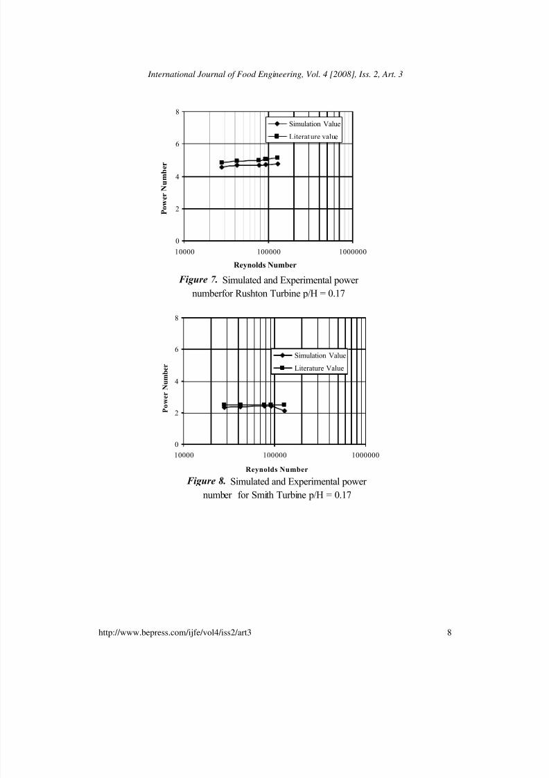
Figure 7. Simulated and Experimental power
numberfor Rushton Turbine p/H = 0.17
0
2
4
6
8
10000 100000 1000000
Reynolds Number
P o w e r N u m b e r
Simulation Value
Literature value
Figure 8. Simulated and Experimental power
number for Smith Turbine p/H = 0.17
0
2
4
6
8
10000 100000 1000000
Reynolds Number
P o w e r N u m b e r
Simulation Value
Literature Value
8
International Journal of Food Engineering, Vol. 4 [2008], Iss. 2, Art. 3
http://www.bepress.com/ijfe/vol4/iss2/art3

7/27/2019 Effect of a Baffle Length
http://slidepdf.com/reader/full/effect-of-a-baffle-length 11/18
Figure 9. Simulated and Experimental power number for Rushton Turbine p/H = 0.33
0
2
4
6
8
10000 100000 1000000
Reynolds Number
P o w e r N u m b e r
Simulation Value
Literature Value
Figure 10. Simulated and Experimental power
number for Smith Turbine p/H = 0.33
0
2
4
6
8
10000 100000 1000000
Reynolds Number
P o w e r N u m b e r
Simulation Value
Literature value
9
Sivashanmugam and Prabhakaran: Simulation of an Effect of a Baffle Length on the Power Consumption in an Agitated Vessel
Published by The Berkeley Electronic Press, 2008

7/27/2019 Effect of a Baffle Length
http://slidepdf.com/reader/full/effect-of-a-baffle-length 12/18
Figure 11. Simulated and Experimental power
number for Rushton Turbine p/H = 0.5
0
2
4
6
8
10000 100000 1000000
Reynolds Number
P o w e r N u b e r
Simulation Value
Literature value
Figure 12. Simulated and Experimental power
nmuber for Smith Turbine p/H = 0.5
0
2
4
6
8
10000 100000 1000000
Reynolds Number
P o
w e r N u m b e r
Simulation value
Literature value
10
International Journal of Food Engineering, Vol. 4 [2008], Iss. 2, Art. 3
http://www.bepress.com/ijfe/vol4/iss2/art3

7/27/2019 Effect of a Baffle Length
http://slidepdf.com/reader/full/effect-of-a-baffle-length 13/18
Figure13. Simulated and Experimental power number for Rushton Turbine p/H = 0.67
0
2
4
6
8
10000 100000 1000000
Reynolds Number
P o w e r N u m b e r
Simulation Result
Literature Value
Figure 14. Simulated and Experimental power
number for Smith Turbine p/H = 0.67
0
2
4
6
8
10000 100000 1000000
Reynolds Number
P o w e r N u m b e r
Simulation value
Literature Value
11
Sivashanmugam and Prabhakaran: Simulation of an Effect of a Baffle Length on the Power Consumption in an Agitated Vessel
Published by The Berkeley Electronic Press, 2008

7/27/2019 Effect of a Baffle Length
http://slidepdf.com/reader/full/effect-of-a-baffle-length 14/18
Figure 15. Simulated and Experimental
power number for Rushton Turbine p/H = 1
0
2
4
6
8
10000 100000 1000000
Reynolds Number
P o w e r N u b e r
Simulation Result
Literature value
12
International Journal of Food Engineering, Vol. 4 [2008], Iss. 2, Art. 3
http://www.bepress.com/ijfe/vol4/iss2/art3

7/27/2019 Effect of a Baffle Length
http://slidepdf.com/reader/full/effect-of-a-baffle-length 15/18
a)
b)
Figure 16 . Radial velocity for Rushton turbine (a) p/H = 0, and
Turbulent Kinetic energy for Rushton Turbine (b) p/H = 0
13
Sivashanmugam and Prabhakaran: Simulation of an Effect of a Baffle Length on the Power Consumption in an Agitated Vessel
Published by The Berkeley Electronic Press, 2008

7/27/2019 Effect of a Baffle Length
http://slidepdf.com/reader/full/effect-of-a-baffle-length 16/18
c)
d)
Figure 16 . Radial velocity for Rushton turbine (c) p/H = 0.5, and
Turbulent Kinetic energy for Rushton Turbine, (d) p/H = 0.5
14
International Journal of Food Engineering, Vol. 4 [2008], Iss. 2, Art. 3
http://www.bepress.com/ijfe/vol4/iss2/art3

7/27/2019 Effect of a Baffle Length
http://slidepdf.com/reader/full/effect-of-a-baffle-length 17/18
5. CONCLUSION
CFD simulation for the power consumption in agitator vessel with varying bafflelength p/H = 1; 0.67; 0.5; 0.33; 0.17 and 0 in turbulent flow conditions has been
explained in this paper using Fluent version 6.2.16. The data obtained bysimulation are matching with the literature experimental value for standard baffle
with the discrepancy of less than ±4.5% for power number. The simulated resultsfor agitated vessel with short baffle (non-standard) are agreeing with the literature
values within plus or minus 5% for power number. The reason for reduced power
consumption in nonstandard baffle has been evidenced from more uniformdistribution of turbulent kinetic energy both in radial and axial direction as
observed from turbulent kinetic energy distribution profile around the turbine
agitator.
NOMENCLATURE
a length of the agitator blade, m B width of the baffles, m
b width of the agitator blade, m
D inner diameter of the agitated vessel, m
d diameter of the agitator, m
H liquid height in the vessel, m
h distance between agitator and bottom of the vessel, m
J number of baffles
k specific turbulent kinetic energy, m2/s L length of the baffle, m
n agitator speed, s-1
P power consumption, W
Power number = P / n3 d
5 ρ
Reynolds number = n d 2ρ/ µ
p distance between lower edge of the baffle and bottom of the vessel, m R radius of the agitator blade, m
Z number of agitator bladeGreek letter
ε specific turbulent energy dissipation rate, m2/s
µ dynamic viscosity of the liquid, kg/ms
µ t turbulent viscosity or eddy viscosity , kg/msρ liquid density, kg
15
Sivashanmugam and Prabhakaran: Simulation of an Effect of a Baffle Length on the Power Consumption in an Agitated Vessel
Published by The Berkeley Electronic Press, 2008

7/27/2019 Effect of a Baffle Length
http://slidepdf.com/reader/full/effect-of-a-baffle-length 18/18
REFERENCES
1. Joanna Karcz *, Marta Major ”An Effect of a Baffle Length on the Power
Consumption in an Agitated Vessel” Chemical Engineering and Processing,1998, 37 249–256.
2. Bakker, A., Van Den Akker., H.E.A., “A computational model for the gas-
liquid flow in stirred reactors”, Trans. IchemE , 1994, A72, 594-606.
3. Morud, K.E., Hjertager, B.H., LDA, “Measurements and CFD modeling of gas-
liquid flow in a stirred vessel”, Chem. Eng. Sci, 1996, 51(2), 233-249.
4. Derksen, J.J., Venneker, B.C.H., Van Den Akker, H.E.A., “Population balance
modeling of aerated stirred vessels based on CFD”,2002, AIChE J , 48(4), 673-
685.
5. Van Den Akker., H.E.A.,“ The details of turbulent mixing process and their
simulation”, Advances in Chemical Engineering,2006, 31,151-229.
6. Sommerfeld, M., Decker, S. “State of the art trends in CFD simulation of
stirred vessels”, Proceedings of the 11th European Conference on Mixing ,
Bamberg , 2003.p. 1
7. Vlaev, S.D., P. Staykov, R. Mann, H. Hristov and P. Mavros, “Experimental
and CFD Characterization of a New Energy-saving Mixing Impeller for the
Process Industries”, Paper presented at 18th North American Mixing Conference, Pocono Manor , PA, 2001,June 24-29.
8. Mavros, P., R. Mann, S.D. Vlaev and J. Bertrand, “Experimental Visualization
and CFD Simulation of Flow Patterns Induced by a Novel Energy-Saving
Dual-Configuration Impeller in Stirred Vessels”, Trans. I. Chem. E ,2001,79A, 857–866.
16
International Journal of Food Engineering, Vol. 4 [2008], Iss. 2, Art. 3
http://www.bepress.com/ijfe/vol4/iss2/art3