edinburgh research explorer · and technology, industrial estate ... heriot-watt university,...
TRANSCRIPT

Edinburgh Research Explorer
Facile hydrothermal synthesis of economically viable VO2(M1)counter electrode for dye sensitized solar cells
Citation for published version:Mutta, GR, Popuri, SR, Vasundhara, M, Maciejczyk, M, Racu, AV, Banica, R, Robertson, N, Wilson, JI &Bennett, NS 2016, 'Facile hydrothermal synthesis of economically viable VO2(M1) counter electrode for dyesensitized solar cells' Materials research bulletin, vol 83, pp. 135-140. DOI:10.1016/j.materresbull.2016.05.027
Digital Object Identifier (DOI):10.1016/j.materresbull.2016.05.027
Link:Link to publication record in Edinburgh Research Explorer
Document Version:Peer reviewed version
Published In:Materials research bulletin
General rightsCopyright for the publications made accessible via the Edinburgh Research Explorer is retained by the author(s)and / or other copyright owners and it is a condition of accessing these publications that users recognise andabide by the legal requirements associated with these rights.
Take down policyThe University of Edinburgh has made every reasonable effort to ensure that Edinburgh Research Explorercontent complies with UK legislation. If you believe that the public display of this file breaches copyright pleasecontact [email protected] providing details, and we will remove access to the work immediately andinvestigate your claim.
Download date: 22. Jul. 2018
1
Facile hydrothermal synthesis of economically viable VO2(M1) counter electrode for dye sensitized solar cells Geeta R. Mutta1*, Srinivasa R. Popuri2, M. Vasundhara3, Michal Maciejczyk4, Andrei V. Racu5, Radu Banica5, Neil Robertson4, John I. B. Wilson6, Nick S. Bennett1
1Nano-Materials Laboratory, School of Engineering and Physical Sciences, Heriot-Watt
University, Edinburgh EH14 4AS, United Kingdom 2Institute of Chemical Sciences, School of Engineering and Physical Sciences, Heriot-Watt
University, Edinburgh EH14 4AS, United Kingdom 3Materials Science and Technology Division, CSIR-National Institute for Interdisciplinary Science
and Technology, Industrial Estate, Trivandrum 695019, India 4School of Chemistry and EaStCHEM, University of Edinburgh, Edinburgh EH9 3FJ, United
Kingdom 5National Institute for Research and Development in Electrochemistry and Condensed Matter, Dr.
A. Paunescu Podeanu str. 144, Timisoara, Romania 6Institute of Photonics and Quantum Sciences, School of Engineering and Physical Sciences,
Heriot-Watt University, Edinburgh EH14 4AS, United Kingdom *Corresponding author: [email protected]
Abstract
In this study, we focus at reducing the fabrication cost of dye sensitized solar cells (DSSCs).
Sphere-like VO2(M1) polymorph was synthesized by single step facile hydrothermal approach
using citric acid as the reducing agent. Phase purity, charge state and surface morphology of the
synthesized product was confirmed by X-ray diffraction, X-ray photoelectron spectroscopy and
scanning electron microscopy respectively. The electrochemical impedance and cyclic
voltammograms of VO2 films indicated a good electrocatalytic activity towards redox reaction of
the I-/I3- shuttle. Owing to the low cost, low-temperature processing and good catalytic activity,
in this work we propose to use VO2 as a counter electrode to substitute the expensive platinum
2
electrode in DSSCs. By means of VO2 based DSSCs we achieved a fivefold reduction in the cost
to energy conversion efficiency ratio. It is expected that with further optimization, VO2 can be
exploited as a good candidate for counter electrode in DSSC technology.
Keywords: A. layered compounds; B. oxides; C. chemical synthesis; D. impedance
spectroscopy; E. catalytic properties
1. Introduction
Draining of natural resources is bringing a global energy crisis, ever closer yet solutions
are possible such as a shift to renewable energy sources. Solar energy is the largest natural
energy resource which can be explored and utilized much more generously [1]. Dye sensitized
solar cells (DSSCs) technology which convert light into electricity has gained a lot of attention
due to their key features such as low fabrication cost, environmental compatibility, price-to-
performance ratio, ability to work at wider angles and in low light [2,3]. A typical DSSC consists
of a metal oxide as an active electrode, a light harvesting dye, a redox electrolyte and a counter
electrode (CE). The chief concern in the commercialization of DSSCs is cutting down the
manufacturing cost further, while keeping up decent efficiencies and lifetime. The principle
production cost of DSSCs depends on the materials cost and fabrication process. The CE is a
vital component which transfers the electrons from the external circuit to the internal electrolyte
and as a whole, reduces the tri-iodide ions to iodine ions, which eventually realizes the operation
of DSSCs.
Conventionally, platinum (Pt) on fluorine doped tin oxide (FTO) coated glass is used as a
CE. Platinum is chosen because of its high electrocatalytic activity, conductivity and chemical
affinity to reduce tri-iodide [4]. However, the major concern here is, Pt being expensive and
having limited natural availability which primarily restricts the production of DSSCs at large
3
scale. Hence, there is a pressing need for the identification of economically viable CE materials,
exhibiting high photovoltaic performance and stability. Thus many researchers have been
focusing on alternative materials to Pt with similar characteristics. In the recent years, the
number of reports concerning the alternative CEs has increased significantly. For the current
state of art of Pt-free CEs, the reader may refer to review papers elsewhere [4-9]. Apart from
high catalytic activity and high electrical conductivity, the prime characteristics for choosing an
alternative material for CEs are abundance in nature, environmentally friendly, stability and
economic viability for large scale production.
Transitional metal oxides (TMOs) are of particular interest for this type of application,
because of their excellent atmospheric stability, low cost, abundance in nature, good catalytic
and electrical conductivities. Despite these advantages less effort has been devoted to exploit
TMOs as CEs until this decade. Recently TMOs such as WO2, WO3, ZrO2, TiO2, Cr2O3, MoO2,
Nb2O5, NiO, V2O5 and V2O3 are reported as CEs in electrolyte based DSSCs and V2O5 composite
in solid state DSSCs [10-15]. In TMOs family, vanadium based oxides are receiving huge
interest in the field of energy storage technologies such as batteries and super capacitors, because
of their diverse chemical motifs, layered structure, high energy capacity and moderate work
functions [16,17]. From the economical point of view, the raw materials cost of vanadium based
oxides estimated from Sigma-Aldrich catalogue show 30 times less than that of Pt of the same
purity level. The VO2 compound exhibits several stable polymorphs such as VO2(M1), VO2(R),
VO2(B), VO2(A), VO2(D), VO2(BCC) and VO2(N) [18]. In particular the VO2(M1) polymorph
has attracted tremendous attention for electronic, thermochromic and optical applications such as
smart windows and electrical switches [19-21]. In this work, we propose and demonstrate
VO2(M1) to be used as a CE in DSSCs.
4
To the best of our knowledge, it is the first time that VO2(M1) has been explored as a CE
in DSSC technology. We report here a simple hydrothermal route to synthesize the pure
VO2(M1) polymorph. We have carried out detailed characterization of synthesized product and
investigated the photovoltaic performance for VO2(M1) CEs in DSSCs.
2. Experimental
2.1. Materials synthesis
The synthesis of VO2(M1) via a hydrothermal process is as follows: Initially V2O5
(Aldrich) was dissolved in 35 mL of deionized water. After stirring for 15 min using a magnetic
stirrer, 1.5 molar ratio to V2O5 of citric acid monohydrate (C6H8O7·H2O; Merck) was added into
the solution and stirring was prolonged for another 15 min. The resultant yellowish green
aqueous solution was transferred into the Teflon lined stainless steel autoclave. The sealed steel
autoclave was placed in a high temperature oven at 250 °C. After 24 hrs, the autoclave was
slowly cooled to room temperature naturally. The as obtained bluish-black powder samples were
filtered and washed several times with distilled water and ethanol to remove unreacted chemical
species and dried in air at 80 °C for 6 hrs and then used for further characterizations.
2.2. Fabrication of dye sensitized photoelectrodes
The photoelectrodes (PEs) are prepared as follows: first FTO coated glass substrates
(Pilkington TEC glass™, sheet resistance: 11.7 Ω/sq, 2.2 mm in thickness, TEC-12) were cut
into small pieces (2 × 2 cm). The substrates were first cleaned thoroughly with Teknon
microcleanse detergent solution, ultrasonicated in deionised water followed by acetone and iso-
propanol for 15 min at each step, and then dried in flowing nitrogen to further remove any
solvent traces. Afterwards the substrates were transferred into a 40 mM TiCl4 solution container
5
and heated for 1 hour at 80 °C to form a compact layer of TiO2. Later the substrates were rinsed
thoroughly with deionised water followed by dry in flowing nitrogen. Commercial
nanocrystalline TiO2 paste (DSL 18NR-T, Dyesol as the transparent layer) was screen printed on
the compact layered FTO substrates, afterward TiO2 scattered paste (DSL 18NRAO, Dyesol as
the scattering layer) was deposited by screen printing. The active screen printed areas were
approximately 1 cm2. The TiO2 coated films were then successively sintered in ambient on a
hotplate in a series of steps such as at 325 °C for 10 min, at 375 °C for 5 min, at 450 °C for 15
min and at 500 °C for 15 min, and finally were cooled down naturally to room temperature. Later
these electrodes were further treated with 40 mM TiCl4 for 30 min at 80 °C and consequently
sintered at 450 °C for 30 min and then allowed for cooling. As soon as these photoelectrodes
reach 80 °C, these films were subsequently immersed in N719 (Dye-sol) solution and kept in an
air-tight glass container at room temperature under dark and dry conditions for 20 hours. Dye
sensitized photoanodes were rinsed with iso-propanol followed by drying with nitrogen flow at
room temperature.
2.3. Fabrication of counter electrodes
First a small hole was drilled on FTO coated glass substrates using a sand blasting unit,
with a smooth finish given by ending the drilling with a portable glass hole drilling tool. These
drilled FTO substrates were subjected to the same cleaning and drying processes as
aforementioned. A thick viscous paste of VO2 was prepared by mixing 4:1 ratio of
hydrothermally synthesized VO2 powder and ethyl cellulose and by adding few drops of α-
terpineol. This paste was deposited on FTO coated glass by screen printing and later sintered at
450 ºC for 30 mins under inert atmosphere at a heating rate of 5 ⁰C/min to remove the organic
6
binders. Reference electrodes were prepared by depositing Pt on FTO glass substrates by means
of sputtering.
2.4. Photovoltaic cell assembly
The N719 dye sensitized TiO2 PEs and CEs were assembled into a sandwich
configuration with a spacer between the two electrodes. Subsequently the liquid electrolyte
(composed of 0.05 M Iodine, 0.1 M lithium iodine, 0.6 M 1-butyl-3-methylimidazolium iodide
and 0.5 M 4-tertbutyl pyridine in a mixture of acetonitrile and valeronitrile) was injected via
drilled hole into the space between these electrodes. Finally the holes were sealed with a polymer
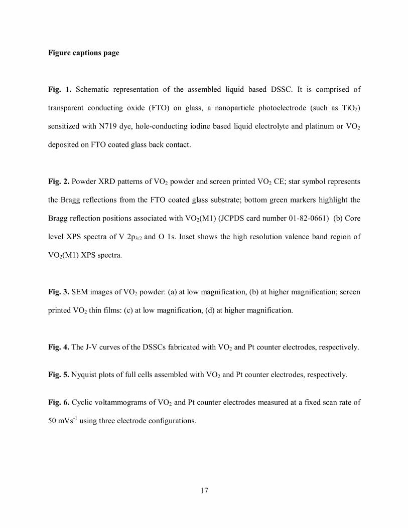
film of 25 μm thickness (Metlonix 1170, Dupont surlyn) and glass cover. The schematic of the
final assembled device is shown in Fig. 1.
2.5. Material and device characterizations
The phase purity and crystallographic structure of VO2 powder was determined using
automated PANalytical X’ Pert Diffractometer, Netherlands (using Ni filtered Cu Kα1 radiation,
λ=1.5406 Å). To further access information about the degree of oxidation of vanadium and
thereby the composition and the electronic structure of VO2, we carried out X-ray photoelectron
spectroscopy (XPS) measurements on powder sample at room temperature. The XPS spectrum
was acquired using a Kratos Analytical AMICUS XPS instrument and a Mg Kα1 X-ray source
operated at 150 W (10 kV, 15 mA). The surface morphology of VO2 powder sample and the
screen printed VO2 CE was investigated by field emission scanning electron microscopy
(FESEM) (XL30 ESEM). The photocurrent density and photovoltage characteristics of DSSCs
were measured by computer controlled digital source meter (Keithley 2400) under AM 1.5 one
sun (100 mWcm-2) illumination using a solar simulator (92250 A, Newport, USA). An
7
electrochemical work station system (Autolab potentiostat equipped with FRA2 module) was
employed to measure the internal resistances of the assembled final cells. Cyclic voltammetry
measurements over the VO2 and Pt CEs were performed at room temperature using a
μAUTOLAB Type III Potentiostat set-up which was driven by the electrochemical software
GPES.
3. Results and discussion
3.1. Structural and morphological characterization
In order to know the phase formation and the crystallinity of the as synthesized powder
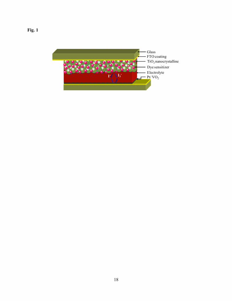
samples, X-ray diffraction (XRD) study was carried out at room temperature. Fig. 2a shows the
XRD patterns of the as-prepared VO2 powder and as well as VO2 CE. For the same XRD
acquisition time, the stronger diffraction peaks observed in the case of CE indicates that thermal
annealing improved the crystallinity. All the diffraction peaks exhibited in the XRD patterns can
be readily assigned to the monoclinic phase of VO2(M1) (JCPDS card no. 01-082-0661). The
room temperature crystal structure details are determined from Le bail fits using the FullProf
program [22]. In the case of powder and thin film samples, the lattice parameters are extracted as
a=5.753(3) Å, b=4.532(3) Å, c=5.364(1) Å, β=122.40(2)º and a=5.7503(4) Å, b=4.5246(3) Å,
c=5.3812(4) Å, β=122.59(2)º respectively. No diffraction peaks corresponding to any other
vanadium oxide phases are detected either in the powder sample or from the screen printed CE.
To further access information about the degree of oxidation of vanadium and thereby the
composition and the electronic structure of VO2, we carried out XPS measurements on powder
sample at room temperature. The XPS spectrum shown in Fig. 2b revealed binding energy levels
that correspond to vanadium and oxygen (which are the chemical elements in VO2) and
atmospheric carbon. No other peaks of impurity elements are noticed. For our XPS analysis, the
8
binding energy (BE) of the adventitious carbon C 1s = 284.6 eV is taken as an energy calibration
reference. Fig. 2b inset shows the valence band (VB) region and core level spectra for vanadium
and oxygen elements in VO2. The high resolution XPS VB region consists of V 3d and O 2p
levels in the energy ranges between 0-2 and 3-9 eV, respectively as shown in the inset of Fig. 2b.
The zero spectral weight at the Fermi level supports the nonmetallic behavior of VO2(M1) at
room temperature. From core level XPS spectra, we noticed the BE levels of V 2p3/2 and O 1s
peaks which are centered at 516.41 eV and 529.84 eV, respectively (see Fig. 2b). These are
characteristic energy levels of the V4+ oxidation state and in good agreement with most of the
reported values. Besides the V4+ 2p3/2 core level one more minor contribution is visible around
517.15 eV. From the literature, it is clear that this BE level corresponds to V5+ 2p3/2 and this
could be due to surface oxidation of the VO2 powder samples [23]. Similarly a second
component is visible in the O 1s signal at 531.2 eV. It can be attributed to surface contamination
by atmospheric carbon. The O 1s BE reported for C=O is within 530.7–531 eV and the extra
shoulder to the O1s peak (531.2 eV) thus falls into the region of C=O O 1s. In addition, this is
also consistent with the components in the C 1s spectrum where we found a shoulder at 287.6
eV, which is a 3.0 eV higher binding energy than the C–C bond (284.6 eV) [24]. Due to a wide
spread in the XPS BE values reported for vanadium oxides, Mendialdua et al. proposed that
difference in binding energies between the O 1s core level and the V 2p3/2 core level (ΔE=
BE(O1s)–BE(V 2p3/2)) is a better determination of vanadium oxidation degree [25]. According to
this, ΔE is between 17.65-17.90 eV, 16.33-18.4 eV, 14.2-14.85 eV, 13.45-14.5 eV and 12.6-12.9
eV for V0, V2+, V3+, V4+ and V5+ oxidization degrees, respectively. In our case, the BE difference
(ΔE) between the vanadium core level (V 2p3/2) and the oxygen core level (O 2p) is 13.65 eV.
9
This is in agreement with +4 oxidation degree of V and confirms the chemical composition as
VO2.
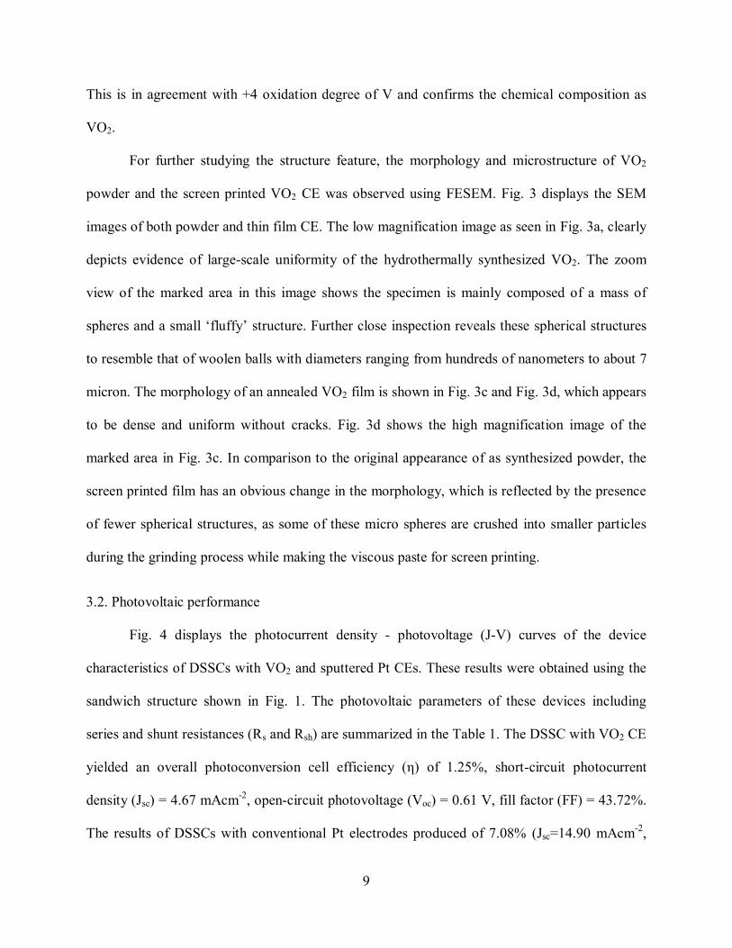
For further studying the structure feature, the morphology and microstructure of VO2
powder and the screen printed VO2 CE was observed using FESEM. Fig. 3 displays the SEM
images of both powder and thin film CE. The low magnification image as seen in Fig. 3a, clearly
depicts evidence of large-scale uniformity of the hydrothermally synthesized VO2. The zoom
view of the marked area in this image shows the specimen is mainly composed of a mass of
spheres and a small ‘fluffy’ structure. Further close inspection reveals these spherical structures
to resemble that of woolen balls with diameters ranging from hundreds of nanometers to about 7
micron. The morphology of an annealed VO2 film is shown in Fig. 3c and Fig. 3d, which appears
to be dense and uniform without cracks. Fig. 3d shows the high magnification image of the
marked area in Fig. 3c. In comparison to the original appearance of as synthesized powder, the
screen printed film has an obvious change in the morphology, which is reflected by the presence
of fewer spherical structures, as some of these micro spheres are crushed into smaller particles
during the grinding process while making the viscous paste for screen printing.
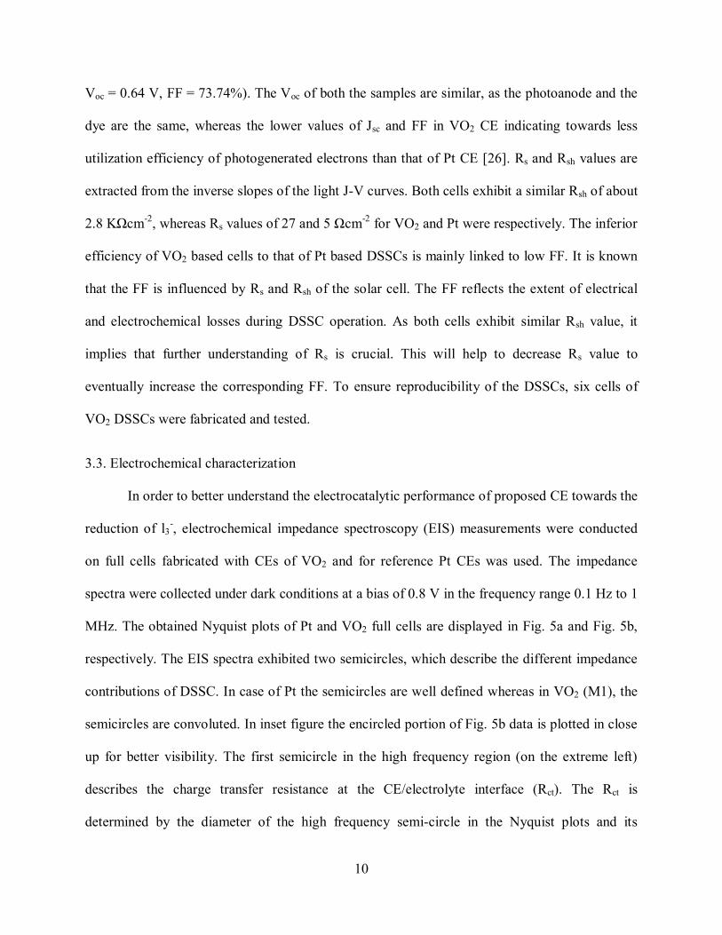
3.2. Photovoltaic performance
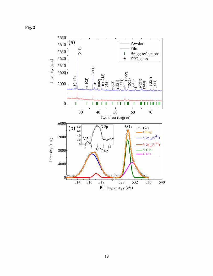
Fig. 4 displays the photocurrent density - photovoltage (J-V) curves of the device
characteristics of DSSCs with VO2 and sputtered Pt CEs. These results were obtained using the
sandwich structure shown in Fig. 1. The photovoltaic parameters of these devices including
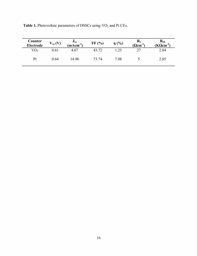
series and shunt resistances (Rs and Rsh) are summarized in the Table 1. The DSSC with VO2 CE
yielded an overall photoconversion cell efficiency (η) of 1.25%, short-circuit photocurrent
density (Jsc) = 4.67 mAcm-2, open-circuit photovoltage (Voc) = 0.61 V, fill factor (FF) = 43.72%.
The results of DSSCs with conventional Pt electrodes produced of 7.08% (Jsc=14.90 mAcm-2,
10
Voc = 0.64 V, FF = 73.74%). The Voc of both the samples are similar, as the photoanode and the
dye are the same, whereas the lower values of Jsc and FF in VO2 CE indicating towards less
utilization efficiency of photogenerated electrons than that of Pt CE [26]. Rs and Rsh values are
extracted from the inverse slopes of the light J-V curves. Both cells exhibit a similar Rsh of about
2.8 KΩcm-2, whereas Rs values of 27 and 5 Ωcm-2 for VO2 and Pt were respectively. The inferior
efficiency of VO2 based cells to that of Pt based DSSCs is mainly linked to low FF. It is known
that the FF is influenced by Rs and Rsh of the solar cell. The FF reflects the extent of electrical
and electrochemical losses during DSSC operation. As both cells exhibit similar Rsh value, it
implies that further understanding of Rs is crucial. This will help to decrease Rs value to
eventually increase the corresponding FF. To ensure reproducibility of the DSSCs, six cells of
VO2 DSSCs were fabricated and tested.
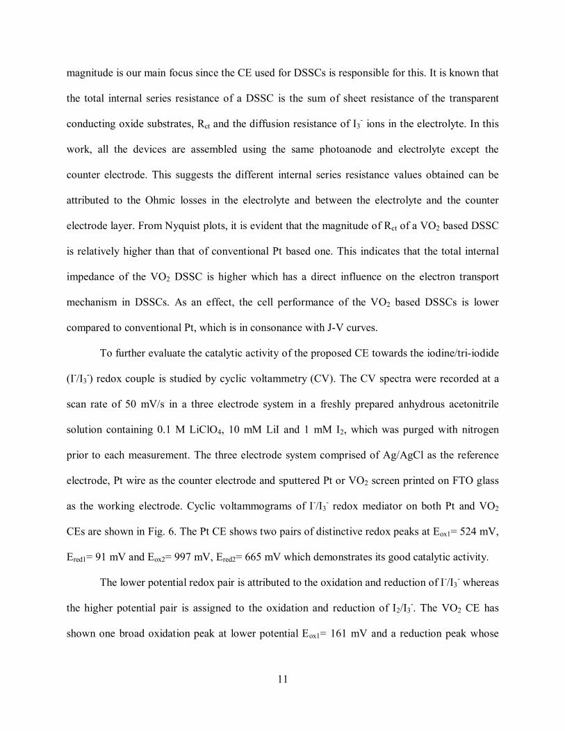
3.3. Electrochemical characterization
In order to better understand the electrocatalytic performance of proposed CE towards the
reduction of l3-, electrochemical impedance spectroscopy (EIS) measurements were conducted
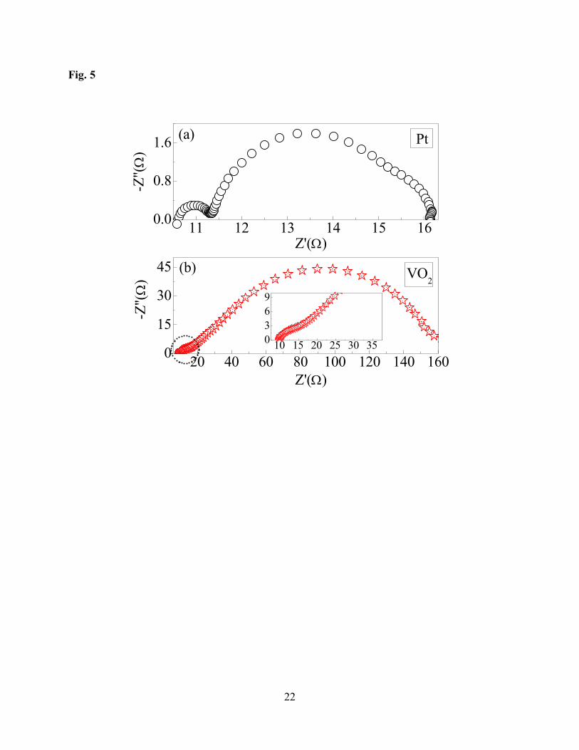
on full cells fabricated with CEs of VO2 and for reference Pt CEs was used. The impedance
spectra were collected under dark conditions at a bias of 0.8 V in the frequency range 0.1 Hz to 1
MHz. The obtained Nyquist plots of Pt and VO2 full cells are displayed in Fig. 5a and Fig. 5b,
respectively. The EIS spectra exhibited two semicircles, which describe the different impedance
contributions of DSSC. In case of Pt the semicircles are well defined whereas in VO2 (M1), the
semicircles are convoluted. In inset figure the encircled portion of Fig. 5b data is plotted in close
up for better visibility. The first semicircle in the high frequency region (on the extreme left)
describes the charge transfer resistance at the CE/electrolyte interface (Rct). The Rct is
determined by the diameter of the high frequency semi-circle in the Nyquist plots and its
11
magnitude is our main focus since the CE used for DSSCs is responsible for this. It is known that
the total internal series resistance of a DSSC is the sum of sheet resistance of the transparent
conducting oxide substrates, Rct and the diffusion resistance of I3- ions in the electrolyte. In this
work, all the devices are assembled using the same photoanode and electrolyte except the
counter electrode. This suggests the different internal series resistance values obtained can be
attributed to the Ohmic losses in the electrolyte and between the electrolyte and the counter
electrode layer. From Nyquist plots, it is evident that the magnitude of Rct of a VO2 based DSSC
is relatively higher than that of conventional Pt based one. This indicates that the total internal
impedance of the VO2 DSSC is higher which has a direct influence on the electron transport
mechanism in DSSCs. As an effect, the cell performance of the VO2 based DSSCs is lower
compared to conventional Pt, which is in consonance with J-V curves.
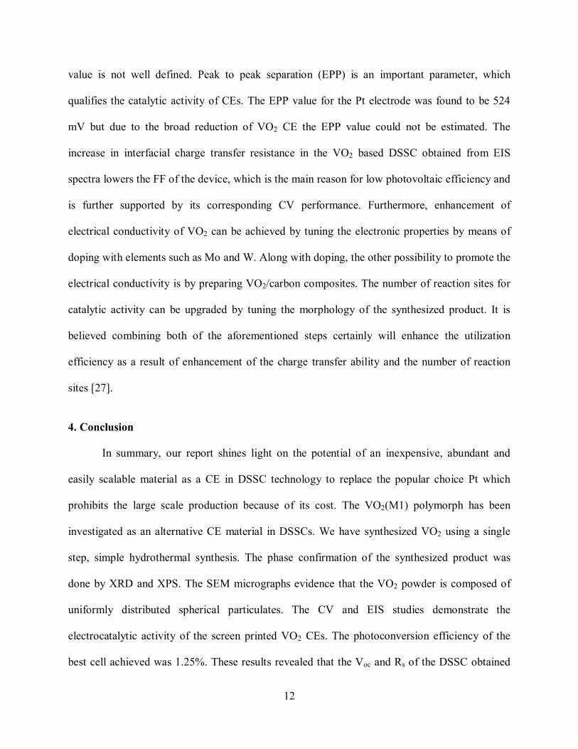
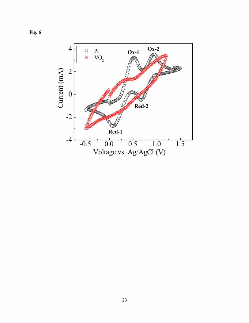
To further evaluate the catalytic activity of the proposed CE towards the iodine/tri-iodide
(I-/I3-) redox couple is studied by cyclic voltammetry (CV). The CV spectra were recorded at a
scan rate of 50 mV/s in a three electrode system in a freshly prepared anhydrous acetonitrile
solution containing 0.1 M LiClO4, 10 mM LiI and 1 mM I2, which was purged with nitrogen
prior to each measurement. The three electrode system comprised of Ag/AgCl as the reference
electrode, Pt wire as the counter electrode and sputtered Pt or VO2 screen printed on FTO glass
as the working electrode. Cyclic voltammograms of I-/I3- redox mediator on both Pt and VO2
CEs are shown in Fig. 6. The Pt CE shows two pairs of distinctive redox peaks at Eox1= 524 mV,
Ered1= 91 mV and Eox2= 997 mV, Ered2= 665 mV which demonstrates its good catalytic activity.
The lower potential redox pair is attributed to the oxidation and reduction of I-/I3- whereas
the higher potential pair is assigned to the oxidation and reduction of I2/I3-. The VO2 CE has
shown one broad oxidation peak at lower potential Eox1= 161 mV and a reduction peak whose
12
value is not well defined. Peak to peak separation (EPP) is an important parameter, which
qualifies the catalytic activity of CEs. The EPP value for the Pt electrode was found to be 524
mV but due to the broad reduction of VO2 CE the EPP value could not be estimated. The
increase in interfacial charge transfer resistance in the VO2 based DSSC obtained from EIS
spectra lowers the FF of the device, which is the main reason for low photovoltaic efficiency and
is further supported by its corresponding CV performance. Furthermore, enhancement of
electrical conductivity of VO2 can be achieved by tuning the electronic properties by means of
doping with elements such as Mo and W. Along with doping, the other possibility to promote the
electrical conductivity is by preparing VO2/carbon composites. The number of reaction sites for
catalytic activity can be upgraded by tuning the morphology of the synthesized product. It is
believed combining both of the aforementioned steps certainly will enhance the utilization
efficiency as a result of enhancement of the charge transfer ability and the number of reaction
sites [27].
4. Conclusion
In summary, our report shines light on the potential of an inexpensive, abundant and
easily scalable material as a CE in DSSC technology to replace the popular choice Pt which
prohibits the large scale production because of its cost. The VO2(M1) polymorph has been
investigated as an alternative CE material in DSSCs. We have synthesized VO2 using a single
step, simple hydrothermal synthesis. The phase confirmation of the synthesized product was
done by XRD and XPS. The SEM micrographs evidence that the VO2 powder is composed of
uniformly distributed spherical particulates. The CV and EIS studies demonstrate the
electrocatalytic activity of the screen printed VO2 CEs. The photoconversion efficiency of the
best cell achieved was 1.25%. These results revealed that the Voc and Rs of the DSSC obtained
13
using VO2 as the CE are significant in the first attempt of study though inferior to that of the
DSSCs made of Pt CEs. Our future investigations will be focused on enhancing the efficiency,
the stability and the long term operation of DSSCs made with VO2 CEs. Though the obtained
efficiencies are still below that of Pt, these primary results are encouraging and provide a scope
to the search for abundant and low cost, environmentally friendly materials as an effective
alternate for DSSCs.
Acknowledgements
Dr. J. Buckman of Institute of Petroleum Engineering, Heriot-Watt University (HWU) is
gratefully acknowledged for the access to SEM facilities and G.R.M thanks A. Boccolini of
HWU for some scientific discussions. Part of this work was supported by the Council of
Scientific and Industrial Research, Govt. Of India, sponsored projects (CSC0132 and CSC0122),
Board of Research in Nuclear Sciences and EPSRC Supersolar Hub.
14
References
[1] M. A. Hasan, and K. Sumathy, Renewable and Sustainable Energy Reviews 14 (7), 1845
(2010).
[2] B. O'regan, and M. Grätzel, Nature 353 (6346), 737 (1991).
[3] M. Grätzel, Prog. Photovoltaics: Res. Appl. 14 (5), 429 (2006).
[4] M. Wu, and T. Ma, ChemSusChem 5 (8), 1343 (2012).
[5] M. Wu, and T. Ma, J. Phys. Chem. C 118 (30), 16727 (2014).
[6] S. Yun, A. Hagfeldt, and T. Ma, Adv. Mater. 26 (36), 6210 (2014).
[7] M. Ye, X. Wen, M. Wang, J. Iocozzia, N. Zhang, C. Lin, and Z. Lin, Materials Today 18
(3), 155 (2015).
[8] S. Yun, Y. Liu, T. Zhang, and S. Ahmad, Nanoscale 7 (28), 11877 (2015).
[9] J. Theerthagiri, A. R. Senthil, J. Madhavan, and T. Maiyalagan, ChemElectroChem 2 (7),
928 (2015).
[10] M. Wu, X. Lin, Y. Wang, L. Wang, W. Guo, D. Qi, X. Peng, A. Hagfeldt, M. Grätzel, and T.
Ma, J. Am. Chem. Soc. 134 (7), 3419 (2012).
[11] M. Wu, X. Lin, A. Hagfeldt, and T. Ma, Chem. Commun. 47 (15), 4535 (2011).
[12] J. WeiáGuo, and H. GuiáYang, Chem. Commun. 49 (53), 5945 (2013).
[13] J. Xia, C. Yuan, and S. Yanagida, ACS Appl. Mater. Interfaces 2 (7), 2136 (2010).
[14] D. Paul Joseph, M. Saravanan, B. Muthuraaman, P. Renugambal, S. Sambasivam, S. Philip
Raja, P. Muthuraaman, and C. Venkateswaran, Nanotechnology 19, 485707 (2008).
[15] G. R. Mutta, S. R. Popuri, M. Maciejczyk, N. Robertson, M. Vasundhara, J. Wilson and N.
Bennett, Materials Research Express 3, 035501 (2016).
[16] W. Cheng, G. Zeng, and M. Niederberger, J. Mater. Chem. A 3 (6), 2861 (2015).
[17] M. Yu, Y. Zeng, Y. Han, X. Cheng, W. Zhao, C. Liang, Y. Tong, H. Tang, and X. Lu, Adv.
15
Funct. Mater. 25, 3534 (2015).
[18] S. R. Popuri, A. Artemenko, C. Labrugere, M. Miclau, A. Villesuzanne, and M. Pollet, J.
Solid State Chem. 213, 79 (2014).
[19] S. R. Popuri, M. Miclau, A. Artemenko, C. Labrugere, A. Villesuzanne, and M. Pollet,
Inorganic Chemistry 52 (9), 4780 (2013).
[20] J. Zhou, Y. Gao, Z. Zhang, H. Luo, C. Cao, Z. Chen, L. Dai, and X. Liu, Scientific Reports
3, 3029 (2013).
[21] P. Markov, R. E. Marvel, H. J. Conley, K. J. Miller, R. F. Haglund Jr, and S. M. Weiss,
ACS Photonics 2 (8), 1175 (2015).
[22] J. Rodríguez-Carvajal, Physica B: Condensed Matter 192 (1), 55 (1993).
[23] N. Alov, D. Kutsko, I. Spirovova, and Z. Bastl, Surface Science 600 (8), 1628 (2006).
[24] G. Silversmit, D. Depla, H. Poelman, G. B. Marin, and R. De Gryse, J. Electron
Spectroscopy and Related Phenomena 135 (2), 167 (2004).
[25] J. Mendialdua, R. Casanova, and Y. Barbaux, J. Electron Spectroscopy and Related
Phenomena 71 (3), 249 (1995).
[26] Z. L. Ku, X. Li, G. H. Liu, H. Wang, Y. G. Rong, M. Xu, L. F. Liu, H. Hu, Y. Yang, H. W.
Han, J. Mater. Chem. A 1, 237 (2013).
[27] M. Shahpari, A. Behjat, M. Khajaminian, and N. Torabi, Solar Energy 119, 45 (2015).
16
Table 1. Photovoltaic parameters of DSSCs using VO2 and Pt CEs.
Counter Electrode Voc (V) Jsc
(mAcm-2) FF (%) η (%) Rs (Ωcm-2)
Rsh (KΩcm-2)
VO2 0.61 4.67 43.72 1.25 27 2.84
Pt 0.64 14.90 73.74 7.08 5 2.85
17
Figure captions page
Fig. 1. Schematic representation of the assembled liquid based DSSC. It is comprised of
transparent conducting oxide (FTO) on glass, a nanoparticle photoelectrode (such as TiO2)
sensitized with N719 dye, hole-conducting iodine based liquid electrolyte and platinum or VO2
deposited on FTO coated glass back contact.
Fig. 2. Powder XRD patterns of VO2 powder and screen printed VO2 CE; star symbol represents
the Bragg reflections from the FTO coated glass substrate; bottom green markers highlight the
Bragg reflection positions associated with VO2(M1) (JCPDS card number 01-82-0661) (b) Core
level XPS spectra of V 2p3/2 and O 1s. Inset shows the high resolution valence band region of
VO2(M1) XPS spectra.
Fig. 3. SEM images of VO2 powder: (a) at low magnification, (b) at higher magnification; screen
printed VO2 thin films: (c) at low magnification, (d) at higher magnification.
Fig. 4. The J-V curves of the DSSCs fabricated with VO2 and Pt counter electrodes, respectively.
Fig. 5. Nyquist plots of full cells assembled with VO2 and Pt counter electrodes, respectively.
Fig. 6. Cyclic voltammograms of VO2 and Pt counter electrodes measured at a fixed scan rate of
50 mVs-1 using three electrode configurations.
18
Fig. 1
I3-I-
FTO coating
ElectrolyteDye sensitizer
Pt/ VO2
TiO2 nanocrystalline
Glass
19
Fig. 2
30 40 50 60 70
0
2000
560056105620563056405650
(-31
3)
***
Powder Film Bragg reflections
*
* FTO glass
(-21
2)
(130
)(-3
21)
(-41
1)(-
231)
(022
)(-22
2)(-
331)
(-22
1)(-3
02)
(012
)
(002
)
(-21
1)
(-10
2)
(011
)
(110
)
0 3 6 9 120
20406080
514 516 518 528 532 536 5400
4000
8000
12000
16000
V 3d
O 2p O 1s Data Fitting
V 2p3/2
(V4+)
V 2p3/2
(V5+) V O1s C O1s
V 2p3/2
(b)
(a)
Two theta (degree)
Binding energy (eV)
Inte
nsity
(a.u
.)In
tens
ity (a
.u.)

20
Fig. 3
10 µm10 µm
20 µm
20 µm 10 µm
(a)
(c) (d)
(b)
10 µm
21
Fig. 4
0.0 0.1 0.2 0.3 0.4 0.5 0.60
3
6
9
12
15
C
urre
nt d
ensi
ty (m
Acm
-2)
Pt VO
2
Voltage (V)
22
Fig. 5
10 15 20 25 30 350369
11 12 13 14 15 160.0
0.8
1.6
(b)
(a)
20 40 60 80 100 120 140 1600
15
30
45
Z'()
VO2
-Z''(
) Pt
Z'()
-Z''(
)
23
Fig. 6
-0.5 0.0 0.5 1.0 1.5-4
-2
0
2
4
Red-2
Red-1
Ox-1 Ox-2
C
urre
nt (m
A)
Voltage vs. Ag/AgCl (V)
Pt VO2