dwg 002 blueprint reading geometric terminology orthographic...
TRANSCRIPT
Copyright © 2012 Boeing. All rights reserved.
DWG 002
Blueprint Reading
Geometric Terminology Orthographic Projection
Instructor Guide

Copyright © 2012 Boeing. All rights reserved.
Introduction
Module Purpose The purpose of the Blueprint Reading modules is to introduce students to production drawings and blueprint reading. Module Objectives By the end of all Blueprint Reading modules, students should be able to:
• Describe the Picture Sheet and locate information contained in the three major Picture Sheet areas.
• Locate the Title Block on a drawing and identify the name, purpose of a drawing, and other fields depicted.
• Use the Drawing Numbering System, prefixes, and part numbers.
• Identify and explain the purpose of the un-dimensioned picture sheet as a template.
• Use orthographic projection to complete the third view when given two views.
• Demonstrate conventional line standards and identify callouts, including conventional symbols and fastener symbols.
• Identify the types of views, including Standard views, Detail views, Sectional views, Auxiliary views, and be able to demonstrate the use of cut views and directional arrows.
• Identify types of dimensioning, including Linear, Angular, Arc, Circle and Cylinder, Coordinate, and be able to explain the purpose of tolerancing.
Topics Covered In this module topics covered include:
Geometric Terminology • Circles • Degrees • Arcs
Orthographic Projection • Purpose of orthographic projections • Airplane views and reference planes

Copyright © 2012 Boeing. All rights reserved.
Geometric Terminology
Introduction In blueprint reading, some words and phrases convey different meanings when used in everyday conversation. It is essential to know the meaning of such words and phrases. Study the following explanations and make certain you understand them before attempting to proceed further in the text. It is not necessary to memorize these definitions word for word, but it is essential to understand them. The objectives of this section are to:
• Identify the basic lines and geometric shapes used in production drawings.
• Describe basic geometry definitions and terminology used in drawings.
Lines Drawings consist of straight and curved lines – some lines solid and others broken. Broken lines usually have particular meanings such as hidden lines, centerlines, and phantom lines. The uses of these lines are addressed later. Solid lines show edges of an object, provide dimensioning information, or indicate labels and callouts. Circles A circle is an example of a curved line in which all points on the line are the same distance from a center point. The distance around a circle is called its circumference.
Circle
Copyright © 2012 Boeing. All rights reserved.
Geometric Terminology (continued)
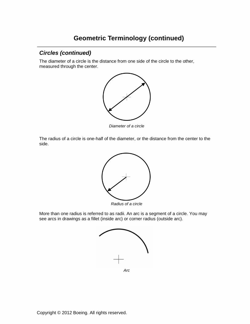
Circles (continued) The diameter of a circle is the distance from one side of the circle to the other, measured through the center.
Diameter of a circle
The radius of a circle is one-half of the diameter, or the distance from the center to the side.
Radius of a circle
More than one radius is referred to as radii. An arc is a segment of a circle. You may see arcs in drawings as a fillet (inside arc) or corner radius (outside arc).
Arc

Copyright © 2012 Boeing. All rights reserved.
Geometric Terminology (continued)
Circles (continued) You’ll see curved and straight lines that touch other curved lines or circles. When these lines simply touch at a single point, even if they are extended, they are referred to as tangent lines. On the other hand, if they cross other lines, whether straight or curved, they are called intersecting lines.
Tangent Lines
In the diagram above, line AB is tangent to the arc. In the example below, line CD is intersecting the arc at two points.
Intersecting the arc
A
B
D
C
Copyright © 2012 Boeing. All rights reserved.
Geometric Terminology (continued)
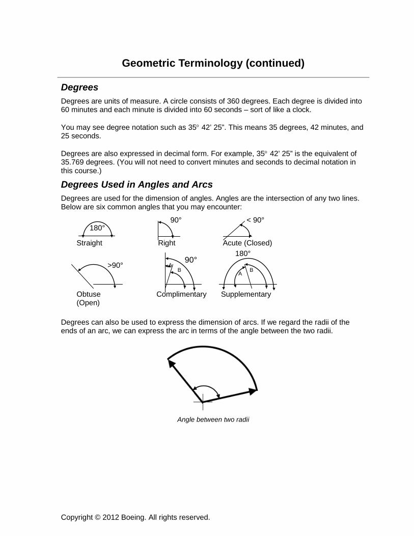
Degrees Degrees are units of measure. A circle consists of 360 degrees. Each degree is divided into 60 minutes and each minute is divided into 60 seconds – sort of like a clock. You may see degree notation such as 35° 42’ 25”. This means 35 degrees, 42 minutes, and 25 seconds. Degrees are also expressed in decimal form. For example, 35° 42’ 25” is the equivalent of 35.769 degrees. (You will not need to convert minutes and seconds to decimal notation in this course.)
Degrees Used in Angles and Arcs Degrees are used for the dimension of angles. Angles are the intersection of any two lines. Below are six common angles that you may encounter: Degrees can also be used to express the dimension of arcs. If we regard the radii of the ends of an arc, we can express the arc in terms of the angle between the two radii.
Angle between two radii
Straight Right Acute (Closed)
Obtuse Complimentary Supplementary (Open)
180° 90° < 90°
>90° A B
90° 180°
A B
Copyright © 2012 Boeing. All rights reserved.
Geometric Terminology (continued)
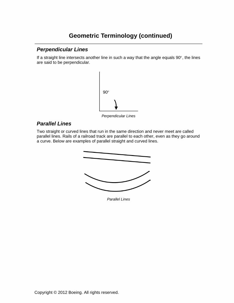
Perpendicular Lines If a straight line intersects another line in such a way that the angle equals 90°, the lines are said to be perpendicular.
Perpendicular Lines
Parallel Lines Two straight or curved lines that run in the same direction and never meet are called parallel lines. Rails of a railroad track are parallel to each other, even as they go around a curve. Below are examples of parallel straight and curved lines.
Parallel Lines
90°

Copyright © 2012 Boeing. All rights reserved.
Geometric Terminology (continued)
Practice Review
Practice Review 1. A circle:
A. Is a curved line B. Has all points equal distance from the circle’s center C. Can be depicted as a solid or broken line D. All of the above
2. The circumference of a circle is the:
A. Distance between any two points on a circle B. Distance of any two points through the center of the circle C. Distance around a circle D. All of the above
3. The diameter of a circle is the distance:
A. Between any two points on a circle B. From one side of a circle to the other side through the center of the circle C. Distance around a circle D. None of the above
4. The radius of a circle is:
A. The distance from the center of a circle to its side B. Half the diameter of a circle C. The distance around a circle D. Both a and b
5. An arc:
A. Is a segment of a circle B. Can be measured in degrees C. May be tangent to lines D. Is all of the above
Copyright © 2012 Boeing. All rights reserved.
Geometric Terminology
Practice Review (continued)
Practice Review (continued) 6. A fillet or a corner radius shown in a drawing may be an example of what?
A. Intersecting lines B. Two perpendicular lines C. An arc D. A circle
7. Two lines are said to be perpendicular if what is true?
A. The lines intersect forming a 90° angle B. The lines are parallel C. The lines form a right angle D. Both a and c
8. Parts of a degree may be expressed as:
A. Decimals B. Minutes C. Seconds D. All of the above
Copyright © 2012 Boeing. All rights reserved.
Geometric Terminology (continued)
Summary In this section, you were introduced to some common geometric terminology that you encounter as you read blueprints. After completing this section, you should be familiar with the following terms:
• Curved and Straight Lines
• Circles
• Diameter
• Radius
• Arc
• Tangent
• Intersecting Lines
• Angles
• Degrees (in decimals, minutes, and seconds)
• Perpendicular
• Parallel
Copyright © 2012 Boeing. All rights reserved.
Orthographic Projection
Introduction The drawing found in the picture area is the basis of the communication process between engineering and manufacturing. Picture sheets usually contain orthographic projections of a part, assembly, or installation, rather than a pictorial view. An orthographic view allows the engineer to completely describe a three-dimensional object on a flat (two-dimensional) piece of paper – the blueprint. The objectives for this section are to:
• Explain why orthogonal projection is used in engineering drawings.
• Use Orthographic projection to be able to complete the third view when given two views.
Technique Orthographic projection is a technique used to show a three-dimensional object on a flat two-dimensional surface. Objects are drawn as if they were in a glass box, with the image of the part on the surfaces of the box. The drafter draws each view as though the box has hinges and sides hinged out. Orthographic projection is the most common method used to produce views on picture sheets. This technique can produce up to six views. The six basic views are as follows:
• Left-side view
• Plan view (Rear view)
• Top view
• Front view
• Right-side view
• Bottom view

Copyright © 2012 Boeing. All rights reserved.
Orthographic Projection (continued)
Technique (continued)
Orthographic projection
Copyright © 2012 Boeing. All rights reserved.
Orthographic Projection (continued)
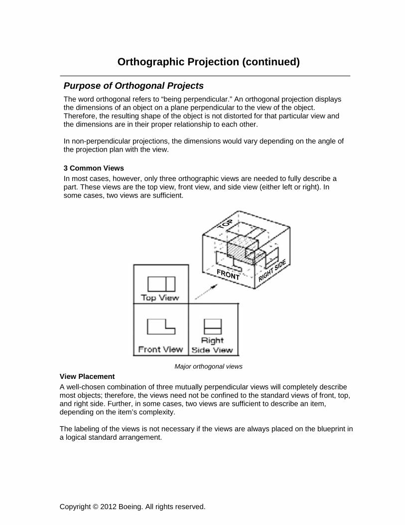
Purpose of Orthogonal Projects The word orthogonal refers to “being perpendicular.” An orthogonal projection displays the dimensions of an object on a plane perpendicular to the view of the object. Therefore, the resulting shape of the object is not distorted for that particular view and the dimensions are in their proper relationship to each other. In non-perpendicular projections, the dimensions would vary depending on the angle of the projection plan with the view. 3 Common Views In most cases, however, only three orthographic views are needed to fully describe a part. These views are the top view, front view, and side view (either left or right). In some cases, two views are sufficient.
Major orthogonal views
View Placement A well-chosen combination of three mutually perpendicular views will completely describe most objects; therefore, the views need not be confined to the standard views of front, top, and right side. Further, in some cases, two views are sufficient to describe an item, depending on the item’s complexity. The labeling of the views is not necessary if the views are always placed on the blueprint in a logical standard arrangement.

Copyright © 2012 Boeing. All rights reserved.
Orthographic Projection (continued)
View Placement (continued) The standard practice for the standard view arrangement is to place the top view directly above the front view, and place the right side view to the right of the front view. Not only is this a logical and natural placement of the views, but it also allows the number of dimensions that are common to the two adjacent views to be simplified. That is, a dimension on one view need not be depicted on an adjacent view. Hidden Lines In many complicated drawings, all edges and surfaces of the item cannot be represented in one view. To aid the reader, drawings contain hidden lines to depict hidden edges that are concealed from view. Hidden edges may take forms such as straight lines, regular geometric shapes, or irregular shapes. Notice the views below:
Examples of hidden lines
A.
B.

Copyright © 2012 Boeing. All rights reserved.
Orthographic Projection (continued)
Practice Review
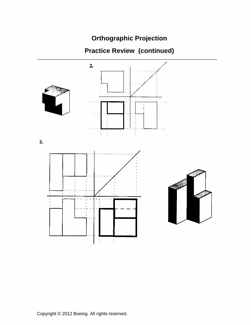
Practice Review In this practice review, you’ll be given several orthographic views. You will complete the missing view by transferring the lines from the provided views. An example is provided below on the Picture Sheets. To transfer the lines from one view to the other, continue the line from one to the next view using a straight edge. Follow the same procedure as shown below. Look at the shaded illustration to see what the object looks like. Ask your instructor for help if you need assistance.
1.
Copyright © 2012 Boeing. All rights reserved.
Orthographic Projection
Practice Review (continued)
3.

Copyright © 2012 Boeing. All rights reserved.
Orthographic Projection
Practice Review (continued)
Copyright © 2012 Boeing. All rights reserved.
Orthographic Projection (continued)
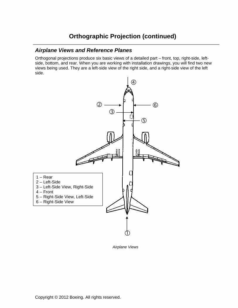
Airplane Views and Reference Planes Orthogonal projections produce six basic views of a detailed part – front, top, right-side, left-side, bottom, and rear. When you are working with installation drawings, you will find two new views being used. They are a left-side view of the right side, and a right-side view of the left side.
Airplane Views
1 – Rear 2 – Left-Side 3 – Left-Side View, Right-Side 4 – Front 5 – Right-Side View, Left-Side 6 – Right-Side View
Copyright © 2012 Boeing. All rights reserved.
Orthographic Projection (continued)
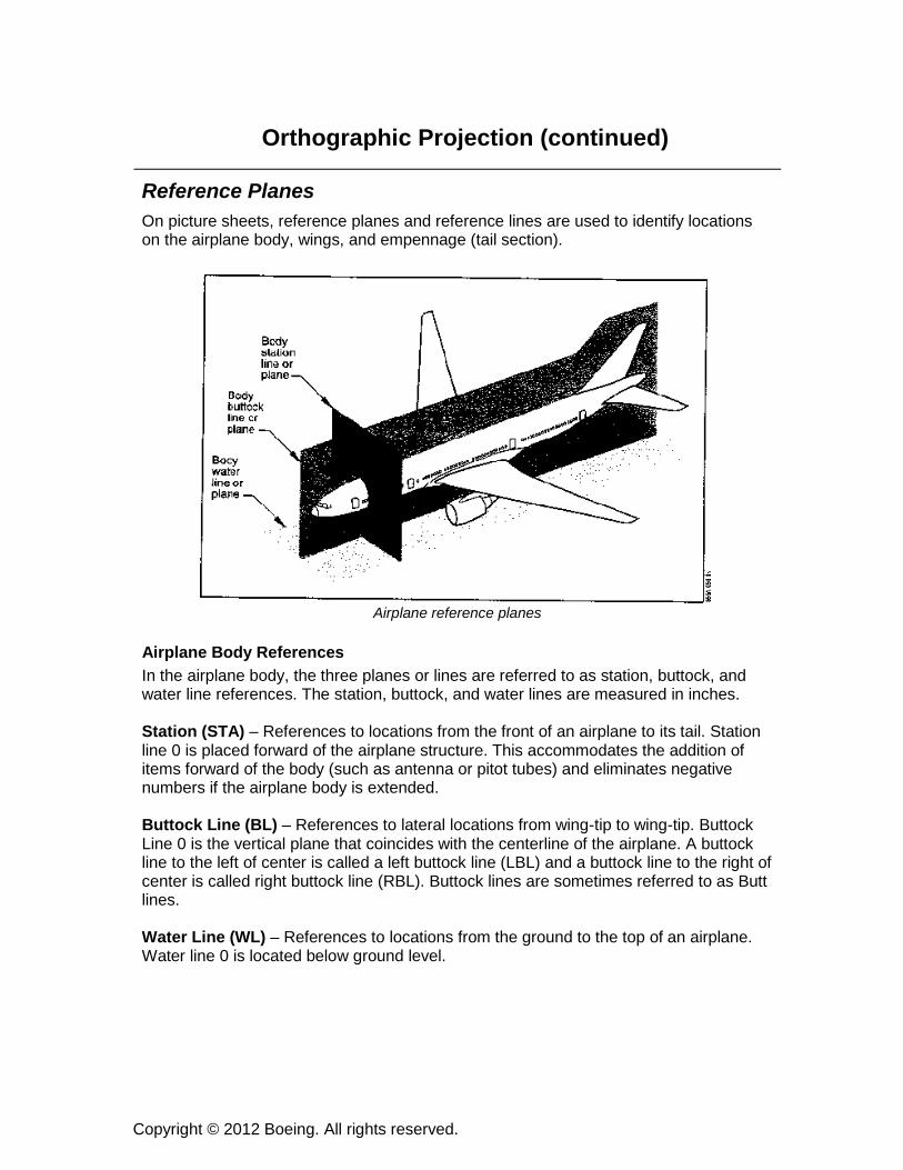
Reference Planes On picture sheets, reference planes and reference lines are used to identify locations on the airplane body, wings, and empennage (tail section).
Airplane reference planes
Airplane Body References In the airplane body, the three planes or lines are referred to as station, buttock, and water line references. The station, buttock, and water lines are measured in inches. Station (STA) – References to locations from the front of an airplane to its tail. Station line 0 is placed forward of the airplane structure. This accommodates the addition of items forward of the body (such as antenna or pitot tubes) and eliminates negative numbers if the airplane body is extended. Buttock Line (BL) – References to lateral locations from wing-tip to wing-tip. Buttock Line 0 is the vertical plane that coincides with the centerline of the airplane. A buttock line to the left of center is called a left buttock line (LBL) and a buttock line to the right of center is called right buttock line (RBL). Buttock lines are sometimes referred to as Butt lines. Water Line (WL) – References to locations from the ground to the top of an airplane. Water line 0 is located below ground level.
Copyright © 2012 Boeing. All rights reserved.
Orthographic Projection (continued)
Airplane Body References (continued)
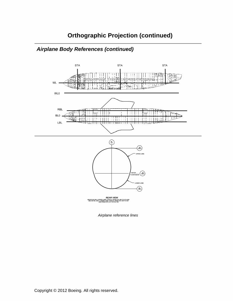
Airplane reference lines
WL148.5
REAR VIEWABOVE WL208.1 UPPER LOBE TYPICAL FROM STA 480 TO STA 808
BELOW WL 208.1 LOWER LOBE TYPICAL FROM STA 390 TO 540AND FROM STA 727 TO STA 730
WL208.1
TOP OFFLOOR BEAM
WL306.5
BL0.0
UPPER LOBE
LOWER LOBE
Copyright © 2012 Boeing. All rights reserved.
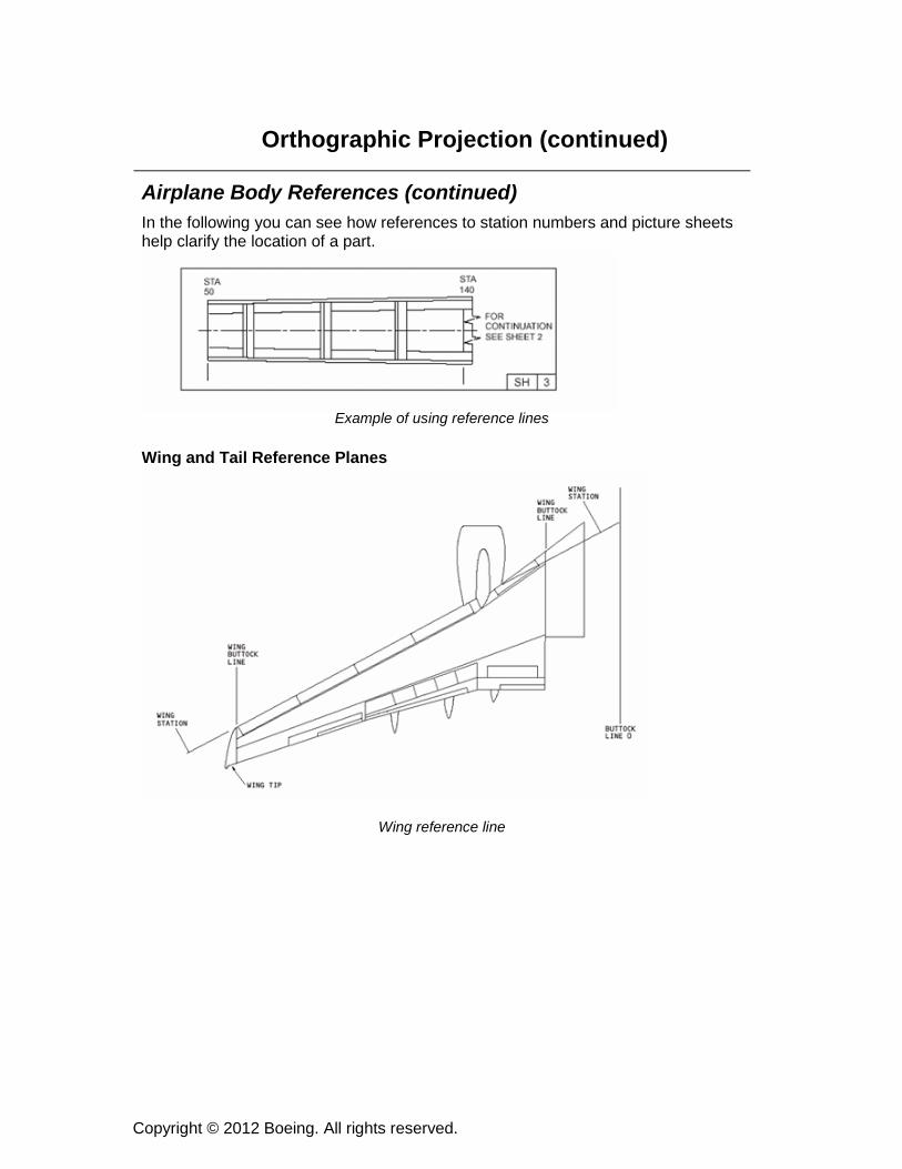
Orthographic Projection (continued)
Airplane Body References (continued) In the following you can see how references to station numbers and picture sheets help clarify the location of a part.
Example of using reference lines
Wing and Tail Reference Planes
Wing reference line
Copyright © 2012 Boeing. All rights reserved.
Orthographic Projection (continued)
Practice Review
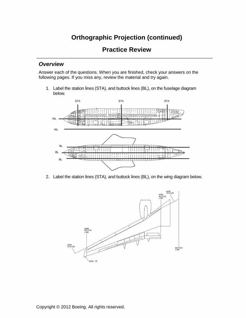
Overview Answer each of the questions. When you are finished, check your answers on the following pages. If you miss any, review the material and try again.
1. Label the station lines (STA), and buttock lines (BL), on the fuselage diagram below.
2. Label the station lines (STA), and buttock lines (BL), on the wing diagram below.

Copyright © 2012 Boeing. All rights reserved.
Orthographic Projection (continued)
Student Activity
Student Activity Ask students to follow these instructions: Divide the class into pairs. Give each pair a random object. Ask each student to draw the figure below on a separate sheet of paper that is larger than this view. Assign each student a view to draw. Ask one person in each pair to draw the isometric view of their object. Tell students to share their drawing with their partner. Ask students to gather around instructor’s table and ask them to match objects with views.
Left Side View
Top View
Front View
Bottom View
Right Side View
Rear View
Copyright © 2012 Boeing. All rights reserved.
Orthographic Projection (continued)
Summary This section introduced students to Orthogonal Projection. There are six possible principal views. They are the top, front, right-side, bottom, rear, and left-side. Students will encounter two additional views – a left-side view of the right side and a right-side view of the left side. A combination of three mutually perpendicular views will completely describe most objects; therefore, the views need not be confined to the standard views of front, top and right-side. Sometimes the part can be described in just two views. The standard practice for the standard view arrangement is to place the top view directly above the front view, and place the right-side view to the right of the front view. The labeling of the views is not necessary if the views are always placed on the blueprint in a logical standard arrangement. Many views conceal edges of the item. Hidden lines are dashed-lines depicted on orthogonal views to illustrate hidden edges. Picture sheets will frequently refer to reference planes and lines that describe the location of assemblies and installations on an airplane. These references are called station, buttock, and water lines (or planes). Before proceeding, students should be able to interpret orthogonal projections with confidence. Students should also be able to describe the airplane reference planes. Ask students if they need clarification on any points in this section.