precision measuring toolssnocamp.s3.amazonaws.com/snocamp/uploads/files/p… · ·...
TRANSCRIPT

Precision Measuring Tools
Participant Self-Paced Workbook
Introduction Course Purpose
The purpose of this course is to introduce you to precision measuring tools. In this course you will learn about decimals and tolerances as well as how to use the following tools:
• Twelve-Inch Scale • Six-Inch Dial Caliper • Outside Micrometer (0-1) inch • Ball Gauges
Once you complete a topic, a skill check is available for you to demonstrate what you have read and practiced. Check your answers with those that are provided to see how well you understood the material.
Topics • Determining Decimals and Tolerances Covered • Using a Twelve-Inch Scale
• Using a Six-Inch Dial Caliper • Measuring with an Outside Micrometer (0-1) inch • Using Ball Gauges with a Micrometer
Course At the end of this course, you will be able to: Objectives
Add and subtract decimals and determine the tolerance range of given dimensions.
Use the following pieces of equipment to measure objects:
• Twelve-Inch Scale • Six-Inch Dial Caliper • Outside Micrometer (0-1) inch • Ball Gauges

Objectives Measurement
Your understanding of the section objectives will be measured by your participation in the following activities:
• Demonstrating how to add decimals and determine the tolerance of a given number.
• Converting fractions to decimal equivalents by using a Decimal Equivalents Card
• Using a scale to determine the correct length of several items.
• Using a Six-Inch dial caliper to determine the inside, outside, and depth measurements of various items.
• Using an outside micrometer to measure various items. • Using ball gauges and a micrometer to measure hole
sizes and check for hole size consistency.
Each section contains Skill Checks to assess your progress. A comprehensive Final Test is administered at the completion of the sections. You will be required to achieve a grade of 80% or better in order to pass the Final Test.
Class Length The time you need to complete the course depends on your schedule and level of effort If you were to complete the entire course in one session, you would need about 8 hours.

Materials To complete this course you will be given the following:
• A Student Guide • A calculator • Pencils • Magnifying glass • Decimal Equivalents Card • Twelve inch Scale • 0-1 inch outside Micrometer • Six-Inch Dial Caliper • Ball Gauges • Test kits containing items to measure • Final Test.
New Terminology
Tolerance – The degree of accuracy required for a dimension, expressed as ‘plus or minus’ (+/-) a specific amount.
Graduation – Marks on an instrument or tool that measure degree or quantity.
Nominal – The dimension or quantity called out on an Engineering drawing

I C O N D E F I N I T I O N S
This icon is used to introduce a new section or topic.
This icon indicates that you will need to read the materials.
This icon represents a handout or piece of equipment that you should get from your class Facilitator. This includes instruments as well as Skill Checks.
This icon indicates that there is some Skill Check that you can do to reinforce what you just read. It also represents the final Skill Check.

S E C T I O N 1 : U S I N G D E C I M A L S A N D T O L E R A N C E S
Introduction To perform fabrication work, you must understand decimal notation and tolerances. In this section, you will learn about the decimal system and practice performing math operations with decimals.
Objectives At the end of this section, you will be able to:
• Convert fractions to decimal equivalents • Add and subtract decimals. • Determine the tolerance range (upper and lower
boundaries) of given dimensions.
Resources • Calculator • Decimal Equivalents Card
Linear dimensions on all company drawings are expressed in decimal notation. This system allows engineers to clearly specify the degree of accuracy, or tolerance, that is required for any dimension. All linear measuring tools used at most companies read in decimals. It is therefore important that you be able to read and calculate decimals.
In decimal notation, inches are written to the left of a decimal point, while fractions of an inch are written to the right of a decimal point and are expressed in units of 10.
For example:
100. = One hundred inches
Decimal Values

10. = Ten inches 1. = One inch
.1 = One-tenth of an inch
.01 = One-hundredth of an inch
.001 = One-thousandth of an inch .0001 = One-ten thousandths of an inch
Decimal Values Figure 2-1 shows the value of different positions on either side of the decimal point for the number 1.1111.
Whole Numbers
D e c i m a l s
1 • 1 1 1 1
Whole N
umbers
Decim
al Point
Tenths
Hundredths
Thousandths
Ten T
housandths
Figure 2-1: Value of positions on either side of the decimal point.

The first number to the right of the decimal point is in tenths of an inch. There are 10 tenths in one inch. (.1000 x 10 = 1 inch). On the shop floor it is pronounced as one tenth of an inch.
The second number to the right of the decimal is in hundredths of an inch. There are 100 hundredths in one inch (.0100 x 100 = 1). The number .010 is pronounced one hundredth of an inch.
The third number after the decimal is in thousandths of an inch and there are 1000 of them in one inch (.0010 x 1000 = 1 inch). The number .001 is pronounced one thousandth of an inch.
When dimensions are carried out to four decimal places, it is called ten thousandths of an inch. There are 10,000 of these in each inch. (.0001 x 10,000 = 1 inch).
Review The common shop way to read numbers is shown for each of the numbers below.
• 2.8576 Two and Eight Hundred Fifty-Seven Thousandths and Six-Tenths inches
• 4.050 inch Four and Fifty-Thousandths inches
• .0687 inch Sixty-Eight Thousandths and Seven-Tenths inch
• .500 inch Five-Hundred Thousandths inch
• .0067 inch Six-Thousandths and Seven-Tenths inch
Pronunciation questions will NOT be included on the Final Test.

______________________________________________
______________________________________________
______________________________________________
______________________________________________
______________________________________________
______________________________________________
______________________________________________
______________________________________________
______________________________________________
______________________________________________
Skill Check 1 Write out how you would say each number in shop language on the line provided. When you are done, check your answers against the answers on the following page.
1. .451
2. .897
3. 5.155
4. 7.1544
5. 3.2563
Skill Check 1 Check your answers from the previous page. Answers
1. Four hundred fifty-one thousandths 2. Eight hundred ninety-seven thousandths
3. Five and one hundred fifty-five thousandths
4. Seven and one-hundred fifty-four thousandths and four-tenths
5. Three and two-hundred fifty-six thousandths and three-tenths

Converting Fractions to Decimal Equivalents
In most cases, a measurement requirement will be given to you in a decimal format. By using the Decimal Equivalents Card you can easily convert a fraction to a decimal.
Simply find the fraction on the left side of the card and read its decimal equivalent on the right side of the card. For example, ¼” is the same as .250”.
Converting Fractions to Decimals
Exercise #1 You are asked to get a 5/16 drill bit. Because drill bits are usually measured in decimal sizes, you look at your drill card and notice that 5/16” corresponds with .3125 inches. When you go to the tool issue area, you ask for a .3125 drill bit rather than a 5/16.
Using your Decimal Equivalents Card, practice doing a few conversions in the exercise below. The answers are provided to assist you in making these conversions and understanding how to use the card.
Fraction Decimal Equivalent
3/8 __.3750______________
13/16 __.8125______________
1/8 __.1250______________
If you need help to complete this exercise, ask your facilitator for assistance. Continue practicing until you are comfortable with the conversion process.
Convert the fractions listed below to decimal equivalents. Skill Check Check your answers on the next page.
1
1. 7/16 is equivalent to ______________
2. 9/32 is equivalent to ______________
3. 3/8 is equivalent to ______________
4. 25/64 is equivalent to ______________
5. 15/16 is equivalent to ______________
6. 1/2 is equivalent to ______________
7. 3/32 is equivalent to ______________

Listed below are the answers to the Decimal Conversion Skill Check Skill Check from the previous page.
1 Answers
1. .4375
2. .2812
3. .3750
4. .3906
5. .2344
6. .5000
7. .0938
If you are comfortable with converting fractions to decimals with the Decimal Equivalent Card, move on to the next subject. If you are unsure of the conversion process, have your facilitator assist you.
________________________________________________
Adding and Subtracting Decimals
Adding Decimals
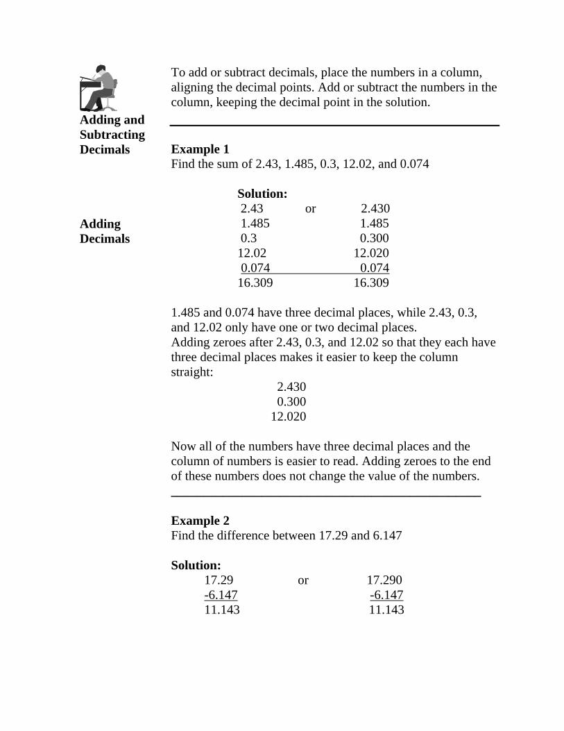
To add or subtract decimals, place the numbers in a column, aligning the decimal points. Add or subtract the numbers in the column, keeping the decimal point in the solution.
Example 1 Find the sum of 2.43, 1.485, 0.3, 12.02, and 0.074
Solution: 2.43 or 2.430 1.485 1.485 0.3 0.300 12.02 12.020 0.074 0.074
16.309 16.309
1.485 and 0.074 have three decimal places, while 2.43, 0.3, and 12.02 only have one or two decimal places. Adding zeroes after 2.43, 0.3, and 12.02 so that they each have three decimal places makes it easier to keep the column straight:
2.430 0.300
12.020
Now all of the numbers have three decimal places and the column of numbers is easier to read. Adding zeroes to the end of these numbers does not change the value of the numbers.
Example 2 Find the difference between 17.29 and 6.147
Solution: 17.29 or 17.290 -6.147 -6.147 11.143 11.143

______________ ______________
______________
______________
______________
______________
______________
______________
______________
______________
Skill Check 2 Add or subtract the following numbers and write your answers in the space provided. When you are finished, check your answers with the answer key on the next page.
Do NOT use a calculator for this part of the Skill Check. Be sure that the decimal point is correctly placed in each of your answers.
a) .2 + .07 + .5 =
b) 2.6 + 22.4 + .03 =
c) 22.8 + 5.009 + 613.2 =
d) .005 + 5 + 16.2 + .96 =
e) 28.74 – 16.32 =
f) 15.4 + 22 + .01 + 1.48 =
g) .005 – .0005 =
h) 1.431 – .562 =
i) 1.0020 – .2 =
j) 8.04 – 7.96 =

__________
__________
__________
__________
__________
You may use a calculator for the following problems.
k) 72.306 + 18.45 – 27.202 =
l) 14 – 6.3 + 2.739 =
m) 27.65 + 18.402 – 2.39 + 7.63 =
n) 18.0006 + 14.005 + 12.34 =
o) 93.8 – 16.4327 – 20.009 =

Skill Check 2 If you answered at least 12 of the 15 problems correctly, go onto the next section of this section. If you answered fewer than 12 problems correctly, review Adding And Subtracting Decimals (page 19), then do Skill Check 2 again. You may also ask the facilitator for assistance.
Answers
a) .2 + .07 + .5 = .77
b) 2.6 + 22.4 + .03 = 25.03
c) 22.8 + 5.009 +613.2 = 641.009
d) .005 + 5 + 16.2 + .96 = 22.165
e) 28.74 – 16.32 = 12.42
f) 15.4 + 22 + .01 +1.48 = 38.89
g) .005 - .0005 = .0045
h) 1.431 - .562 = .869
i) 1.0020 - .2 = .802
j) 8.04 - 7.96 = .08
k) 72.306 + 18.45 – 27.202 = 63.554
l) 14 – 6.3 + 2.739 = 10.439
m) 27.65 + 18.402 – 2.39 + 7.63 = 51.292
n) 18.0006 + 14.005 + 12.34 = 44.3456
o) 93.8 – 16.4327 – 20.009 = 57.3583
Dimensions & Tolerances
Now that you have learned how to add and subtract decimals, it’s time to apply your knowledge to Dimension Tolerances.
A dimension listed on a drawing is called a nominal dimension. Tolerances tell us how much discrepancy is allowed from the nominal dimension.
How much tolerance is allowed for a dimension is indicated by a plus (+) or minus (-) sign. The following are examples of tolerances, starting with ‘plus or minus four ten thousandths’.
• +/- .0004 • +/- .008 • +/- .01 • +/- .3

Drawing Tolerances
To determine the biggest dimension allowable, add the tolerance to the nominal dimension. To determine the smallest dimension allowable, subtract the tolerance from the nominal dimension.
Example:
A drawing requires a hole to be .39” from the edge. The tolerance is +/- .03”.
To find the biggest dimension allowable, add .03 to .39.
.39 + .03
.42
To find the smallest dimension allowable, subtract .03 from .39
.39 - .03
.36
For the nominal dimension of .39” in this drawing, the largest allowable dimension is .42”. The smallest allowable dimension is .36”.
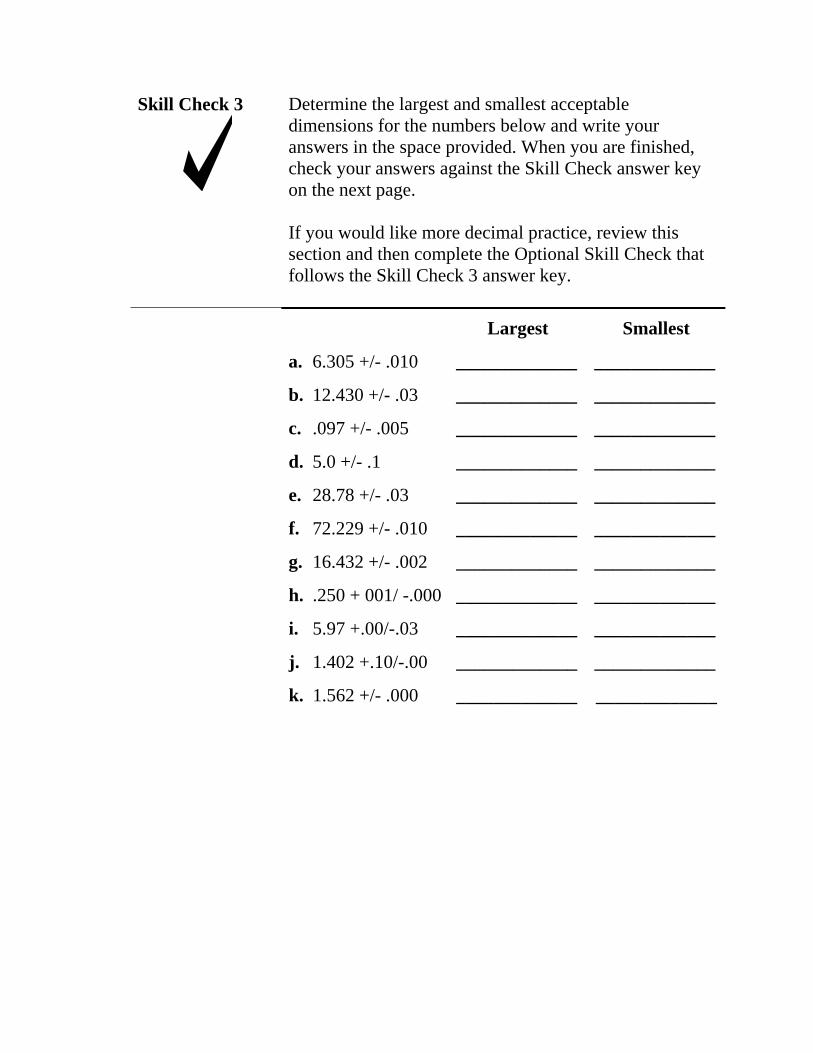
Skill Check 3 Determine the largest and smallest acceptable dimensions for the numbers below and write your answers in the space provided. When you are finished, check your answers against the Skill Check answer key on the next page.
If you would like more decimal practice, review this section and then complete the Optional Skill Check that follows the Skill Check 3 answer key.
Largest Smallest
a. 6.305 +/- .010 _____________ _____________
b. 12.430 +/- .03 _____________ _____________
c. .097 +/- .005 _____________ _____________
d. 5.0 +/- .1 _____________ _____________
e. 28.78 +/- .03 _____________ _____________
f. 72.229 +/- .010 _____________ _____________
g. 16.432 +/- .002 _____________ _____________
h. .250 + 001/ -.000 _____________ _____________
i. 5.97 +.00/-.03 _____________ _____________
j. 1.402 +.10/-.00 _____________ _____________
k. 1.562 +/- .000 _____________ _____________

Skill Check 3 Check your numbers with the answers below. Answers
Largest Smallest
a. 6.305 +/- .010 6.315 6.295
b. 12.430 +/- .03 12.460 12.400
c. .097 +/- .005 .102 .092
d. 5.0 +/- .1 5.100 4.900
e. 28.780 +/- .03 28.810 28.750
f. 72.229 +/- .010 72.239 72.219
g. 16.432 +/- .002 16.434 16.430
h. .250 + 001/ -.000 .251 .250
i. 5.970 +.00/-.03 5.970 5.940
j. 1.402 +.10/-.00 1.512 1.402
k. 1.562 +/- .000 1.562 1.562
______________________________________________ ______________________________________________
______________________________________________ ______________________________________________
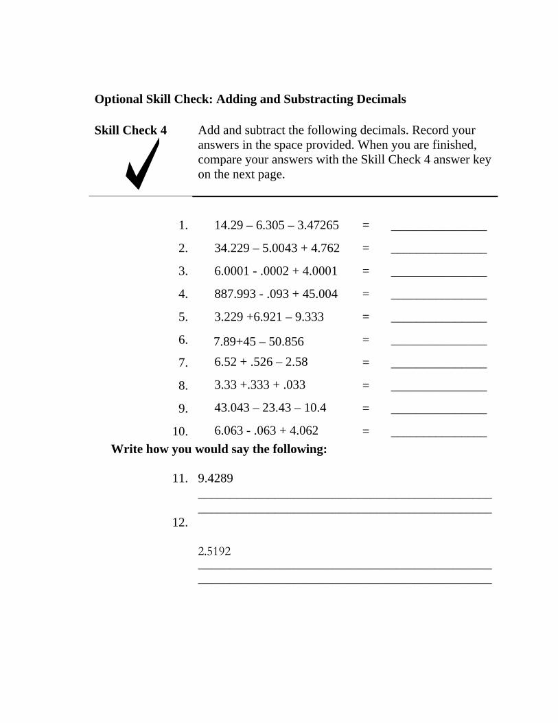
Optional Skill Check: Adding and Substracting Decimals
Add and subtract the following decimals. Record your answers in the space provided. When you are finished, compare your answers with the Skill Check 4 answer key on the next page.
Skill Check 4
1. 14.29 – 6.305 – 3.47265
2. 34.229 – 5.0043 + 4.762
3. 6.0001 - .0002 + 4.0001
4. 887.993 - .093 + 45.004
5. 3.229 +6.921 – 9.333
6. 7.89+45 – 50.856
7. 6.52 + .526 – 2.58
8. 3.33 +.333 + .033
9. 43.043 – 23.43 – 10.4
10. 6.063 - .063 + 4.062 Write how you would say the following:
11. 9.4289
= _______________
= _______________
= _______________
= _______________
= _______________
= _______________
= _______________
= _______________
= _______________
= _______________
12.
2.5192

Optional Skill Check Answers: Adding and Substracting Decimals
Skill Check 4 Answers
1. 14.29 – 6.305 – 3.47265
2. 34.229 – 5.0043 + 4.762
3. 6.0001 - .0002 + 4.0001
4. 887.993 - .093 + 45.004
5. 3.229 +6.921 – 9.333
6. 7.89 +45 – 50.856
7. 6.52 + .526 – 2.58
8. 3.33 +.333 + .033
9. 43.043 – 23.43 – 10.4
10. 6.063 - .063 + 4.062 Write how you would say the following:
11. 9.4289
= 4.51235
= 33.9867
= 10.
= 932.904
= .817
= 2.034
= 4.466
= 3.696
= 9.213
= 10.062
Nine inches, four-hundred twenty-eight thousandths and nine-tenths
12. 2.5192
Two inches, five-hundred nineteen-thousandths and two-tenths.

Summary During this section you were introduced to Decimals and Tolerances. You learned that whole numbers are placed to the left of the decimal. Fractions (tenths, hundredths, and thousandths are placed to the right of the decimal.
You practiced using a Decimal Equivalents Card for converting fractions to decimals.
You also practiced adding and subtracting decimals.
You were introduced to the concept of tolerances and methods to determine tolerance ranges.
If you are comfortable with this section, proceed to the next. Otherwise, review this section and ask your facilitator for further assistance, if necessary.

S E C T I O N 2 : U S I N G A S C A L E
Introduction Many manufacturing jobs require you to perform measurements using a scale. In this section you will:
• Learn how to read a scale • Measure several manufacturing parts • Perform five Skill Checks
Objectives At the end of this section, you will be able to: • Use a Scale to measure specific manufacturing parts
in inches.
Resources • Twelve-Inch Scale • Sharpened pencil • Various manufacturing parts

Introduction In this section you will be using a Twelve-Inch Scale.
Most scales have fractions marked on one face (halves, quarters, sixteenths of an inch) and decimals marked on the other face (tenths and hundredths of an inch). Since Engineering drawings use decimals, we will be using the face that is marked with decimal measurements.
Decimal
Fractional
Figure 3-1: Scale dimensions on each side of the scale

Reading the Study the figure below to become familiar with the Scale graduations on a scale.
Tenth Inch (.2) (1)
(.2) (.64) (2) Tenth Hundredth Inch
Figure 3-2: Decimal Graduation on a Scale.
Reading the Decimal Scale
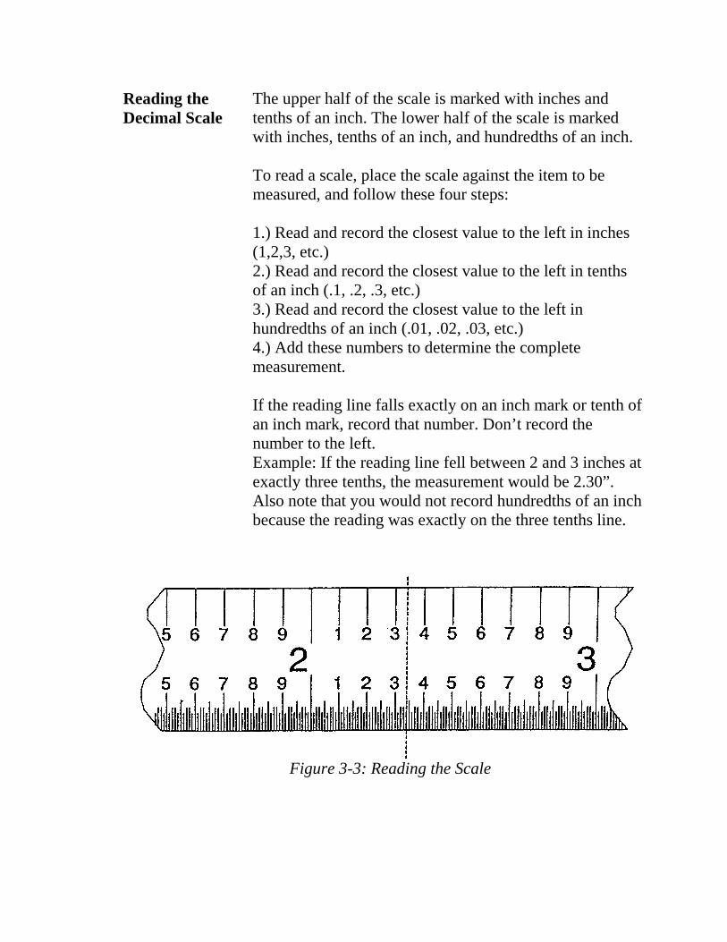
The upper half of the scale is marked with inches and tenths of an inch. The lower half of the scale is marked with inches, tenths of an inch, and hundredths of an inch.
To read a scale, place the scale against the item to be measured, and follow these four steps:
1.) Read and record the closest value to the left in inches (1,2,3, etc.) 2.) Read and record the closest value to the left in tenths of an inch (.1, .2, .3, etc.)3.) Read and record the closest value to the left in hundredths of an inch (.01, .02, .03, etc.) 4.) Add these numbers to determine the complete measurement.
If the reading line falls exactly on an inch mark or tenth of an inch mark, record that number. Don’t record the number to the left. Example: If the reading line fell between 2 and 3 inches at exactly three tenths, the measurement would be 2.30”. Also note that you would not record hundredths of an inch because the reading was exactly on the three tenths line.
Figure 3-3: Reading the Scale
Practice Reading the Decimal Scale
Refer to Figure 3-3. Looking at the upper half of the scale, notice that the reading is between 2 and 3 inches. Record the number to the left, which is 2.0. The reading so far is 2.0 inches.
Looking closer, you can also see that the reading is between the 3 tenths and 4 tenths marks (between .3 and .4). Record the number to the left of the reading, which is .3. You now know that the reading is a little more than 2.3 inches.
Now look at the bottom edge of the scale for a more precise measurement. The smallest graduation marks are hundredths of an inch. The reading aligns with the fourth mark after 2.3, which is four one hundredths of an inch, or .04”. That means that the reading is 2.34”.
2.0 .3 .04 2.34
If a dimension requires a measurement in thousandths of an inch, you will need to use a more precise measuring tool than a scale.

Steps to follow when reading a scale
Skill Check 1
To read a scale, follow these steps:
1. Read and record the next lower inch value (1.0) 2. Read and record the next lower tenths value (.1) 3. Read and record the next lower hundredth value (.01)
Remember, if the reading line is exactly on an inch, tenth or hundred, that is the number you record, not the next lower one.
Calculate the reading on the scale below and record your answer on the line below.
Answer: _________________
Compare your answer with the answer key on the next page.

Skill Check 1 Answer
The correct reading is 4.78.

Skill Check 2 Below is a scale with arrows pointing to several locations on the scale. Read the scale and record your answer on the corresponding line. When you have finished, check your answers on the following page.
Record your measurements here:
A. ____________
B. ____________
C. ____________
D. ____________
E. ____________
F. ____________
G. ____________
H. ____________
I. ____________
J. ____________
K. ____________

Skill Check 2 Check your answers. If you missed more than 3, review the previous section before proceeding. It will help you to understand the rest of this section.
Answers
A. .90 E. .81 I. 2.55 B. 2.80 F. 1.37 J. 2.73 C. .26 G. 1.59 K. 2.96 D. .57 H. 2.12
Notice that zeroes have been added to the end of some of the answers. Remember that this does not change the value of the numbers.
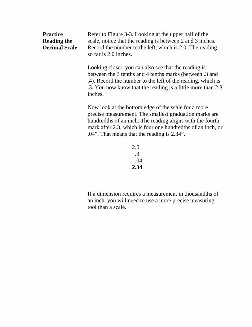
Taking Readings with a Scale
Once you know how to read the scale, you can use it to measure between lines: 1. Set the scale so that the zero end of the scale is even
with the first line, as in figure 3- 4. 2. Read the scale values that line up with the reading
line, which is behind the scale. 3. Record your reading.
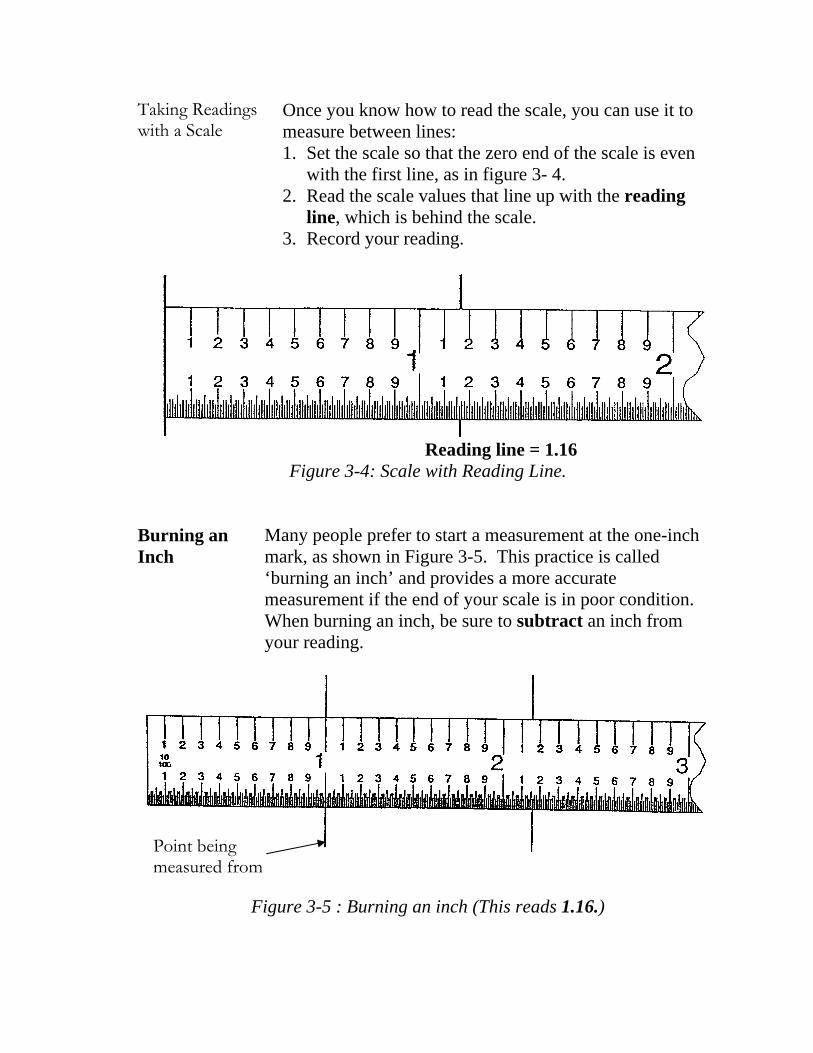
Burning an Inch
Reading line = 1.16 Figure 3-4: Scale with Reading Line.
Many people prefer to start a measurement at the one-inch mark, as shown in Figure 3-5. This practice is called ‘burning an inch’ and provides a more accurate measurement if the end of your scale is in poor condition. When burning an inch, be sure to subtract an inch from your reading.
Point being measured from
Figure 3-5 : Burning an inch (This reads 1.16.)
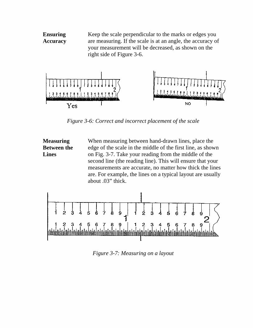
Ensuring Keep the scale perpendicular to the marks or edges you Accuracy are measuring. If the scale is at an angle, the accuracy of
your measurement will be decreased, as shown on the right side of Figure 3-6.
Figure 3-6: Correct and incorrect placement of the scale
Measuring When measuring between hand-drawn lines, place the Between the edge of the scale in the middle of the first line, as shown Lines on Fig. 3-7. Take your reading from the middle of the
second line (the reading line). This will ensure that your measurements are accurate, no matter how thick the lines are. For example, the lines on a typical layout are usually about .03” thick.
Figure 3-7: Measuring on a layout
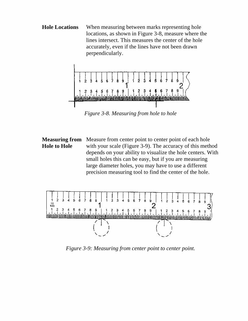
Hole Locations When measuring between marks representing hole locations, as shown in Figure 3-8, measure where the lines intersect. This measures the center of the hole accurately, even if the lines have not been drawn perpendicularly.
Measuring from Hole to Hole
Figure 3-8. Measuring from hole to hole
Measure from center point to center point of each hole with your scale (Figure 3-9). The accuracy of this method depends on your ability to visualize the hole centers. With small holes this can be easy, but if you are measuring large diameter holes, you may have to use a different precision measuring tool to find the center of the hole.
Figure 3-9: Measuring from center point to center point.
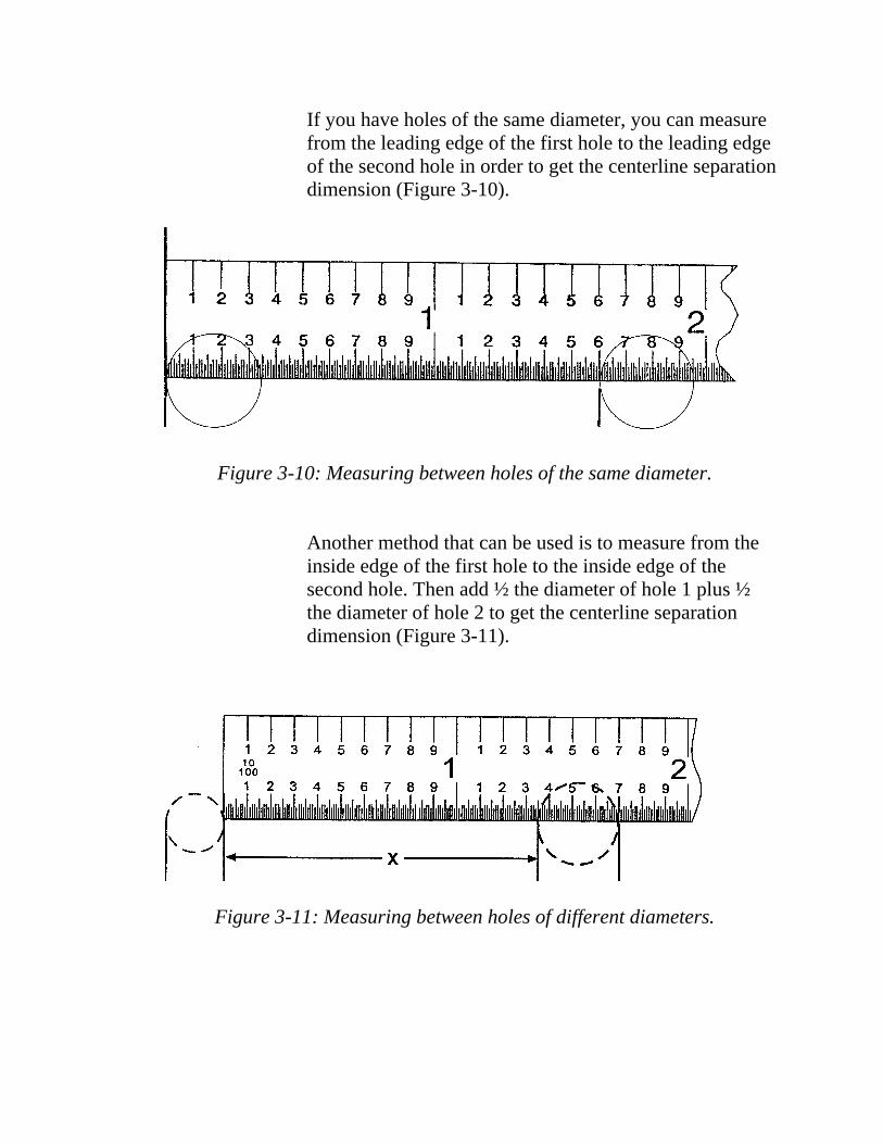
If you have holes of the same diameter, you can measure from the leading edge of the first hole to the leading edge of the second hole in order to get the centerline separation dimension (Figure 3-10).
Figure 3-10: Measuring between holes of the same diameter.
Another method that can be used is to measure from the inside edge of the first hole to the inside edge of the second hole. Then add ½ the diameter of hole 1 plus ½ the diameter of hole 2 to get the centerline separation dimension (Figure 3-11).
Figure 3-11: Measuring between holes of different diameters.

Skill Check 3 Measure the ten lines on this page and record your answers in the spaces below. When you are done, check your answers with the answer key on the following page.
1. 2.
3.
4.
5.
6.
7.
8.
9.
10.
1. ________________
2. ________________
3. ________________
4. ________________
5. ________________
6. _________________
7. _________________
8. _________________
9. _________________
10._________________

Skill Check 3 Check your answers from the previous page. Did you get them all right? If you did, great! If not, you might want to go back and check your answers before moving on to the next section.
Answers
1. .620 6. 1.990
2. .770 7. 2.360
3. .930 8. 2.830
4. 1.270 9. 3.470
5. 1.760 10.4.180
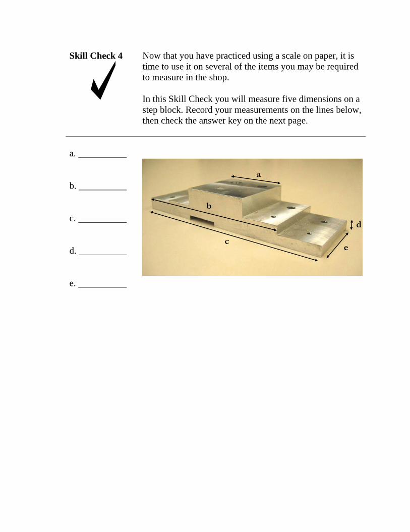
Skill Check 4 Now that you have practiced using a scale on paper, it is time to use it on several of the items you may be required to measure in the shop.
In this Skill Check you will measure five dimensions on a step block. Record your measurements on the lines below, then check the answer key on the next page.
a.
b.
c.
d.
e.
a
b
c
d
e

Skill Check 4 Check your answers from the previous page. If any of your answers are significantly different from the ones below, recheck your measurements before moving on to the next section. Ask your facilitator for assistance, if needed.
Answers
a. 2.000
b. 5.000
c. 6.100
d. .389
e. 2.000

Making Layouts with the Scale
A scale is useful for performing layouts that need only to be accurate to +/- .020. For example, a scale can be used to mark a hole pattern on a block in preparation for drilling.
Using Sketch 1 as a model, use the box in Sketch 2 to lay out a line, following the directions below.
.60 inch
Sketch 1
1. On the left side of the box below, measure .60 inches from the top of the box. Make a small mark at the .60 location.
2. Then, measure .60 inch from the top of the right side of the box and mark it as you did in step one.
3. Now align the edge of the scale with the two marks you just made. Use the edge of the scale to draw a line between the two marks.
Sketch 2

4. Have the facilitator check your work for accuracy. 5. Next you will draw vertical lines. First, lay out another
horizontal line at .60 inches, using the box in Sketch 4. 6. Now you will lay out 3 vertical lines in the Sketch 4
box that are 1.00”, 1.40”, and 2.40” long. To lay out vertical lines, start your measurement from the left side of the box. Use Sketch 3 as a model. Place the end of your scale on the left side of the box. Mark off 1.00” at the top and at the bottom of the box.
7. Now connect the marks by drawing a vertical line. Repeat the process to draw the 1.40” and 2.40” lines. Have the facilitator check your work for accuracy.
.60” 2.40”
1.40”
1.00”
Sketch 3: Laying out vertical lines
Sketch4
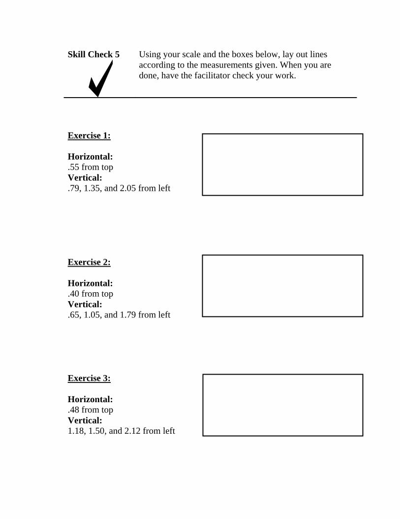
Skill Check 5 Using your scale and the boxes below, lay out lines according to the measurements given. When you are done, have the facilitator check your work.
Exercise 1:
Horizontal: .55 from top Vertical: .79, 1.35, and 2.05 from left
Exercise 2:
Horizontal: .40 from top Vertical: .65, 1.05, and 1.79 from left
Exercise 3:
Horizontal: .48 from top Vertical: 1.18, 1.50, and 2.12 from left
Summary In this section you were introduced to the scale as a tool used to perform measurements. You learned that the scale has two faces that are marked with decimals and fractions. You measured various objects and learned several techniques for measuring, including:
• Burning an inch • Measuring between lines • Measuring hole locations • Measuring from hole to hole
In this section you also learned how to make layouts with a scale.
If you are comfortable with using the scale, proceed to the next section. Otherwise, review any area that you had difficulty with or ask your facilitator for assistance.
S E C T I O N 3 : U S I N G S I X - I N C H D I A L C A L I P E R S
Introduction In this section you will learn how to read and use a Six-Inch Dial Caliper. The Dial Caliper is used to measure inside measurements, outside measurements, round stock, square stock, plates, counter bores, bushings and depths.
Objectives Each participant will be able to:
• Use a Six-Inch Dial Caliper to take inside and outside measurements that are accurate to within +/- .005.
• Demonstrate how to determine the accuracy of a Six-Inch Dial Caliper.
Skill Check At the end of this section, you will be expected to use a Six-Inch Dial Caliper to accurately measure objects to 3 decimal places.
Resources • Six-Inch Dial Caliper • Manufacturing parts to measure

Dial Caliper Introduction
A Six-Inch Dial Caliper is a precision-measuring tool that measures accurately to within .001 of an inch. Although it is not as accurate as a Vernier Scale Micrometer (which can read to within .0001 of an inch), the Six-Inch Dial Caliper is more versatile.
You can use the Six-Inch Dial Caliper to measure distance from 0 to 6 inches for inside, outside, and depth measurements. Because of its versatility, you will use this tool frequently.
A Dial Caliper has jaws that contact inside and outside surfaces during measurements, and a rod connected to a slide for obtaining depth dimensions. The end of the rod is notched to provide a nib for measuring small grooves and recesses.
All readings are taken directly from the bar and dial- indicator. Knurled thumbscrews lock the movable jaw and adjustable indicator dial.
With the addition of a depth attachment, the Dial Caliper becomes as convenient and easy to use as a depth gauge.
Dial Caliper Parts
E A
G
B C D
B C
F
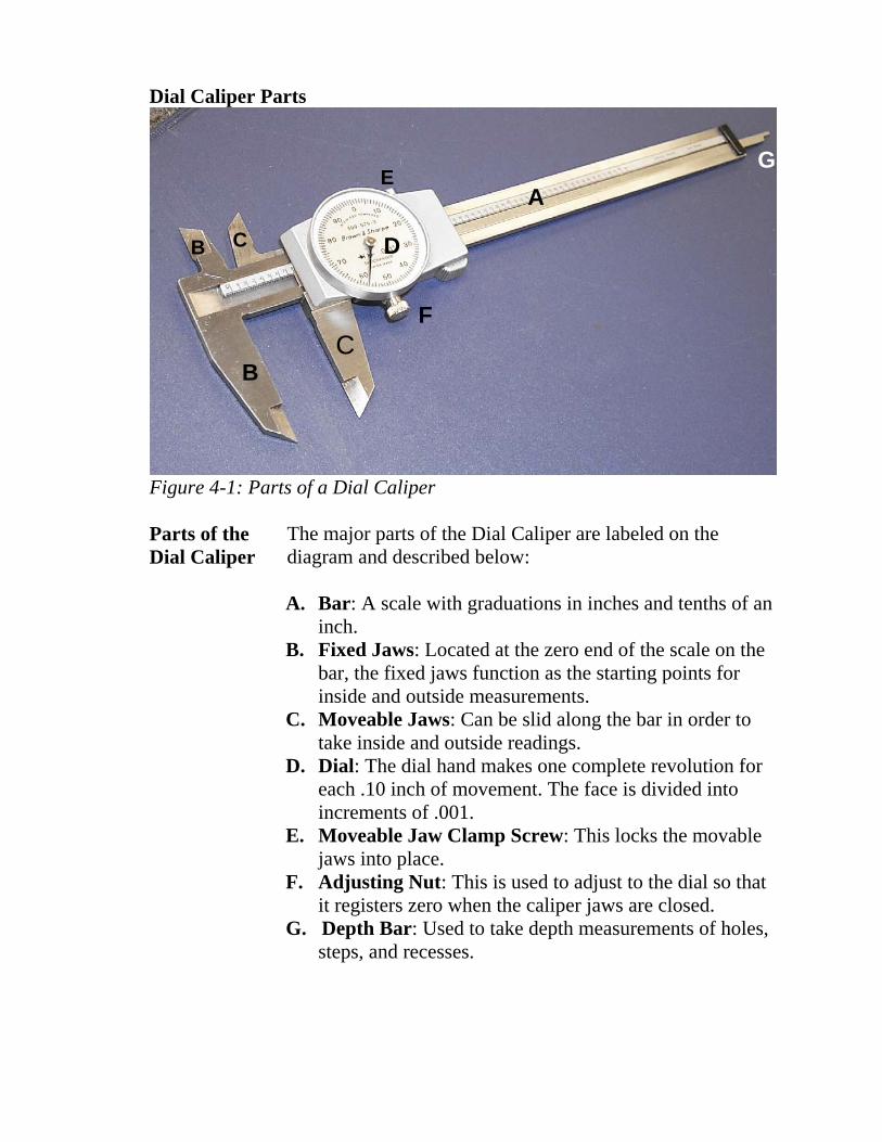
Figure 4-1: Parts of a Dial Caliper
Parts of the The major parts of the Dial Caliper are labeled on the Dial Caliper diagram and described below:
A. Bar: A scale with graduations in inches and tenths of an inch.
B. Fixed Jaws: Located at the zero end of the scale on the bar, the fixed jaws function as the starting points for inside and outside measurements.
C. Moveable Jaws: Can be slid along the bar in order to take inside and outside readings.
D. Dial: The dial hand makes one complete revolution for each .10 inch of movement. The face is divided into increments of .001.
E. Moveable Jaw Clamp Screw: This locks the movable jaws into place.
F. Adjusting Nut: This is used to adjust to the dial so that it registers zero when the caliper jaws are closed.
G. Depth Bar: Used to take depth measurements of holes, steps, and recesses.

Reading the Dial and Bar
Once you have placed the jaws in the space or around the part that you want to measure, you need to read both the bar and the dial to get a reading.
The bar is in increments of inches and tenths. As you slide the bar to the right, new increments appear from under the dial. In Figure 4- 2, the reading is something over .700”.
Figure 4-2. Reading the bar and dial
One full rotation of the dial (zero to zero) represents a movement of .100 inch. The dial reads in thousandths and ten thousandths. In Figure 4-2, the last line visible on the bar is .700 and the dial reads .050, so the reading on this measurement is .750.
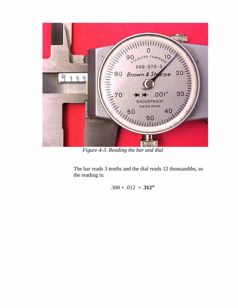
Figure 4-3. Reading the bar and dial
The bar reads 3 tenths and the dial reads 12 thousandths, so the reading is:
.300 + .012 = .312”

_________
__________
Skill Check 1 Read the bar and dial in each photo below, then record your reading in the space provided. When you are done, check your answers with the answer key following this Skill Check.
Dial Caliper
1.
2.

_______
_______
_______
3.
4.
5.

_______
_______
_______
6.
7.
8.

_______
_______
_______
9.
10.
11.

Skill Check 1 Below are the answers to the previous exercise. How did you do? If you missed more than 3 you may want to do a little more practice reading the dial. If you got them all right, congratulations!
Answers
1. .966 2. .357 3. .665 4. .485 5. 1.003 6. 1.321
7. 1.100 8. .927 9. 1.490 10. 1.173 11. 1.962
Types of Measurement Using a Dial Caliper
Outside Measurement
Dial calipers can perform three types of measurements: • Outside surfaces • Inside surfaces • Depth measurements
Each of these measurements is taken with the inside or outside jaws or the depth bar.
Note: Always make sure that the object you want to measure is clean and free of burrs, or your measurement will not be accurate.
Perform the following steps to measure the outside diameter of an item from your kit:
1. Place your left hand on the fixed jaws. Place your right hand around the bar with your thumb on the sliding bar.
2. With your right-hand thumb, slide the movable jaw away from the fixed jaw.
3. Slide the movable jaw out until the opening between the jaws is slightly larger than the width of the item you are measuring.
4. Hold the item against the fixed jaw and slide the movable jaw inward until the movable jaw is touching the item.
5. Rock the caliper slightly to make sure it is perfectly square on the item, while adjusting for final feel and setting.
6. The measuring surfaces of the caliper must be square on the material in order to get an accurate measurement.
7. Read the measurements on the bar and the dial.

Figure 4-4: Incorrect and correct placement of calipers
Caring for Dial Calipers must be handled with care to preserve their the Dial accuracy. Some of the things you can do to increase the life Caliper of your calipers include:
• Keep your calipers and measuring surfaces clean.
• Keep your calipers in a case, with the jaws slightly open. If they are stored in the closed position, condensation may form, causing the surface to corrode, and destroying the caliper’s accuracy.
• Regularly check to see that zero lines on the caliper scales align when the jaws are closed.
• Keep your tool certification up to date. All calipers used in critical applications must be certified. Most tool room personnel can address your certification requirements.
How to Check the Accuracy of the Dial Caliper
Ensuring Accuracy
Checking the accuracy of the Dial Caliper requires a few simple steps:
1. Ask your classroom facilitator for a gauge block with a known thickness.
2. Place the gauge block in the jaws and measure the gauge block.
3. If the reading doesn’t correspond with the gauge block thickness, use the caliper adjustment knob to move the dial until it corresponds with the thickness of the gauge block. This will reset the Dial Caliper.
Perform the following steps before using your calipers:
• Check your gauge block reading. Have the facilitator verify that you are making the correct reading.
• Ensure that the surfaces of the caliper are clean. • Verify that the zero lines on the scale align when the
jaws are closed. If they do not, return the caliper to the classroom facilitator and get another one.
• Check that the sides of the block are clean. • Measure the block again by repeating the procedure.
When measuring round objects, you need to be especially careful about holding the caliper jaws square to the surface of the object. You are looking for the smallest reading you can get without forcing the caliper jaws hard against the object.

Skill Check 2 Use the corresponding materials from your kit to perform the measurements indicated. Record your dial caliper measurements in the spaces provided. When you are done, check your answers with your classroom facilitator.
Large & Small Large: Dowel Pins A. _________
B. _________
Small:
C. _________
D. _________
BA
C D
Large: Large & Small A. _________ Locating Pin
Liners B. _________
Small:
C. _________
D. _________
A
B
C
D

A. _________ Plate
B. _________
C. _________ A
C B

Skill Check 2 Check your numbers with the answers below. If any of Answers your answers are significantly different, re-measure the
material and check your answer again. Ask the facilitator for assistance, if needed.
Large: A. _ .375___
B. _2.000 __
Small:
C. _ .187___
D. _2.000___
Large & Small Dowel Pins
Large: A. _.501__
B. _.620 _
Small:
C. _.407__
D. _.560__
Large & Small Locating Pin Liners
Plate A. _ .125___
B. _1.700 to 2.000__
C. _1.700 to 2.000__

For Inside Measurements
Figure 4-5:Caliper jaws used for inside measurement.
Inside To take an inside measurement, follow the same procedures Measurement as the outside dimension method, but use the inside jaws of
the calipers (Figure 4-5).
To measure inside diameter:
1. Select one of the bushings from your materials kit. Measure the hole in either end of the bushing:
2. Slide the movable jaw so that points of the inside jaws are open a little less than the hole to be measured in the bushing.

3. Use your thumb to pull the movable jaw out until it just touches the side of the bushing.
4. Rock the caliper slightly, moving one end of the caliper gently back and forth. You are looking for the largest reading you can get without forcing the jaws against the bushing. There should only be a very slight resistance between the jaws and the surface of the bushing. (See Figure 4-6.)
5. Once you have achieved the proper feel of the jaws in the bushing, snug down the moveable jaw clamping screw.
6. Read the bar scale and the dial to determine the measurement.
Figure 4-6: Incorrect and correct placement of caliper jaws

Skill Check 3 Record the dial caliper measurements for your bushing, as indicated below. When you are done, check your measurements with the answers on the following page.
1. ___________ Slot Side
2. ___________ Flat Side
3. ___________ Outside Slot

Skill Check 3 Check your numbers with the answers below. If any of your answers are significantly different, re-measure the material and check your answer again. Ask the facilitator for assistance, if needed.
Answers
1. __.406_____ Slot Side
2. ___.250____ Flat Side
3. ___.063____ Outside Slot

Taking a The depth-measuring device on a Dial Caliper consists of an Depth adjustable rod, called the depth bar. The depth bar extends Measurement from the end of the caliper bar.
Figure 4-7: Taking a depth measurement
The body of the dial caliper rests on a precision surface that functions as a fixed jaw for taking a depth measurement. The depth bar functions as the movable jaw.
The depth bar can measure the depth of holes, the height of steps, or the thickness of an object.
Using the Depth Bar
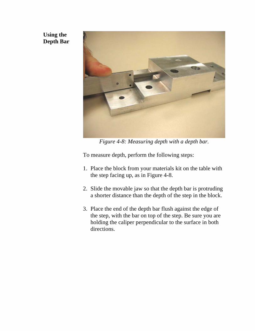
Figure 4-8: Measuring depth with a depth bar.
To measure depth, perform the following steps:
1. Place the block from your materials kit on the table with the step facing up, as in Figure 4-8.
2. Slide the movable jaw so that the depth bar is protruding a shorter distance than the depth of the step in the block.
3. Place the end of the depth bar flush against the edge of the step, with the bar on top of the step. Be sure you are holding the caliper perpendicular to the surface in both directions.

Figure 4-9: Correct placement of depth bar
4. Use your thumb to move the depth bar until it’s just touching the vertical surface, and snug down the movable jaw clamping screw.
5. Now read the dial and bar scale to determine the correct measurement.

The correct reading for the depth of the step shown in Figure 4-8 is .489”. Check with the facilitator if you did not get the correct reading,
• Check the caliper and the block for cleanliness.
• Try again, paying particular attention to keeping the caliper perpendicular to the work piece in all directions.
Any deviation from perpendicular reduces your accuracy. Because the end of the caliper is so small, it is often difficult to get an extremely accurate depth reading with it.

Measuring the Now let’s take a depth measurement of a hole. Depth of a Hole
Figure 4-10: Measuring a hole with the depth bar.
1. Place the block from your kit on the table.
2. Place the dial caliper so that the bottom edge is over a hole, as in Figure 4-10.
3. Slide the movable jaw until the depth bar is protruding into the hole, but not touching the bottom of the hole. The end of the caliper bar should be touching the surface of the block on either side of the hole.
4. Holding the caliper so that the end is flat against the surface of the block, gently slide the movable jaw downward until you feel the end of the depth bar just touch the surface of the table at the bottom of the hole. Do not allow it to push the end of the caliper bar away from the surface of the block.
5. Tighten the movable jaw clamping screw.
6. Read the bar scale and dial.
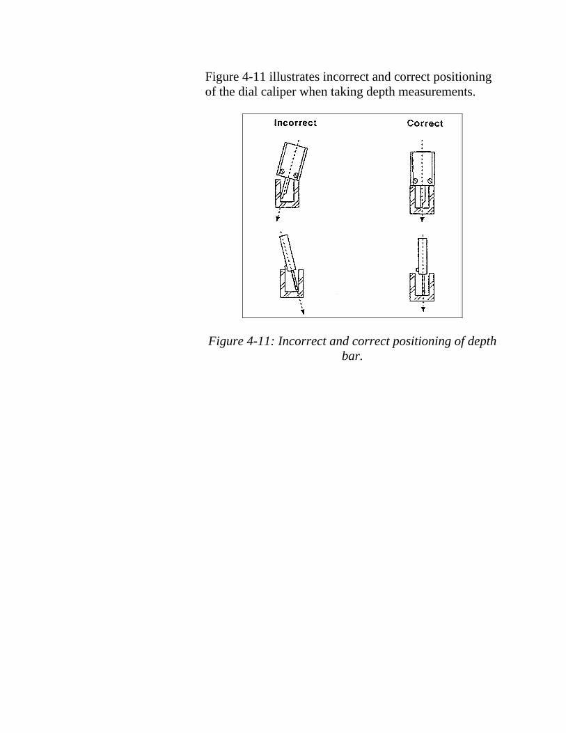
Figure 4-11 illustrates incorrect and correct positioning of the dial caliper when taking depth measurements.
Figure 4-11: Incorrect and correct positioning of depth bar.
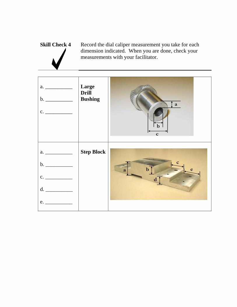
Skill Check 4 Record the dial caliper measurement you take for each dimension indicated. When you are done, check your measurements with your facilitator.
a. __________ Large Drill
b. __________
c. __________
Bushing a
b
c
a. __________ Step Block
b. __________
c. __________ d
ba
c e
d. __________
e. __________

Skill Check 4 Check your numbers with the answers below. If any of your answers are significantly different, re-measure the material and check your answer again. Ask the facilitator for assistance, if needed.
Answers
a. __.125____ Large Drill Bushing
b. _ .312____
c. _ .437____
a. __.980____ Step Block
b. __.485____
c. __.998____
d. __.481____
e. _1.113____

Summary In this section, you learned that the dial caliper can measure inside measurements, outside measurements, round stock, square stock, counter bores and depths. You were given several exercises, and then measured various items. You also read about the importance of keeping your dial caliper clean and in good working order.
Review any material that you found difficult. Ask your facilitator for any needed assistance.
When you are comfortable with using a dial caliper, proceed to the next section.

S E C T I O N 4 : M E A S U R I N G W I T H A N O U T S I D E M I C R O M E T E R
Introduction In this section you will learn how to measure using an outside micrometer. You will learn about the various functions of a micrometer, its components, and how to read the thimble and reading line.
Objectives At the end of this section you will be able to:
• Accurately measure objects to 4 decimal places. • Demonstrate how to determine the accuracy of a
micrometer.
Skill Check At the end of this section, you will be expected to use an outside micrometer to accurately measure objects to 4 decimal places.
Resources • 0 – 1 inch outside micrometer • Materials kit

Introduction to the 0-1 inch Outside Micrometer
The micrometer is a measuring tool designed to provide extremely accurate measurements (see Figure 5-1). Some micrometers can measure objects as small as ten-thousandths of an inch.
At the core of a micrometer is a large screw. Pitch is the distance between the peak of one screw thread to the peak of the next screw thread. The screw inside a 0-1inch outside micrometer has a pitch of forty threads per inch. One-fortieth of an inch is 0.025 (0.025” x 40 = 1.000”). This means that every time the micrometer handle (thimble) is turned one complete revolution around the central screw, it moves twenty-five thousands of an inch. This is how the internal screw of the micrometer is used as a precision measuring tool.
Figure 5-1: 0-1 inch outside micrometer
Although this class only uses the 0-1 inch outside micrometer, many other types of micrometers exist, including inside micrometers, and multi-anvil micrometers that can measure objects up to 60 inches.
The aircraft industry demands extremely high-quality measuring tools. They must to be certified by a company approved Calibration / Certification Lab, which tests and certifies that the measurements of the tools are correct. High quality tools will stay accurate and last much longer than cheaper versions.

Micrometer Components
This section section will cover the typical components of the 0-1 inch micrometer. In most cases, this information can be applied to other models.
Locate the following features on your micrometer:
Anvil The anvil is located at the end of the curved arm of the micrometer. It is a stationary component and provides a resting place for the material being measured.
Spindle The spindle is the other component that touches the material being measured. Turning the thimble moves the spindle toward or away from the anvil. The 0-1 inch outside micrometer measures distances between the anvil and the spindle, up to one inch.
Thimble Turning the thimble causes the spindle to go in or out. It has a textured grip so that your fingers will not slip.
Figure 5-2
Anvil Material Spindle
Sleeve Thimble Ratchet
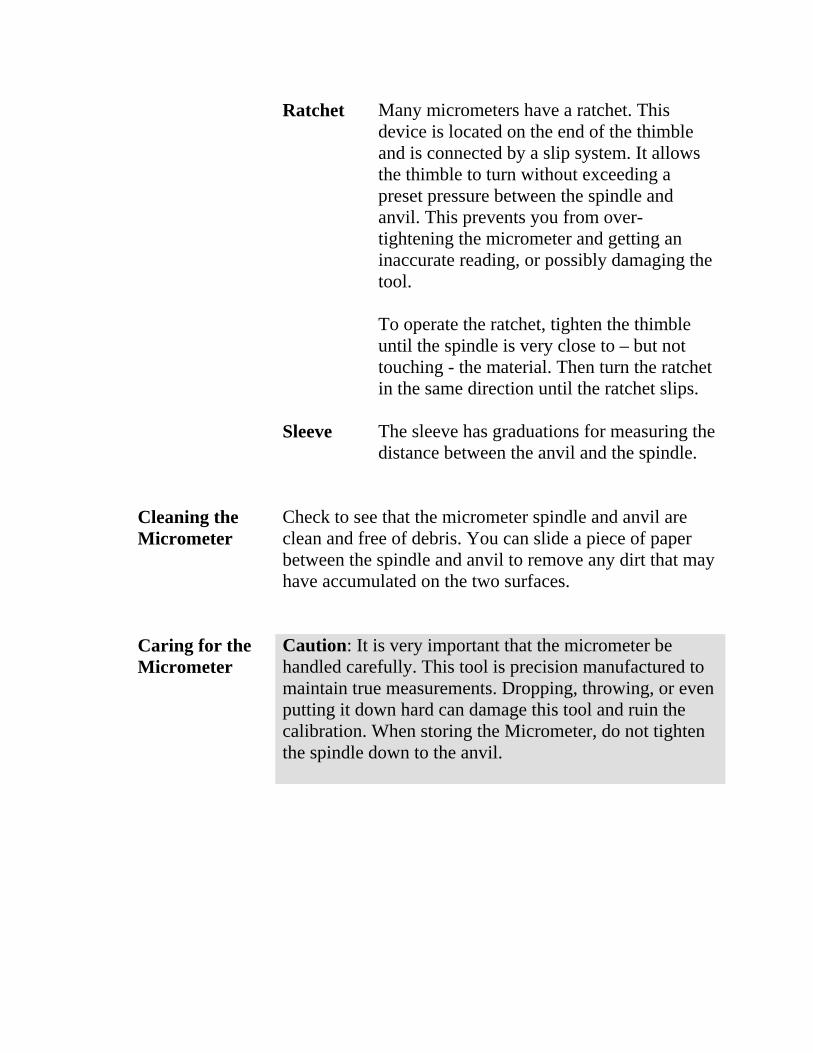
Ratchet Many micrometers have a ratchet. This device is located on the end of the thimble and is connected by a slip system. It allows the thimble to turn without exceeding a preset pressure between the spindle and anvil. This prevents you from overtightening the micrometer and getting an inaccurate reading, or possibly damaging the tool.
To operate the ratchet, tighten the thimble until the spindle is very close to – but not touching - the material. Then turn the ratchet in the same direction until the ratchet slips.
Sleeve The sleeve has graduations for measuring the distance between the anvil and the spindle.
Cleaning the Check to see that the micrometer spindle and anvil are Micrometer clean and free of debris. You can slide a piece of paper
between the spindle and anvil to remove any dirt that may have accumulated on the two surfaces.
Caring for the Caution: It is very important that the micrometer be Micrometer handled carefully. This tool is precision manufactured to
maintain true measurements. Dropping, throwing, or even putting it down hard can damage this tool and ruin the calibration. When storing the Micrometer, do not tighten the spindle down to the anvil.

______________________________________________________________
________________________________________________________
Skill Check 1 Label each of the micrometer components on the illustration below. Then write a brief description of the function of each component in the space provided.
1. _________
3. ________ 4. _________
5. __________ Material 2. __________
Write a brief description of the functions of each component.
1. ___________________________________________________________
2. ___________________________________________________________
3. ___________________________________________________________
4. ___________________________________________________________
5. ___________________________________________________________
6. How can you clean the spindle and anvil of a Micrometer?
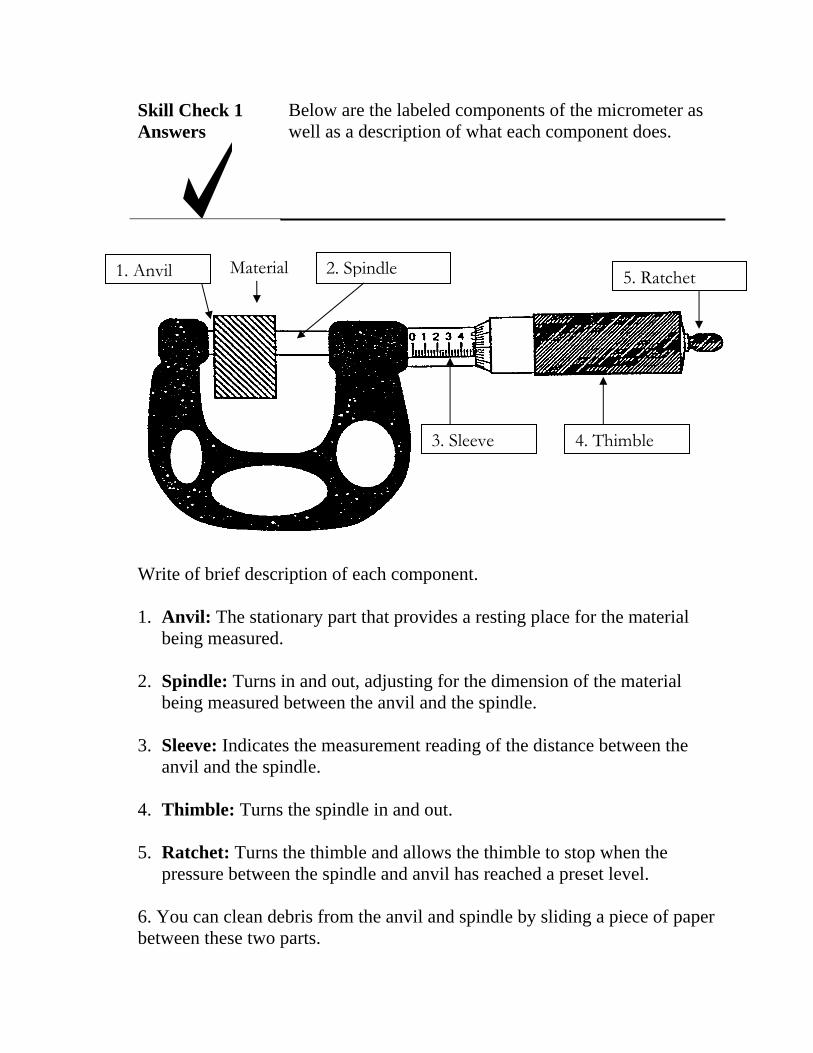
Skill Check 1 Below are the labeled components of the micrometer as Answers well as a description of what each component does.
1. Anvil Material 2. Spindle
3. Sleeve 4. Thimble
5. Ratchet
Write of brief description of each component.
1. Anvil: The stationary part that provides a resting place for the material being measured.
2. Spindle: Turns in and out, adjusting for the dimension of the material being measured between the anvil and the spindle.
3. Sleeve: Indicates the measurement reading of the distance between the anvil and the spindle.
4. Thimble: Turns the spindle in and out.
5. Ratchet: Turns the thimble and allows the thimble to stop when the pressure between the spindle and anvil has reached a preset level.
6. You can clean debris from the anvil and spindle by sliding a piece of paper between these two parts.
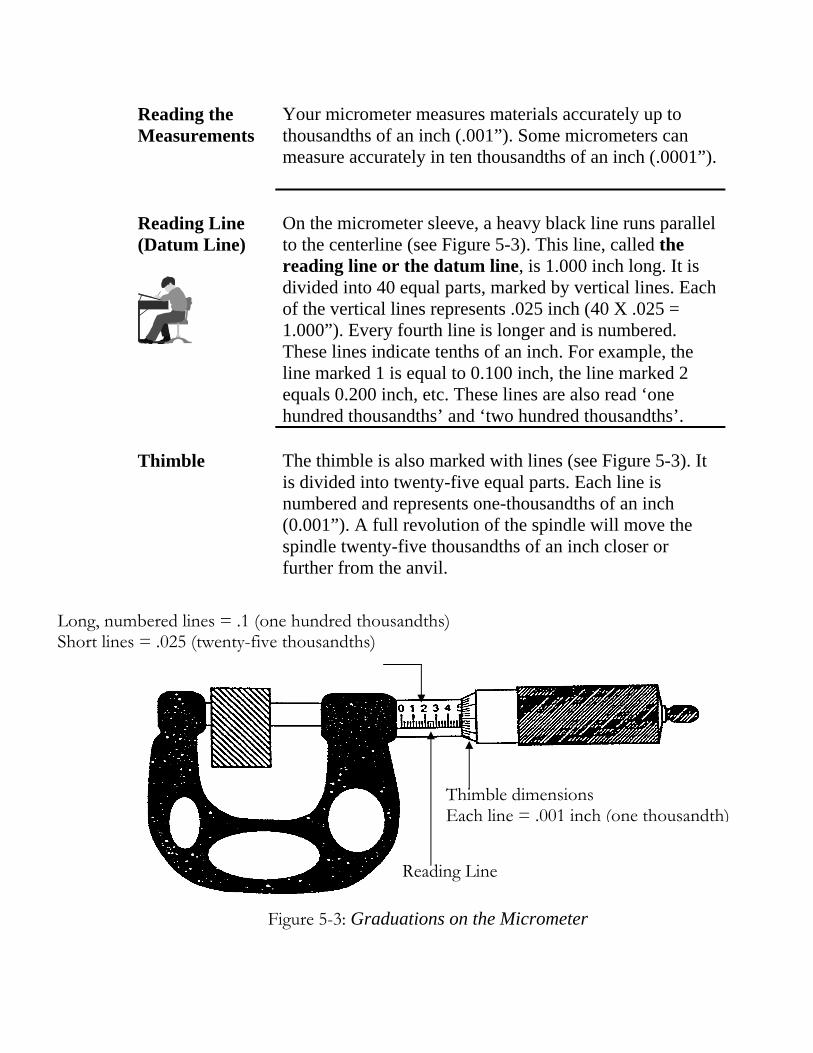
Reading the Your micrometer measures materials accurately up to Measurements thousandths of an inch (.001”). Some micrometers can
measure accurately in ten thousandths of an inch (.0001”).
Reading Line (Datum Line)
On the micrometer sleeve, a heavy black line runs parallel to the centerline (see Figure 5-3). This line, called the reading line or the datum line, is 1.000 inch long. It is divided into 40 equal parts, marked by vertical lines. Each of the vertical lines represents .025 inch (40 X .025 = 1.000”). Every fourth line is longer and is numbered. These lines indicate tenths of an inch. For example, the line marked 1 is equal to 0.100 inch, the line marked 2 equals 0.200 inch, etc. These lines are also read ‘one hundred thousandths’ and ‘two hundred thousandths’.
Thimble The thimble is also marked with lines (see Figure 5-3). It is divided into twenty-five equal parts. Each line is numbered and represents one-thousandths of an inch (0.001”). A full revolution of the spindle will move the spindle twenty-five thousandths of an inch closer or further from the anvil.
Long, numbered lines = .1 (one hundred thousandths) Short lines = .025 (twenty-five thousandths)
Reading Line
Thimble dimensions Each line = .001 inch (one thousandth)
Figure 5-3: Graduations on the Micrometer

Reading a Micrometer
Reading a micrometer involves the following steps:
Example 1 1. Place the material between the anvil and the spindle. 2. Move the spindle closer to the material by turning the
thimble, then the ratchet, until the material is in contact with both the spindle and the anvil. Do not over tighten.
3. Determine the measurement: a) Note the last visible numbered line on the sleeve. This
will indicate how many tenths of an inch are in the measurement. For example, if the last number visible is 2, note 0.200” (see Figure 5-4).
b) Look to see if any un-numbered lines are visible after the last number. If so, add 0.025 for each un-numbered line you see. We have already noted 0.200” on the sleeve in Figure 54. Now we add 0.025” for each of the lines visible past the ‘2’. There is only one un-numbered line visible to the right of the ‘2’, so we add 0.200 and 0.025:
0.200 0.025 0.225
Our reading for Figure 5-4 is 0.225”.
Figure 5-4: Taking a micrometer reading

Example 2 Refer to Figure 5-5. The last visible number on the spindle is 4, so we begin the reading by recording 0.400” Three smaller lines are visible to the right of the ‘4’ line, so we add 0.025” for each of those lines (3 X 0.025” = 0.075”). Adding 0.075 to 0.400 equals 0.475.
We can make the reading even more accurate by looking at the numbered lines on the thimble. We find the line on the thimble that lines up with the reading line on the spindle, and then we record the number on the thimble line.
In Figure 5-5 that number is 12, so we add 0.012 to our previous measurement (0.475) to get a total measurement of 0.487.
0.475 +0.012
0.487
Figure 5-5: Reading a micrometer thimble.

One Final Way to Read the Scale
Reading Ten-Thousandths
An easy way to read a Micrometer is to think of the numbers as currency – dollars and coins. Count the numbers on the sleeve as dollars, the un-numbered lines on the sleeve as quarters, and the lines on the thimble as cents. Then simply add up the ‘money’ and put a decimal point instead of a dollar sign in front of the sum.
To measure ten-thousandths of an inch with the 0-1 inch outside micrometer, look at the top of the sleeve and notice the horizontal ten lines that are parallel with the reading line. These numbered lines make up the vernier scale. To read this scale:
1. Find the line on the vernier scale that matches up with a line on the thimble. You may need to get a magnifying glass to clearly see which lines match.
2. Note the number of the matching thimble line. 3. Add this number, in ten thousandths, to your
micrometer reading.
For example, we have already determined a measurement of 0.487” from Figure 5-5. Figure 5-6 provides a close-up view of the same reading. Here we can see that a line on the vernier scale matches up with the thimble line marked ‘3’.
We record this vernier scale reading as 0.0003” (read as ‘three ten thousands’, or simply ‘three tenths’) and add that to our reading of 0.487” to get a final measurement of 0.4873”.
0.4870 +0.0003
0.4873

A line on the vernier scale matches up with line 3 on the thimble. This indicates .0003”. Add this number to your reading.
Figure 5-6: Reading ten-thousandths of an inch on a micrometer.
Summary: Calculating a micrometer reading
Record the last line visible on the sleeve in tenths of an inch. (If ‘0’, record as 0.000)................................ 0.400”
Record each un-numbered line as 0.025”.................. 0.075” (0.025” X 3)
Record the number on the thimble where the sleeve and thimble lines line up............................................ 0.012”
Add the three numbers to get the reading...………... 0.487”

Determining the Accuracy of a Micrometer
Before using a micrometer, it is first important to determine its accuracy:
1. First, validate the zero setting by closing the micrometer and ensuring that the reading is zero. If the micrometer doesn’t read zero, ask the facilitator for a replacement micrometer.
2. Next, obtain a gauge block from the facilitator.
3. Place the gauge block between the anvil and the spindle and turn the ratchet until the spindle is against the block.
4. Check the reading to see that it matches the known value of the gauge block.
If the reading does not match the gauge block within +/- .001, notify your course facilitator.
Measurement accuracy is critical. Determining the accuracy of a micrometer is easy to do and will help to ensure that your measurements meet all quality standards.

Skill Check 2 Micrometer Reading Part 2
Circle the correct answer for the following micrometer readings. Check your answers against the answer key on the page following these exercises.
1. a) 0.037 b) 0.303 c) 0.350 d) 0.375
2. a) 0.088 b) 0.113 c) 0.117 d) 0.138
3. a) 0.043 b) 0.068 c) 0.093 d) 0.122
4. a) 0.208 b) 0.233 c) 0.258 d) 0.262
5. a) 0.041 b) 0.044 c) 0.045 d) 0.091
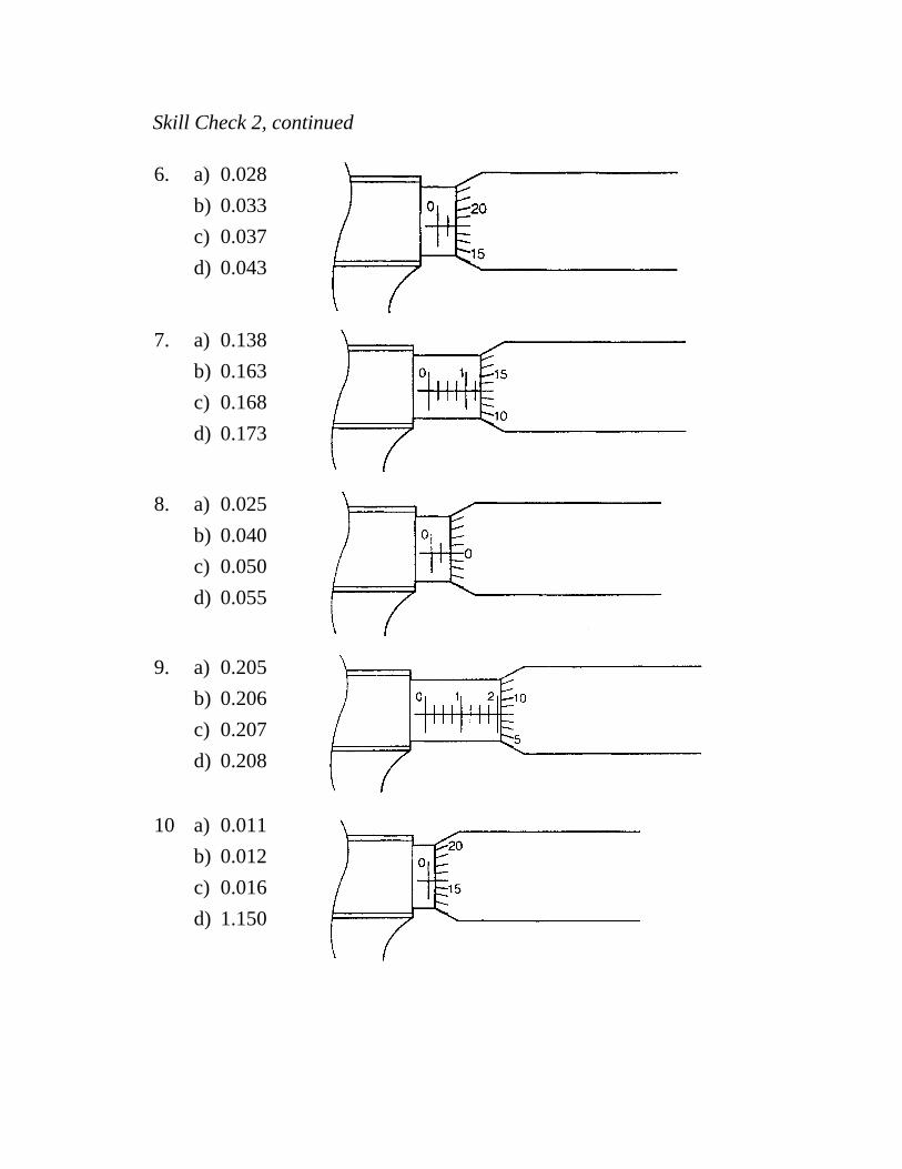
Skill Check 2, continued
6. a) 0.028 b) 0.033 c) 0.037 d) 0.043
7. a) 0.138 b) 0.163 c) 0.168 d) 0.173
8. a) 0.025 b) 0.040 c) 0.050 d) 0.055
9. a) 0.205 b) 0.206 c) 0.207 d) 0.208
10 a) 0.011 b) 0.012 c) 0.016 d) 1.150

Skill Check 2, continued
11 a) 0.195 b) 0.205 c) 0.230 d) 0.235
12 a) 0.220 b) 0.240 c) 0.245 d) 2.450
13 a) 0.052 b) 0.058 c) 0.062 d) 0.077
14 a) 0.201 b) 0.225 c) 0.230 d) 0.235
15 a) 0.052 b) 0.502 c) 0.548 d) 0.578

__________
__________
__________
__________
__________
Skill Check 2, continued
16
17
18
19
20

__________
__________
__________
__________
__________
Skill Check 2, continued
21
22
23
24
25
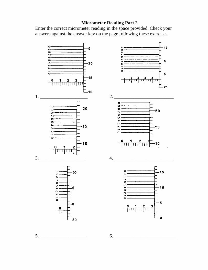
Micrometer Reading Part 2 Enter the correct micrometer reading in the space provided. Check your answers against the answer key on the page following these exercises.
1. ____________________ 2. _________________________
3. ___________________ 4. _________________________
5. ____________________ 6. __________________________

Skill Check 2 Below are the answers to the previous exercises. Check to see how you did. If you missed more than 3, reread the materials and check the readings again.
Answers
Micrometer Readings Part 1 1. d. 0.375 8. c. 0.050 15.
2. a. 0.088 9. d. 0.208 16.
3. c. 0.093 10. c. 0.016 17.
4. b. 0.233 11. b. 0.205 18.
5. d. 0.091 12. c. 0245 19.
6. d. 0.043 13. a. 0.052 20.
7. a. 0.138 14. d. 0.235 21.
Micrometer Readings Part 2
1. .3886
2. .4982
3. .2337
4. .3104
5. .0984
6. .3286
c. 0.548 22. 0.213
0.323 23. 0.300
0.195 24. 0.183
0.102 25. 0.141
0.285
a. 0.180
c. 0.118
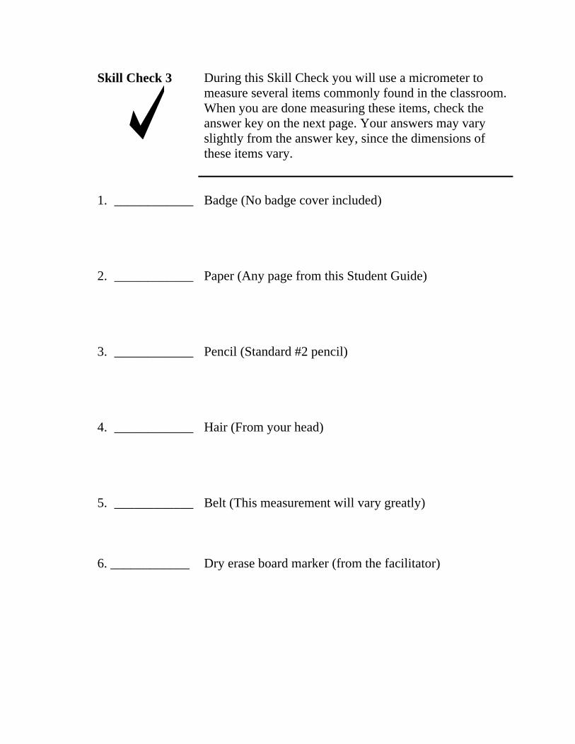
Skill Check 3 During this Skill Check you will use a micrometer to measure several items commonly found in the classroom. When you are done measuring these items, check the answer key on the next page. Your answers may vary slightly from the answer key, since the dimensions of these items vary.
1. ____________ Badge (No badge cover included)
2. ____________ Paper (Any page from this Student Guide)
3. ____________ Pencil (Standard #2 pencil)
4. ____________ Hair (From your head)
5. ____________ Belt (This measurement will vary greatly)
6. ____________ Dry erase board marker (from the facilitator)
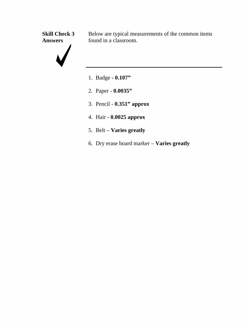
Skill Check 3 Below are typical measurements of the common items Answers found in a classroom.
1. Badge - 0.107”
2. Paper - 0.0035”
3. Pencil - 0.351” approx
4. Hair - 0.0025 approx
5. Belt – Varies greatly
6. Dry erase board marker – Varies greatly
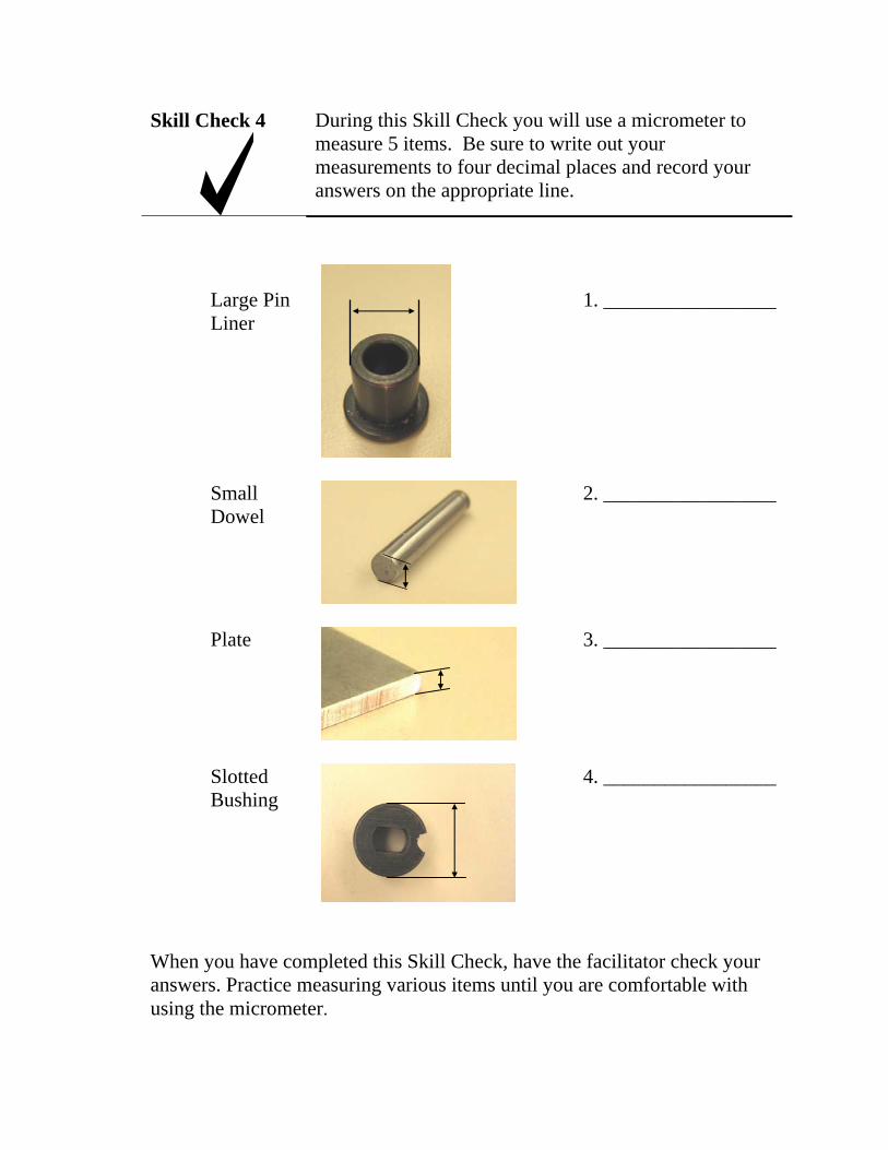
Skill Check 4 During this Skill Check you will use a micrometer to measure 5 items. Be sure to write out your measurements to four decimal places and record your answers on the appropriate line.
Large Pin 1. _________________ Liner
Small 2. _________________ Dowel
Plate 3. _________________
Slotted 4. _________________ Bushing
When you have completed this Skill Check, have the facilitator check your answers. Practice measuring various items until you are comfortable with using the micrometer.

Skill Check 4 Check your numbers with the answers below. If any of your answers are significantly different, re-measure the material and check your answer again. Ask the facilitator for assistance, if needed.
Answers
Large Pin 1. ____.501_________ Liner
Small 2. ___.187__________ Dowel
Plate 3. ___.125__________
Slotted 4. ____.406_________ Bushing

Summary In this section you were introduced to the Outside micrometer. You learned that the parts of the Micrometer include:
• Anvil • Spindle • Sleeve • Thimble • Ratchet
In this section you also learned how to read a micrometer to the nearest ten-thousandth of an inch. You were given several examples of micrometer settings and asked to record your readings. You were then given several items to measure.
If you are now comfortable with using the outside micrometer, proceed to the next section. Otherwise, review the material, and ask your facilitator for any needed assistance.

S E C T I O N 5 : B A L L G A U G E S
Introduction Ball gauges are not true precision measuring tool, but are used in conjunction with precision measuring tools, such as micrometers or calipers.
This section will explain how ball gauges work and their common uses.
Section The student will be able to take an accurate measurement Objective with a ball gauge and micrometer.
Skill Check At the end of this section, the student will be expected to properly use ball gauges to obtain accurate measurements.
Resources • Ball gauge set • Outside 0-1 inch micrometer

Using Ball Gauges with a Micrometer or Caliper
Ball gauges are most commonly used with other pieces of precision measurement equipment such as micrometers or calipers. They are used for taking measurements of .125” to .500” diameter holes. Although not true “calibrated” tools (tools that have been certified for accuracy by an approved certification lab), they should be treated with the same care afforded other precision measuring equipment.
Ball gauges are used to transfer the measurement of drilled holes ranging in size from .125” to .500”. They are normally issued in sets of four gauges that cover this range of measurements.
At the tip of the ball gauge is a split ball, which has a tapered cone inside that expands the ball when a knob is adjusted. Once the ball gauge is expanded to the fit the hole being measured, it is then removed from the hole and measured with a micrometer or caliper. These steps are outlined in greater detail below (see Figure 5-1):
Step 1. Select a ball gauge that is within the range of the hole to be measured.
Step 2. Insert the split ball end of the gauge into the hole and gently turn the adjustment knob to expand the ball until the ball makes contact with the sides of the hole.
Step 3. Rotate the gauge at least ninety degrees to determine if the hole is out of round. If the sides of the split ball do not continually contact the sides of the hole as the gauge is rotated, the hole is either out of round or angled.
Step 4. Remove the Ball Gauge from the hole, being careful not to change the setting.
Step 5. Measure the widest diameter of the split ball with a micrometer or caliper and record the measurement.

Ball Gauges
Adjustment Knob
Split Ball
Tapered Cone
Figure 5-1: Measuring a hole with a ball gauge.
Note: When storing ball gauges, be sure to reset the split ball to its minimum diameter.

Skill Check 1 For each question, select the correct answer from the list. Check your answers with the key on the next page.
1. Ball Gauges are most often used to measure holes that are within which diameter range?
a) .125 to .500 inches b) .125 to 1.00 inches c) .250 to .750 inches d) 1.00 to 5.00 inches
2. To determine if a hole is out of round or angled, the ball gauge should be rotated in the hole at least:
a) 30 degrees. b) 60 degrees. c) 90 degrees. d) 180 degrees.
3. Ball gauges can be used in conjunction with what precision measuring tools?
a) Micrometers b) Calipers c) Steel Rulers d) Both a & b
5. If the micrometer you are using has a ratchet on the thimble, you should always use it.
a ) True b) False
Skill Check 1 Check to see how you did on the previous Skill Check. If you missed any of the questions, return to the information in this section and review the material.
Answers
1. (a) .125 & .500 inches
2. (c) 90 degrees
3. (d) Both a & b
4. False

2 Skill Check Locate the step block in your materials kit and measure the
holes indicated in Figure 5-2 to the nearest thousandths of an inch (.001”). Record your readings in the spaces provided. When you have finished, check your answers with the answer key on the next page.
a.
b.
c.
d.
e. f.

Skill Check 2 Answers
Check to see how you did on the previous Skill Check. If your answers are significantly different than the ones on this answer key, review this section and measure the holes again. Ask your facilitator for assistance, if needed.
a. .187
b. .444
c. .156
d. .414
e. .379
f. .315
Congratulations! You have completed the self-paced portion of Precision Measuring Tools- Basic. You are now ready to take the Final Test.
Please review this material until you are comfortable with each section. Refer any questions to the facilitator.
When you are ready for the Final Test, ask the facilitator for the test booklet. This is a closed book test.