composites - amazon web servicessnocamp.s3.amazonaws.com/snocamp/uploads/files/... ·...
TRANSCRIPT

Experiments/Demonstrations
Composites


U.S. Department of Energy, Pacific Northwest National Laboratory 8.1
CompositesIntroductionA composite material is a combination of two or more separate materialsthat has characteristics not shown by either of the materials separately.An automobile tire, for instance—an example of a composite material—is made of rubber reinforced by one or more types of fibers, such asnylon, rayon, steel, glass, or Kevlar. The rubber does a fine job ofkeeping the pressurized air inside, but would not survive the stressesimposed on it by the car as it is driven. The fibers are strong and tough,but it would be impossible for a structure made only from the fibers tohold air. Together, the materials form a composite structure that bothholds air and resists stresses.
Looking more closely at the composition and structure of the tire tread,we can see that it too is a composite. The rubber provides a high frictionforce, very handy to have in the case of a car. A pure rubber tire wouldn’tlast very long, because the material is not very strong and becomesgummy when heated. Tiny balls of carbon known as carbon blackreinforce the rubber and give it resistance to wear. Tire rubber com-pounds represent a trade-off between friction and durability, thesefactors being adjusted by the relative amounts of rubber and carbonblack.
Composite materials have been around for a long time. Wood, anatural composite, is composed of cells made from cellulose fibersand bound together with a natural glue called lignin. If dried wood isexamined under a microscope, the cellular arrangement becomesobvious. Although wood can be split parallel to these long cells, it isstrong with the grain. The air spaces provided inside the cells of driedwood make it light in weight. This arrangement contributes to highstrength at low weight and to toughness.
In the thirteenth century, the Mongols made composite bows fromcombinations of wood, animal tendons, silk, and adhesives. Evenbefore that time, the Hebrew people added straw to their clay bricksto increase their durability.
Concrete is another example of a composite, and it has been madesince Roman times. The rocks and sand are the reinforcement partof this composite, and the cement provides the cohesion that bindsthe structure/material together.
In addition to these “old” composites, the drive for stronger, stiffer,and lighter materials has produced many more modern compositesof even higher performance such as tennis racquets, fishing poles,aircraft, space and automobile parts, and hulls of boats.

8.2 U.S. Department of Energy, Pacific Northwest National Laboratory
At the heart of any composite, a strong fibrous material bears the load.The fiber is constrained by the second material in the composite (thematrix) such that it takes the desired shape. Modern fishing rods arealmost universally made from composites, whether the reinforcingfibers are glass, graphite, boron, or a mixture of these materials. Thefibers, although strong, are not very stiff because they are very smallin diameter, less than one-thousandth of an inch. By adding a matrixmaterial, which is usually some type of epoxy in the case of the fishingrod, the fibers are tied together so that stress can be transferred fromone fiber to another and so the fibers share the load. To further lightenthe rod, it is made with a hollow core and is tapered so that the handleis thicker than the tip.
Most composites are used to make “things” that require high values ofmechanical properties such as strength (resistance to breakage) orstiffness (resistance to bending) at a minimum weight. In these roles,composites can be made superior to structures made from any singlematerial.
Modern composites use started with fiberglass in 1930, which is madefrom fine glass fibers bonded in most cases by polyester resin. Theglass fibers are very strong in tension, and the resin helps to definethe shape, bonds well to the fibers, and prevents the fibers fromdamaging each other by rubbing against their neighbors. Currently,many different types of fibers are available; the fibers are often quiteexpensive but are worth the price when the alternatives are consid-ered. As more and more composite materials are used, the price willdrop or become more compatible. Example: Some racquets, whenthey first came out, were $280 and now sell for $35.
A few years ago, composites were used only in parts of airplaneswhere their complete failure would have caused no serious problems.As confidence and reliability continues to increase, composites arebeing used in increasingly critical applications. Currently, several criti-cal parts of passenger airliners are made from composites; some mili-tary airplanes are made largely from composites. Building the Voyager,the airplane that flew around the world without refueling in 1986,would have been impossible without modern composite materials.
Composites Introduction

U.S. Department of Energy, Pacific Northwest National Laboratory 8.3
Composites Making Concrete
Making ConcreteInstructor Notes
ReliabilityThis lab is designed to be experimental with lots of room for makingmistakes and changes and testing the effects these cause. Thesuccess rate is determined by the care used in measuring and mixingingredients.
Teacher Tips 1. Concrete is a composite material made from sand, rocks (aggre-
gate), and cement. Students are familiar with this material butmany have never made concrete and may not know how itcements itself together. Thousands of different kinds of concreteare used for many different applications. It would take much studyto understand the many different compositions, reactions, andapplications of this material.
2. Portland cement forms hydration bonds as it is setting in the con-crete matrix. This means that the water added to the cement takespart in a reaction with the cement particles. The water forms astrong bond with the cement, and the cement particles are lockedtogether in an intertwining matrix. Cement does not dry, it cures.Another way to put it is that the water does not evaporate, itbecomes part of the concrete composite. Once concrete is formedit is very difficult to break and impossible to reverse the processback to the original materials. Hydration in concrete forms verystrong bonds.
3. This lab is divided into two parts: First, have all students makecement so they become familiar with the material. Second, allowstudents to vary compositions to determine how these changesaffect the concrete. Students can begin by making a commonconcrete from Portland cement. The composition of concretemade from Portland cement can vary also, so first try a commoncomposition of 40/60 weight percent sand to rock ratio and a 45/55 weight percent water to cement ratio.
4. Once students have learned how to work with concrete, they cando some scientific exploration. By altering the composition of con-crete, the properties of the material will also be altered. Testingand evaluating these changes is part of the work of a scientist.Encouraging students to follow the scientific process will helpthem learn, explore, evaluate, and be creative as they work withmaterials.

8.4 U.S. Department of Energy, Pacific Northwest National Laboratory
5. Test the samples following a test procedure, such as the onedescribed on the following page (see Testing Materials) andrecord both the procedure used and the test results.
Suggested Questions
6. What strengthens this material?
7. Are there other materials which could be added to concrete tostrengthen it? Try your theory by making and testing it.
8. Is there a better way to test concrete?
9. What is the best use for concrete materials?
Composites Making Concrete

U.S. Department of Energy, Pacific Northwest National Laboratory 8.5
Composites Making Concrete
Activity: Making Concrete
Student Learning ObjectivesAt the end of the activity students will be able to:
• describe a composite material
• explain why a composite might be chosen to replace more conven-tional materials
• participate in making concrete materials
• describe the process used in the experiment
• identify several composite materials used commonly in our lives.
Materials• Portland cement
• Water
• Sand
• Gravel or small rock
Equipment• 1- to 2-gallon plastic container
• Mold or dam (see #1 of procedure in Making Concrete or #1 underTesting Materials)
• Scale
• Stirring stick (strong wooden dowel would work)
• Clamp for securing concrete for testing
• Weights for testing strength of concrete
Procedure 1. Make a mold or dam into which the concrete can be poured. A
dam could be as simple as placing 2- x 4-in. pieces of woodtogether to create a 4- x 4-in. square. A rectangle of larger dimen-sions also could be made. An appropriate mold could be a plasticglove or a silicone mold for shaping a part.
2. In a 1- to 2-gallon plastic container, thoroughly mix 258 g of sand,404 g of rock, 93 g of water, and 118 g Portland cement.
3. Pour the mixture into the mold or dam.
4. Let the concrete cure over night before handling it.
8.6 U.S. Department of Energy, Pacific Northwest National Laboratory
Composites Making Concrete
Project: Varying Concrete Componentsand Testing New Materials
In this project you get to experiment with different com-positions ofmaterials to make concrete and then test the concrete samples youcreate.
ProcedureOther concrete components—like sand or cement—can be varied,tested and the results compared. More sophisticated tests can bemade by add-ing two component variables such as water and sand tothe matrix.
1. Using the composition from step 2 in Making Concrete, changea single component in the composition, and test and evaluate howthis variable will affect the material. An example would be to add5% more water to a concrete batch. Try another sample with anadditional 5% water, and analyze the material. A suggested testfor your samples is found below (see Testing Materials).
2. Now reverse the process, and see how less water (5% and 10%less) affects the concrete. Test and record these results in yourjournal. Can the strength of these materials be evaluated fromthe results of these tests?
3. Another variation to the composition would be to replace rock withother materials, and investigate the results. Our garbage landfillsare rapidly filling up. Are there some materials that could take theplace of rock? Try ground-up milk jug parts or pieces of metal orground automobile tires, and test the results of these concretes.
Testing Materials1. To establish consistency in the data, you must establish a stan-
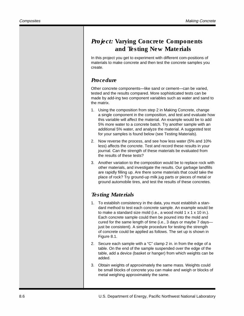
dard method to test each concrete sample. An example would beto make a standard size mold (i.e., a wood mold 1 x 1 x 10 in.).Each concrete sample could then be poured into the mold andcured for the same length of time (i.e., 3 days or maybe 7 days—just be consistent). A simple procedure for testing the strengthof concrete could be applied as follows. The set up is shown inFigure 8.1.
2. Secure each sample with a “C” clamp 2 in. in from the edge of atable. On the end of the sample suspended over the edge of thetable, add a device (basket or hanger) from which weights can beadded.
3. Obtain weights of approximately the same mass. Weights couldbe small blocks of concrete you can make and weigh or blocks ofmetal weighing approximately the same.

U.S. Department of Energy, Pacific Northwest National Laboratory 8.7
Figure 8.1. Testing Materials
Composites Making Concrete
4. Add weights one at a time to the basket until the sample breaks.
5. In your journal, record the weight necessary for failure to occur.

8.8 U.S. Department of Energy, Pacific Northwest National Laboratory
Composite ExperimentsInstructor Notes
ReliabilityAll these experiments work well. Some experiments may requireseveral trials if they have never been tried before.
Teacher Tips 1. These experiments help familiarize students with the processes
and materials used to make common composites.
2. The experiments demonstrate the relationship among materials,weight, design of structure, and cost by taking students throughbuilding and testing different materials, doing a simple and crudestrength-to-weight comparison, or a cost analysis of material types.
3. The experiments can also be highly detailed exercises in build-ing and testing several identically sized test samples exposed toidentical test conditions (See Young’s Modulus Testing of Beams).Students can observe vastly differing results because of differentmaterial characteristics, even though objects are built to the samedesign. To accurately test materials this way, it is important thatdimensions of each sample be identical.
4. Good examples exist of cross-linkage, types of fiber orientation,matrix formation, and stress/strain matrix curves in the Jacobs’textbook.
5. Epoxy curing time can be decreased by heating the epoxy in afurnace. Do not overheat the epoxy; it will burn. A suggestedtemperature of 50°C will dramatically decrease the curing time.
6. Fantastic household cleaner is an excellent substitute for cleaningsticky epoxy messes. We recommend this product (over acetone)because acetone has some health hazards associated with it.
7. Honeycomb is a difficult product to obtain. Boeing Surplus inSeattle, Washington, has been the main supply source. Contacta mentor teacher or PNL staff if additional material is needed.
8. Kevlar is made from fibers that are strong and thin. Specialceramic scissors from Jensen Tools, Inc. (See Vendor List inAppendix) are needed to effectively cut the fabric. These scis-sors are quite spendy. Use only as directed by manufacturer.
9. Tacky tape (zinc chromate) for the honeycomb composite project(#4) is supplied by Schnee-Morehead, Inc. (See Vendor List inAppendix). Some teachers have used molding clay with success.
Composites Composite Experiments

U.S. Department of Energy, Pacific Northwest National Laboratory 8.9
Suggestions for Conducting Introductionto Composite Experiments: Projects 1-4
The following four experiments are identical except that a material orprocess has been changed in each project.
As a manageable means to conduct the experiments and allow thestudents maximum exposure to a variety of composite materials with-out doing all the experiments, small work groups with separatecomposite activities may work best. A suggested way would be todivide the class into four groups. One group could hand laminatethe epoxy resin items while another group works with the epoxyresin items on the hydraulic press (see Table 8.1 for sample groupassignments).
When the groups complete the activity, each group reports their obser-vations, which have been written in their journals, to the entire class.Strength tests can then be conducted on the materials to further studyproperties of these composites.
Table 8.1. Sample Groupings for Composite Experiments
Group A1a Fiberglass cloth with epoxy resin hand laminated1b Fiberglass mat with epoxy resin hand laminated1c Fiberglass cloth with epoxy resin vacuum bagged1d Fiberglass mat with epoxy resin vacuum bagged1e Fiberglass cloth with epoxy resin hydraulic press1f Fiberglass mat with epoxy resin hydraulic press
Group B2b Kevlar with epoxy resin hand laminated2b Kevlar with epoxy resin vacuum bagged2c Kevlar with epoxy resin hydraulic press
Group C3a Honeycombed composite with hand laminated
glass cloth3b Honeycombed composite with vacuum bagged
glass cloth3c Honeycombed composite with hydraulic press
glass cloth
Group D4a Honeycombed composite with hand laminated
Kevlar cloth4b Honeycombed composite with vacuum bagged
Kevlar cloth4c Honeycombed composite with hydraulic press
Kevlar cloth
Composites Composite Experiments

8.10 U.S. Department of Energy, Pacific Northwest National Laboratory
Project 1: Fiberglass Hand LaminatingProcess
Student Learning ObjectivesAt the end of the activity students will be able to:
• make a composite to apply and test the concept of combining twoor more different materials to obtain a new material. The newmaterial will exhibit new and improved properties than the originalmaterials.
Materials• Fiberglass
• Epoxy resin (two-part kit)
• Paper measuring cup, 4-6 oz
• Brush (1 in.)
• Polyethylene, 8 x 36 in. (clear plastic bags)
• Acetone or Fantastic
• Tongue depressor or disposable stirring sticks
• Eye dropper
• Plastic gloves
• Wax paper or plastic for table cover
Procedure 1. Cut five to six 3- to 4-cm x 30- to 40-cm fiberglass strips (mats) with
scissors. Weigh the batch of strips to be used in the composite.
2. Approximately 2 oz of epoxy resin is needed for this experiment.Follow the directions on the back of the resin can, measuring theingredients into a paper cup. Thoroughly mix contents with tonguedepressor for 3-5 min.
3. Place polyethylene sheet on table top to protect the table.
4. Pour a small amount of resin onto the polyethylene surface.Note: resin does not stick to polyethylene. Spread to 4- x 40-cmarea with brush.
5. Place one fiberglass 3 to 4-cm x 30 to 40-cm mat onto the resin.
Composites Composite Experiments—Project 1

U.S. Department of Energy, Pacific Northwest National Laboratory 8.11
6. Dip brush into resin. Paint the resin into the fiberglass mat bygently stroking the brush over the fiberglass. Begin brushing inthe middle, and stroke toward the outer edges. The fiberglass willabsorb the previously poured resin. Apply only enough resin withthe brush to saturate the fiberglass.
7. Place second fiberglass mat (dull side up) onto the first layer.Apply resin with brush, working from the center out to prevent airbubbles. Add only enough resin with the brush to wet or saturatethe fiberglass.
8. Repeat process with each additional fiberglass laminate.
9. Upon completion, place brush into empty cup.
10. Cover the fiberglass laminate with a polyethylene sheet. Apply aflat weight (i.e., books, wood, or metal slab).
11. Observe the contents of the cup and brush to verify that the resinis curing. The cup will feel warm from an exothermic reaction thatis taking place. An odor will be increasingly noticeable as a chem-ical reaction occurs.
12. Clean the brush with acetone or Fantastic. Discard the cup andclean the table top if necessary.
13. Let the composite cure until rigid.
14. Take a final weight of the composite.
Extension Activities 1. Test the sample by breaking it. Determine the force necessary for
the composite to break.
2. Make additional samples of this same composite using moreepoxy. Be sure to weigh the fiberglass before and after makingthe sample. Test the sample as in 1 above. Record observationsand test results in your journal. Also be sure to record any differ-ences in processing the materials (i.e., change in size of fiber-glass mats, seepage of epoxy from mat, etc.). Does additionalepoxy strengthen the composite?
Composites Composite Experiments—Project 1

8.12 U.S. Department of Energy, Pacific Northwest National Laboratory
Project 2: Kevlar Hand Laminating Process
Materials• Kevlar
• Epoxy resin (two-part kit)
• Paper measuring cup, 4-6 oz
• Brush, 1 in.
• Ceramic blade scissors
• Polyethylene 8 x 36 in. (clear plastic bags)
• Acetone or Fantastic
• Tongue depressor or disposable stirring stick
• Eye dropper
• Plastic gloves
• Wax paper or plastic for table top cover
Procedure 1. Follow the same procedure used in Project 1, but use Kevlar
instead of fiberglass.
2. Kevlar is very difficult to cut with conventional scissors. Ask yourteacher for ceramic scissors to cut the Kevlar fabric.
Composites Composite Experiments—Project 2

U.S. Department of Energy, Pacific Northwest National Laboratory 8.13
Project 3: Press Laminating ProcessUsing Fiberglass
Materials• Fiberglass
• Epoxy resin (two-part kit)
• Hydraulic press with a minimum 3-in. x 12-in. pressure loadingsurface area
• Paper measuring cup, 4-6 oz
• Brush, 1 in.
• Polyethylene, 8 x 36 in. (clear plastic bags)
• Acetone or Fantastic
• Tongue depressor or disposable stir stick
• Eye dropper
• Plastic gloves
• Wax paper or plastic for table cover
Procedure 1. Prepare mats as in Project 1, using fiberglass and epoxy resin. Be
sure to weigh the batch of mats before applying the epoxy.
2. Cover the laminate (your composite matrix) with a polyethylenesheet. Place the laminate on a 3-in. x 12-in. metal plate and coverwith a matching metal plate.
3. Place the plates in the hydraulic press and apply enough pressureto force the excess resin from the composite. It would be wise tohave a catch basin of aluminum foil or plastic to catch any resinthat might run over the edge of the pressure plates as the resin isextruded by the pressure.
4. Let the composite cure.
5. Clean the brush with acetone or Fantastic. Discard the cup andclean the table top if necessary.
6. Trim excess resin from the edges of the composite.
7. Weigh the composite after it has been peeled from the polyethyl-ene cover.
8. A comparison can be made at this point of the amount of resin ittakes to make a hand-laminated composite versus a pressure-compressed composite.
Composites Composite Experiments—Project 3

8.14 U.S. Department of Energy, Pacific Northwest National Laboratory
Project 4: Honeycomb Composite UsingVacuum Bag Process
Student Learning ObjectivesAt the end of the activity students will be able to:
• construct, apply a vacuum, and observe curing a hand lay-uphoneycomb core composite.
Materials• 3-5 mil polyethylene sheet (20 x 20 in.)
• Zinc chromate tape (tacky tape) or clay
• Honeycomb
• Fiberglass cloth
• Epoxy resin (two-part kit)
• Osnamburg-bleeder cloth (throw-away fabric to absorb excess resin)
• Paper cup
• Stir stick
• Paint brush, 1 in. wide
• Perforated Teflon or perforated polyethylene
• Silicone mold release
Equipment• Aluminum vacuum plate
• Vacuum pump
Note 1. Use a minimum of the epoxy resin on the fiberglass as the resin
will bleed out as a vacuum is applied.
2. Cover vacuum hole in aluminum plate with a gauze pad or foldedbleeder cloth to prevent resin from plugging vacuum pump/line.
Procedure 1. Apply silicone mold release to an aluminum plate (see Figure 8.2).
Rub or spray on silicone, and gently wipe off excess. Silicone pre-vents the composite from sticking to the plate.
2. Cut polyethylene sheet at least 2 in. larger than the honeycombpiece to be made or processed.
Composites Composite Experiments—Project 4

U.S. Department of Energy, Pacific Northwest National Laboratory 8.15
Composites Composite Experiments—Project 4
Figure 8.2. Aluminum Vacuum Plate Used in Vacuum Bag Process
ThreadedFitting
1/4 in. diam.coppertubing Aluminum Plate
18 in.
18 in.
1/4 in.thickness
18 in.
18 in.
1/4 in. diam.coppertubing Aluminum Plate
ThreadedFitting
1/4 in. thickness
3. Cut four pieces of fiberglass 1 in. larger than the honeycomb piece.
4. Mix resin and catalyst at appropriate ratio, as instructions direct.
5. Place fiberglass cloth onto polyethylene sheet, and carefully workresin into cloth with a 1-in. brush, from the center to outer edges.
6. Repeat for second layer of fiberglass, working resin in with brush.
7. Place honeycomb onto fiberglass.
8. Place next layer of fiberglass cloth on top of the honeycomb.
9. Repeat steps 5 and 6, working resin into fiberglass.
10. Lay perforated plastic or Teflon on top of final fiberglass layer.
11. Place bleeder cloth over the composite laminate.
12. Apply zinc chromate tape (tacky tape) around outer edge ofaluminum vacuum plate. This creates an air-tight barrier.
13. Cover with polyethylene sheet being careful that a seal is formedas the polyethylene contacts the tacky tape.
14. Pull a vacuum of 20 in. of mercury on the vacuum plate untillaminate has cured.
15. Shut off the vacuum, and unwrap composite from vacuum appara-tus. You now have a honeycomb composite material.
16. Discard materials that cannot be reused.
17. Check for defects where epoxy did not laminate the honeycomband fiberglass skin. It may take several tries to obtain a well-laminated composite.

8.16 U.S. Department of Energy, Pacific Northwest National Laboratory
Simple Stessed-Skin CompositeInstructor Notes
ReliabilityThese demonstrations work well.
Teacher Tips 1. The experiment outlined is designed for minimal expense per con-
cept learned. If students are interested in exploring the capabilitiesof different reinforcement fibers, such materials as Fiberglasscloth, woven Kevlar, or woven graphite fibers can all be used tomake additional beams that can be evaluated by the cantileverbeam test (see Young’s Modulus Testing of Beams). Additionally,other fabrication techniques such as vacuum bagging may beused to achieve better bonding while using even less epoxy. Tosave on supplies and time, the instructor may wish to preparedemonstration beams using the more exotic materials rather thanhaving each student make all the beams. These demo beamsmay then be measured nondestructively for stiffness using thecantilever beam apparatus.
Prerequisite: The student should understand the concept ofYoung’s modulus of elasticity, a measure of a material’s stiffness.The Jacob’s textbook is a reference for this information.
DemonstrationThe following two demonstrations are a lead-in to the next activity.
ProcedureDemonstration 1:
1. With a dark ink marker, draw on one face of a foam-rubber beamevenly spaced (i.e., 1 cm) lines (Figure 8.3).
2. Demonstrate by bending the foam rubber beam that the initiallyparallel lines get farther apart on one side (the tensile side) andcloser together on the other side (the compressive side, seeFigure 1).
3. Introduce the concept of stressed-skin composites by stating thata strong and stiff material, if attached to these faces, will providesubstantial reinforcement to the structure by resisting such tensileor compressive forces.
Composites Simple Stressed-Skin Composite

U.S. Department of Energy, Pacific Northwest National Laboratory 8.17
Composites Simple Stressed-Skin Composite
Before Bending
Tension
Compression
Bent
Figure 8.3. Foam-Rubber Beam Used to Illustrate Tensile and Compressive Forces Resulting From Bending
Demonstration 2:
Bend precut pieces of polyurethane foam insulation (8 cm x 8 cm x30-40 cm) with vertical lines 1-cm apart on all 8-cm faces. Studentswill soon note that the beam is not very stiff and will not bend veryfar before breaking.

8.18 U.S. Department of Energy, Pacific Northwest National Laboratory
Composites Simple Stressed-Skin Composites Using Paper Reinforcement
Activity: Simple Stressed-Skin CompositesUsing Paper Reinforcement
Student Learning ObjectivesAt the end of the activity students will be able to:
• demonstrate the composite reinforcement concept using readilyavailable materials
• demonstrate the consequences of certain defects in these structures.
• quantify the gains made by engineered composite construction,using a simple measurement of Young’s modulus of elasticity.
Materials• Foam rubber beam about 8 cm x 8 cm x 30 cm, with vertical lines
on all of the 8-cm faces
• Polystyrene or polyurethane insulating foam, cut into 3 x 3 x 18 cmstrips
• Heavy paper such as construction paper
• Waxed paper or polyethylene
• Slow-setting (>3 h) non-allergenic epoxy resin, curable at roomtemperature
Equipment• Cantilever beam-loading device (See Young’s Modulus Testing of
Beams in this section)
• Known weights of about 100 g
• Dial-gauge indicator capable of measuring to 0.025 mm (althoughmost will measure in thousandths of an inch)
• Calculator
Procedure 1. Prepare stressed-skin composites as follows: leave one beam as
is; bond one 3 x 18 cm face of a second beam with constructionpaper; bond both 3 x 18 cm faces of a third beam with construc-tion paper; make the fourth beam the same as the third, but makean intentional disbond by placing a piece of waxed paper orpolyethylene 3 cm x 6 cm at the midpoint of one of its paper-reinforced faces. To achieve the best possible bond, use minimalepoxy, but be certain of complete coverage. Weight the beams

U.S. Department of Energy, Pacific Northwest National Laboratory 8.19
Figure 8.4. Two-Faced ReinforcedBeam
with books, wood, or bricks to push materials together or tocompress them during the curing process. Use waxed paper orpolyethylene to separate the composites from surfaces such astabletops where bonding is not desired.
2. To test the beams, weigh them after any necessary trimming,then record the weight gains (relative to a nonreinforced beam)for reference. Bend the non-reinforced beams again for calibra-tion purposes. Then bend the single-sided beam with the non-reinforced face first on the tensile side; the beam should be bentonly slightly, taking care not to break it. Note that this one-sidedreinforcement does not have much effect on the stiffness. Finally,bend the beam, so that the nonreinforced face is on the compres-sive side until it breaks. Note that the foam collapses on thecompressive side. This is because the reinforcement has madethe beam much stronger on the tensile side.
3. Now bend the two-faced reinforced beam without the intentionaldebond; it is noticably stiffer than either of the two precedingbeams (See Figure 8.4). You may want to break some of thesebeams to observe whether failure occurs on the tensile or com-pressive face. Next, bend the defected beam, but not to thebreaking point, with the defect on the tensile side. Note that thedefect has essentially no effect. Finally, bend the defected beamwith the defect on the compressive side until it fails. Note that thenonbonded paper pops away from the foam in what is known asbuckling. Buckling is a fairly common failure mode for this kind ofcomposite and can be avoided by close attention to completeepoxy coverage as the composite is being constructed.
4. See Young’s Modulus Testing of Beams activity in this section.
5. Follow the same procedure with the one-sided and two-sidedreinforced beams. The deflection should be at least 0.25 mm; ifnot, apply more weight until it is. You will note that the beamreinforced on one side is not much stiffer than the one withoutreinforcement, just as was learned by hand bending. Similarly,the two-sided reinforcement produces impressive gains in stiff-ness. Some students may want to relate the stiffness gains to theweight gains involved in the various reinforcements. Although thestiffness of the foam beams has been increased greatly by usingonly paper reinforcement, the resulting composites are not verystiff when compared with other materials. However, the densityof the foam beams is very low compared with other solid materi-als. The following values of Young’s modulus for some commonmaterials may be useful for comparison:
Material E, GPaAluminum 69Steel 207Many solid polymers 3Glass 69Note: 1 GPa = 109 Pa.
Composites Simple Stressed-Skin Composites Using Paper Reinforcement
Polystyrene Tension Paper
Compression

8.20 U.S. Department of Energy, Pacific Northwest National Laboratory
Activity: Young’s Modulus Testingof Beams
Student Learning ObjectivesAt the end of the activity students will be able to:
• set up a sample beam of material for testing
• test the sample beam or material
• calculate Young’s Modulus.
Materials• Prepared sample or beam
Equipment• Apparatus for testing Young’s Modulus (Figure 8.5)
• Dial indicator
• Support for dial indicator
• Weights
• Calculator
Procedure 1. Clamp material (test specimen or sample) to be tested to the
upright 2 x 4 in. wood beam.
2. Adjust the dial indicator so it just touches the bottom of thespecimen or sample.
3. Zero the dial indicator.
4. Place 50-g weight into paper cup placed on top of the specimen(see Figure 8.5).
5. Record deflection of dial indicator.
6. Continue adding weights if desired to get measurable deflection.
7. Calculate Young’s Modulus using the following equation:
Young’s Modulus (in Pascals, Pa) = 4(98) WL3/DBH3
where W = weight in g; L = unsupported length of sample in cm;D = deflection of unsupported sample in cm; B = width of samplein cm; H = height of sample in cm; and 98 = conversion factor tochange g/cm2 to Pascals, the international unit for elastic modulus.
Composites Young’s Modulus Testing of Beams

U.S. Department of Energy, Pacific Northwest National Laboratory 8.21
Paper Cup
Figure 8.5. Apparatus Used to Evaluate Stiffness of Composite Beams byMeasuring Deflection of a Cantilever Beam in Bending
Clamp
2 x 4(wood)
Base (Wood)
Composites Young’s Modulus Testing of Beams
Specimen
DialIndicator
Steel Base
H
D

8.22 U.S. Department of Energy, Pacific Northwest National Laboratory
AirfoilsInstructor Notes
ReliabilityThis experiment will work well. The airfoils produced will have measur-able lift and give measurable differences in weight to strength ratiosfor the various airfoil designs.
Teacher Tips 1. Balsa sheets are available from hobby supply stores and some
scientific supply catalogs. Total cost for this activity is approxi-mately $200.00 for a class of 25 students.
2. Transparent polyester (monokote) is available from model air-plane hobby shops.
3. The glue to bond the balsa is cyanoacrylate (Superglue). Commonbrands used in model airplane building are Zap and Hot Stuff.
Caution: Avoid breathing the fumes of reacting cyanoacrylate.Be careful not to bond fingers together as cyanoacrylate adheresquickly and tenaciously to skin. If this should happen, use thedebonding chemical available at hobby shops, or wait 10 minbefore slowly rolling the bonded surfaces apart. Do not pull fingersdirectly apart or use sharp blades to cut the skin surfaces apart.Take extra care to avoid getting glue in your eyes.
4. The special iron designed for use in model construction and thehigh-temperature heat gun used in model construction are avail-able from hobby stores.
5. The various parts of the wing are illustrated and labeled for orien-tation in Figure 8.6. Figure 8.7 gives the actual size for the airfoilused in the project. If you wish to do a larger or smaller version ofthe airfoil, it can be enlarged or reduced on a photocopier.
6. In testing the airfoil, the free-end length needs to be carefully meas-ured as load deflection is a cube function. Figure 8.8 shows apossible test system.
7. When students are testing airfoils for failure, it is wise to check theapproximate distance they have placed their weighing containerfrom the floor: If the container is placed more than 5 cm from thesupporting surface, the airfoil will be totally destroyed when it fails.
Composites Airfoils

U.S. Department of Energy, Pacific Northwest National Laboratory 8.23
8. In discussing cause(s) for failure, students should speculate onwhat could have been done differently during construction. All thewings tested so far have failed at the point of attachment to theclamp and the test apparatus. Failure occurs under compressionat the interface between the wing and the clamp.
9. Students could now build a second modified wing that remediesthe problem, or they could build an identical wing with differentmaterials (say a wing made from polystyrene insulating foam cov-ered with balsa—which makes impressive gains in mechanicalstrength). They should stay within the weight limits; keep weightto a minimum.
10. Keep these results to build a data base as other classes conductthis project.
Composites Airfoils

8.24 U.S. Department of Energy, Pacific Northwest National Laboratory
Project: Constructing and Testing aComposite Airfoil
Student Learning ObjectivesAt the end of the activity students will be able to:
• test a constructed airfoil to determine its relative stiffness and pointof destruction
• graph results of different designs to determine the best construction.
Materials• Balsa wood, sheet 1/16 in. x 3 in. x 36 in. (36)
• Balsa wood leading edge 3/8 in. x 5/16 in. x 36 in. (18)
• Balsa trailing edge 1/8 in. x 3/4 in. x 36 in. (16)
• Balsa 1/8 in. x 1/4 in. x 36 in. (12)
• Spruce 1/8 in. x 1/4 in. x 36 in. (9)
• Bicarbonate of soda, Na2HCO
3 (baking soda)
• Transparent polyester covering material, Monokote or equivalent(2 sq yd)
• Glue, cyanoacrylate (Zap or Hot Stuff)
• Wax paper
• Sand paper, 150 grit
• Strong string or duct tape
Equipment• T head pins (1 box)
• Heat gun (high temperature) used in model construction
• Electric iron, designed for model construction
• Plastic or cloth bag (or plastic pail)
• Meter stick
• Steel templates, cut to Clark Y airfoil shape, with notches for spars
• X-Acto knives or equivalent hobby knives with straight point blades
• 60 x 120 cm fibrous ceiling tile, flat finish (building board)
• Trays (6), approximately 5 x 15 cm long for sodium carbonate
• Vacuum cleaner with brush
Composites Airfoils

U.S. Department of Energy, Pacific Northwest National Laboratory 8.25
Procedure 1. Use Table 8.2 to select the balsa and/or spruce your group will
use to construct the airfoil. Cut the pieces slightly larger than thetemplates from the 1.6 mm (1/16 in.) sheets of balsa. Drill holes inthe balsa to accommodate the posts of the template.
Table 8.2.
Variation Description
BW Ribs 6 cm apart, balsa spars
BN Ribs 3 cm apart, balsa spars
BWS Ribs 6 cm apart, balsa spars, shear webs
SW Ribs 6 cm apart, spruce spars
SN Ribs 3 cm apart, spruce spars
SWS Ribs 6 cm apart, spruce spars, shear webs
BW = balsa with wide spars; BN = balsa with narrow spars; BWS = balsa withshear webs; SW = spruce with wide spars; SN = spruce with narrow spars;SWS = spruce with shear webs
2. Make a template-balsa sandwich using all rib pieces.
3. Carve and sand the balsa to match the templates; be careful notto sand the templates themselves.
4. To make notches for the spars, (see Figures 8.6 and 8.7) glue a10-cm strip of 150-grit sandpaper to the 1/4 in. face of some scrapspruce spar wood. Sand the spar notches in the ribs, avoidingenlarging the notches in the templates.
5. Take a piece of wax paper large enough to cover the buildingboard, and mark reference lines on it to guide the placement ofthe spar and ribs. Be sure the reference lines are spaced correctlyfor your airfoil ribs and are at right angles to the spar reference line.
6. Cover the building board with the wax paper. This will prevent thewing from becoming glued to the board as well as giving you aplacement guide for the spar and ribs.
7. Pin the bottom spar in place on the building board.
8. Pour sodium bicarbonate (Na2HCO3) into a long narrow tray.
9. Dip the rib pieces into the sodium bicarbonate. The tiny amountof soda that sticks to the rib will accelerate the reaction of thecyanoacrylate and strengthen the bond.
10. Hold each rib perpendicular to the building board, making sureeach closely follows the reference lines.
Composites Airfoils

8.26 U.S. Department of Energy, Pacific Northwest National Laboratory
Composites Airfoils
Figure 8.6. Construction Details of a Model Airplane Wing
Figure 8.7. Clark Y Airfoil (pattern for template—enlarge as necessary)
11. Apply the cyanoacrylate to the junction of the spar and rib. Thebond will secure this junction in 2 to 3 seconds.
Caution: Avoid breathing the fumes of reacting cyanoacrylate.Be careful not to bond fingers together as cyanoacrylate adheresquickly and tenaciously to skin. If this should happen, use thedebonding chemical available at hobby shops, or wait 10 minbefore slowly rolling the bonded surfaces apart. Do not pull fingersdirectly apart or use sharp blades to cut the skin surfaces apart.Take extra care to avoid getting glue into eyes.

U.S. Department of Energy, Pacific Northwest National Laboratory 8.27
12. Set the top spar securely in place, and apply cyanoacrylate to thejoints.
13. Pin leading edge and trailing edge in place. Under the leadingedge, use a 3-mm (1/8-in.) shim to hold it up, since the airfoil isnot quite flat.
14. Bond with cyanoacrylate.
15. If shear webs are to be attached to the spars, cut the webs so thegrain of the wood is perpendicular to the building board, then bondto the front and back surfaces of the top spar with cyanoacrylate.
16. Remove the wing, turn it over, and then bond the bottom spar andshear webs together with cyanoacrylate.
17. The outer ribs on each end of the wing need to be strengthenedto prevent warpage as the wing-covering material shrinks. Tostrengthen each end rib, glue a piece of scrap spar material ontothe outer ribs.
18. Carefully sand the wing as necessary. Use a vacuum cleaner withbrush to remove dust. Set aside wing while you prepare the trans-parent polyester covering material.
19. Cut a piece of covering approximately 1 cm larger on all sidesthan the wing. Follow manufacture’s instructions for applying thecover-ing, first tacking it in place using an iron, then use a heatgun to shrink the film.
Testing 1. Record the weight of each wing to be tested for strength and
stiffness.
2. Using a clamp that fits the shape of the airfoil’s top profile, fastenthe wing to the edge of the workbench, allowing approximately35 cm of the airfoil to hang free like a cantilever (see Figure 8.8).Because the deflection under load is a cube function, the freelength should be carefully controlled.
3. Suspend a container (plastic or cloth bag or small plastic pail) fromthe top spar using a strong string or duct tape. Weight will be addedto the container that will cause deflection. This container shouldbe about 5 cm from the floor. Can you think of a reason why?
4. Using a meter stick fixed to the base, measure the distance tothe nearest millimeter from the lower wing surface to the floor.
5. Place weights in the suspended container until a defection of1 cm is attained.
6. Weigh the container and weights, and record the value in yourjournal.
Composites Airfoils

8.28 U.S. Department of Energy, Pacific Northwest National Laboratory
Composites Airfoils
Figure 8.8. Arrangements to Test Stiffness and Strength of Airfoil Sections
7. Continue adding weight until failure occurs. Record the failureweight and the approximate deflection at failure in your journal.
8. Observe and describe the failure point and any characteristicsthat you saw during the loading process in your journal.
9. Plot class test results with the x-axis as the structure type andthe y-axis as the weight to cause the 1 cm deflection (graph I)and the weight to cause failure (graph II).
10. Observe the graphs for any pattern or trends. Are the two graphssimilar?

U.S. Department of Energy, Pacific Northwest National Laboratory 8.29
Making PaperInstructor Notes
ReliabilityThis lab works very well with any plant material. However, it is notrecommended that students use wood as it takes too long and can behard on the blender. Leaves, straw, rice, and grasses work well. Youmay want to experiment and use cardboard, used paper, constructionpaper, or blue jeans in making paper.
Teacher Tips 1. Using the borates for pulping is much safer than using sodium
hydroxide. All work well however. Care should be taken whenheating so the solution does not boil over. The solution is hotand caustic. If students get splashed, rinse off immediately.
2. Screen door screen works well for the deckle (screen). Do notuse fiberglass screen as it is too flexible.
3. The size of the screen is not important. Use a size that will fit inthe tray you will use to hold the pulp mixture.
4. Often the pulp sticks to screen a little, a gentle pry at a cornerwill release the pulp from the screen.
5. When ironing the paper, turn the cloth over to speed drying. Thecloth will come off easier if the paper is not dried to a crisp.
6. Stopping at any point where indicated will not change the endresults. This lab can be done over several weeks, if the need arises.
7. For students who want to go farther, they can add potassium alumto make the paper waterproof or add a piece of thin wire or threadto the screen before pressing to make water-marked paper.
8. To get a whiter paper, the pulp can be bleached with ordinaryhousehold bleach. Simply add about 50 mL of bleach to themixture after boiling and before blending. Allow to set overnight.Rinse bleach out the next day, and then continue with the pulpingoperation.
9. Paper is made from cellulose fibers. Although many differenttypes of plants are used to produce paper in the United States,most paper is made from trees.
10. The Egyptians used papyrus to create the first paper-like writingsurface. Paper as we know it today was probably invented inChina. Papermaking was for centuries a slow and difficult pro-cess. In the early 1800s, the continuous roll method of makingpaper was developed so paper could be mass produced.
Composites Making Paper

8.30 U.S. Department of Energy, Pacific Northwest National Laboratory
11. Recycled paper is now being used to create “new” paper. Wastepaper is dumped into a large mixing machine called a pulper pit.Here the paper is mixed with water, heated, and becomes “pulp.”The pulp is forced through screens of smaller and smaller meshto remove foreign objects. To remove the ink the pulp goesthrough several tanks where it is bleached to form a white pulp.Paper that is not “de-inked” is considered “minimum impactpaper”. The bleached, cleaned pulp is spread on large rolls ofscreen and is pressed and dried to form paper.
12. References: Burdette, Conway and Ernst. 1988. The Manufactureof Pulp and Paper: Science and Engineering Concepts, TappiPress; American Paper Institute. 1972. The Statistics of Paper,New York.
Composites Making Paper

U.S. Department of Energy, Pacific Northwest National Laboratory 8.31
Project: Making Paper
Student Learning ObjectivesAt the end of the activity students will understand how to:
• make a cellulose pulp from plant material
• make paper from pulp.
MaterialsFor making pulp:
• Dried plant material
• Cheese cloth
• String
• Pulping chemical (borax or sodium borate, sodium pyroborate,sodium tetraborate, or sodium hydroxide)
• Red litmus
For making paper:
• Pulp
• Wire screen (screen door screen 10 cm x 10 cm or to fit tray)
• Masking tape or plastic tape
• Plastic tray (for wire screen to fit into)
• Cookie sheet
• Sponges
• Pieces of cloth (cotton is best)
• Blocks of wood to fit wire screen
• Micropipette
• Spatula
• Stirring rod
• Electric iron - to be shared
• Chemical goggles
Composites Making Paper

8.32 U.S. Department of Energy, Pacific Northwest National Laboratory
AAAAAA
Cold Water
LitmusPaper
Cheesecloth Bag
Cheesecloth
Equipment• Balance
• Scissors
• Hot plate or other source of heat
• 600 mL beaker or suitable container
• Blender
Procedure 1. Preparing the plant material: Cut two pieces of cheesecloth into
25-cm x 25-cm squares. Lay one piece of cheesecloth on the other.Cut the dried plant material into the center of the cheesecloth.Make the pieces less than 1 cm in length. Gather the cheeseclothto make a large “tea bag” with the cut plant material inside. Writeyour name on a tag and attach to a string to identify your tea bag.
(You may stop at this point if time runs out)
2. Boiling: Place your tea bag in the 600-mL beaker. Add enough warmwater in 100-mL increments to cover your “tea bag.” Add 10 g ofpulping chemical for each 100 mL of water you used. (Note if youare using sodium hydroxide use 5 g for each 100 mL of water used.)Place the beaker on the hot plate. Adjust heat to gently boil thecontents for 45 min to 1 hour. Add hot water as the water in thebeaker boils away. If time allows, boiling can continue for severalhours. (Note: Boiling plant material in pulping chemical creates asmell some people find unpleasant. Do this activity in a well-ventilated area.)
Caution: Use chemical goggles.
(You may stop at this point if time runs out. Just leave the tea bagin the beaker with the pulping chemical. Turn off the heat!)
3. Washing: Carry the beaker carefully to a sink. Turn on the coldwater, and empty the beaker into the sink. Note the color of theliquid. Fill the beaker with cold water and dip your “tea bag” in andout of the water several times. Empty the pot. Refill the beakerwith water and repeat dipping process. Continue to wash your “teabag” in this manner until the water rinse is uncolored. Test a fewdrops of this water with red litmus paper. Wash your “tea bag”until the rinse water will not turn red litmus blue. When the litmusstays red you have removed all the pulping chemical.
(You can stop at this point. You can store your rinsed tea bag in atightly sealed container at room temperature for a day or two.Refrigerate if storage is for a longer period.)
Composites Making Paper
Cheesecloth Bag
Cheesecloth
LitmusPaper

U.S. Department of Energy, Pacific Northwest National Laboratory 8.33
AAAAAAAAAAAAAAAAAAAAAAAAAAAA
ScreenWith PulpOn Top
AAAAAAAAAAAAAAA
AAAAAA
Sponge
Cookie Sheet
Felt
Wood
AAAAAAAAAAAAAAAAAAAAAAAAAAAAAAAAAAAA
Screen With PulpOn Top
AAAAAAAAAAAAAAA
AAAAAAAA
Sponge
Cookie Sheet
AAAAAAAAAAAAAAA
Screen
Cake Pan
Pulp Mixture
4. Pulping: Squeeze your “tea bag” to press out most of the water.Cut open the bag. Put a handful of your plant material into a foodblender (save the rest in a covered container). Add 20 to 30 mL ofwater, and place the cover on the blender. Turn on the blender forabout 10 sec. If the blender does not mix the material smoothly,turn it off. Add another 20 mL of water and try again. Continueadding water until the mixture blends smoothly. Blend for 1 min atmedium speed. Stop the blender and look carefully at the pulp.Blend for another minute and look at the pulp again. Continueuntil the pulp stops changing in appearance. You now have pulpto make paper. Pour your pulp into a storage container; put a lidon it.
(You may stop here. Pulp can be stored at room temperature fora day or two or in the refrigerator for several weeks.)
5. Making paper:
A. Making a screen
There are several ways to add an edge to the screen. Theseedges make it easier to remove the paper from the screen later.Your screen can be used over and over again. The easiest way isto place masking tape all the way around the four edges of yourscreen.
B. Loading the screen
Soak the sponge and the pieces of cloth in water. Squeeze out asmuch water as you can, then place the sponge on the cookie sheet.Just before you begin, plug in the iron and turn it on medium heat.Pour 1 to 2 cm of water into the plastic tray. Add some of yourpulp to the water. Stir the mixture well to separate the fibers of thepulp. Add pulp until the mixture is a little too thick to see through.Slide the wire screen into the pulp mixture from one end, and let itrest on the bottom. Do not drop the screen in the mixture as it willtrap the fiber below the screen. Move the screen around and stirup the mixture to get an even layer of pulp above the screen. Liftthe screen out of the pan, and place it on the damp sponge. Thepulp side should be up. Use your finger to push any tufts of pulpthat hang over the border of the screen onto the open meshwork.This will make it easier to pull the paper off the screen later. Checkthe pulp visually for bare spots. Use a micropipette to add a fewdrops of undiluted pulp to fill in any bare spots.
C. Pressing the pulp
Place a piece of damp cloth over the pulp on the screen. Place ablock of wood over the cloth. Press down on the wood as hard asyou can to squeeze most of the water out of the pulp. Lift off theblock of wood, and set it aside. Lift the sandwich of cloth, pulp,and screen off the sponge. Turn the sandwich over so the screenis on top. Lift one corner of the screen so you can see the pulp.Use a thin spatula (or the blade of a knife) to peel the sheet of
Composites Making Paper
Screen
Sponge
Cookie Sheet
Cake Pan
Pulp Mixture
Screen with Pulpon Top
Cookie Sheet
SpongeFelt
Wood
Screenwith Pulpon Top

8.34 U.S. Department of Energy, Pacific Northwest National Laboratory
Cloth
Cloth
Paper
Pulp
Cloth
Cloth
Wood
Cloth
Cloth
Pulp
Wood
pulp off the screen. Work slowly and carefully. Don’t worry if youtear the sheet of pulp. To repair tears, use a micropipette to puta few drops of pulp mixture over any tears.
D. Drying the paper
Cover the sheet of pulp with another sheet of damp cloth. Iron thissandwich (cloth, pulp, cloth) until it is completely dry. You mayturn the sandwich over once or twice as you are ironing to speeddrying. When the sandwich is completely dry, carefully peel thetwo pieces of cloth away from the paper. Examine the paper thatyou have made.
(You can make as many sheets of paper as time permits now.Just remember to add undiluted pulp as you remove more sheetsof pulp.)
Extension Activities 1. Compare different types of paper (look at fibers under a micro-
scope).
2. Research the current technology being used to recycle paper andproduce “new” paper.
3. What is dioxin? Why is/could it be a problem? How is it used inpapermaking?
4. What do wasps have to do with the topic of paper?
5. What is a watermark? Create your own paper that has your ownwatermark.
6. Investigate the history of rice paper.
7. Create masks using paper.
8. Use various materials to create paper, or add flowers or fabric toyour pressed pulp to make designs.
Composites Making Paper
Cloth
Paper
Cloth
Cloth
Cloth
Pulp
Wood
ClothPulpClothWood

U.S. Department of Energy, Pacific Northwest National Laboratory 8.35
Peanut BrittleInstructor Notes
ReliabilityThis activity works well if directions are followed, but success will vary.It is an excellent activity before winter break.
Estimated Time for ActivityOne class period.
Teacher Tips 1. This lab’s origin is unknown, but it is a well-known and much
appreciated (delicious) experience.
2. It is important that you protect the students and yourself fromharmful chemicals by
• making sure the equipment is clean (beakers, thermometer,stirring rod). Purchase and dedicate the equipment for onlythis lab. You don’t want contamination. Washing and sterilizingequipment at the end of the lab and storing it for next year willhelp ensure cleanliness.
• making sure the materials are new and fresh
sucrose is table sugarglucose is corn syrupmixed esters are margarineprotein pellets are peanutssodium bicarbonate is baking soda4-hydroxy-3-methoxybenzaldehyde is vanilla (artificial OK, real is better)
3. Students may over heat the sugar solution and burn it (Yuk!).
4. When adding vanilla and baking soda, the beaker should be heldwith a hot pad.
5. It is recommended that raw spanish peanuts be used, but this isdefinitely not necessary. They cook as the brittle is formed.
Safety 1. Be careful of flames and hot surfaces, burns are possible.
2. If glass rods or thermometers break, discard the batch.
3. Do not use mercury thermometers.
Composites Peanut Brittle

8.36 U.S. Department of Energy, Pacific Northwest National Laboratory
Activity: Peanut Brittle
Student Learning ObjectivesAt the end of the activity students will be able to:
• investigate the formation of a delicious composite material by theinfusion of CO
2 into a mixture of protein inclusions and foamed
saccarides
• Cooperate with other students in performing this activity in a smallgroup because of time limitation
• understand this experiment is edible, cleanliness is absolutelynecessary.
Materials• Sucrose, 75 g
• Glucose, 3M, 60 g
• Water, 20 mL
• Mixed esters, 19 g
• Protein pellets, Spanish, 50 g
• Sodium bicarbonate, 4 g
• 4-hydroxy-3-methoxybenzaldehyde, 1.0 mL
• Paper towels, 30 cm x 30 cm
• Plastic cup (5), 3 oz.
• Aluminum foil, 30 cm x 30 cm
Equipment• Safety glasses
• Beaker, 400 mL
• Beaker tongs
• Stirring rod
• Bunsen burner/hot plate
• Ring stand and ring
• Wire gauze (ceramic centered)
• Graduated cylinder, 25 mL
• Thermometer (candy)
• Scale/balance
Composites Peanut Brittle

U.S. Department of Energy, Pacific Northwest National Laboratory 8.37
Procedure 1. Clean laboratory. Wipe down balance/scale and areas surround-
ing it with a damp cloth. Wash any other surfaces that will be usefor this experiment. Wash your hands too!
2. Keep an accurate record of the process you followed in yourlaboratory journal.
3. Weigh out 75 g of sucrose into a plastic cup.
4. Weigh out 60 g of 3M glucose solution into a plastic cup.
5. Measure out 20 mL of water into a plastic cup, using graduatedcylinder.
6. To a 400-mL beaker add steps 1-3.
7. Heat this mixture of saccarides slowly. Stir constantly. Bring to aboil. Use as cool a flame or heat that will maintain boiling. Avoidburning the saccarides.
Note: Never stir solution with your thermometer; always use astirring rod.
8. Weigh out 7 g of solidified mixed esters in a plastic cup. Add 6 gof the solidified mixed esters to the boiling glucose-sucrose solu-tion. Take the remaining 1 g of solidified mixed esters, and lightlycoat a 30-cm square of aluminum foil.
9. Continue to heat and stir. Use beaker tongs to stabilize the beakerwhile stirring.
10. Weigh out 50 g of Spanish protein pellets on a piece of 30-cm-square paper towel.
11. When the temperature reaches 138°C, add the Spanish proteinpellets (containing arachin, conarchin, and oleic-linoleic glycerides.)
12. Continue to stir.
13. Weigh out 4 g of NaHCO3 into a plastic cup.
14. In a 25 mL graduated cylinder, put 1.0 mL of 4-hydroxy-3-methoxybenzaldehyde.
15. Prepare a pad by folding a paper towel into fourths.
16. When the temperature reaches 154°C, remove the beaker fromthe heat source. Place the beaker on the paper pad near thealuminum foil. Remove the thermometer.
17. While one partner holds the beaker and is prepared to stir, theother adds the 4-hydroxy-3-methoxybenzaldehyde and NaHCO
3.
18. Stir vigorously. When the rising mixture slows, pour the mixtureon to the aluminum foil.
Composites Peanut Brittle

8.38 U.S. Department of Energy, Pacific Northwest National Laboratory
19. When the mixture has cooled, break up the new product, submita small sample for judging, and consume the rest at will.
20. Thoroughly clean all equipment and the laboratory; remember,this experiment is edible, so make sure to clean all equipmentso the next group can use it. Dispose of paper towel and plasticcups.
21. Finish writing observations in your journal. Write a summary reportof this lab to include generic terms for ingredients and the productyou made.
Composites Peanut Brittle

U.S. Department of Energy, Pacific Northwest National Laboratory 8.39
Vocabulary—Composites*
Advanced composites
Cermets
Composites
Curing
E-glass
Fatigue
Fiber
Filament
Carbon black
Epoxy
Laminated composites
Sandwich composites
Glass fibers
Kevlar
Laminate
Matrix
Nondestructive evaluation
Pre Preg
S-glass
Whisker
Specific stiffness
Composites Vocabulary
*Instructor may vary vocabulary to suit particular content presented.

8.40 U.S. Department of Energy, Pacific Northwest National Laboratory