cement and concrete composites - columbia university
TRANSCRIPT

lable at ScienceDirect
Cement and Concrete Composites 77 (2017) 49e59
Contents lists avai
Cement and Concrete Composites
journal homepage: www.elsevier .com/locate/cemconcomp
Experiments and micromechanical modeling of electrical conductivityof carbon nanotube/cement composites with moisture
Sung-Hwan Jang a, b, Daniel Peter Hochstein a, c, Shiho Kawashima a, Huiming Yin a, *
a Department of Civil Engineering and Engineering Mechanics, Columbia University, 610 Seeley W. Mudd 500 West 120th Street, New York, NY 10027, USAb Robotics Institute, School of Computer Science, Carnegie Mellon University, Pittsburgh, PA 15213, USAc Department of Civil and Environmental Engineering, Manhattan College, 4513 Manhattan College Parkway, Riverdale, NY 10471, USA
a r t i c l e i n f o
Article history:Received 7 November 2015Received in revised form20 September 2016Accepted 7 December 2016Available online 19 December 2016
Keywords:Electrical conductivityCement pasteMulti-walled carbon nanotubesMoistureMicromechanical model
* Corresponding author.E-mail address: [email protected] (H. Yin).
http://dx.doi.org/10.1016/j.cemconcomp.2016.12.0030958-9465/© 2016 Elsevier Ltd. All rights reserved.
a b s t r a c t
Carbon nanotube (CNT)/cement composites have been proposed as a multifunctional material for self-sensing and traffic monitoring due to their unique electric conductivity which changes with the appli-cation of mechanical load. However, material constituent and environmental factors may significantlyaffect the potential application of these materials. Therefore, it is necessary to understand an influence ofmaterial constituent such as porosity and dispersion of CNT and environmental factor such as moistureon the electrical conductivity of CNT/cement composite. This paper investigates the effect of moisture onthe effective electrical conductivity of CNT/cement composites. To prepare the specimens, multi-walledcarbon nanotubes (MWCNTs) are well dispersed in cement paste, which is then molded and cured intocubic test specimens. By drying the specimens from the fully saturated state to the fully dry state, theeffective electrical conductivity is measured at different moisture contents. As the water in the specimenis replaced by air voids, the electrical conductivity significantly decreases. Different ratios of MWCNTs tocement have been used in this study. Micromechanical models have been used to predict the effectiveelectrical conductivities. A comprehensive model is proposed to take into account the effects of indi-vidual material phases on the effective electrical conductivity of CNT/cement composites with moistureeffect.
© 2016 Elsevier Ltd. All rights reserved.
1. Introduction
Multifunctional cementitious-based composites using carbonnanotubes (CNTs) have attracted significant interest because of theimprovement of their overall mechanical [1e4], electrical [5,6], andthermal properties [7,8]. Particularly, many researchers have con-ducted an electro-mechanical characterization of composites forsensing applications [9]. Azhari and Banthia [10] developedconductive cement-based composites using carbon fibers and car-bon nanotubes, for application as a self-sensing material. Han et al.[11] investigated the piezoresistivity of multi-walled carbonnanotubes (MWCNTs)/cement composites as a function of theconcentration of MWCNTs and the water-cement ratio for trafficmonitoring applications.
The strain sensor using CNT dispersed composites is operated bya change in electrical resistance when it is subjected to mechanical
loading such as compression or tension [12,13]. The sensor resis-tance depends on the electrical conductivity and geometry of thecomposites in sensor fabrication. Therefore, knowing the electricalconductivity of the composite is important for sensor design. Ingeneral, there are three main factors that affect the electrical con-ductivity of cementitious-based composites containing MWCNTs.First, cement hydrate, as the matrix material, plays a role on theeffective electrical conductivity of the composite although itselectrical conductivity is quite low. Second, the voids in the matrixare filled with a combination of moisture and air, the voids willmodify the effective electrical conductivity, which is very sensitiveto ambient relative humidity, as the conductivity of liquid phase ismuch higher than that of air or cement hydrates in the composites[14,15]. Third, MWCNTs also change the electrical conductivity ofthe composites due to their excellent electrical conductivity and theformation of a network of MWCNTs.
Since cementitious-based composites are typical heterogenouesmaterials with a significant amount of micro-voids and thedispersion of MWCNTs in these materials is random, amicromechanics-based approach is a useful tool to predict the

S.-H. Jang et al. / Cement and Concrete Composites 77 (2017) 49e5950
effective material properties of the composite. For example, Prin-cigallo et al. [16] studied the effect of the aggregate on the electricalconductivity of high-performance concretes. They investigated theproperties of the interfacial zones by analyzing the electrical con-ductivity using several modeling approaches such as hard core softshell model, differential effective medium theory, and the Lu-Torquato model. Schwarz et al. [17] employed a parallel model topredict the effective electrical conductivity as a function of theproperties of the pore solution, the porosity, and also a pore con-nectivity factor. Liu et al. [18] proposed an analytical model which isa combination of effective medium and percolation theory to pre-dict the relative resistivity of cement paste and C-S-H. While someexperiments have demonstrated the effect of moisture or MWCNTsin cementitious-based composites [19,20], it is still a challengingtask to predict and model the effect of moisture and MWCNTs onthe effective electrical conductivity of carbon nanotube/cementcomposites.
Mathematically, the effective electrical conductivity of a com-posite is a quantity exactly analogous to the effective dielectricpermittivity, water permeability, and thermal conductivities, in alinear static state, so the modeling work can be conducted in thesame fashion. Effective electrical properties of random compositeshave been widely studied by analytical, numerical, and experi-mental methods [21]. Maxwell-Garnett's model was one of the firstto describe the effective permeability of composites containingrandomly dispersed spherical particles [22,23]. Because this modelconsiders neither higher multipole moments nor interactions be-tween particles, it generally underestimates the effective electricalconductivity when the particle permeability is higher than thematrix permeability, and vice versa, especially for composites withhigh volume fraction of particles [24]. Bruggeman extendedMaxwell-Garnett's model by an iterative procedure and providedgood agreement with experimental results. However, the effect ofthe microstructure has not been directly considered [25]. Yin andhis colleagues have attempted to investigate the effective conduc-tivity for particulate composites with some idealized microstruc-tures [26,27].
However, because CNT/cement composites exhibit such com-plex microstructures, which contain randomly dispersed andirregularly shaped voids that are filled by water or air and alsocurved MWCNTs, shown in Fig. 1, none of micromechanic-basedmodels can surely predict their effective electrical conductivities.Similarly to our previous work on viscoelastic behavior for asphaltmastics [28,29], this paper will review existing micromechanics-based models, investigate the applicability of each model to thepresent composite through comparisonwith experiments, and thusestablish an accurate formulation to predict the effective electricalproperties of CNT/cement composites.
Three steps are considered to formulate the effective electricalconductivity of the composites based on the microstructure andsize scales. In what follows, Section 2 will introduce themicromechanics-based models, which are generally developed fortwo-phase composites, and discuss the assumptions and applica-bility for each model. Section 3 will introduce an experimentalprocedure to measure the electrical conductivity of MWCNT/cement composites containing moisture. Section 4 will validate theformulation with experimental data, compare the models for thebest performance, and thus establish a reliable model for theelectrical conductivity of the CNT/cement composites. Someconclusive remarks will be provided in Section 5.
2. Micromechanics-based models for effective electricalconductivity of cement paste
The micromechanics-based model was developed to estimate
the overall material properties of composites. Various models areused to predict the effective electrical conductivity of CNT/cementcomposites, which is a quantity exactly analogous to effectivedielectric permittivity, magnetic permeability, and thermal con-ductivity, in a linear static state [30]. For a multiphase compositecontaining discrete elements embedded in a continuous matrix,electrical conduction through the solid may depend on the prop-erties of the individual material phases and its microstructure. Theeffective electrical conductivity can be obtained from the average ofthe local field in each material phase.
Consider a two-phase composite containing dispersions in acontinuous matrix. To evaluate the effective electrical conductivity,the average electric field E and average current density I can becalculated from the volume averages of the two material phases as
hEiiD ¼ fhEiiU þ ð1� fÞhEiiM (1)
hIiiD ¼ fhIiiU þ ð1� fÞhIiiM (2)
where the subscripts D, U, and M represent the composite,dispersed phase, and matrix phase, respectively; 4 is the volumefraction of the dispersed phase; and each material phase isassumed to be isotropic satisfying
hIiiU ¼ sUhEiiU and hIiiM ¼ sMhEiiM (3)
in which sD and sM are the electrical conductivities of the twophases, respectively. The effective electrical conductivity can becalculated as
seff ¼jhIiiDjjhEiiDj
¼ fhIiiU þ ð1� fÞhIiiMfhIiiU=sU þ ð1� fÞhIiiM=sM
(4)
The parallel and series models provide the absolute upper andlower limits on the effective electrical conductivity of the com-posites. However, in general, the electrical conduction behavior ofcomposites containing dispersed phases is far more complex thanthe above cases. Similarly to elastic modeling, in micromechanics toobtain the effective electric conductivity [27,28], a uniform electriccurrent density can be applied on the boundary of a composite andthe local electrical fields will be disturbed by the material in-homogeneities. If the average electrical current on the dispersedphase can be obtained, from the above relation between the aver-aged electric field and the applied loading, the effective conduc-tivity can be derived. The calculation is typically based on thesolution for one particle, which may have more than one surfacelayer, embedded in a continuous matrix [31].
As in simple cases, one can assume the electric field or electriccurrent density in both material phases are the same, which canmimic a laminate composite with the plane direction orientedparallel or perpendicular to the electric current direction, so thatone can obtain the parallel and series models, respectively, asfollows
sparalleleff ¼ fsU þ ð1� fÞsM (5)
sserieseff ¼ sUsMfsM þ ð1� fÞsU
(6)
Consider a single spherical particle U embedded in a largecontinuous matrix phase M under a uniform electrical currentdensity I0 in the far field. Due to the mismatch between the particleand the matrix, the local electric current density in the neighbor-hood of the particle will not be uniform any more. However, theelectric current density on the particle is still uniform as [30].
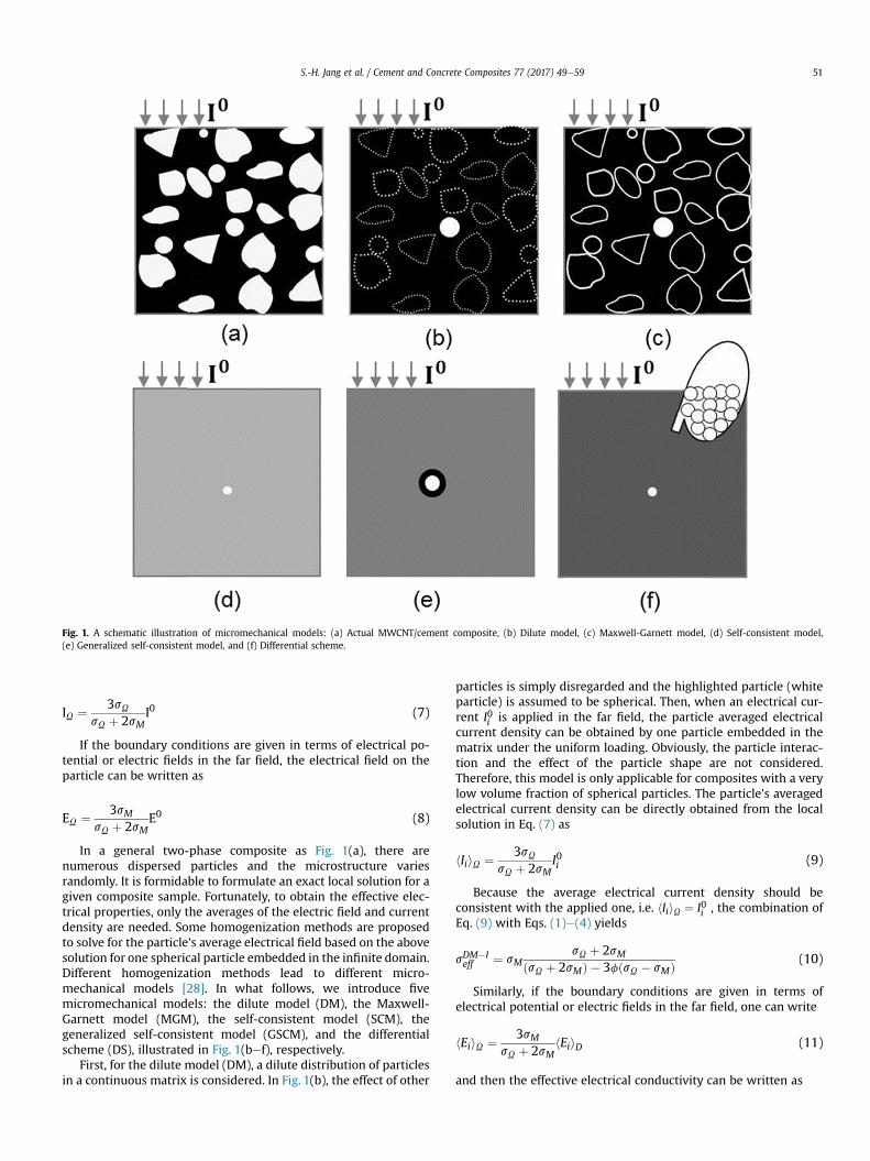
Fig. 1. A schematic illustration of micromechanical models: (a) Actual MWCNT/cement composite, (b) Dilute model, (c) Maxwell-Garnett model, (d) Self-consistent model,(e) Generalized self-consistent model, and (f) Differential scheme.
S.-H. Jang et al. / Cement and Concrete Composites 77 (2017) 49e59 51
IU ¼ 3sUsU þ 2sM
I0 (7)
If the boundary conditions are given in terms of electrical po-tential or electric fields in the far field, the electrical field on theparticle can be written as
EU ¼ 3sMsU þ 2sM
E0 (8)
In a general two-phase composite as Fig. 1(a), there arenumerous dispersed particles and the microstructure variesrandomly. It is formidable to formulate an exact local solution for agiven composite sample. Fortunately, to obtain the effective elec-trical properties, only the averages of the electric field and currentdensity are needed. Some homogenization methods are proposedto solve for the particle's average electrical field based on the abovesolution for one spherical particle embedded in the infinite domain.Different homogenization methods lead to different micro-mechanical models [28]. In what follows, we introduce fivemicromechanical models: the dilute model (DM), the Maxwell-Garnett model (MGM), the self-consistent model (SCM), thegeneralized self-consistent model (GSCM), and the differentialscheme (DS), illustrated in Fig. 1(bef), respectively.
First, for the dilute model (DM), a dilute distribution of particlesin a continuous matrix is considered. In Fig. 1(b), the effect of other
particles is simply disregarded and the highlighted particle (whiteparticle) is assumed to be spherical. Then, when an electrical cur-rent I0i is applied in the far field, the particle averaged electricalcurrent density can be obtained by one particle embedded in thematrix under the uniform loading. Obviously, the particle interac-tion and the effect of the particle shape are not considered.Therefore, this model is only applicable for composites with a verylow volume fraction of spherical particles. The particle's averagedelectrical current density can be directly obtained from the localsolution in Eq. (7) as
hIiiU ¼ 3sUsU þ 2sM
I0i (9)
Because the average electrical current density should beconsistent with the applied one, i.e. hIiiU ¼ I0i , the combination ofEq. (9) with Eqs. (1)e(4) yields
sDM�Ieff ¼ sM
sU þ 2sMðsU þ 2sMÞ � 3fðsU � sMÞ (10)
Similarly, if the boundary conditions are given in terms ofelectrical potential or electric fields in the far field, one can write
hEiiU ¼ 3sMsU þ 2sM
hEiiD (11)
and then the effective electrical conductivity can be written as

S.-H. Jang et al. / Cement and Concrete Composites 77 (2017) 49e5952
sDM�Eeff ¼ sM þ f
3sMðsU � sMÞsU þ 2sM
(12)
Because the dilute distribution of particles is assumed, thismodel is only valid for composites with very small volume fractionsof dispersed phases. Based on two different boundary conditions,two predictions are obtained in Eqs. (10) and (12). Obviously, theyare close to each other when the volume fraction of particles is verysmall. However, when the volume fraction increases to a certainvalue, they are different because the one particle solution is notapplicable any more. The results of Eq. (10) can be divergentbecause the denominator in the equation may reduce to zero (forinstance, as the volume fraction f ¼ ðsU þ 2sMÞ=3ðsU � sMÞ,Eq. (10) is found to diverge).
Secondly, for the Maxwell-Garnett model (MGM) [22], one canderive it in a straightforward method. A particle is embedded intothe matrix with a uniform electric current density the same as thematrix's averaged electric current density. In Fig. 1(c), before thehighlighted particle is embedded in thematrix, due to the existenceof other particles, the electrical current density field surroundingthe highlighted particle is highly distorted. The MGM assumes theelectrical current density in the neighborhood of the particle isequal to the matrix's averaged electric current density. When theparticle is embedded in the matrix, the particle averaged electricalfield can be obtained by considering one particle embedded in thematrix with a uniform current density. The particle's averagedelectric current density is written as
hIiiU ¼ 3sUsU þ sM
hIiiM (13)
The substitution of Eq. (13) into Eq. (4) yields
sMGMeff ¼ sM
ðsU þ 2sMÞ þ 2fðsU � sMÞðsU þ 2sMÞ � fðsU � sMÞ (14)
Similarly, if the particle's average electrical field is considered ashEiiU ¼ 3sM
sUþ2sMhEiiM , one can also derive the effective electrical
conductivity, which is the same as the above.When the volume fraction of particles is fairly high or particles
are clustered, even in the neighborhood of the particle other par-ticles may exist, so the local field in the particle domain can interactwith other particles. Consequently, although MGM provides abetter prediction than DM for most composites, for high volumefractions or a clustered microstructure, it produces a considerabledisparity from the experimental results. Yin and Sun [30] consid-ered the pairwise interaction of randomly dispersed particles andmade some improvements. In addition, in the MGM, the particle isstill assumed to be spherical, so the effect of the particle shape isnot considered. Notice that the MGM model is equivalent to theHashin and Shtrikman lower bounds for sU >sM [32]. If we switchthe material phases, we can similarly obtain the Hashin andShtrikman upper bounds as follows:
sHSUeff ¼ sUðsM þ 2sUÞ � 2ð1� fÞðsU � sMÞðsM þ 2sUÞ þ ð1� fÞðsU � sMÞ (15)
Thirdly, for the self-consistent method (SCM), because themicrostructure is statistically random, the averaged electrical cur-rent density of the particle phase is represented by that of arandomly chosen infinitesimal material point embedded in thecomposite itself, as illustrated in Fig. 1(d). Because the point is sosmall, its effect on the effective material properties of the remain-ing composite is negligible. Therefore, the particle's average elec-trical current density can be obtained by a single infinitesimal
particle embedded in the composite itself under the uniformloading as follows:
hIiiU ¼ 3sUsU þ 2sSCMeff
hIiiD (16)
Because the point can be chosen at any location in the particlephase, this model is applicable for general composites with irreg-ular shapes and a high volume fraction of particles. The combina-tion of Eq. (16) with Eqs. (1)e(4) yields
sSCMeff ¼ 1
f 3sUþ2sSCM
effþ"1� 3fsU
sUþ2sSCMeff
#,sM
(17)
Simplifying the above equation, the effective electric conductivitycan be explicitly solved as
sSCMeff ¼ �aþffiffiffiffiffiffiffiffiffiffiffiffiffiffiffiffiffiffiffiffiffiffiffiffiffiffia2 þ 8sUsM
p4
(18)
where a ¼ ð1� 3fÞsU þ ð3f� 2ÞsM .Fourthly, for the generalized self-consistent model (GSCM), as
shown in Fig. 1(e), the particle's average electrical current field isderived from the solution for a spherical particle embedded in aconcentrical spherical annulus of the matrix of the prescribedvolume fraction, which in turn is embedded in an infinite mediumwith the effective electric properties of the matrix [31]. Therefore,the effective electrical conductivity of the composite can be ob-tained according to the concept of GSCM as: [32,33].
sGSCMeff ¼ sMðsU þ 2sMÞ þ 2fðsU � sMÞðsU þ 2sMÞ � fðsU � sMÞ (19)
Because the neighboring material plays a more important roleon the local electric field of a particle than the far field materialdoes, GSCM uses the solution for a double layered particleembedded in the composite itself to obtain the particle averagedelectric field. Compared to the self-consistent method, although thelocal interaction between the particle and the matrix is considered,the assumption of the spherical shape of the particle and thematrixlayer is imposed, which is not always valid for general composites.Mathematically, it provides the same prediction as the MGMmodelin Eq. (14). Therefore, we will not individually consider it in thefollowing part of this paper.
Fifthly, the differential scheme (DS) was proposed by theobservation that a composite with a finite volume fraction of par-ticles can be fabricated through the process of adding more andmore particles in Fig. 1(f). Start with the pure matrix with sM andvolume V0, add a small volume of particle V1 into the matrix for avolume fraction f1 ¼ V1
V0þV1, the particle's average electrical field
can be obtained from the above the dilute model as
hEiiV1¼ 3sM
sU þ 2sMhEiiD (20)
The average electric field is
hEiiD ¼ f13sM
sU þ 2sMhEiiD þ ð1� f1ÞhEiiM (21)
In consequence, one can obtain

S.-H. Jang et al. / Cement and Concrete Composites 77 (2017) 49e59 53
hEiiM ¼ 11� f1
�1� f1
3sMsU þ 2sM
�hEiiD (22)
and
Table 1Chemical composition of cement.
Oxide Composition(wt.%)
Mineralogical phase composite (wt.%)
CaO 63.7 Tricalcium silicate (C3S) 52.4SiO2 12.9 Dicalcium silicate (C2S) 16.0Fe2O3 7.9 Tricalcium aluminate (C3A) 10.2SO3 5.3 Tetra-calcium Aluminoferrite (C4AF) 8.6Al2O3 4.2 Magnesite 0.3MgO 3.5 Calcite 0.5K2O 0.9 Dolomite 1.2TiO2 0.3ZnO 0.2
hIiiD ¼ f13sM
sU þ 2sMhEiiDsU þ ð1� f1Þ
11� f1
�1� f1
3sMsU þ 2sM
�hEiiDsM ¼ hEiiD
�3f1sMsUsU þ 2sM
þ�1� f1
3sMsU þ 2sM
�sM
�(23)
Therefore, we obtain the incremental of the effective electric con-ductivity is
s0eff ¼ sM þ sM
�3f1
sU � sMsU þ 2sM
�(24)
Ds0eff ¼ f13sM
sU þ 2sMðsU � sMÞ (25)
Treat the new composite as a matrix with seff , add another smallvolume of particles, and update the volume fraction and effectiveelectrical conductivity. Step by step, one can cumulate the overallvolume fraction of the particles to a finite number less than 100%.From step i to step iþ 1, the volume of the particle increases fromV1 to Viþ1 with an incrementDVi, so the volume fractions at the twosteps are written
fiþ1 ¼ Vi þ DVi
V0 þ Vi þ DVi; fi ¼
Vi
V0 þ Vi(26)
The volume fraction increment is written
Dfi ¼ fiþ1 � fi ¼ ð1� fiÞDVi
V0 þ Vi þ DVi(27)
At step i, the effective conductivity is written sieff . With the incre-mental volume of particles, similarly to Eq. (10), one can
Dsiþ1eff ¼ DVi
V0 þ Vi þ DVi
3sieffsU þ 2sieff
�sU � sieff
�
¼ Dfi
1� fi
3sieffsU þ 2sieff
�sU � sieff
�(28)
Considering DVi can be an infinitesimal value, the above equationcan be rewritten in the differential form as
dseffdf
¼ 11� f
3seffsU þ 2seff
�sU � seff
�(29)
When f ¼ 0; seff ¼ sM . Therefore, one can write the effectiveelectrical conductivity as
seff ¼ sU
8<:24
ffiffiffiffiffiffiffiffiffiffiffiffiffiffiffiffiffiffiffiffiffiffiffiffiffiffiffiffiffiffiffi�b3
�3
þ�b2
�2s
��b2
�351=3
� b3
24
ffiffiffiffiffiffiffiffiffiffiffiffiffiffiffiffiffiffiffiffiffiffiffiffiffiffiffiffiffiffiffi�b3
�3
þ�b2
�2s
��b2
�35�1=39=;þ sU (30)
where b ¼ ð1� fÞ3ð1� sM=sUÞ3sU
sM.
Notice that the differential scheme is a general approach andcan be applicable to different micromechanical models. In theabove, each infinitesimal incremental step essentially uses thedilute model of Eq. (12) and overall an explicit analytical solution isprovided in Eq. (30). If other models are used, different predictionsmay be obtained. For example, if Eq. (10) is used, one can replace1=s as a new variable, say resistance, to set up the differentialequation and eventually to calculate the effective electrical con-ductivity, which is the same as Eq. (30). However, when othermodels are used, analytical formulation may not exist but numer-ical solution will be possible.
3. Experiments
3.1. Materials and sample preparation
Type I ordinary Portland cement was used from Lafarge. Table 1shows the chemical properties of the cement. Pristine MWCNTswere purchased from Nanolab, USA as chemically treated MWCNTsmay hamper the hydration of cement in the curing process [34].The commercial MWCNT had a carbon purity >85%, an averagediameter of 20.0 nm, and length of 12.5 mm, as shown in Table 2.Fig. 2 showed SEM image of as-received MWCNTs where lots ofagglomeration exists due to the van der Waals interaction [35].
The uniform dispersion of MWCNTs is very important in pre-paring conductivematerials. In this study, MWCNTs were dispersedin distilled water using a horn-type ultrasonication (Fisher Scien-tific, USA) for 30 min on a pulse mode (20 s on/20 s off). A totalenergy of 20,000 J was used in ultrasonication for each specimen.

Table 2Physical properties of MWCNTs.
Properties Values
Density 1.8 g/cm3
Surface area 250e300 m2/gDiameter 10e30 nmLength 5e20 mmElectrical conductivity 1 � 105 S/mPurity >85.0 wt%
Fig. 2. SEM image of dispersed MWCNTs in water.
S.-H. Jang et al. / Cement and Concrete Composites 77 (2017) 49e5954
The suspension of MWCNTs in water was kept in an ice bath duringthe sonication to prevent damage from the heat. After the soni-cation, the cement was mixed with the MWCNT suspension (0,0.05, 0.10, 0.50, and 1.00% by cement weight) for about 5 min. Afterpouring the mixture into cubic molds with the edge length of25.4 mm, vibrationwas applied for compaction and densification ofthe cement paste. All specimens were demolded in 24 h. Then, thespecimens were cured in a water bath at room temperature for 28days. After the specimens were ready for tests, different moistureconditions were applied for the electrical characterization.
3.2. Characterization
The distribution of MWCNTs in cement hydrates was observedusing a scanning electron microscope (JEOL SEM-6400). After 28days, the specimens were weighed before heating them in an ovenat 100 ± 5 �C for a specific period of time in order to producedifferent moisture contents. Themoisture content of a specimen,w,is calculated as
w ¼ wt �wd
wd� 100 ðwt:%Þ (31)
where wt is the weight of the specimen to be evaluated and wd isthe weight of the specimen after a full drying process.
The two point-probe method was employed to measure thevolume resistance due to difficulty in installing electrodes insidecement paste as well as the oxidation of electrodes in the four pointprobe method [36,37]. The volume resistance of the specimens wasmeasured using a Fluke 8846A multimeter at room temperature.Silver paint was applied at both electrodes of the specimen toreduce the contact resistance between the test probe and thesample surface. Notice that because the contact resistance is muchsmaller than the resistance of samples, the advantages of the fourpoint-probe method over the two-probe method are not
significant. A customized test fixture with copper plates was alsoused to measure the resistance of the specimens under the sameconditions in terms of the pressure and the temperature. Theelectrical conductivity (s) of the specimens was calculated from thebulk resistance by
s ¼ LRA
(32)
where L is the length between the electrodes, A is the cross-sectional area of the specimens, and R is the volume resistance.Fig. 3 showed the sample preparation and the experimental setupfor the electrical conductivity of the composites.
4. Results and discussion
4.1. Microstructure of the MWCNT/cement paste
Although many researchers have proposed different dispersionmethods for MWCNTs in cementitious-based composites, it is still achallenging task due to the polarity of water and the alkalinity ofcement [38,39]. This explains the agglomeration of MWCNTs thathas been observed in this study. Fig. 4 shows the dispersion ofMWCNT in cement hydrates (Fig. 4(a)) and highlights an areawith ared dash line where many MWCNTs have agglomerated (Fig. 4(b)).This non-uniform distribution of MWCNTsmay significantly reducethe overall electrical conductivity of MWCNT/cement paste com-posites. In this study, we consider different phases such as thecement hydrate, air voids, MWCNTs, and moisture in order topredict the effective electrical conductivity of MWCNT/cementpaste. First, one can simulate cement paste prepared at differentporosities by using a two-phase model with one phase being thecement hydrates and the other being the pores. Then, moisture isintroduced into the composite to investigate the effect of moistureon electrical conductivity of MWCNT/cement paste. By consideringthe cement paste as a uniform matrix and introducing MWCNTsinto the matrix, one can also simulate MWCNT/cement paste.Finally the combination of the three steps will provide a predictionto the effective conductivity giving the porosity, moisture content,and MWCNT content.
4.2. Comparison of micromechanical models
Overall, because MWCNTs as well as the moisture contained inthe cement hydrates are generally irregular shapes such as angular,flat, or sub-rounded, whereas DM, MGM, and GSCM are based onthe assumption of spherical particles, the accuracy of these modelsis questionable. Although SCM does not consider the interactionbetween the cement hydrates and the MWCNTs as well as mois-ture, it offers some flexibility for the particle shape and volumefraction. It is noted that all these models are based on the solutionfor one spherical particle embedded in an infinite domain, so thedirect interaction between particles is not considered. Fig. 5 showsa comparison of various models for the relative effective electricalconductivity (sfiller=smatrix). As expected, the Parallel and Seriesmodels provide the highest and lowest values, respectively and theDM also predicts low values as well. Out of the DS, SCM, MGM, andGSCM models, the MGM provides the lowest prediction whereasthe SCM shows the highest prediction. At low volume fraction,there is no significant difference between the DM, MGM, SCM,GSCM, and DS models, regardless of the conductivity of fillers.Because the Parallel and Series only provide a large range of theupper and lower bounds instead of the specific predictions of theeffective electrical conductivities, we will not include them thefollowing comparison.

Fig. 3. Volume resistance measurement of MWCNT/cement composite specimens. (a) Silver painted specimens and (b) Setup for resistance measurement.
Fig. 4. MWCNT agglomeration in cement hydrates.
Fig. 5. Comparison of various models for the effective electrical conductivity (a) sfiller=smatrix ¼ 10 and (b) sfiller=smatrix ¼ 1;000.
S.-H. Jang et al. / Cement and Concrete Composites 77 (2017) 49e59 55

Fig. 7. Influence of moisture on electrical conductivity of MWCNT/cement paste.
S.-H. Jang et al. / Cement and Concrete Composites 77 (2017) 49e5956
4.3. Influence of porosity in cement paste
The electrical conductivity of cement paste is associated withthe pore structure, which is related to the water-to-cement ratio.The porosity of cement paste as a function of the water-to-cementratio was obtained by Hansen's model [40]:
fp ¼ w=c� 0:17w=cþ 0:32
(33)
Cement paste with 0.09% of MWCNTs were prepared at fivewater-to-cement ratios (0.4, 0.5, 0.6, 0.7, and 0.8) and the effectiveelectrical conductivity of the dry samples were measured usingthe method discussed in Section 3.2. Fig. 6 shows a comparisonof the various micromechanics based models with our experi-mental results. Note that the electrical conductivity of air voids (sa )were assumed to be perfectly insulting inclusions assa ¼ 1:0� 10�15S=m that is the similar value of polymer [41] andthe electrical conductivity of the cement hydrates (sc ) was ob-tained as sc ¼ 2:0� 10�5S=m by the curve-fitting with experi-mental data due to a lack of data for pure cement hydrate. It can beseen that the electrical conductivity of cement paste decreases withan increase in thewater-cement ratio (porosity). All models providefairly consistent predictions with the experimental results, but theMGMperforms the best. Themicro-pores in cement paste generallyare discrete spheres in the cement hydrate, which agree with theassumptions of the MGM model very well. Therefore, the modelprovides excellent predictions of the experiments (see Fig. 7).
Fig. 8. Comparison of measured and predicted electrical conductivity of MWCNT/cement paste.
4.4. Influence of moisture in cement paste
Moisture is a significant factor that affects the electrical con-ductivity of cementitious-based composites because the electricalconductivity of moisture is much higher than the solid phases incement paste. Here, we simulate the effective electrical conduc-tivity of cement paste with 0.09% of MWCNTs at a water-to-cementratio of 0.5 with different volume fractions of moisture (fm ¼ 0%,11%, 19%, 26%, 32%, and 39% by cement volume). The electricalconductivity of water is approximately sw ¼ 10�3S=m when itcontains someminerals or when ions from the samples are leachedinto water. Fig. 8 shows the effective electrical conductivity of thecomposite using various models. All models except for the parallel,
Fig. 6. Comparison of various models with experimental results for dry cement paste.
series, and SCM provide good predictions compared to the exper-imental results. In particular, GSCM and MGM are the best modelsto simulate the effect of moisture in MWCNT/cement paste.Therefore, the MGM can capture the effect of the porosity andmoisture on the effective electrical conductivity of the cementpaste.
4.5. Influence of MWCNT
The electrical conductivity of MWCNT is generally about 106 S/mbut it has been reported that the electrical conductivity can belower in the actual application, say in the range of 104 � 105S=m[42], due to damage from the fabrication procedure. The electricalconductivity of cement paste was obtained from our experimentalresults. Six samples with a water-to-cement ratio of 0.5 were pre-pared at different volume fractions of MWCNTs (0%, 0.09%, 0.17%,0.43%, 0.85%, and 1.69%). The electrical conductivity of theMWCNTswas taken as sCNT ¼ 1:0� 104S=m. Fig. 8 displays the predictionsfor the micro-mechanical based models, which shows that none ofthe models provide a good prediction of the experimental results.Except for the parallel one, all other models significantly

S.-H. Jang et al. / Cement and Concrete Composites 77 (2017) 49e59 57
underestimate the effective electrical conductivity of the compos-ites. This is attributed to the fact that those models do not considerthe connectivity amongst MWCNTs. In addition, the higher elec-trical conductivity of MWCNT/cement paste compared to purecement paste is due to the high aspect ratio of MWCNTs, makingcontact points between MWCNTs that act as electron paths forbetter electrical conductivity.
To capture the effect of electron paths through the MWCNT, wehave developed the eight-chain model that is capable to predict theeffective electrical conductivity of the composites with well-networked multi-walled carbon nanotubes [43]. However, wehave observed that the MWCNT is commonly agglomerated incement paste with a certain portion contributing to the network.Therefore, in this study, we proposed a mixed model to simulateoverall electrical conductivity of MWCNT/cement paste. For fullydispersed MWCNT in cement matrix, the eight-chain model wasused and will be elaborated in the next subsection. For agglomer-ation of MWCNTs in the matrix, MGM in Eq. (33) was used as itexhibits excellent accuracy for the discrete particles in a continuousmatrix. Therefore, the electric conductivity will be the sum of thetwo parts:
seff ¼ fmixsnetwork þ ð1� fmixÞsagg (34)
where fmix ¼ hfCNT and h is a degree of fully dispersed MWCNTfrom the total volume fraction fCNT , which decreases with the in-crease of the volume fraction of MWCNT as the same dispersioneffort. For simplicity, a linear function is assumed ash ¼ k0 � k1fCNT with k0 and k1 being the fitting parameter todescribe dispersion effort. Therefore we can write
fmix ¼ ðk0 � k1fCNT ÞfCNT (35)
Fig. 9 shows the effective electrical conductivity of MWCNT/cement paste based on the mixed model. The result highly dependson the degree of well-dispersed MWCNTs. In this study, we ob-tained good agreement with experimental data when dispersedstate was used as h ¼ 0:000004� 0:000284f, meaning that severeagglomerations of MWCNTs exist, which significantly lower theelectrical conductivity compared to composites consisting of a full-networked CNT/polymer composites [43e45]. Note that when thevolume fraction of the MWCNTs is high, say 1.0% in Fig. 9, theexperimental result is much lower than the prediction due to
Fig. 9. Mixed model for effective electrical conductivity MWCNT/cement paste.
severe agglomeration of MWCNTs, which has been commonlyfound in the literature [39,46].
4.6. Prediction of MWCNT/cement composites
It has been observed that the effective electrical conductivity ofMWCNT/cement composite depends on air voids, MWCNTs, andmoisture. Two-phase based micromechanical models, in particular,MGM, predict the electrical conductivity of MWCNT/cement com-posites at various water-to-cement ratios and amounts of moisture.On the other hand, amixedmodel constructed from the eight-chainmodel and the MGM provided good predictions for the addition ofMWCNTs to the cement composite. When multiple material phasesare considered, one can simulate cement paste prepared atdifferent porosities andmoisture contents andMWCNTcontents byusing the combination of the three steps, which are correspondingto the above three cases. Given a MWCNT/cement composite withthe porosity fp, moisture content fm, and MWCNT content fCNT , ifthe dispersion effort has been well described by the paramaters k0and k1, the effective electric conductivity can be calculated by thefollowing procedure:
First, the effective electric conductivity of dry cement pastewithporosity fp is calculated by the MGM model
s1 ¼ scðsa þ 2scÞ þ 2fpðsa � scÞðsa þ 2scÞ � fpðsa � scÞ (36)
Then the effect of moisture will be evaluated by the MGM modelagain as
s2 ¼ s1sw þ 2s1
þ 2fmsw � s1
sw þ 2s1
� fmsw � s1
(37)
At the last step, the MWCNTs will be considered by the mixedmodel in Eq. (34) by taking the cement paste with s2 as the matrix.Therefore, we obtained the electrical conductivity of agglomeratedand networked MWCNTs such as
sagg ¼ s2sCNT þ 2s2
þ 2fCNT ð1� fmixÞsw � s2
sw þ 2s2
� fCNT ð1� fmixÞsw � s2
(38)
snetwork ¼8<: ffiffiffi
3p
pD2
fCNT
!1=2
,Reff
9=;
�1
(39)
whereD is a diameter of MWCNTand Reff is total resistance in a unitcell which consisting of an intrinsic resistance of MWCNT and acontact resistance between MWCNTs. All of the parameters thatwere used are the same as given by Jang and Yin [43]. Eventually,we can use the results of Eqs. (38) and (39) in Eq. (34) to obtain theeffective electrical conductivity of the composites. Fig. 10 shows arelationship between measured and predicted electrical conduc-tivity of cementitious-based composite with moisture andMWCNTs. The proposed model provides very consistent pre-dictions with the experimental results and the overall root meansquared error (RMSE) is 0.0866, which is ~5% of the average elec-trical conductivity of all samples. Adding MWCNTs can improve theelectrical conductivity significantly but the moisture exhibits amore significant effect on the overall conductivity. Therefore, itshould be very cautions to use MWCNT/cementitious-based com-posites for sensing with electrical conductivity change because theenvironmental factor of moisture may play a dominant role in themeasurement. The proposed model can successfully capture theeffect of both MWCNTs and moisture.

Fig. 10. Relationship between the observed and predicted electrical conductivity interms of porosity, moisture, and MWCNTs.
S.-H. Jang et al. / Cement and Concrete Composites 77 (2017) 49e5958
Notice that adding MWCNTs may change the effective porosityand moisture content as it changes the overall volume of thecomposite in principle. However, because the MWCNT content isalways small (~1%), the difference between two cases is negligible.Therefore, we can use the same input parameters although in thefirst two steps, the volume fractions should be calculated based onthe cement paste without MWCNTs.
5. Conclusions
Several micromechanical models for effective electrical con-ductivity of cementitious-based composite with air void, MWCNT,and moisture are reviewed and examined through the analyticalderivation and comparison with our experiments. The under-standing can be extended to other physical properties ofcementitious-based composite such as thermal conductivity. Themain conclusions are provided as follows:
(1) The MWCNT agglomerations were observed in MWCNT/cement paste due to the polarity of water and alkalinity ofcement, significantly reducing its electrical conductivity andthus affecting the accuracy of conventional micromechanics.
(2) The MGMmodel provided excellent accuracy to evaluate theeffect of discrete particle phase, such as air voids and mois-ture. However, all micromechanical models failed to capturethe effect of electron path through the MWCNT network onthe electrical conductivity of the MWCNT/cement paste dueto MWCNT agglomerations.
(3) The mixed model based on the eight-chain model forMWCNT network and MGM for MWCNT agglomeration wasproposed to simulate the effect of MWCNT agglomeration inthe MWCNT/cement pastes.
(4) A three-step micromechanical model was proposed to pre-dict the effective electrical conductivity of MWCNT/cementpastes. The proposed model provided very good agreementwith experimental results with an overall root mean squarederror (RMSE) at 0.0866, which is ~5% of the average electricalconductivity of all samples. The research results showed thatmoisture may significantly affect the accuracy of the sensingtechnology with smart cementitious-based composites un-less this factor is well quantified.
Acknowledgements
The authors would like to thank Dr. Liming Li and Dr. FangliangChen for their valuable assistance with the experiments. This workis sponsored by the National Science Foundation CMMI 1301288,whose support is gratefully acknowledged.
References
[1] M.S. Konsta-Gdoutos, Z.S. Metaxa, S.P. Shah, Highly dispersed carbon nano-tube reinforced cement based materials, Cem. Concr. Res. 40 (Jul 2010)1052e1059.
[2] T. Nochaiya, A. Chaipanich, Behavior of multi-walled carbon nanotubes on theporosity and microstructure of cement-based materials, Appl. Surf. Sci. 257(Jan 1 2011) 1941e1945.
[3] R.K. Abu Al-Rub, A.I. Ashour, B.M. Tyson, On the aspect ratio effect of multi-walled carbon nanotube reinforcements on the mechanical properties ofcementitious nanocomposites, Constr. Build. Mater. 35 (Oct 2012) 647e655.
[4] Y. Hu, D.N. Luo, P.H. Li, Q.B. Li, G.Q. Sun, Fracture toughness enhancement ofcement paste with multi-walled carbon nanotubes, Constr. Build. Mater. 70(Nov 15 2014) 332e338.
[5] S.H. Wen, D.D.L. Chung, Electrical-resistance-based damage self-sensing incarbon fiber reinforced cement, Carbon 45 (Apr 2007) 710e716.
[6] H.K. Kim, I.W. Nam, H.K. Lee, Enhanced effect of carbon nanotube on me-chanical and electrical properties of cement composites by incorporation ofsilica fume, Compos. Struct. 107 (Jan 2014) 60e69.
[7] H. Li, Q.Q. Zhang, H.G. Xiao, Self-deicing road system with a CNFP high-efficiency thermal source and MWCNT/cement-based high-thermal conduc-tive composites, Cold Regions Sci. Technol. 86 (Feb 2013) 22e35.
[8] H. Li, Q.Q. Zhang, H.G. Xiao, Analytic investigations of CNFP-based self-deicingroad system on the deicing performance, Cold Regions Sci. Technol. 103 (Jul2014) 123e132.
[9] S.H. Wen, D.D.L. Chung, Partial. replacement of carbon fiber by carbon black inmultifunctional cement-matrix composites, Carbon 45 (Mar 2007) 505e513.
[10] F. Azhari, N. Banthia, Cement-based sensors with carbon fibers and carbonnanotubes for piezoresistive sensing, Cem. Concr. Compos. 34 (Aug 2012)866e873.
[11] B.G. Han, X. Yu, E. Kwon, A self-sensing carbon nanotube/cement compositefor traffic monitoring, Nanotechnology 20 (Nov 4 2009).
[12] F. Ubertini, A.L. Materazzi, A. D'Alessandro, S. Laflamme, Natural frequenciesidentification of a reinforced concrete beam using carbon nanotube cement-based sensors, Eng. Struct. 60 (Feb 2014) 265e275.
[13] S.H. Jang, H.M. Yin, Effect of aligned ferromagnetic particles on strain sensi-tivity of multi-walled carbon nanotube/polydimethylsiloxane sensors, Appl.Phys. Lett. 106 (Apr 6 2015).
[14] R. Sriravindrarajah, R. Swamy, R. Sriravindrarajah, R. Swamy, Development ofa Conductivity Probe to Monitor Setting Time and Moisture Movement inConcrete, 1982.
[15] G. Woelfl, K. Lauer, G. Woelfl, K. Lauer, The Electrical Resistivity of Concretewith Emphasis on the Use of Electrical Resistance for Measuring MoistureContent, 1979.
[16] A. Princigallo, K. van Breugel, G. Levita, Influence of the aggregate on theelectrical conductivity of Portland cement concretes, Cem. Concr. Res. 33 (Nov2003) 1755e1763.
[17] N. Schwarz, M. DuBois, N. Neithalath, Electrical conductivity based charac-terization of plain and coarse glass powder modified cement pastes, Cem.Concr. Compos. 29 (Oct 2007) 656e666.
[18] Z.Y. Liu, Y.S. Zhang, L.B. Liu, Q. Jiang, An analytical model for determining therelative electrical resistivity of cement paste and C-S-H gel, Constr. Build.Mater. 48 (Nov 2013) 647e655.
[19] M. Saleem, M. Shameem, S.E. Hussain, M. Maslehuddin, Effect of moisture,chloride and sulphate contamination on the electrical resistivity of Portlandcement concrete, Constr. Build. Mater. 10 (Apr 1996) 209e214.
[20] H.K. Kim, I.S. Park, H.K. Lee, Improved piezoresistive sensitivity and stability ofCNT/cement mortar composites with low water-binder ratio, Compos. Struct.116 (Sep-Oct 2014) 713e719.
[21] B. Sareni, L. Krahenbuhl, A. Beroual, C. Brosseau, Effective dielectric constant ofrandom composite materials, J. Appl. Phys. 81 (Mar 1 1997) 2375e2383.
[22] J.C.M. Garnett, Colours in metal glasses and in metallic films, Series a-Con-taining Papers of a Mathematical or Physical Character, Philosophical Trans. R.Soc. Lond. 203 (Sep 1904) 385e420.
[23] R. Landauer, Electrical conductivity in inhomogeneous media, AIP ConferenceProceedings, vol. 40, pp. 2e45, 1978.
[24] T.J. Fiske, H.S. Gokturk, D.M. Kalyon, Percolation in magnetic composites,J. Mater. Sci. 32 (1997) 5551e5560.
[25] R. Pelster, Dielectric spectroscopy of confinement effects in polar materials,Phys. Rev. B 59 (Apr 1 1999) 9214e9228.
[26] H.M. Yin, G.H. Paulino, W.G. Buttlar, L.Z. Sun, Effective thermal conductivity oftwo-phase functionally graded particulate composites, J. Appl. Phys. 98 (Sep15 2005).
[27] H.M. Yin, G.H. Paulino, W.G. Buttlar, L.Z. Sun, Effective thermal conductivity offunctionally graded particulate nanocomposites with interfacial thermal

S.-H. Jang et al. / Cement and Concrete Composites 77 (2017) 49e59 59
resistance, J. Appl. Mechanics-Transactions Asme 75 (Sep 2008).[28] H.M. Yin, W.G. Buttlar, G.H. Paulino, H. Di Benedetto, Assessment of existing
micro-mechanical models for asphalt mastics considering viscoelastic effects,Road Mater. Pavement Des. 9 (Jan-Mar 2008) 31e57.
[29] H.M. Yin, B. Lai, Visco-elastic characterisation of zeolite modified asphaltbinder considering phase transformation and air void interaction, Road Mater.Pavement Des. 13 (2012) 279e299.
[30] H.M. Yin, L.Z. Sun, Magnetic properties of randomly dispersed magneticparticulate composites: a theoretical study, Phys. Rev. B 72 (Aug 2005).
[31] T. Miloh, Y. Benveniste, A generalized self-consistent method for the effectiveconductivity of composites with ellipsoidal inclusions and cracked bodies,J. Appl. Phys. 63 (Feb 1 1988) 789e796.
[32] Z. Hashin, S. Shtrikman, A variational approach to the theory of the elasticbehaviour of polycrystals, J. Mech. Phys. Solids 10 (1962) 343e352.
[33] J.K. Lee, J.G. Kim, Derivation of governing equation for predicting thermalconductivity of composites with spherical inclusions and its applications,Phys. Lett. A 375 (Oct 3 2011) 3739e3744.
[34] S. Musso, J.M. Tulliani, G. Ferro, A. Tagliaferro, Influence of carbon nanotubesstructure on the mechanical behavior of cement composites, Compos. Sci.Technol. 69 (Sep 2009) 1985e1990.
[35] L. Vaisman, H.D. Wagner, G. Marom, The role of surfactants in dispersion ofcarbon nanotubes, Adv. Colloid Interface Sci. 128 (Dec 21 2006) 37e46.
[36] S.H. Wen, D.D.L. Chung, Effect of admixtures on the dielectric constant ofcement paste, Cem. Concr. Res. 31 (Apr 2001) 673e677.
[37] D.J. Yang, C.G. Lu, H.M. Yin, I.P. Herman, Thermoelectric performance of PbSequantum dot films, Nanoscale 5 (2013) 7290e7296.
[38] K. Ke, Y. Wang, Y. Luo, W. Yang, B.H. Xie, M.B. Yang, Evolution of agglomerate
structure of carbon nanotubes in multi-walled carbon nanotubes/polymercomposite melt: a rheo-electrical study, Compos. Part B-Eng. 43 (Dec 2012)3281e3287.
[39] O. Mendoza, G. Sierra, J.I. Tobon, Effect of the reagglomeration process ofmulti-walled carbon nanotubes dispersions on the early activity of nanosilicain cement composites, Constr. Build. Mater. 54 (Mar 15 2014) 550e557.
[40] T.C. Hansen, Physical structure of hardened cement paste. A classicalapproach, Mater. Struct. 19 (1986) 423e436.
[41] H.S. Wong, A.M. Pappas, R.W. Zimmerman, N.R. Buenfeld, Effect of entrainedair voids on the microstructure and mass transport properties of concrete,Cem. Concr. Res. 41 (Oct 2011) 1067e1077.
[42] W.S. Bao, S.A. Meguid, Z.H. Zhu, M.J. Meguid, Modeling electrical conductiv-ities of nanocomposites with aligned carbon nanotubes, Nanotechnology 22(Dec 2 2011).
[43] S.H. Jang, H.M. Yin, Effective electrical conductivity of carbon nanotube-polymer composites: a simplified model and its validation, Mater. Res. Ex-press 2 (Apr 2015).
[44] F.H. Gojny, M.H.G. Wichmann, B. Fiedler, I.A. Kinloch, W. Bauhofer,A.H. Windle, et al., Evaluation and identification of electrical and thermalconduction mechanisms in carbon nanotube/epoxy composites, Polymer 47(Mar 8 2006) 2036e2045.
[45] S. Farjana, F. Toomadj, P. Lundgren, A. Sanz-Velasco, O. Naboka, P. Enoksson,Conductivity-dependent strain response of carbon nanotube treated bacterialnanocellulose, J. Sensors 2013 (2013) 7. Article ID 741248, http://dx.doi.org/10.1155/2013/741248.
[46] S.H. Jang, S. Kawashima, H.M. Yin, Influence of carbon nanotube clustering onmechanical and electrical properties of cement pastes, Materials 9 (Apr 2016).