multifunctional corrosion-resistant foamed well cement composites
TRANSCRIPT

1 | US DOE Geothermal Office eere.energy.gov
Public Service of Colorado Ponnequin Wind Farm
Geothermal Technologies Office 2013 Peer Review
Multifunctional Corrosion-resistant Foamed Well Cement Composites Project Officer: Dan King/Greg Stillman Total budget: $300 K April 24 , 2013
Principal Investigator: Dr. Toshifumi Sugama Co-PI; Dr. Tatiana Pyatina Presenter Name: Dr. Toshifumi Sugama
This presentation does not contain any proprietary
confidential, or otherwise restricted information.
Microstructure developed in conventional foamed (left) and corrosion-
resistant foamed cements (right)

2 | US DOE Geothermal Office eere.energy.gov
Relevance/Impact of Research
Objectives: The thrust of this project is to develop cost-effective multifunctional
corrosion-resistant foamed cement composites for carbon steel-based
casings in EGS wells, to characterize their properties, and to transfer
developed technology to cost-sharing industrial partners.
Impact: When a field-applicable corrosion-resistant foamed well cement
possessing all required properties is formulated, it will provide the following
five bottom-line benefits for EGS wellbore integrities:
1. Extension of the carbon steel-based casing’s lifecycle;
2. Reduction of capital investment instead of using very expensive corrosion-
resistant titanium and zirconium alloys, stainless steel or clad materials;
3. Decrease in well operation and maintenance (O&M) costs;
4. Reduction of substantial expenditures for abandoning, re-drilling, re-
cementing, reconstructing or repairing wells brought about by the failure of
well cement;
5. Cost-effective cements will reduce some capital investment.

3 | US DOE Geothermal Office eere.energy.gov
Scientific/Technical Approach
The field applicable multifunctional cements will be formulated to meet
the following thirteen material criteria:
1) Slurry density of foamed cement, < 1.3 g/cm3;
2) Maintenance of pumpability for at least 3 hours;
3) Thermal and hydrothermal stability >300C
4) Corrosion rate of carbon steel casing < 70 milli-inch/year;
5) Compressive strength, > 1000 psi after five superheating-cooling
cycles (one cycle: 500C heat for 24 hrs and 25C water-quenching for
4 hrs) as thermal shock resistance test;
6) Water permeability, < 1 x 10 -4 Darcy;
7) Bond strength to steel casing and granite rock, > 30 psi;
8) Resistance to CO2-induced mild acid (pH ~ 5.0) at 300C, < 5 wt%
loss after 30 days exposure;
9) Fracture toughness, > 0.006 MN/m3/2 at 300C, 24 hour-curing time;
10) No shrinkage;
12) Thermal conductivity < 0.5 W/m.K;
13) Total raw material cost < $0.20/lb.

4 | US DOE Geothermal Office eere.energy.gov
Accomplishments, Results and Progress
Original Planned Milestone/ Technical
Accomplishment
Actual Milestone/Technical Accomplishment
Date Completed
Task 1. Develop thermal shock-resistant
cements
Completed.
S. Gill, T. Pyatina, and T. Sugama “Thermal
shock-resistant cement,” GRC Transactions,
36 (2012) 445-451.
2012 GRC Best Presentation Award
March 2012
Task 2. Develop formulation of air-foamed
light weight cements
Completed.
Jun 2012
Task 3. Develop corrosion inhibitors for
foamed cement
Completed.
T. Sugama, S. Gill, T. Pyatina, R. Keese, A.
Khan, and D. Bour “Corrosion-resistant
foamed cements for carbon steel,” BNL
informal report, January (2013).
December 2012
Task 4. Deliver interim report to DOE Completed. Two reports December 2012
Task 5. Complete technology transfer to
cost-sharing industrial partners
Completed. Schlumberger, Baker Hughes, and
Geodynamics
December 2012

5 | US DOE Geothermal Office eere.energy.gov
Accomplishments, Results and Progress
Synthesis of Thermal Shock-resistant Cement (TSRC)
Hydrothermal synthesis of new cement consists of three cementitious
phases, hydro-garnet, hydro-ceramic, and hydro-Al oxide, from starting
materials including refractory calcium aluminate cement (RC), Class F
fly ash, and sodium silicate
CaO.Al2O3
CaO.2Al2O3
3Al2O3.2SiO2
SiO2H2O
H2O
Na2O.SiO2
C
Ca5Al2(OH)12
Ca3Al2Si2O8(OH)4
++
+
hydrothermal reaction at 200 C
Na4Al3Si3O12(OH)
gamma-AlOOH
Hydro-garnet
Hydro-ceramic
Hydro-garnet
RC
Class F fly ash
Hydrogrossular
Katoite
Hydroxysodalite
hydrothermal reaction at 200°
°
Hydro-Al oxide
boehmite
1/1 NaO2/SiO2 ratio

6 | US DOE Geothermal Office eere.energy.gov
Accomplishments, Results and Progress
Thermal shock-resistance test (one cycle: 500C annealing for
24 hrs + 25C water-quenching for 5 hr)
Heat-water quenching cycles
0 1 2 3 4 5
Co
mp
ress
ive
stre
ng
th,
psi
1000
2000
3000
4000
5000
6000
7000
100/0 Class G/additive
65/35 Class G/Quartz fluor
100/0 RC/Fly ash F
80/20 RC/Fly ash F
60/40 RC/Fly ash F

7 | US DOE Geothermal Office eere.energy.gov
Accomplishments, Results and Progress
Phase compositions formed in TSRC after 5 cycle testing
Ca3Al2Si2O8(OH)4 Ca5Al2(OH)12
CaCO3
+ Na4Al3Si3O12(OH) gamma-AlOOH
Hydro-garnet Hydro-ceramicHydro-garnet
+ +
Hydrogrossular Katoite Hydroxysodalite
500°C, CO2
Na8Al6Si6O24CO3
Carbonated sodalite
as nano-scale crystal
gamma-Al2O3>>+ + +
Boehmite
Hydro-Al oxide
1 µm
8 | US DOE Geothermal Office eere.energy.gov
Accomplishments, Results and Progress
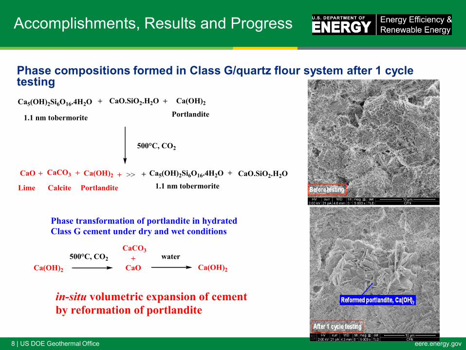
Phase compositions formed in Class G/quartz flour system after 1 cycle testing
CaO
Ca(OH)2
Ca5(OH)2Si6O16.4H2O
CaCO3 Ca(OH)2
CaO
CaO.SiO2.H2O
CaCO3
Ca5(OH)2Si6O16.4H2O
Ca(OH)2
Ca(OH)2
CaO.SiO2.H2O
1.1 nm tobermorite
+ +
Portlandite
500°C, CO2
Lime
+
Portlandite
+ >> + +
1.1 nm tobermorite
+
Calcite
500°C, CO2 + water
in-situ volumetric expansion of cement
by reformation of portlandite
Phase transformation of portlandite in hydrated
Class G cement under dry and wet conditions

9 | US DOE Geothermal Office eere.energy.gov
Accomplishments, Results and Progress
Cool water-thermal stress cycle test for cement sheaths (One cycle: 350C
heated-25C cool water passing in tube)
~25C water
Class G/quartz flour
cement sheath after
1 cycle
New cement sheath
after 5 cycles
Shear bonding strength at interfaces between
cement and casing before
and after 5 cycle testing
Class G
/quartz
flour
60/40 R
C/Cla
ss F fl
y ash
40/60 R
C/Cla
ss F fl
y ash
Sh
ea
r b
on
din
g s
tre
ng
th,
ps
i
0
20
40
60
80
100
Before test
After 5-cycle test

10 | US DOE Geothermal Office eere.energy.gov
Accomplishments, Results and Progress
Corrosion-resistant foamed TSRC for carbon steel
CH3
Ca2+
+ 2 OH-
COOH or COOR
CH3
COO-
Ca2+ -
OOC
CH3
-[-CH2-C-]-n2 +
-[-CH2-C-]-n -[-C-CH2-]-n
R: C2H5 or C4H9
+ 2H2O + ROH
(in cement) >150oC
High-temperature Corrosion Inhibitor: Acrylic polymer (AP)
Thermal stability of Ca-complex AP formed in cement
60
70
80
90
100
Weig
ht (%
)
0 200 400 600 800
Temperature (°C) Universal V4.7A TA Instruments
333.9C
359.7C
150C-autoclaved cement
200C-autoclaved cement

11 | US DOE Geothermal Office eere.energy.gov
Accomplishments, Results and Progress
FA content, wt%
0.0 0.5 1.0 1.5 2.0 2.5
Den
sit
y o
f cem
en
t slu
rry,
g/c
m3
0.0
0.5
1.0
1.5
2.0
Slurry density of foamed cements and compressive strength of AP-
modified and non-modified foamed cements after autoclaving at 200C
Foaming Agent (FA): Cocamidopropyl dimethylamine oxide
AP content, wt%
0 2 4 6 8 10 12 14
Co
mp
res
siv
e s
tren
gth
, M
Pa
0
2
4
6
8
10
12
14
16
18
20
0%FA
1%FA
2%FA
Criterion

12 | US DOE Geothermal Office eere.energy.gov
Accomplishments, Results and Progress
-0.050
-0.150
-0.250
-0.350
-0.450
-0.550
-0.650
-0.750-0.700 -0.600 -0.500 -0.400 -0.300 -0.200-0.800 -0.100
Po
ten
tia
l vo
lts
vs.
SC
E
Current Density (A/cm2)
5%AP-1%FA
10AP-1%FA
0%AP-1%FA
15%AP-1%FA2%AP-1%FA
Metal
Cement
Good coverage of cement
Metal
Cemet
Poor coverage of cement
H2O + 1/2O2 + 2e- 2OH- (Cathodic reaction)
Fe0 – 2e- Fe2+ + O2 + 2OH- Fe2O3 .H2O Rust (Anodic reaction)
DC polarization diagrams for carbon steel
panels coated with unmodified and AP-
modified foamed cements after autoclaving
at 200C
Corrosion mitigation of carbon
steel by AP-modified foamed
cements
AP content, wt%
0 2 4 6 8 10 12 14
Co
rro
sio
n r
ate
, m
illi
-in
ch
per y
ear (
mp
y)
0
50
100
150
200
0 % FA
1 % FA
2 % FA
start

13 | US DOE Geothermal Office eere.energy.gov
Future Directions
Milestone or Go/No-Go Status & Expected
Completion Date
Task 1. Complete thermal stress resistant test for 300C-cured
foamed TSRC
Apri.2013
Task 2. Develop high temperature-stable corrosion inhibitors
300C
Jun. 2013
Task 3. Develop toughness enhancing additives Aug.2013
Task 4. Develop setting control additives
Nov.2013
Go/no-go decision
Task 5. Deliver interim report covering all information
obtained in FY2013 to DOE and prepare peer-reviewed
journal article
Dec.2013
Task.6 Complete technology transfer to geothermal industry Dec.2013

14 | US DOE Geothermal Office eere.energy.gov
Mandatory Summary Slide
Thermal shock-resistant cement (TSRC) and 200C-withstanding corrosion
inhibitor suitable for foamed TSRC were developed in FY 2012.
FY2012 (Dec. 2011-
May 2012)
FY2012 (Jun. 2012- Jan.
2013)
Target/Milestone Complete annealing-
water quenching test.
•Complete density and
electrochemical corrosion tests.
•Meeting with industrial partners
to evaluate its technical
feasibility and to address future
R&D direction.
Results Formulated thermal
shock-resistant
cement.
•Developed two specific
additives, foaming agent and
corrosion inhibitor suitable for
TSRC.
•Report covering all data was
prepared and set to DOE and
industrial partners for review.

15 | US DOE Geothermal Office eere.energy.gov
Timeline:
Budget:
Project Management
Federal Share Cost Share Planned
Expenses to
Date
Actual
Expenses to
Date
Value of
Work Completed
to Date
Funding
needed to
Complete Work
$300 K 0 $300 K $250 K $300 K 0
Planned
Start Date
Planned
End Date
Actual
Start Date
Current
End Date
December 2011 December 2012 December 2011 December 2012*
* Some work ongoing with carry forward funds